EP3048625A1 - Low voltage switch pole - Google Patents
Low voltage switch pole Download PDFInfo
- Publication number
- EP3048625A1 EP3048625A1 EP15152348.7A EP15152348A EP3048625A1 EP 3048625 A1 EP3048625 A1 EP 3048625A1 EP 15152348 A EP15152348 A EP 15152348A EP 3048625 A1 EP3048625 A1 EP 3048625A1
- Authority
- EP
- European Patent Office
- Prior art keywords
- low voltage
- voltage switch
- area
- arc
- switch pole
- Prior art date
- Legal status (The legal status is an assumption and is not a legal conclusion. Google has not performed a legal analysis and makes no representation as to the accuracy of the status listed.)
- Granted
Links
Images





Classifications
-
- H—ELECTRICITY
- H01—ELECTRIC ELEMENTS
- H01H—ELECTRIC SWITCHES; RELAYS; SELECTORS; EMERGENCY PROTECTIVE DEVICES
- H01H33/00—High-tension or heavy-current switches with arc-extinguishing or arc-preventing means
- H01H33/02—Details
- H01H33/04—Means for extinguishing or preventing arc between current-carrying parts
- H01H33/08—Stationary parts for restricting or subdividing the arc, e.g. barrier plate
- H01H33/10—Metal parts
-
- H—ELECTRICITY
- H01—ELECTRIC ELEMENTS
- H01H—ELECTRIC SWITCHES; RELAYS; SELECTORS; EMERGENCY PROTECTIVE DEVICES
- H01H9/00—Details of switching devices, not covered by groups H01H1/00 - H01H7/00
- H01H9/02—Bases, casings, or covers
- H01H9/0264—Protective covers for terminals
-
- H—ELECTRICITY
- H01—ELECTRIC ELEMENTS
- H01H—ELECTRIC SWITCHES; RELAYS; SELECTORS; EMERGENCY PROTECTIVE DEVICES
- H01H9/00—Details of switching devices, not covered by groups H01H1/00 - H01H7/00
- H01H9/30—Means for extinguishing or preventing arc between current-carrying parts
- H01H9/34—Stationary parts for restricting or subdividing the arc, e.g. barrier plate
-
- H—ELECTRICITY
- H01—ELECTRIC ELEMENTS
- H01H—ELECTRIC SWITCHES; RELAYS; SELECTORS; EMERGENCY PROTECTIVE DEVICES
- H01H9/00—Details of switching devices, not covered by groups H01H1/00 - H01H7/00
- H01H9/30—Means for extinguishing or preventing arc between current-carrying parts
- H01H9/34—Stationary parts for restricting or subdividing the arc, e.g. barrier plate
- H01H9/346—Details concerning the arc formation chamber
-
- H—ELECTRICITY
- H01—ELECTRIC ELEMENTS
- H01H—ELECTRIC SWITCHES; RELAYS; SELECTORS; EMERGENCY PROTECTIVE DEVICES
- H01H33/00—High-tension or heavy-current switches with arc-extinguishing or arc-preventing means
- H01H33/02—Details
- H01H33/42—Driving mechanisms
-
- H—ELECTRICITY
- H01—ELECTRIC ELEMENTS
- H01H—ELECTRIC SWITCHES; RELAYS; SELECTORS; EMERGENCY PROTECTIVE DEVICES
- H01H33/00—High-tension or heavy-current switches with arc-extinguishing or arc-preventing means
- H01H33/70—Switches with separate means for directing, obtaining, or increasing flow of arc-extinguishing fluid
- H01H33/72—Switches with separate means for directing, obtaining, or increasing flow of arc-extinguishing fluid having stationary parts for directing the flow of arc-extinguishing fluid, e.g. arc-extinguishing chamber
- H01H33/74—Switches with separate means for directing, obtaining, or increasing flow of arc-extinguishing fluid having stationary parts for directing the flow of arc-extinguishing fluid, e.g. arc-extinguishing chamber wherein the break is in gas
-
- H—ELECTRICITY
- H01—ELECTRIC ELEMENTS
- H01H—ELECTRIC SWITCHES; RELAYS; SELECTORS; EMERGENCY PROTECTIVE DEVICES
- H01H9/00—Details of switching devices, not covered by groups H01H1/00 - H01H7/00
- H01H9/30—Means for extinguishing or preventing arc between current-carrying parts
-
- H—ELECTRICITY
- H01—ELECTRIC ELEMENTS
- H01H—ELECTRIC SWITCHES; RELAYS; SELECTORS; EMERGENCY PROTECTIVE DEVICES
- H01H1/00—Contacts
- H01H1/12—Contacts characterised by the manner in which co-operating contacts engage
- H01H1/14—Contacts characterised by the manner in which co-operating contacts engage by abutting
- H01H1/22—Contacts characterised by the manner in which co-operating contacts engage by abutting with rigid pivoted member carrying the moving contact
- H01H1/221—Contacts characterised by the manner in which co-operating contacts engage by abutting with rigid pivoted member carrying the moving contact and a contact pressure spring acting between the pivoted member and a supporting member
- H01H1/226—Contacts characterised by the manner in which co-operating contacts engage by abutting with rigid pivoted member carrying the moving contact and a contact pressure spring acting between the pivoted member and a supporting member having a plurality of parallel contact bars
-
- H—ELECTRICITY
- H01—ELECTRIC ELEMENTS
- H01H—ELECTRIC SWITCHES; RELAYS; SELECTORS; EMERGENCY PROTECTIVE DEVICES
- H01H9/00—Details of switching devices, not covered by groups H01H1/00 - H01H7/00
- H01H9/30—Means for extinguishing or preventing arc between current-carrying parts
- H01H9/34—Stationary parts for restricting or subdividing the arc, e.g. barrier plate
- H01H2009/348—Provisions for recirculation of arcing gasses to improve the arc extinguishing, e.g. move the arc quicker into the arcing chamber
-
- H—ELECTRICITY
- H01—ELECTRIC ELEMENTS
- H01H—ELECTRIC SWITCHES; RELAYS; SELECTORS; EMERGENCY PROTECTIVE DEVICES
- H01H2205/00—Movable contacts
- H01H2205/002—Movable contacts fixed to operating part
-
- H—ELECTRICITY
- H01—ELECTRIC ELEMENTS
- H01H—ELECTRIC SWITCHES; RELAYS; SELECTORS; EMERGENCY PROTECTIVE DEVICES
- H01H9/00—Details of switching devices, not covered by groups H01H1/00 - H01H7/00
- H01H9/30—Means for extinguishing or preventing arc between current-carrying parts
- H01H9/34—Stationary parts for restricting or subdividing the arc, e.g. barrier plate
- H01H9/342—Venting arrangements for arc chutes
-
- H—ELECTRICITY
- H01—ELECTRIC ELEMENTS
- H01H—ELECTRIC SWITCHES; RELAYS; SELECTORS; EMERGENCY PROTECTIVE DEVICES
- H01H9/00—Details of switching devices, not covered by groups H01H1/00 - H01H7/00
- H01H9/30—Means for extinguishing or preventing arc between current-carrying parts
- H01H9/38—Auxiliary contacts on to which the arc is transferred from the main contacts
Definitions
- the present invention relates to a low-voltage pole for a switching device, in particular a circuit breaker, a disconnector, or a contactor to be used in low-voltage electrical systems, i.e., systems operating at up to approximately 1000 V AC.
- the invention likewise relates to a low voltage switch comprising one or more of said poles.
- low voltage switching devices such as for example circuit breakers, disconnectors, contactors, limiters, hereinafter referred to, for reasons of brevity, as switches
- switches comprise one or more electrical poles, associated to each of which there is at least one pair of contacts that can be coupled to and uncoupled from one another.
- Switches of the known art also comprise control means that cause relative movement of said pairs of contacts so that they can assume at least one first, coupling, position (circuit closed) and one second, separation, position (circuit open).
- the control means comprise, for instance, mechanisms, which terminate, for example, in a shaft operatively connected to said mobile contacts.
- the circuit breakers are usually provided with a system which ensures the nominal current required for the various users, the connection and disconnection of the load, protection against any abnormal conditions (such as overloading and short-circuit) by automatically opening the circuit, and the disconnection of the protected circuit by opening the moving contacts with respect to the fixed contacts (galvanic separation) in order to achieve full isolation of the load with respect to the electric power source.
- the critical function of interrupting the current (whether nominal, overload or short-circuit current) is provided by the circuit breaker in a specific portion of said circuit breaker which is constituted by the so-called deionizing arc chamber.
- Arc chambers can be simple regions provided in the casing of the switch, or else can comprise various modular elements shaped, for example, like casings made of insulating material equipped with arc-breaking plates.
- Modular arc chambers which are more advanced, present the advantage of being easily replaceable and of being doable with materials that are more suitable as compared, for example, to the ones used for the casing of the switch.
- the voltage between the contacts causes the dielectric discharge of the air, leading to the formation of the electric arc in the chamber.
- the arc is propelled by electromagnetic and fluid-dynamics effects inside a series of arc-breaking metal plates arranged in the chamber, which are meant to extinguish said arc by cooling and splitting actions.
- the energy released by Joule effect is very high and causes thermal and mechanical stresses inside the plate containment region.
- the design of the arc chamber must be evaluated carefully so as to obtain a component which is solid enough to withstand the thermal and mechanical stresses.
- one of the problems normally present in low voltage switch devices of known type is the uneven distribution of the arc among the metallic plates of the arc chamber, resulting in a not uniform and less effective utilization of the arc-breaking plates.
- the arc by-passes at least some of the metallic plates thereby resulting in a higher concentration of stresses and higher temperatures in some area of the arc chamber with a consequent less effective arc quenching.
- the design of the chamber must guarantee appropriate guidance of the arc into the extinguishing region while providing protection of the regions that must not be affected.
- the present disclosure is aimed at providing a low voltage switch pole which allows overcoming at least some of the above mentioned shortcomings.
- the present invention is aimed at providing a low voltage switch pole in which a more uniform utilization of the arc chamber plates is guaranteed, by involving all metal plates during the arc quenching.
- a further object of the present invention is to provide a low voltage switch pole in which insulation is guaranteed and the risk of arc formation / current leakage with metallic parts outside the interruption region is avoided.
- a still further object of the present invention is to provide a low voltage switch pole that is reliable and relatively easy to produce at competitive costs.
- the present invention relates to a low voltage switch pole which comprises an insulating casing having lateral walls, a front and a rear wall and defining an internal space with a contact area and an arc extinguishing area.
- a fixed contact assembly and a movable contact assembly are positioned in said contact area, said movable contact assembly being movable between a closed position in which it is into contact with said fixed contact assembly and an open position in which it is spaced apart from said fixed contact assembly;
- the low voltage switch pole of the invention further comprises an arc chamber positioned in said arc extinguishing area, said arc chamber comprising a plurality of substantially parallel metallic plates inserted into an enclosure made of insulating material.
- the low voltage switch pole according to the invention is characterized in that an insulating wall is positioned in said internal space between said contact area and said arc extinguishing area and partially separates said contact area from said arc extinguishing area, and in that a channel connecting said contact area to said arc extinguishing area is provided in said insulating wall.
- a low voltage switch e.g. a low voltage circuit breaker, comprising a low voltage switch pole as described in the present disclosure is also part of the present invention.
- the relative terms used in this disclosure e.g. "front”, “rear”, “lateral”, as well as the terms “upper” and “lower”, relate to the low voltage switch pole under operation conditions when in a “vertical” installation.
- the low voltage switch pole of the present invention it is possible to have an optimal utilization of substantially all metallic plates of the arc chamber which are progressively interested by the arc during the opening operation.
- the contact area and the arc extinguishing area in the internal space of the insulating casing of low voltage switch pole are at least partially separated from each other by the insulating wall.
- the channel connecting the contact area to the arc extinguishing area in the internal space of the insulating casing conveys the hot gases into the portion of the arc chamber opposite to the fixed contacts and beyond the terminal plate, thereby stripping the arc throughout the arc chamber involving all metal plates.
- the insulating wall avoids any arc striking toward the exterior of the interruption zone, i.e. avoids any arc / current leakage between the movable contacts and the external metallic parts.
- the contact area and the arc extinguishing area in the internal space of the insulating casing are in direct communication with each other in a region near the fixed contact assembly; in the region opposite to the fixed contact assembly, the contact area and the arc extinguishing area in the internal space of the insulating casing are separated from each other by the insulating wall but, at the same time, a communication between them is maintained through the channel which is formed into the insulating wall and connects the contact area to the arc extinguishing area.
- the low voltage switch pole according to the invention has a modular structure and the insulating casing comprises a first half shell and a second half shell that are coupled to each other.
- each of the two half-shells comprises one of the two lateral walls, at least a portion of the front wall and at least a portion of the rear wall of the insulating casing.
- the channel between the contact area and the arc extinguishing area in the internal space of the insulating casing connects a middle portion of said contact area with a terminal portion of said arc extinguishing area.
- terminal portion is meant to designate the portions of the contact area and of the arc extinguishing area in correspondence of the open position of said movable contact assembly
- initial portion is meant to designate the portions of the contact area and of the arc extinguishing area in correspondence of the closed position of said movable contact assembly
- middle portion is meant to designate the portions of the contact area and of the arc extinguishing area in correspondence of intermediate positions of said movable contact assembly between its open and closed positions.
- the hot gases are conveyed through the channel from the contact area to the terminal portion of the arc extinguishing area, thereby helping (urging) the arc development throughout substantially all metal plates.
- said insulating wall is positioned in the internal space of the insulating casing opposite to said fixed contact assembly.
- the fixed contact assembly is normally positioned in correspondence of the rear wall of the insulating casing and the insulating wall is preferably positioned in the internal space of the insulating casing in correspondence of the open position of said movable contact assembly, i.e. in correspondence of the front wall of the insulating casing.
- said insulating wall is integral with said front wall and said lateral walls of said insulating casing and extends in said internal space from said front wall towards said fixed contact assembly and said rear wall.
- said insulating wall has a terminal edge in correspondence of a middle portion of said contact area and said channel has a first opening communicating with said contact area proximate to said terminal edge and a second opening communicating with said arc extinguishing area proximate to said front wall.
- the channel develops substantially horizontally inside the insulating wall so as to put into communication the middle portion of the contact area with the terminal portion of the arc extinguishing area.
- the metallic plates of the arc chamber are inserted into said enclosure of said arc chamber at a distance from said contact area and from said movable and fixed contact assemblies.
- the metallic plates are inserted into the arc chamber so as to have a gap between them and the contact area.
- the arc chamber normally comprises a terminal metallic plate that closes the arc chamber and is preferably positioned so as to substantially rest on said insulating wall.
- said channel opens into said arc extinguishing area between said terminal metallic plate and said front wall, i.e. the channels opens into the arc extinguishing area beyond the whole assembly of metallic plates of the arc chamber and close to the front wall of the insulating casing of the pole.
- a low voltage switch pole according to the invention, generally designated with the reference numeral 1, comprises in its more general definition an insulating casing 2 having a first 21 and a second 22 lateral wall, a front wall 23 and a rear wall 24.
- the insulating casing 2 preferably comprises a first half shell 10 and a second half shell 20 that are coupled to each other so as to form the insulating casing 2.
- the first half shell 10 comprises the first lateral wall 21, at least a portion of the front wall 23 and at least a portion of the rear wall 24, while the second half shell 20 comprises the second lateral wall 22, at least a portion of the front wall 23 and at least a portion of the rear wall 24.
- the internal space defined by the insulating casing 2 comprises a contact area 3 and an arc extinguishing area 4 which is positioned at un upper level with respect to said contact area 3.
- a fixed contact assembly 31, comprising electrical contacts 311, 312 is positioned inside the contact area 3 in correspondence of the rear wall 24 of the insulating casing 2.
- a movable contact assembly 32 is also positioned in said contact area 3, said movable contact assembly 32 being movable between a closed position in which it is into contact with the fixed contact assembly 31 and an open position in which it is spaced apart from said fixed contact assembly 31.
- the movable contact assembly 32 generally comprises electrical contacts 321, 322, and a supporting structure 323 for supporting the contacts 321, 322 which is rotatably mounted on an axis 325 so as to allow engagement/disengagement of the contacts 321, 322 to/from the contacts 311, 312 of the fixed contact assembly 31.
- the supporting structure 323 also comprises a connecting element 324 which protrudes outside the insulating casing 2 from a window in the front wall 23 for connection with a driving mechanism (not shown) operating the opening/closing of the movable contact assembly 32.
- Different structures of the movable contact assembly 32 are however possible.
- the low voltage switch pole 1 also comprises an arc chamber 41 which in turn comprises a plurality of substantially parallel metallic plates 42 inserted into an enclosure 43 made of insulating material. Said arc chamber 41 is inserted into said arc extinguishing area 4 so as to be positioned above said contact area 3.
- an insulating wall 5 is positioned in said internal space between said contact area 3 and said arc extinguishing area 4 and partially separates said contact area 3 from said arc extinguishing area 4.
- the contact area 3 and the arc extinguishing area 4 are in direct communication with each other in the region near the fixed contact assembly 31 (i.e. near the rear wall 24 of the insulating casing 2), thereby allowing arc formation in the arc chamber 41.
- the region near the front wall 23 of the insulating casing 2 i.e.
- the contact area 3 and the arc extinguishing area 4 are isolated from each other by the insulating wall 5, thereby avoiding a "jump" of the arc directly on the terminal plates of the arc chamber 41, bypassing some of the intermediate metallic plates 42.
- the insulating wall 5 can be conveniently positioned in said internal space opposite to said fixed contact assembly 31, i.e. in correspondence of the front wall 23 of the insulating casing 2.
- a further characterizing features of the low voltage switch pole 1 according to the invention is that a channel 6 is provided in the insulating wall 5.
- the channel 6 put the contact area 3 into communication with the arc extinguishing area 4, allowing a passage of the hot gas developed during arc formation from the contact area 3 to the arc extinguishing area 4.
- the hot gas flows into the terminal portion of the arc chamber 41 and greatly improves the fluid dynamics inside the arc chamber 41, helping (urging) the arc to develop throughout the whole arc chamber 41 and involving all metal plates 42.
- the channel 6 connects a middle portion of said contact area 3 with a terminal portion of said arc extinguishing area 4, i.e. the hot gases start passing through the channel 6 from the contact area 3 to the arc extinguishing area 4 when the movable contact assembly 32 is in an intermediate position between the closed position and the open position.
- an electrical arc (schematically illustrated as solid arrows between plates) is formed in the initial portion of the arc chamber 41 involving the first metallic plates 42 (i.e. those on the right hand side which are closer to the fixed contact assembly 31).
- the arc (schematically illustrated as solid arrows between plates) continues developing also in the middle portion of the arc chamber 41 involving also the metal plates 42 present in said middle portion; at the same time, the hot gases (schematically illustrated as dotted arrows) flow due to pressure build up from the contact area 3 into the channel 6 and then into the terminal portion of the arc chamber 41.
- the insulating wall 5 is conveniently positioned in the internal space of the insulating casing 2 in correspondence of the open position of said movable contact assembly 32, thereby guaranteeing a perfect electrical insulation and avoiding any risk of arc striking / current leakage toward the external.
- the insulating wall 5 is preferably made integral with the front wall 23 and the lateral walls 21 and 22 of the half shells 10 and 20 of the insulating casing 2.
- the insulating wall 5 extends in the internal space of the insulating casing 2 from said front wall 23 in the direction of the fixed contact assembly 31 and of the rear wall 24, so as to partially separate the contact area 3 from the arc extinguishing area 4.
- the insulating wall 5 has a terminal edge 51 in correspondence of a middle portion of said contact area 3.
- the channel 6 has therefore a first opening 61 which communicates with said contact area 3 proximate to said terminal edge 51 and a second opening 62 which communicates with said arc extinguishing area 4 proximate to the front wall 23 of the insulating casing 2.
- a first opening 61 which communicates with said contact area 3 proximate to said terminal edge 51
- a second opening 62 which communicates with said arc extinguishing area 4 proximate to the front wall 23 of the insulating casing 2.
- the metallic plates 42 of the arc chamber 41 can have different dimensions and shapes according to the needs.
- the metallic plates 42 are generally inserted into the enclosure 43 of said arc chamber 41 so that in the operating position a certain gap is left between their lower edge and said contact area 3, as well as between their lower edge and said movable 32 and fixed 31 contact assemblies.
- said arc chamber 41 comprises a terminal metallic plate 45 acting as a "roof" for said arc chamber 41, i.e. acting so as to close the arc chamber 41 in the terminal portion thereof.
- the terminal metallic plate 45 is inserted into the insulating enclosure 43 of said arc chamber 41 at a lower level with respect to the other metallic plates 42, so as to be located, when in the operating position, substantially in contact with, or very close to, the insulating wall 5.
- the channel 6 has a first opening 61 which communicates with said contact area 3 in correspondence of a middle portion thereof and a second opening 62 which communicates with said arc extinguishing area 3 at a point between said terminal metallic plate 45 and said front wall 23.
- the hot gases are vented from the contact area 3 to a position in the arc chamber 41 which is beyond the "roof" formed by the terminal metallic plate 45.
- the technical solutions adopted for the low voltage switch pole according to the present invention allow the proposed aims and the objects to be fully achieved.
- substantially all metal plates 42 are involved during the arc quenching thereby allowing a more uniform utilization of the arc chamber 41. Less mechanical and thermal stresses are therefore generated into the arc chamber 41 with a consequent prolonged lifetime of it and of the associated switch pole.
- the insulating wall 5 Thanks to the insulating wall 5, the possibility for the arc to bypass some of the intermediate metal plates 42 is substantially avoided and is also avoided or considerably reduced any risk of arc strikes toward the external of the pole 1. At the same time, thanks to the channel 6 provided in the insulating wall 5, the fluid dynamics of the hot gases is greatly improved, contributing to stripping the arc throughout the arc chamber 41 so as to involve all metal plates 42. The improved flow of hot gases from the contact area 3 to the arc extinguishing area 4 also helps cooling the movable contacts.
- a low voltage switch 100 comprising at least one low voltage switch pole 1 as previously described is also part of the present invention.
- a three pole low voltage circuit breaker 100 comprising three low voltage switch poles 1 (i.e. circuit breaker poles) is shown.
- the insulating casing 2 of each pole 1 is made of two half shells 10 and 20, and the poles 1 are positioned side by side in a supporting a containing structure having rigid flanks 101 and 102, as well as a cover 103. From windows in the front side 23 of the insulating casings 2, connecting elements 324 protrude outside for connection with a driving mechanism (not shown).
- the general structure of such low voltage circuit breaker is well known in the art and therefore will be not described in more details.
Landscapes
- Arc-Extinguishing Devices That Are Switches (AREA)
- Breakers (AREA)
Abstract
Description
- The present invention relates to a low-voltage pole for a switching device, in particular a circuit breaker, a disconnector, or a contactor to be used in low-voltage electrical systems, i.e., systems operating at up to approximately 1000 V AC. The invention likewise relates to a low voltage switch comprising one or more of said poles.
- It is known that low voltage switching devices, such as for example circuit breakers, disconnectors, contactors, limiters, hereinafter referred to, for reasons of brevity, as switches, comprise one or more electrical poles, associated to each of which there is at least one pair of contacts that can be coupled to and uncoupled from one another. Switches of the known art also comprise control means that cause relative movement of said pairs of contacts so that they can assume at least one first, coupling, position (circuit closed) and one second, separation, position (circuit open). The control means comprise, for instance, mechanisms, which terminate, for example, in a shaft operatively connected to said mobile contacts.
- In particular, the circuit breakers are usually provided with a system which ensures the nominal current required for the various users, the connection and disconnection of the load, protection against any abnormal conditions (such as overloading and short-circuit) by automatically opening the circuit, and the disconnection of the protected circuit by opening the moving contacts with respect to the fixed contacts (galvanic separation) in order to achieve full isolation of the load with respect to the electric power source.
- The critical function of interrupting the current (whether nominal, overload or short-circuit current) is provided by the circuit breaker in a specific portion of said circuit breaker which is constituted by the so-called deionizing arc chamber.
- Thus, generally associated to each pole of a low voltage switch there is at least one arc chamber, i.e., a region of space particularly designed to foster electric-arc interruption. Arc chambers can be simple regions provided in the casing of the switch, or else can comprise various modular elements shaped, for example, like casings made of insulating material equipped with arc-breaking plates. Modular arc chambers, which are more advanced, present the advantage of being easily replaceable and of being doable with materials that are more suitable as compared, for example, to the ones used for the casing of the switch.
- As a consequence of the opening movement, the voltage between the contacts causes the dielectric discharge of the air, leading to the formation of the electric arc in the chamber. The arc is propelled by electromagnetic and fluid-dynamics effects inside a series of arc-breaking metal plates arranged in the chamber, which are meant to extinguish said arc by cooling and splitting actions.
- During arc forming, the energy released by Joule effect is very high and causes thermal and mechanical stresses inside the plate containment region. In order to withstand these stresses, the design of the arc chamber must be evaluated carefully so as to obtain a component which is solid enough to withstand the thermal and mechanical stresses.
- Indeed, one of the problems normally present in low voltage switch devices of known type is the uneven distribution of the arc among the metallic plates of the arc chamber, resulting in a not uniform and less effective utilization of the arc-breaking plates. In other words, it can happen that the arc by-passes at least some of the metallic plates, thereby resulting in a higher concentration of stresses and higher temperatures in some area of the arc chamber with a consequent less effective arc quenching.
- It is worth noting that, in addition to the above problems, a non-uniform utilization of the arc-breaking plates normally adversely effects the lifetime of the arc chamber with an early decay of its characteristics and hence degradation of the performance of the low voltage switch itself.
- Moreover, the design of the chamber must guarantee appropriate guidance of the arc into the extinguishing region while providing protection of the regions that must not be affected.
- Indeed, if insulation is not optimal, it is possible in some instances that the arc "escapes" (current leakage) from the arc chamber with very dangerous arc formation between the movable contacts and other metallic parts outside the interruption region, such as the driving mechanisms or other accessories of the low voltage switch.
- On the basis of the above considerations, there is a need to have available alternative technical solutions that will enable the limits and the problems set forth above to be overcome. Hence, the present disclosure is aimed at providing a low voltage switch pole which allows overcoming at least some of the above mentioned shortcomings.
- In particular, the present invention is aimed at providing a low voltage switch pole in which a more uniform utilization of the arc chamber plates is guaranteed, by involving all metal plates during the arc quenching.
- A further object of the present invention is to provide a low voltage switch pole in which insulation is guaranteed and the risk of arc formation / current leakage with metallic parts outside the interruption region is avoided.
- A still further object of the present invention is to provide a low voltage switch pole that is reliable and relatively easy to produce at competitive costs.
- Thus, the present invention relates to a low voltage switch pole which comprises an insulating casing having lateral walls, a front and a rear wall and defining an internal space with a contact area and an arc extinguishing area. A fixed contact assembly and a movable contact assembly are positioned in said contact area, said movable contact assembly being movable between a closed position in which it is into contact with said fixed contact assembly and an open position in which it is spaced apart from said fixed contact assembly; the low voltage switch pole of the invention further comprises an arc chamber positioned in said arc extinguishing area, said arc chamber comprising a plurality of substantially parallel metallic plates inserted into an enclosure made of insulating material. The low voltage switch pole according to the invention is characterized in that an insulating wall is positioned in said internal space between said contact area and said arc extinguishing area and partially separates said contact area from said arc extinguishing area, and in that a channel connecting said contact area to said arc extinguishing area is provided in said insulating wall.
- A low voltage switch, e.g. a low voltage circuit breaker, comprising a low voltage switch pole as described in the present disclosure is also part of the present invention.
- For the purposes of the present invention, the relative terms used in this disclosure, e.g. "front", "rear", "lateral", as well as the terms "upper" and "lower", relate to the low voltage switch pole under operation conditions when in a "vertical" installation.
- As better explained in the following description, thanks to the particular structure and functionality of the low voltage switch pole of the present invention it is possible to have an optimal utilization of substantially all metallic plates of the arc chamber which are progressively interested by the arc during the opening operation.
- In practice, the contact area and the arc extinguishing area in the internal space of the insulating casing of low voltage switch pole are at least partially separated from each other by the insulating wall. When the movable contacts start separating from the fixed contacts, an arc is initially formed in the area of the arc chamber close to the fixed contacts. Then the arc develops throughout the arc chamber, and the insulating wall avoid that the arc "jumps" directly onto the terminal plate, by-passing some of the intermediate plates.
- In this respect, the channel connecting the contact area to the arc extinguishing area in the internal space of the insulating casing conveys the hot gases into the portion of the arc chamber opposite to the fixed contacts and beyond the terminal plate, thereby stripping the arc throughout the arc chamber involving all metal plates. At the same time, the insulating wall avoids any arc striking toward the exterior of the interruption zone, i.e. avoids any arc / current leakage between the movable contacts and the external metallic parts.
- Thus, in the low voltage switch pole according to the invention the contact area and the arc extinguishing area in the internal space of the insulating casing are in direct communication with each other in a region near the fixed contact assembly; in the region opposite to the fixed contact assembly, the contact area and the arc extinguishing area in the internal space of the insulating casing are separated from each other by the insulating wall but, at the same time, a communication between them is maintained through the channel which is formed into the insulating wall and connects the contact area to the arc extinguishing area.
- Advantageously the low voltage switch pole according to the invention has a modular structure and the insulating casing comprises a first half shell and a second half shell that are coupled to each other. In practice, according to this embodiment, each of the two half-shells comprises one of the two lateral walls, at least a portion of the front wall and at least a portion of the rear wall of the insulating casing.
- In a largely preferred embodiment of the low voltage switch pole of the invention, the channel between the contact area and the arc extinguishing area in the internal space of the insulating casing connects a middle portion of said contact area with a terminal portion of said arc extinguishing area. In this regard, the term "terminal portion" is meant to designate the portions of the contact area and of the arc extinguishing area in correspondence of the open position of said movable contact assembly, the term "initial portion" is meant to designate the portions of the contact area and of the arc extinguishing area in correspondence of the closed position of said movable contact assembly, and the term "middle portion" is meant to designate the portions of the contact area and of the arc extinguishing area in correspondence of intermediate positions of said movable contact assembly between its open and closed positions.
- Thus, according to this preferred embodiment, once the movable contact assembly has reached an intermediate position between the closed position and the open position, the hot gases are conveyed through the channel from the contact area to the terminal portion of the arc extinguishing area, thereby helping (urging) the arc development throughout substantially all metal plates.
- Preferably said insulating wall is positioned in the internal space of the insulating casing opposite to said fixed contact assembly.
- In practice, the fixed contact assembly is normally positioned in correspondence of the rear wall of the insulating casing and the insulating wall is preferably positioned in the internal space of the insulating casing in correspondence of the open position of said movable contact assembly, i.e. in correspondence of the front wall of the insulating casing.
- In a further preferred embodiment of the low voltage switch pole of the invention, said insulating wall is integral with said front wall and said lateral walls of said insulating casing and extends in said internal space from said front wall towards said fixed contact assembly and said rear wall. Thus, when the insulating casing is made of two half shells, also the insulating wall is divided into two parts, each one being integral with a corresponding half shell.
- In such a case, preferably, said insulating wall has a terminal edge in correspondence of a middle portion of said contact area and said channel has a first opening communicating with said contact area proximate to said terminal edge and a second opening communicating with said arc extinguishing area proximate to said front wall. In other words, according to this embodiment, the channel develops substantially horizontally inside the insulating wall so as to put into communication the middle portion of the contact area with the terminal portion of the arc extinguishing area.
- Preferably, the metallic plates of the arc chamber are inserted into said enclosure of said arc chamber at a distance from said contact area and from said movable and fixed contact assemblies. In other words, the metallic plates are inserted into the arc chamber so as to have a gap between them and the contact area.
- Then the arc chamber normally comprises a terminal metallic plate that closes the arc chamber and is preferably positioned so as to substantially rest on said insulating wall.
- In such a case, said channel opens into said arc extinguishing area between said terminal metallic plate and said front wall, i.e. the channels opens into the arc extinguishing area beyond the whole assembly of metallic plates of the arc chamber and close to the front wall of the insulating casing of the pole.
- Further features and advantages of the present invention will be more clear from the description of preferred but not exclusive embodiments of a low voltage switch pole according to the invention, shown by way of examples in the accompanying drawings, wherein:
-
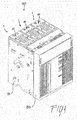
Figure 1 is a perspective view of a low voltage switch comprising a low voltage switch pole according to the invention; -
Figure 2 is a perspective view showing the poles arrangement of the low voltage switch ofFigure 1 ; -
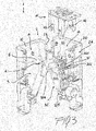
Figure 3 is an exploded view of an embodiment of a low voltage switch pole according to the invention; -
Figure 4 is a perspective view of the low voltage switch pole offigure 3 at the initial movement of the movable contact assembly from the closed position; -
Figure 5 is a perspective view of the low voltage switch pole offigure 3 in a first intermediate position of the movable contact assembly; -
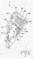
Figure 6 is a perspective view of the low voltage switch pole offigure 3 in a second intermediate position of the movable contact assembly; -
Figure 7 is a perspective view of the low voltage switch pole offigure 3 in the open position of the movable contact assembly; -
Figure 8 is a plan view of the low voltage switch pole offigure 3 at the initial movement of the movable contact assembly from the closed position; -
Figure 9 is a plan view of the low voltage switch pole offigure 3 in a first intermediate position of the movable contact assembly; -
Figure 10 is a plan view of the low voltage switch pole offigure 3 in a second intermediate position of the movable contact assembly; -
Figure 11 is a plan view of the low voltage switch pole offigure 3 in the open position of the movable contact assembly. - With reference to the attached figures, in particular to
figure 3 , a low voltage switch pole according to the invention, generally designated with the reference numeral 1, comprises in its more general definition aninsulating casing 2 having a first 21 and a second 22 lateral wall, afront wall 23 and arear wall 24. As represented in the attached figures, theinsulating casing 2 preferably comprises afirst half shell 10 and asecond half shell 20 that are coupled to each other so as to form theinsulating casing 2. In practice, thefirst half shell 10 comprises the first lateral wall 21, at least a portion of thefront wall 23 and at least a portion of therear wall 24, while thesecond half shell 20 comprises the secondlateral wall 22, at least a portion of thefront wall 23 and at least a portion of therear wall 24. - The internal space defined by the insulating
casing 2 comprises acontact area 3 and anarc extinguishing area 4 which is positioned at un upper level with respect to saidcontact area 3. - A fixed
contact assembly 31, comprisingelectrical contacts contact area 3 in correspondence of therear wall 24 of the insulatingcasing 2. Likewise, amovable contact assembly 32 is also positioned in saidcontact area 3, saidmovable contact assembly 32 being movable between a closed position in which it is into contact with the fixedcontact assembly 31 and an open position in which it is spaced apart from said fixedcontact assembly 31. - In the embodiment shown in the figures, the
movable contact assembly 32 generally compriseselectrical contacts structure 323 for supporting thecontacts axis 325 so as to allow engagement/disengagement of thecontacts contacts contact assembly 31. The supportingstructure 323 also comprises a connectingelement 324 which protrudes outside the insulatingcasing 2 from a window in thefront wall 23 for connection with a driving mechanism (not shown) operating the opening/closing of themovable contact assembly 32. Different structures of themovable contact assembly 32 are however possible. - The low voltage switch pole 1 according to the invention also comprises an
arc chamber 41 which in turn comprises a plurality of substantially parallelmetallic plates 42 inserted into anenclosure 43 made of insulating material. Saidarc chamber 41 is inserted into saidarc extinguishing area 4 so as to be positioned above saidcontact area 3. - One of the characterizing features of the low voltage switch pole 1 according to the invention is that an insulating
wall 5 is positioned in said internal space between saidcontact area 3 and saidarc extinguishing area 4 and partially separates saidcontact area 3 from saidarc extinguishing area 4. In this way, thecontact area 3 and thearc extinguishing area 4 are in direct communication with each other in the region near the fixed contact assembly 31 (i.e. near therear wall 24 of the insulating casing 2), thereby allowing arc formation in thearc chamber 41. Conversely, in the region near thefront wall 23 of the insulating casing 2 (i.e. opposite to the fixed contact assembly 31), thecontact area 3 and thearc extinguishing area 4 are isolated from each other by the insulatingwall 5, thereby avoiding a "jump" of the arc directly on the terminal plates of thearc chamber 41, bypassing some of the intermediatemetallic plates 42. - In practice, as shown in the attached figures, the insulating
wall 5 can be conveniently positioned in said internal space opposite to said fixedcontact assembly 31, i.e. in correspondence of thefront wall 23 of the insulatingcasing 2. - A further characterizing features of the low voltage switch pole 1 according to the invention is that a
channel 6 is provided in the insulatingwall 5. Thechannel 6 put thecontact area 3 into communication with thearc extinguishing area 4, allowing a passage of the hot gas developed during arc formation from thecontact area 3 to thearc extinguishing area 4. - As previously explained, the hot gas flows into the terminal portion of the
arc chamber 41 and greatly improves the fluid dynamics inside thearc chamber 41, helping (urging) the arc to develop throughout thewhole arc chamber 41 and involving allmetal plates 42. In particular, thechannel 6 connects a middle portion of saidcontact area 3 with a terminal portion of saidarc extinguishing area 4, i.e. the hot gases start passing through thechannel 6 from thecontact area 3 to thearc extinguishing area 4 when themovable contact assembly 32 is in an intermediate position between the closed position and the open position. - In practice, with reference to
figure 4 and8 , when themovable contacts assembly 32 starts separating from the fixedcontact assembly 31, an electrical arc (schematically illustrated as solid arrows between plates) is formed in the initial portion of thearc chamber 41 involving the first metallic plates 42 (i.e. those on the right hand side which are closer to the fixed contact assembly 31). - Then, while the
movable contacts assembly 32 is travelling in the intermediate positions offigures 5 ,9 and6 ,10 , the arc (schematically illustrated as solid arrows between plates) continues developing also in the middle portion of thearc chamber 41 involving also themetal plates 42 present in said middle portion; at the same time, the hot gases (schematically illustrated as dotted arrows) flow due to pressure build up from thecontact area 3 into thechannel 6 and then into the terminal portion of thearc chamber 41. - Finally, when the
movable contacts 32 is substantially in the open position offigures 7 ,11 , the arc has developed throughout thewhole arc chamber 41 involving substantially allmetallic plates 42. As clearly shown in this latter figures, the insulatingwall 5 is conveniently positioned in the internal space of the insulatingcasing 2 in correspondence of the open position of saidmovable contact assembly 32, thereby guaranteeing a perfect electrical insulation and avoiding any risk of arc striking / current leakage toward the external. - From a construction standpoint, in the low voltage switch pole 1 according to the present invention the insulating
wall 5 is preferably made integral with thefront wall 23 and thelateral walls 21 and 22 of thehalf shells casing 2. The insulatingwall 5 extends in the internal space of the insulatingcasing 2 from saidfront wall 23 in the direction of the fixedcontact assembly 31 and of therear wall 24, so as to partially separate thecontact area 3 from thearc extinguishing area 4. - In practice, in the embodiment illustrated in the figures, the insulating
wall 5 has aterminal edge 51 in correspondence of a middle portion of saidcontact area 3. Thechannel 6 has therefore afirst opening 61 which communicates with saidcontact area 3 proximate to saidterminal edge 51 and asecond opening 62 which communicates with saidarc extinguishing area 4 proximate to thefront wall 23 of the insulatingcasing 2. As previously said, in this way it is possible to convey the hot gases from the middle portion of thecontact area 3 to the terminal portion of thearc chamber 41. - The
metallic plates 42 of thearc chamber 41 can have different dimensions and shapes according to the needs. Themetallic plates 42 are generally inserted into theenclosure 43 of saidarc chamber 41 so that in the operating position a certain gap is left between their lower edge and saidcontact area 3, as well as between their lower edge and said movable 32 and fixed 31 contact assemblies. - In a largely preferred embodiment of the low voltage switch pole 1 according to the present invention, said
arc chamber 41 comprises a terminalmetallic plate 45 acting as a "roof" for saidarc chamber 41, i.e. acting so as to close thearc chamber 41 in the terminal portion thereof. - In practice, the terminal
metallic plate 45 is inserted into the insulatingenclosure 43 of saidarc chamber 41 at a lower level with respect to the othermetallic plates 42, so as to be located, when in the operating position, substantially in contact with, or very close to, the insulatingwall 5. - In such a case, the
channel 6 has afirst opening 61 which communicates with saidcontact area 3 in correspondence of a middle portion thereof and asecond opening 62 which communicates with saidarc extinguishing area 3 at a point between said terminalmetallic plate 45 and saidfront wall 23. In other words, according to this largely preferred embodiment the hot gases are vented from thecontact area 3 to a position in thearc chamber 41 which is beyond the "roof" formed by the terminalmetallic plate 45. - As is clear from the above description, the technical solutions adopted for the low voltage switch pole according to the present invention allow the proposed aims and the objects to be fully achieved.
- In particular, substantially all
metal plates 42 are involved during the arc quenching thereby allowing a more uniform utilization of thearc chamber 41. Less mechanical and thermal stresses are therefore generated into thearc chamber 41 with a consequent prolonged lifetime of it and of the associated switch pole. - Thanks to the insulating
wall 5, the possibility for the arc to bypass some of theintermediate metal plates 42 is substantially avoided and is also avoided or considerably reduced any risk of arc strikes toward the external of the pole 1. At the same time, thanks to thechannel 6 provided in the insulatingwall 5, the fluid dynamics of the hot gases is greatly improved, contributing to stripping the arc throughout thearc chamber 41 so as to involve allmetal plates 42. The improved flow of hot gases from thecontact area 3 to thearc extinguishing area 4 also helps cooling the movable contacts. - A
low voltage switch 100 comprising at least one low voltage switch pole 1 as previously described is also part of the present invention. - With reference to
figures 1 and2 , a three pole lowvoltage circuit breaker 100 comprising three low voltage switch poles 1 (i.e. circuit breaker poles) is shown. In this embodiment, the insulatingcasing 2 of each pole 1 is made of twohalf shells rigid flanks cover 103. From windows in thefront side 23 of the insulatingcasings 2, connectingelements 324 protrude outside for connection with a driving mechanism (not shown). The general structure of such low voltage circuit breaker is well known in the art and therefore will be not described in more details. - Several variations can be made to the low voltage switch pole thus conceived, all falling within the scope of the attached claims. In practice, the materials used and the contingent dimensions and shapes can be any, according to requirements and to the state of the art.
Claims (11)
- A low voltage switch pole (1) comprising an insulating casing (2) having lateral walls (21, 22) and a front (23) and a rear (24) wall and defining an internal space with a contact area (3) and an arc extinguishing area (4), a fixed contact assembly (31) and a movable contact assembly (32) being positioned in said contact area (3), said movable contact assembly (32) being movable between a closed position in which it is into contact with said fixed contact assembly (31) and an open position in which it is spaced apart from said fixed contact assembly (31), an arc chamber (41) comprising a plurality of substantially parallel metallic plates (42) inserted into an enclosure (43) made of insulating material being positioned in said arc extinguishing area (4), characterized in that an insulating wall (5) is positioned in said internal space between said contact area (3) and said arc extinguishing area (4) and partially separates said contact area (3) from said arc extinguishing area (4), and in that a channel (6) connecting said contact area (3) to said arc extinguishing area (4) is provided in said insulating wall (5).
- The low voltage switch pole (1) according to claim 1, characterized in that in said insulating casing (2) comprises a first half shell (10) and a second half shell (20).
- The low voltage switch pole (1) according to claim 1 or 2, characterized in that said channel (6) connects a middle portion of said contact area (3) with a terminal portion of said arc extinguishing area (4).
- The low voltage switch pole (1) according to one or more of the previous claims, characterized in that said insulating wall (5) is positioned in said internal space opposite to said fixed contact assembly (31).
- The low voltage switch pole (1) according to one or more of the previous claims, characterized in that said insulating wall (5) is positioned in said internal space in correspondence of the open position of said movable contact assembly (32).
- The low voltage switch pole (1) according to one or more of the previous claims, characterized in that said insulating wall (5) is integral with said front wall (23) and said lateral walls (21, 22) of said insulating casing (2) and extends in said internal space from said front wall (23) towards said fixed contact assembly (31) and said rear wall (24).
- The low voltage switch pole (1) according to claim 6, characterized in that said insulating wall (5) has a terminal edge (51) in correspondence of a middle portion of said contact area (3) and in that said channel (6) has a first opening (61) communicating with said contact area (3) proximate to said terminal edge (51) and a second opening (62) communicating with said arc extinguishing area (4) proximate to said front wall (23).
- The low voltage switch pole (1) according to one or more of the previous claims, characterized in that said metallic plates (42) are inserted into said enclosure (43) of said arc chamber (41) at a distance form said contact area (3) and said movable (32) and fixed (31) contact assemblies.
- The low voltage switch pole (1) according to one or more of the previous claims, characterized in that said arc chamber (41) comprises a terminal metallic plate (45) positioned at said insulating wall (5).
- The low voltage switch pole (1) according to claim 9, characterized in that said channel (6) opens into said arc extinguishing area (3) between said terminal metallic plate (45) and said front wall (23).
- A low voltage switch (100) characterized in that it comprises a low voltage switch pole (1) according to one or more of the previous claims.
Priority Applications (6)
| Application Number | Priority Date | Filing Date | Title |
|---|---|---|---|
| EP15152348.7A EP3048625B1 (en) | 2015-01-23 | 2015-01-23 | Low voltage switch pole |
| ES15152348.7T ES2645855T3 (en) | 2015-01-23 | 2015-01-23 | Low voltage switch pole |
| RU2016101154A RU2694433C2 (en) | 2015-01-23 | 2016-01-18 | Low-voltage switch pole and low-voltage switch with such pole |
| US15/003,131 US9715979B2 (en) | 2015-01-23 | 2016-01-21 | Low voltage switch pole |
| BR102016001454-9A BR102016001454B1 (en) | 2015-01-23 | 2016-01-22 | Low voltage switch pole and low voltage switch |
| CN201610041762.5A CN105826099B (en) | 2015-01-23 | 2016-01-22 | Low voltage switch pole |
Applications Claiming Priority (1)
| Application Number | Priority Date | Filing Date | Title |
|---|---|---|---|
| EP15152348.7A EP3048625B1 (en) | 2015-01-23 | 2015-01-23 | Low voltage switch pole |
Publications (2)
| Publication Number | Publication Date |
|---|---|
| EP3048625A1 true EP3048625A1 (en) | 2016-07-27 |
| EP3048625B1 EP3048625B1 (en) | 2017-08-16 |
Family
ID=52358715
Family Applications (1)
| Application Number | Title | Priority Date | Filing Date |
|---|---|---|---|
| EP15152348.7A Active EP3048625B1 (en) | 2015-01-23 | 2015-01-23 | Low voltage switch pole |
Country Status (6)
| Country | Link |
|---|---|
| US (1) | US9715979B2 (en) |
| EP (1) | EP3048625B1 (en) |
| CN (1) | CN105826099B (en) |
| BR (1) | BR102016001454B1 (en) |
| ES (1) | ES2645855T3 (en) |
| RU (1) | RU2694433C2 (en) |
Cited By (4)
| Publication number | Priority date | Publication date | Assignee | Title |
|---|---|---|---|---|
| CN108987209A (en) * | 2018-09-25 | 2018-12-11 | 西安柏泰电气有限公司 | A kind of arc-extinguish chamber |
| CN114695011A (en) * | 2020-12-30 | 2022-07-01 | 上海量乘机电科技有限公司 | Contact arc extinguishing system of electric switch |
| EP4177920A1 (en) * | 2021-11-08 | 2023-05-10 | ABB S.p.A. | Low voltage switch pole |
| EP4439603A1 (en) * | 2023-03-27 | 2024-10-02 | ABB S.p.A. | Low voltage switch pole with a baffle arrangement |
Families Citing this family (14)
| Publication number | Priority date | Publication date | Assignee | Title |
|---|---|---|---|---|
| USD587658S1 (en) * | 2005-05-10 | 2009-03-03 | Abb S.P.A. | Circuit breaker |
| BR302013002178S1 (en) * | 2012-11-09 | 2014-11-25 | Abb Spa | FUSE APPLICATION |
| KR20180114763A (en) * | 2017-04-11 | 2018-10-19 | 엘에스산전 주식회사 | Arc gas venting structure of air circuit breaker |
| FR3066642B1 (en) * | 2017-05-17 | 2020-09-04 | Schneider Electric Ind Sas | REMOVABLE ELEMENT FOR CUTTING AN ELECTRIC CURRENT AND ELECTRICAL CUTTING DEVICE FOR AN ELECTRIC CURRENT INCLUDING SUCH A REMOVABLE CUTTING ELEMENT |
| USD858458S1 (en) * | 2017-08-22 | 2019-09-03 | Siemens Aktiengesellschaft | Switching device |
| USD959388S1 (en) * | 2020-01-15 | 2022-08-02 | Siemens Aktiengesellschaft | Switching device |
| KR102349756B1 (en) * | 2020-03-03 | 2022-01-11 | 엘에스일렉트릭(주) | Arc extinguishing assembly and circuit breaker having thereof |
| CN114496643B (en) * | 2020-10-25 | 2024-10-22 | Abb瑞士股份有限公司 | Interrupter for direct current interruption |
| KR102666105B1 (en) * | 2021-05-11 | 2024-05-16 | 엘에스일렉트릭(주) | Circuit breaker part and air circuit breaker include the same |
| US12620536B2 (en) * | 2021-05-14 | 2026-05-05 | Ls Electric Co., Ltd. | Circuit breaking unit and air circuit breaker including same |
| KR102666107B1 (en) * | 2021-05-14 | 2024-05-16 | 엘에스일렉트릭(주) | Arc extinguish part and air circuit breaker include the same |
| EP4177921A1 (en) * | 2021-11-08 | 2023-05-10 | ABB S.p.A. | Low voltage switch pole |
| EP4336531B1 (en) | 2022-09-06 | 2026-04-08 | ABB S.p.A. | Low voltage switch pole with an arc breaking element having a cover for hot gases with a plate element and a through hole |
| EP4415014A1 (en) * | 2023-02-07 | 2024-08-14 | ABB S.p.A. | Low-voltage switch pole |
Citations (4)
| Publication number | Priority date | Publication date | Assignee | Title |
|---|---|---|---|---|
| US4958135A (en) * | 1987-12-10 | 1990-09-18 | Merlin Gerin | High rating molded case multipole circuit breaker |
| US5899323A (en) * | 1998-05-07 | 1999-05-04 | Eaton Corporation | Electrical switching apparatus with contact finger guide |
| US6248971B1 (en) * | 1998-05-12 | 2001-06-19 | Schneider Electric Sa | Circuit breaker with parallel connected pole compartments |
| US20050151605A1 (en) * | 2002-04-26 | 2005-07-14 | Michael Kruschke | Electric power circuit breaker comprising a connecting bar and an arcing horn |
Family Cites Families (22)
| Publication number | Priority date | Publication date | Assignee | Title |
|---|---|---|---|---|
| US3632926A (en) * | 1970-04-20 | 1972-01-04 | Gen Electric | Current-limiting circuit breaker having arc extinguishing means which includes improved arc initiation and extinguishing chamber construction |
| US4082931A (en) * | 1976-04-12 | 1978-04-04 | Westinghouse Electric Corporation | Arc chute |
| US4088973A (en) * | 1976-04-28 | 1978-05-09 | Gould Inc. | Unitized combination starter |
| US4218596A (en) * | 1978-01-16 | 1980-08-19 | Gould Inc. | Circuit breaker molded housing |
| US4612426A (en) * | 1985-08-23 | 1986-09-16 | Westinghouse Electric Corp. | Arc chute assembly for circuit breaker |
| RU2136074C1 (en) * | 1996-09-30 | 1999-08-27 | Акционерное общество закрытого типа "Контактор" | Automatic switch |
| US6222147B1 (en) * | 2000-03-09 | 2001-04-24 | General Electric Company | Circuit breaker arc exhaust baffle with variable aperture |
| US6281459B1 (en) * | 2000-04-21 | 2001-08-28 | Eaton Corporation | Circuit interrupter having an improved slot motor assembly |
| US6417474B1 (en) * | 2001-05-15 | 2002-07-09 | Eaton Corporation | Electrical switching apparatus having an arc runner with an elongated raised ridge |
| US6703576B1 (en) * | 2003-02-13 | 2004-03-09 | Eaton Corporation | Arc chute with valve and electric power switch incorporating same |
| US7009132B1 (en) * | 2004-09-03 | 2006-03-07 | Eaton Corporation | Terminal assembly for vented circuit breaker and circuit breaker incorporating same |
| US7488915B2 (en) * | 2006-09-20 | 2009-02-10 | Eaton Corporation | ARC baffle, and ARC chute assembly and electrical switching apparatus employing the same |
| US7674996B2 (en) * | 2006-09-20 | 2010-03-09 | Eaton Corporation | Gassing insulator, and arc chute assembly and electrical switching apparatus employing the same |
| DE102008005101A1 (en) * | 2008-01-16 | 2009-07-23 | Siemens Aktiengesellschaft | Switching device, in particular power switching device |
| WO2011097612A1 (en) * | 2010-02-08 | 2011-08-11 | Siemens Aktiengesellschaft | Circuit breaker electrical contact assembly, and systems and methods using same |
| US8138439B2 (en) * | 2010-02-11 | 2012-03-20 | Eaton Corporation | Limiter including a number of gas channels and electrical switching apparatus employing the same |
| US8222555B2 (en) * | 2010-08-17 | 2012-07-17 | Eaton Corporation | Circuit breaker and arc chute with shield apparatus |
| RU2450405C1 (en) * | 2011-04-18 | 2012-05-10 | Открытое акционерное общество "Научно-производственное предприятие "Рубин" (ОАО "НПП "Рубин") | Rectifying voltage stabiliser |
| US9040864B2 (en) * | 2013-05-27 | 2015-05-26 | Asco Power Technologies, L.P. | Profiled arc splitter plate |
| KR101513208B1 (en) * | 2013-11-08 | 2015-04-17 | 엘에스산전 주식회사 | Molded case circuit breaker |
| KR101513209B1 (en) * | 2013-11-08 | 2015-04-17 | 엘에스산전 주식회사 | Molded case circuit breaker |
| US9852851B2 (en) * | 2014-10-21 | 2017-12-26 | General Electric Company | Molded case circuit breaker with current sensing unit |
-
2015
- 2015-01-23 ES ES15152348.7T patent/ES2645855T3/en active Active
- 2015-01-23 EP EP15152348.7A patent/EP3048625B1/en active Active
-
2016
- 2016-01-18 RU RU2016101154A patent/RU2694433C2/en active
- 2016-01-21 US US15/003,131 patent/US9715979B2/en active Active
- 2016-01-22 CN CN201610041762.5A patent/CN105826099B/en active Active
- 2016-01-22 BR BR102016001454-9A patent/BR102016001454B1/en active IP Right Grant
Patent Citations (4)
| Publication number | Priority date | Publication date | Assignee | Title |
|---|---|---|---|---|
| US4958135A (en) * | 1987-12-10 | 1990-09-18 | Merlin Gerin | High rating molded case multipole circuit breaker |
| US5899323A (en) * | 1998-05-07 | 1999-05-04 | Eaton Corporation | Electrical switching apparatus with contact finger guide |
| US6248971B1 (en) * | 1998-05-12 | 2001-06-19 | Schneider Electric Sa | Circuit breaker with parallel connected pole compartments |
| US20050151605A1 (en) * | 2002-04-26 | 2005-07-14 | Michael Kruschke | Electric power circuit breaker comprising a connecting bar and an arcing horn |
Cited By (6)
| Publication number | Priority date | Publication date | Assignee | Title |
|---|---|---|---|---|
| CN108987209A (en) * | 2018-09-25 | 2018-12-11 | 西安柏泰电气有限公司 | A kind of arc-extinguish chamber |
| CN108987209B (en) * | 2018-09-25 | 2024-03-08 | 西安柏泰电气有限公司 | Arc extinguishing cover |
| CN114695011A (en) * | 2020-12-30 | 2022-07-01 | 上海量乘机电科技有限公司 | Contact arc extinguishing system of electric switch |
| EP4177920A1 (en) * | 2021-11-08 | 2023-05-10 | ABB S.p.A. | Low voltage switch pole |
| US12087525B2 (en) | 2021-11-08 | 2024-09-10 | Abb S.P.A. | Low voltage switch pole |
| EP4439603A1 (en) * | 2023-03-27 | 2024-10-02 | ABB S.p.A. | Low voltage switch pole with a baffle arrangement |
Also Published As
| Publication number | Publication date |
|---|---|
| RU2694433C2 (en) | 2019-07-15 |
| US20160217950A1 (en) | 2016-07-28 |
| BR102016001454A2 (en) | 2016-09-13 |
| BR102016001454B1 (en) | 2022-04-19 |
| US9715979B2 (en) | 2017-07-25 |
| RU2016101154A (en) | 2017-07-19 |
| CN105826099B (en) | 2019-05-17 |
| EP3048625B1 (en) | 2017-08-16 |
| RU2016101154A3 (en) | 2019-05-21 |
| CN105826099A (en) | 2016-08-03 |
| ES2645855T3 (en) | 2017-12-11 |
Similar Documents
| Publication | Publication Date | Title |
|---|---|---|
| EP3048625B1 (en) | Low voltage switch pole | |
| CN213184182U (en) | Switch electric appliance | |
| US10665403B2 (en) | Low-voltage multipolar circuit breaker | |
| US11837427B2 (en) | Arc chamber for a low-voltage switching device | |
| US11404225B2 (en) | Low-voltage circuit breaker | |
| US12237131B2 (en) | Device for door and phase segregation in molded case circuit breakers | |
| US11302502B2 (en) | Terminal clamp cover device for low voltage circuit breakers | |
| US11355290B2 (en) | Low voltage switch pole | |
| KR20210007390A (en) | Arc Extinguishing Unit of Molded Case Circuit Breaker | |
| KR200463716Y1 (en) | Cold current construction of air circuit breaker | |
| EP4489047A1 (en) | Air circuit breaker | |
| KR20150089729A (en) | Arc Extinguishing Device of Molded Case Circuit Breaker | |
| KR100442298B1 (en) | the device for terminal cover in circuit breaker | |
| CN223785021U (en) | Switching devices and power systems | |
| EP4177920B1 (en) | Low voltage switch pole | |
| US12362113B2 (en) | Low voltage switch pole | |
| CN219203078U (en) | Zero arcing cover for molded case circuit breaker | |
| EP4439603A1 (en) | Low voltage switch pole with a baffle arrangement | |
| GB2587467A (en) | Terminal clamp cover device for low voltage circuit breakers | |
| KR20190002093U (en) | Distinguishing Unit of Molded Case Circuit Breaker | |
| CN110098095A (en) | Air-sweeping type low-voltage arc eliminating device and breaker |
Legal Events
| Date | Code | Title | Description |
|---|---|---|---|
| PUAI | Public reference made under article 153(3) epc to a published international application that has entered the european phase |
Free format text: ORIGINAL CODE: 0009012 |
|
| AK | Designated contracting states |
Kind code of ref document: A1 Designated state(s): AL AT BE BG CH CY CZ DE DK EE ES FI FR GB GR HR HU IE IS IT LI LT LU LV MC MK MT NL NO PL PT RO RS SE SI SK SM TR |
|
| AX | Request for extension of the european patent |
Extension state: BA ME |
|
| 17P | Request for examination filed |
Effective date: 20170117 |
|
| RBV | Designated contracting states (corrected) |
Designated state(s): AL AT BE BG CH CY CZ DE DK EE ES FI FR GB GR HR HU IE IS IT LI LT LU LV MC MK MT NL NO PL PT RO RS SE SI SK SM TR |
|
| GRAJ | Information related to disapproval of communication of intention to grant by the applicant or resumption of examination proceedings by the epo deleted |
Free format text: ORIGINAL CODE: EPIDOSDIGR1 |
|
| GRAP | Despatch of communication of intention to grant a patent |
Free format text: ORIGINAL CODE: EPIDOSNIGR1 |
|
| RIC1 | Information provided on ipc code assigned before grant |
Ipc: H01H 9/34 20060101AFI20170217BHEP |
|
| INTG | Intention to grant announced |
Effective date: 20170313 |
|
| GRAS | Grant fee paid |
Free format text: ORIGINAL CODE: EPIDOSNIGR3 |
|
| GRAA | (expected) grant |
Free format text: ORIGINAL CODE: 0009210 |
|
| AK | Designated contracting states |
Kind code of ref document: B1 Designated state(s): AL AT BE BG CH CY CZ DE DK EE ES FI FR GB GR HR HU IE IS IT LI LT LU LV MC MK MT NL NO PL PT RO RS SE SI SK SM TR |
|
| REG | Reference to a national code |
Ref country code: GB Ref legal event code: FG4D |
|
| REG | Reference to a national code |
Ref country code: CH Ref legal event code: EP |
|
| REG | Reference to a national code |
Ref country code: IE Ref legal event code: FG4D |
|
| REG | Reference to a national code |
Ref country code: AT Ref legal event code: REF Ref document number: 919824 Country of ref document: AT Kind code of ref document: T Effective date: 20170915 |
|
| REG | Reference to a national code |
Ref country code: DE Ref legal event code: R096 Ref document number: 602015004072 Country of ref document: DE |
|
| REG | Reference to a national code |
Ref country code: SE Ref legal event code: TRGR |
|
| REG | Reference to a national code |
Ref country code: ES Ref legal event code: FG2A Ref document number: 2645855 Country of ref document: ES Kind code of ref document: T3 Effective date: 20171211 |
|
| REG | Reference to a national code |
Ref country code: NL Ref legal event code: MP Effective date: 20170816 |
|
| REG | Reference to a national code |
Ref country code: LT Ref legal event code: MG4D |
|
| REG | Reference to a national code |
Ref country code: AT Ref legal event code: MK05 Ref document number: 919824 Country of ref document: AT Kind code of ref document: T Effective date: 20170816 |
|
| REG | Reference to a national code |
Ref country code: FR Ref legal event code: PLFP Year of fee payment: 4 |
|
| PG25 | Lapsed in a contracting state [announced via postgrant information from national office to epo] |
Ref country code: NL Free format text: LAPSE BECAUSE OF FAILURE TO SUBMIT A TRANSLATION OF THE DESCRIPTION OR TO PAY THE FEE WITHIN THE PRESCRIBED TIME-LIMIT Effective date: 20170816 Ref country code: AT Free format text: LAPSE BECAUSE OF FAILURE TO SUBMIT A TRANSLATION OF THE DESCRIPTION OR TO PAY THE FEE WITHIN THE PRESCRIBED TIME-LIMIT Effective date: 20170816 Ref country code: LT Free format text: LAPSE BECAUSE OF FAILURE TO SUBMIT A TRANSLATION OF THE DESCRIPTION OR TO PAY THE FEE WITHIN THE PRESCRIBED TIME-LIMIT Effective date: 20170816 Ref country code: NO Free format text: LAPSE BECAUSE OF FAILURE TO SUBMIT A TRANSLATION OF THE DESCRIPTION OR TO PAY THE FEE WITHIN THE PRESCRIBED TIME-LIMIT Effective date: 20171116 Ref country code: FI Free format text: LAPSE BECAUSE OF FAILURE TO SUBMIT A TRANSLATION OF THE DESCRIPTION OR TO PAY THE FEE WITHIN THE PRESCRIBED TIME-LIMIT Effective date: 20170816 |
|
| PG25 | Lapsed in a contracting state [announced via postgrant information from national office to epo] |
Ref country code: IS Free format text: LAPSE BECAUSE OF FAILURE TO SUBMIT A TRANSLATION OF THE DESCRIPTION OR TO PAY THE FEE WITHIN THE PRESCRIBED TIME-LIMIT Effective date: 20171216 Ref country code: RS Free format text: LAPSE BECAUSE OF FAILURE TO SUBMIT A TRANSLATION OF THE DESCRIPTION OR TO PAY THE FEE WITHIN THE PRESCRIBED TIME-LIMIT Effective date: 20170816 Ref country code: LV Free format text: LAPSE BECAUSE OF FAILURE TO SUBMIT A TRANSLATION OF THE DESCRIPTION OR TO PAY THE FEE WITHIN THE PRESCRIBED TIME-LIMIT Effective date: 20170816 Ref country code: BG Free format text: LAPSE BECAUSE OF FAILURE TO SUBMIT A TRANSLATION OF THE DESCRIPTION OR TO PAY THE FEE WITHIN THE PRESCRIBED TIME-LIMIT Effective date: 20171116 Ref country code: PL Free format text: LAPSE BECAUSE OF FAILURE TO SUBMIT A TRANSLATION OF THE DESCRIPTION OR TO PAY THE FEE WITHIN THE PRESCRIBED TIME-LIMIT Effective date: 20170816 |
|
| PG25 | Lapsed in a contracting state [announced via postgrant information from national office to epo] |
Ref country code: RO Free format text: LAPSE BECAUSE OF FAILURE TO SUBMIT A TRANSLATION OF THE DESCRIPTION OR TO PAY THE FEE WITHIN THE PRESCRIBED TIME-LIMIT Effective date: 20170816 Ref country code: CZ Free format text: LAPSE BECAUSE OF FAILURE TO SUBMIT A TRANSLATION OF THE DESCRIPTION OR TO PAY THE FEE WITHIN THE PRESCRIBED TIME-LIMIT Effective date: 20170816 Ref country code: DK Free format text: LAPSE BECAUSE OF FAILURE TO SUBMIT A TRANSLATION OF THE DESCRIPTION OR TO PAY THE FEE WITHIN THE PRESCRIBED TIME-LIMIT Effective date: 20170816 |
|
| REG | Reference to a national code |
Ref country code: GR Ref legal event code: EP Ref document number: 20170403095 Country of ref document: GR Effective date: 20180420 |
|
| REG | Reference to a national code |
Ref country code: DE Ref legal event code: R097 Ref document number: 602015004072 Country of ref document: DE |
|
| PG25 | Lapsed in a contracting state [announced via postgrant information from national office to epo] |
Ref country code: SM Free format text: LAPSE BECAUSE OF FAILURE TO SUBMIT A TRANSLATION OF THE DESCRIPTION OR TO PAY THE FEE WITHIN THE PRESCRIBED TIME-LIMIT Effective date: 20170816 Ref country code: SK Free format text: LAPSE BECAUSE OF FAILURE TO SUBMIT A TRANSLATION OF THE DESCRIPTION OR TO PAY THE FEE WITHIN THE PRESCRIBED TIME-LIMIT Effective date: 20170816 Ref country code: EE Free format text: LAPSE BECAUSE OF FAILURE TO SUBMIT A TRANSLATION OF THE DESCRIPTION OR TO PAY THE FEE WITHIN THE PRESCRIBED TIME-LIMIT Effective date: 20170816 |
|
| PLBE | No opposition filed within time limit |
Free format text: ORIGINAL CODE: 0009261 |
|
| STAA | Information on the status of an ep patent application or granted ep patent |
Free format text: STATUS: NO OPPOSITION FILED WITHIN TIME LIMIT |
|
| 26N | No opposition filed |
Effective date: 20180517 |
|
| PG25 | Lapsed in a contracting state [announced via postgrant information from national office to epo] |
Ref country code: SI Free format text: LAPSE BECAUSE OF FAILURE TO SUBMIT A TRANSLATION OF THE DESCRIPTION OR TO PAY THE FEE WITHIN THE PRESCRIBED TIME-LIMIT Effective date: 20170816 |
|
| REG | Reference to a national code |
Ref country code: CH Ref legal event code: PL |
|
| PG25 | Lapsed in a contracting state [announced via postgrant information from national office to epo] |
Ref country code: LU Free format text: LAPSE BECAUSE OF NON-PAYMENT OF DUE FEES Effective date: 20180123 |
|
| REG | Reference to a national code |
Ref country code: IE Ref legal event code: MM4A |
|
| REG | Reference to a national code |
Ref country code: BE Ref legal event code: MM Effective date: 20180131 |
|
| PG25 | Lapsed in a contracting state [announced via postgrant information from national office to epo] |
Ref country code: LI Free format text: LAPSE BECAUSE OF NON-PAYMENT OF DUE FEES Effective date: 20180131 Ref country code: CH Free format text: LAPSE BECAUSE OF NON-PAYMENT OF DUE FEES Effective date: 20180131 Ref country code: BE Free format text: LAPSE BECAUSE OF NON-PAYMENT OF DUE FEES Effective date: 20180131 |
|
| PG25 | Lapsed in a contracting state [announced via postgrant information from national office to epo] |
Ref country code: IE Free format text: LAPSE BECAUSE OF NON-PAYMENT OF DUE FEES Effective date: 20180123 |
|
| PG25 | Lapsed in a contracting state [announced via postgrant information from national office to epo] |
Ref country code: MC Free format text: LAPSE BECAUSE OF FAILURE TO SUBMIT A TRANSLATION OF THE DESCRIPTION OR TO PAY THE FEE WITHIN THE PRESCRIBED TIME-LIMIT Effective date: 20170816 |
|
| PG25 | Lapsed in a contracting state [announced via postgrant information from national office to epo] |
Ref country code: MT Free format text: LAPSE BECAUSE OF NON-PAYMENT OF DUE FEES Effective date: 20180123 |
|
| PG25 | Lapsed in a contracting state [announced via postgrant information from national office to epo] |
Ref country code: TR Free format text: LAPSE BECAUSE OF FAILURE TO SUBMIT A TRANSLATION OF THE DESCRIPTION OR TO PAY THE FEE WITHIN THE PRESCRIBED TIME-LIMIT Effective date: 20170816 |
|
| PG25 | Lapsed in a contracting state [announced via postgrant information from national office to epo] |
Ref country code: PT Free format text: LAPSE BECAUSE OF FAILURE TO SUBMIT A TRANSLATION OF THE DESCRIPTION OR TO PAY THE FEE WITHIN THE PRESCRIBED TIME-LIMIT Effective date: 20170816 |
|
| PG25 | Lapsed in a contracting state [announced via postgrant information from national office to epo] |
Ref country code: MK Free format text: LAPSE BECAUSE OF NON-PAYMENT OF DUE FEES Effective date: 20170816 Ref country code: HR Free format text: LAPSE BECAUSE OF FAILURE TO SUBMIT A TRANSLATION OF THE DESCRIPTION OR TO PAY THE FEE WITHIN THE PRESCRIBED TIME-LIMIT Effective date: 20170816 Ref country code: CY Free format text: LAPSE BECAUSE OF FAILURE TO SUBMIT A TRANSLATION OF THE DESCRIPTION OR TO PAY THE FEE WITHIN THE PRESCRIBED TIME-LIMIT Effective date: 20170816 Ref country code: HU Free format text: LAPSE BECAUSE OF FAILURE TO SUBMIT A TRANSLATION OF THE DESCRIPTION OR TO PAY THE FEE WITHIN THE PRESCRIBED TIME-LIMIT; INVALID AB INITIO Effective date: 20150123 |
|
| PG25 | Lapsed in a contracting state [announced via postgrant information from national office to epo] |
Ref country code: AL Free format text: LAPSE BECAUSE OF FAILURE TO SUBMIT A TRANSLATION OF THE DESCRIPTION OR TO PAY THE FEE WITHIN THE PRESCRIBED TIME-LIMIT Effective date: 20170816 |
|
| PGFP | Annual fee paid to national office [announced via postgrant information from national office to epo] |
Ref country code: SE Payment date: 20260121 Year of fee payment: 12 |
|
| PGFP | Annual fee paid to national office [announced via postgrant information from national office to epo] |
Ref country code: GB Payment date: 20260123 Year of fee payment: 12 |
|
| PGFP | Annual fee paid to national office [announced via postgrant information from national office to epo] |
Ref country code: ES Payment date: 20260227 Year of fee payment: 12 |
|
| PGFP | Annual fee paid to national office [announced via postgrant information from national office to epo] |
Ref country code: DE Payment date: 20260121 Year of fee payment: 12 |
|
| PGFP | Annual fee paid to national office [announced via postgrant information from national office to epo] |
Ref country code: IT Payment date: 20260126 Year of fee payment: 12 |
|
| PGFP | Annual fee paid to national office [announced via postgrant information from national office to epo] |
Ref country code: FR Payment date: 20260123 Year of fee payment: 12 |
|
| PGFP | Annual fee paid to national office [announced via postgrant information from national office to epo] |
Ref country code: GR Payment date: 20260122 Year of fee payment: 12 |