EP3048584A1 - Visualisation of the position of a mobile device - Google Patents
Visualisation of the position of a mobile device Download PDFInfo
- Publication number
- EP3048584A1 EP3048584A1 EP15160481.6A EP15160481A EP3048584A1 EP 3048584 A1 EP3048584 A1 EP 3048584A1 EP 15160481 A EP15160481 A EP 15160481A EP 3048584 A1 EP3048584 A1 EP 3048584A1
- Authority
- EP
- European Patent Office
- Prior art keywords
- mobile device
- remote observation
- parameters
- render
- vector data
- Prior art date
- Legal status (The legal status is an assumption and is not a legal conclusion. Google has not performed a legal analysis and makes no representation as to the accuracy of the status listed.)
- Granted
Links
- 238000012800 visualization Methods 0.000 title claims description 61
- 238000004891 communication Methods 0.000 claims abstract description 58
- 238000000034 method Methods 0.000 claims description 76
- 230000003044 adaptive effect Effects 0.000 claims description 62
- 230000008569 process Effects 0.000 claims description 61
- 238000007794 visualization technique Methods 0.000 claims description 12
- 230000002596 correlated effect Effects 0.000 claims description 8
- 230000008859 change Effects 0.000 abstract description 12
- 238000009877 rendering Methods 0.000 description 67
- 230000010363 phase shift Effects 0.000 description 21
- 230000007704 transition Effects 0.000 description 21
- 230000005540 biological transmission Effects 0.000 description 15
- 230000003247 decreasing effect Effects 0.000 description 14
- 230000026676 system process Effects 0.000 description 11
- 238000013459 approach Methods 0.000 description 10
- 230000001413 cellular effect Effects 0.000 description 8
- 230000001133 acceleration Effects 0.000 description 5
- 238000005457 optimization Methods 0.000 description 5
- 230000001788 irregular Effects 0.000 description 4
- 238000012544 monitoring process Methods 0.000 description 4
- 238000012545 processing Methods 0.000 description 4
- 230000000875 corresponding effect Effects 0.000 description 3
- 239000002826 coolant Substances 0.000 description 2
- 230000008878 coupling Effects 0.000 description 2
- 238000010168 coupling process Methods 0.000 description 2
- 238000005859 coupling reaction Methods 0.000 description 2
- 230000007423 decrease Effects 0.000 description 2
- 230000002950 deficient Effects 0.000 description 2
- 230000003111 delayed effect Effects 0.000 description 2
- 230000035484 reaction time Effects 0.000 description 2
- 230000004044 response Effects 0.000 description 2
- 238000004458 analytical method Methods 0.000 description 1
- 238000012937 correction Methods 0.000 description 1
- 230000001934 delay Effects 0.000 description 1
- 238000010586 diagram Methods 0.000 description 1
- 230000000694 effects Effects 0.000 description 1
- 238000005516 engineering process Methods 0.000 description 1
- 238000011156 evaluation Methods 0.000 description 1
- 238000013213 extrapolation Methods 0.000 description 1
- 239000000446 fuel Substances 0.000 description 1
- 238000010295 mobile communication Methods 0.000 description 1
- 238000012986 modification Methods 0.000 description 1
- 230000004048 modification Effects 0.000 description 1
- 230000000737 periodic effect Effects 0.000 description 1
- 230000002093 peripheral effect Effects 0.000 description 1
- 230000009467 reduction Effects 0.000 description 1
- 238000012552 review Methods 0.000 description 1
- 238000005070 sampling Methods 0.000 description 1
- 230000035939 shock Effects 0.000 description 1
- 230000001960 triggered effect Effects 0.000 description 1
Images


Classifications
-
- H—ELECTRICITY
- H04—ELECTRIC COMMUNICATION TECHNIQUE
- H04W—WIRELESS COMMUNICATION NETWORKS
- H04W4/00—Services specially adapted for wireless communication networks; Facilities therefor
- H04W4/02—Services making use of location information
- H04W4/029—Location-based management or tracking services
-
- G—PHYSICS
- G01—MEASURING; TESTING
- G01C—MEASURING DISTANCES, LEVELS OR BEARINGS; SURVEYING; NAVIGATION; GYROSCOPIC INSTRUMENTS; PHOTOGRAMMETRY OR VIDEOGRAMMETRY
- G01C21/00—Navigation; Navigational instruments not provided for in groups G01C1/00 - G01C19/00
- G01C21/26—Navigation; Navigational instruments not provided for in groups G01C1/00 - G01C19/00 specially adapted for navigation in a road network
- G01C21/34—Route searching; Route guidance
- G01C21/36—Input/output arrangements for on-board computers
- G01C21/3667—Display of a road map
-
- G—PHYSICS
- G06—COMPUTING; CALCULATING OR COUNTING
- G06T—IMAGE DATA PROCESSING OR GENERATION, IN GENERAL
- G06T1/00—General purpose image data processing
- G06T1/20—Processor architectures; Processor configuration, e.g. pipelining
-
- G—PHYSICS
- G06—COMPUTING; CALCULATING OR COUNTING
- G06T—IMAGE DATA PROCESSING OR GENERATION, IN GENERAL
- G06T11/00—2D [Two Dimensional] image generation
- G06T11/20—Drawing from basic elements, e.g. lines or circles
- G06T11/206—Drawing of charts or graphs
-
- G—PHYSICS
- G07—CHECKING-DEVICES
- G07B—TICKET-ISSUING APPARATUS; FARE-REGISTERING APPARATUS; FRANKING APPARATUS
- G07B15/00—Arrangements or apparatus for collecting fares, tolls or entrance fees at one or more control points
-
- G—PHYSICS
- G08—SIGNALLING
- G08G—TRAFFIC CONTROL SYSTEMS
- G08G1/00—Traffic control systems for road vehicles
- G08G1/01—Detecting movement of traffic to be counted or controlled
- G08G1/0104—Measuring and analyzing of parameters relative to traffic conditions
- G08G1/0108—Measuring and analyzing of parameters relative to traffic conditions based on the source of data
- G08G1/0112—Measuring and analyzing of parameters relative to traffic conditions based on the source of data from the vehicle, e.g. floating car data [FCD]
-
- G—PHYSICS
- G08—SIGNALLING
- G08G—TRAFFIC CONTROL SYSTEMS
- G08G1/00—Traffic control systems for road vehicles
- G08G1/01—Detecting movement of traffic to be counted or controlled
- G08G1/0104—Measuring and analyzing of parameters relative to traffic conditions
- G08G1/0125—Traffic data processing
- G08G1/0129—Traffic data processing for creating historical data or processing based on historical data
-
- G—PHYSICS
- G08—SIGNALLING
- G08G—TRAFFIC CONTROL SYSTEMS
- G08G1/00—Traffic control systems for road vehicles
- G08G1/01—Detecting movement of traffic to be counted or controlled
- G08G1/052—Detecting movement of traffic to be counted or controlled with provision for determining speed or overspeed
-
- G—PHYSICS
- G08—SIGNALLING
- G08G—TRAFFIC CONTROL SYSTEMS
- G08G1/00—Traffic control systems for road vehicles
- G08G1/20—Monitoring the location of vehicles belonging to a group, e.g. fleet of vehicles, countable or determined number of vehicles
-
- H—ELECTRICITY
- H04—ELECTRIC COMMUNICATION TECHNIQUE
- H04W—WIRELESS COMMUNICATION NETWORKS
- H04W4/00—Services specially adapted for wireless communication networks; Facilities therefor
- H04W4/02—Services making use of location information
- H04W4/025—Services making use of location information using location based information parameters
- H04W4/027—Services making use of location information using location based information parameters using movement velocity, acceleration information
-
- G—PHYSICS
- G06—COMPUTING; CALCULATING OR COUNTING
- G06T—IMAGE DATA PROCESSING OR GENERATION, IN GENERAL
- G06T2200/00—Indexing scheme for image data processing or generation, in general
- G06T2200/16—Indexing scheme for image data processing or generation, in general involving adaptation to the client's capabilities
-
- G—PHYSICS
- G06—COMPUTING; CALCULATING OR COUNTING
- G06T—IMAGE DATA PROCESSING OR GENERATION, IN GENERAL
- G06T2200/00—Indexing scheme for image data processing or generation, in general
- G06T2200/28—Indexing scheme for image data processing or generation, in general involving image processing hardware
-
- G—PHYSICS
- G07—CHECKING-DEVICES
- G07C—TIME OR ATTENDANCE REGISTERS; REGISTERING OR INDICATING THE WORKING OF MACHINES; GENERATING RANDOM NUMBERS; VOTING OR LOTTERY APPARATUS; ARRANGEMENTS, SYSTEMS OR APPARATUS FOR CHECKING NOT PROVIDED FOR ELSEWHERE
- G07C5/00—Registering or indicating the working of vehicles
- G07C5/008—Registering or indicating the working of vehicles communicating information to a remotely located station
Landscapes
- General Physics & Mathematics (AREA)
- Physics & Mathematics (AREA)
- Engineering & Computer Science (AREA)
- Remote Sensing (AREA)
- Radar, Positioning & Navigation (AREA)
- Chemical & Material Sciences (AREA)
- Analytical Chemistry (AREA)
- Computer Networks & Wireless Communication (AREA)
- Signal Processing (AREA)
- Theoretical Computer Science (AREA)
- Automation & Control Theory (AREA)
- Finance (AREA)
- Business, Economics & Management (AREA)
- Navigation (AREA)
Abstract
Description
- The present invention generally relates to a method and apparatus for a telemetry furtherance visualization system. More specifically, the present invention relates to visualizing the advancement of a mobile device as a rendered graphical representation on a digital display based upon a series of historical logs of mobile device vector data.
- Mobile Telemetry systems with mobile device rendering capabilities are known in the prior art. Mobile information may be sensed, logged as data and transmitted for subsequent data processing and rendering on a computing device. Data transmission and rendering on a digital map may be based upon different approaches to receiving a log of data. The log of data may be received randomly and unexpected in time, periodic or expected at a repeating point in time as well as aperiodic irregular points in time. The random and aperiodic approaches can result in rendering positional errors on a graphical map of a computing device.
- United States patent
US6845318 issued on January 18, 2005 to Moore et al. al. and relates to methods, data structures and systems that provide techniques for processing track logs. A track log is represented as a number of track points. The track points represent geographic positions previously travelled. The track log and the track points are overlaid on a map and presented on a display in communication with a portable navigation device. Track points are graphically selected and identified via the display. Any graphically selected track point is also associated with a selectable operation for immediate, automatic and/or subsequent execution on a portable navigation device. - United States patent application
US201/0047244 published on November 29, 2001 to Harrison and Morris . This patent application relates to a data monitoring apparatus including a GPS receiver, a micro controller, a number of sensors, a number of actuators, memory, a radio transmitter and a data communication antennae. The apparatus accumulates real time data concerning position and time and other operational parameters of a geographically mobile object such as a vehicle for transmission to a monitoring station. Transmission channel utility may be improved through transmission of accumulated historical data to a separate monitoring station. - United States patent application
US2012/0253862 published on October 4, 2012 to Davidson . This patent application relates a fleet management computer system configured for providing a fleet management user interface. According to various embodiments, the fleet management computer system is configured for assessing operational data to determine a vehicle travel path and one or more operational characteristics indicated by the operational data. In addition, according to various embodiments, the fleet management computer system is configured for generating a graphical user interface that include an evaluation results display showing the operational characteristics and a geographical map showing the vehicle travel path. - United States patent application
US2012/0303266 published on November 29, 2012 to Su et. al. and relates to a mobile computing device that can determine a first waypoint distance that indicates a distance from the device's location within which a first waypoint of a route cannot be located. This distance can be sent to a server as part of a map data request. The distance can be based on a device velocity, a request latency time, an instruction intake time and an instruction reaction time. The request latency time represents the delay from sending a request to receiving route information in response. The instruction intake time represents the time it takes for a user to read or listen to a first waypoint instruction. The instruction reaction time represents the time it takes a user to react to a first waypoint instruction. Route information contains information identifying a first waypoint that is further away from the device position supplied with the request than the first waypoint distance. - United States patent
US 8706348 issued on April 22, 2014 to Beams and Cawse . This patent relates to a mobile telemetry apparatus, operable to initiate a telemetry processing operation in response to an aperiodic, non-random trigger signal cued by a sensed, operationally variable mobile condition. A trigger unit provides the trigger signal that in turn switches the telemetry apparatus from a resource-conserving idle state to a state in which a session initiates, so that operationally salient variations in information changes in vehicle sensor data may be detected and processed. - United States patent
US 8032276 issued on October 4, 2011 to Cawse and United States patentUS 8670928 issued on March 11, 2014 to Cawse . These patents relate to an apparatus and method for optimally recording or transmitting positional data and events of an object. The apparatus includes an input means to continuously provide positional data to a microprocessor and a memory device to store selected positional data. The microprocessor is programmed to compare new positional data from the input means to previously recorded log of positional data and creates a new log if the new positional data differs from the previously recorded log in accordance with pre-determined parameters. - The prior art approaches and in particular the approaches to rendering the position of a mobile device on a graphical display are deficient. The prior art approaches may result in visualization positional errors or inconsistent erratic rendering of the position of a mobile device when based upon the receipt of a series of historical logs of mobile device vector data.
- The present invention relates to aspects in a mobile device telemetry system and provides a new furtherance visualization capability for rendering the position of a mobile device on a graphical display of a computing device based upon a series of historical logs of mobile device vector data.
- The present invention is directed to aspects in a telematics furtherance visualization system. The system can sense a mobile device and remote observation misalignment risk and reconcile the alignment by communicating a subsequent log of mobile device vector data for rendering a sequence of next positions in the furtherance of a mobile device. The system can also provide an adaptive rendering based upon a phase shift, a log of mobile device vector data, or predictive rendering until receipt of the next subsequent log of mobile device vector.
- According to a first broad aspect of the invention, there is a telematics furtherance visualization method. The method includes a first distributed process for a remote device and a second distributed process for a remote device. The first distributed process and the second distributed process capable of communicating messages and data. The first distributed process capable to monitor the mobile device to log and communicate mobile device vector data to the remote device. The first distributed process also capable to sense a mobile device remote observation misalignment risk and reconcile mobile device remote observation alignment. The second distributed process capable to adaptive render a graphical image of the mobile device from the mobile device vector data.
- According to a second broad aspect of the invention, there is a telematics furtherance visualization apparatus. The apparatus includes at least one mobile device. The mobile device includes a microprocessor, memory and firmware. The microprocessor, memory and firmware capable of executing a first distributed process. The apparatus includes at least one remote device. The remote device includes a microprocessor memory and software. The microprocessor, memory and software capable of executing a second distributed process. The at least one mobile device and the at least one remote device capable of communication. A first distributed process for a mobile device and a second distributed process for a remote device. The first distributed process and the second distributed process capable of communicating messages and data. The first distributed process capable to monitor said mobile device to log and communicate mobile device vector data to the remote device. The first distributed process capable to sense a mobile device remote observation misalignment risk and reconcile mobile device remote observation alignment. The second distributed process capable to adaptive render a graphical image of the mobile device from the mobile device vector data.
- The mobile device remote observation misalignment risk may also include mobile device remote observation alignment parameters, the adaptive render may also include adaptive render parameters and the mobile device remote observation alignment parameters and the adaptive render parameters may also be correlated.
- The reconcile mobile device remote observation alignment may also include communicating a subsequent log of the mobile device vector data.
- The mobile device vector data may also include at least one data point of a position indication, a speed indication or a heading indication of the mobile device and at least one time stamp associated with each data point.
- The mobile device remote observation alignment parameters may also be based upon at least one of a position limit, a speed limit, a heading limit or a path segment limit.
- The adaptive render parameters may also be based upon at least one of a phase shift, a data render, or a predictive render.
- The mobile device remote observation alignment parameters may also be based upon at least one of a position limit, a speed limit, a heading limit or a path segment limit and the adaptive render parameters may also be based upon at least one of a phase shift, a data render, or a predictive render.
- In an embodiment of the invention, the path segment limit is 100 raw data points of mobile device vector data and the phase shift is in the range between -4.5 seconds and -13.5 seconds.
- In another embodiment of the invention, the path segment limit is 100 raw data points of mobile device vector data and the phase shift is substantially -9 seconds.
- The mobile device remote observation alignment parameters may also be based upon a combination of at least two of a position limit, a speed limit, a heading limit, or a path segment limit.
- The adaptive render parameters may also be based upon a combination of at least two of a phase shift, a data render, or a predictive render.
- The mobile device remote observation alignment parameters and the adaptive render parameters may also be correlated to command a predictive render.
- The mobile device remote observation alignment parameters and the adaptive render parameters may also be calibrated to command a predictive render.
- The method and apparatus may also be capable to sense a potential mobile device remote observation misalignment risk based upon checking the mobile device remote observation alignment parameters.
- The method apparatus may also include checking the mobile device remote observation alignment parameters to enable the reconcile mobile device remote observation.
- The method and apparatus wherein the capable to adaptive render is based upon the adaptive render parameters.
- The method and apparatus wherein the checking the mobile device remote observation alignment parameters determines a mobile device remote observation misalignment risk based upon a position varying beyond a limit.
- The method and apparatus wherein the checking the mobile device remote observation alignment parameters determines a mobile device remote observation misalignment risk based upon a speed limit.
- The method and apparatus wherein the checking the mobile device remote observation alignment parameters determines a mobile device remote observation misalignment risk based upon a heading limit.
- The method and apparatus wherein the checking the mobile device remote observation alignment parameters determines a mobile device remote observation misalignment risk based upon a path segment represented by a number of raw data points.
- The mobile device remote observation alignment parameters and the adaptive render parameters may be recalibrated.
- Recalibrated may also be at least one of the mobile device remote observation alignment parameters or the adaptive render parameters.
- The method and apparatus may also include a heartbeat to further command a predictive render.
- These and other aspects and features of non-limiting embodiments are apparent to those skilled in the art upon review of the following detailed description of the non-limiting embodiments and the accompanying drawings.
- Exemplary non-limiting embodiments of the present invention are described with reference to the accompanying drawings in which:
-
Figure 1 is a high level diagrammatic view of a mobile device telematics communication system; -
Figure 2 is diagrammatic view of an mobile telemetry hardware system including an on-board portion and a resident mobile portion; -
Figure 3 is an example illustration of observer time based rendering of a mobile device graphical image on a graphical display of a remote device; -
Figure 4 is an example illustration of observer time based rendering a mobile device on a graphical image on a graphical display of a remote device with potential rendering errors; -
Figure 5 is an example illustration of mobile device actual positions and furtherance visualization render positions for a relatively constant velocity and constant speed of the mobile device; -
Figure 6a is an example illustration of mobile device actual positions and furtherance visualization render positions with potential rendering errors as a consequence of a mobile device decreasing speed; -
Figure 6b is an example illustration of mobile device actual positions and furtherance visualization render positions with potential rendering errors as a consequence of a mobile device increasing speed; -
Figure 7a is an example illustration of mobile device actual positions and furtherance visualization render positions with potential rendering errors as a consequence of a left or decreasing heading change; -
Figure 7b is an example illustration of mobile device real positions and furtherance visualization render positions with potential rendering errors as a consequence of a right or increasing heading change; -
Figure 8a is an example illustration of first scenario of a mobile device travelling along a path segment with real positions and a category of potential rendering error arising from decreasing heading changes; -
Figure 8b is an example illustration of a second scenario of a mobile device travelling along a path segment with real positions and two combined categories of potential rendering errors from increasing and decreasing heading changes; -
Figure 8c is an example illustration of a third scenario of a mobile device travelling along a path segment with real positions and two combined categories of potential rendering errors from decreasing and increasing heading changes; -
Figure 8d is an example illustration of a fourth scenario of a mobile device travelling along a path segment with real positions and a category of potential rendering error from increasing heading changes; -
Figure 8e is an example illustration of a fifth scenario of a mobile device travelling along a path segment with real positions and two combined categories of potential rendering errors with increasing and decreasing speed changes; -
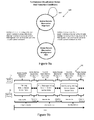
Figure 9a is a state machine diagram of the furtherance visualization states and transition conditions; -
Figure 9b is an example illustration of an initial log and subsequent logs of mobile device vector data over time with mobile device-remote observation alignment, mobile device-remote observation misalignment risk, reconciled alignment and adaptive rendering based upon past known positions provided by mobile device vector data; -
Figure 10 is an example illustration of four different furtherance visualization renderings of a mobile device on a graphical image for a first path segment from point A to point B, a second path segment from point C to point D, a third path segment from point E to point F and a fourth path segment from point G to point H without rendering positional errors; -
Figure 11a is an example illustration of furtherance visualization for a first path segment from point A to point B, including multiple logs of mobile device vector data based upon mobile device-remote observation alignment and potential mobile device-remote observation misalignment risk; -
Figure 11b is an example illustration of furtherance visualization rendering a mobile device on a second path segment from point C to point D, including multiple logs of mobile device vector data based upon mobile device-remote observation alignment and potential mobile device-remote observation misalignment risk; -
Figure 11c is an example illustration of furtherance visualization rendering a mobile device on a third path segment from point E to point F, including multiple logs of mobile device vector data based upon mobile device-remote observation alignment and potential mobile device-remote observation misalignment risk; -
Figure 11d is an example illustration of furtherance visualization rendering a mobile device on a fourth path segment from point G to point H, including multiple logs of mobile device vector data based upon mobile device-remote observation alignment and potential mobile device-remote observation misalignment risk; -
Figure 12a is a flow chart illustrating the logic of a telematics furtherance visualization system process for calibration between the mobile device and the remote device; -
Figure 12b is a flow chart illustrating the logic of a telematics furtherance visualization system process for recalibration between the mobile device and the remote device; -
Figure 13a is a flow chart illustrating the logic of a telematics furtherance visualization system mobile device distributed process; -
Figure 13b is a flow chart of the check reconcile mobile device-remote observation alignment parameters sub process; and -
Figure 14 is a flow chart illustrating the logic of a telematics furtherance visualization system remote device distributed process. - The drawings are not necessarily to scale and may be diagrammatic representations of the exemplary non-limiting embodiments of the present invention.
- Referring to
Figure 1 of the drawings, there is illustrated a high level overview of a telematics communication system. There is at least one mobile device, for example, a vehicle generally indicated at 11. Persons skilled in the art will appreciate other types of mobile devices are within the scope of the invention. Themobile device 11 includes atelemetry hardware system 30 and optionally aresident portion 42. - The telematics communication system provides communication and exchange of data, mobile device vector data, information, commands, and messages between components in the system such as at least one
server 19, at least onecomputing device 20 and at least onemobile device 11. Thecomputing device 20 may be a desktop device or further include other hand held devices or wearable devices. - In one example, the
communication 12 is to/from asatellite 13. Themobile device 11 communicates with thesatellite 13 that communicates with a ground-basedstation 15 that communicates with acomputer network 18. In an embodiment of the invention, the mobiletelemetry hardware system 30 and the remote site 44 (Figure 1 andFigure 2 ) facilitatescommunication 12 to/from thesatellite 13. An example mobile telemetry hardware system 03 is the GEOTAB™ vehicle-tracking device (GO™). - In another example, the
communication 16 is to/from acellular network 17. Themobile device 11, andserver 19 orcomputing device 20 connected to anetwork 18 communicates over thecellular network 17. In an embodiment of the invention,communication 16 to/from thecellular network 17 is facilitated by the mobiletelemetry hardware system 30 and theremote site 44 components. -
Computing device 20 andserver 19 communicate over thecomputer network 18. Theserver 19 may include a database andfleet management software 10 that runs on aserver 19. Clients operating acomputing device 20 communicate with the applicationfleet management software 10 running on theserver 19 orcomputing device 20. Alternative, access to thefleet management software 10 may be provided through cloud computing. An examplefleet management software 10 system is the myGEOTAB™ product. - In an embodiment of the invention, data, mobile device vector data, information, commands, and messages may be sent from the mobile
telemetry hardware system 30 to thecellular network 17, to thenetwork 18, and to theserver 19.Computing devices 20 may access the data, mobile device vector data and information on theserver 19. Alternatively, data, information, commands, and messages may be sent from thecomputing device 20 or theserver 19, to thenetwork 18, to thecellular network 17, and to the mobiletelemetry hardware system 30. - In another embodiment of the invention, data, mobile device vector data, information, commands, and messages may be sent from mobile telemetry hardware system to the
satellite 13, the ground basedstation 15, thenetwork 18, and to theserver 19.Computing devices 20 may access data, mobile device vector data and information on theserver 19. In another embodiment of the invention, data, information, commands, and messages may be sent from theserver 19, to thenetwork 18, the ground basedstation 15, thesatellite 13, and to a mobile telemetry hardware system. - In another embodiment of the invention, data, mobile device vector data, information, commands, and messages may be exchanged between the mobile
telemetry hardware system 30 and thecomputing device 20 over asatellite 13 based network or acellular network 17. Alternatively, the data, mobile device vector data, information, commands, and messages may be exchanged between the mobiletelemetry hardware system 30 and theserver 19 over asatellite 13 based network or acellular network 17. - Referring now to
Figure 2 of the drawings, there is illustrated a mobile telemetry hardware system generally indicated at 30 and a remote site generally indicated at 44. An on-board portion generally includes: a DTE (data terminal equipment)telemetry microprocessor 31; a DCE (data communications equipment) wirelesstelemetry communications microprocessor 32; a GPS (global positioning system)module 33; anaccelerometer 34; anon-volatile flash memory 35; and provision for an OBD (on board diagnostics)interface 36 forconnection 43 and communication with a vehiclenetwork communications bus 37. - The resident
mobile portion 42 generally includes: the vehiclenetwork communications bus 37; the ECM (electronic control module) 38; the PCM (power train control module) 40; the ECUs (electronic control units) 41; and other engine control/monitor computers andmicrocontrollers 39. - While the system is described as having an on-
board portion 30 and a residentmobile portion 42, it is also understood that the present invention could be a complete resident mobile system or a complete on-board system. In addition, in an embodiment of the invention, a mobile telemetry system includes a mobile system and aremote system 44. The mobile system is the mobiletelemetry hardware system 30. The mobiletelemetry hardware system 30 is the on-board portion and may include the residentmobile portion 42. In further embodiments of the invention theremote system 44 may be one or all of theserver 19,computing device 20, andfleet management software 10. - In an embodiment of the invention, the
DTE telemetry microprocessor 31 includes an amount of internal flash memory for storing firmware to operate and control theoverall system 30. In addition, themicroprocessor 31 and firmware log data, log mobile device vector data, format messages, receive messages, and convert or reformat messages. In an embodiment of the invention, an example of aDTE telemetry microprocessor 31 is a PIC24H microcontroller commercially available from Microchip Corporation. - The
DTE telemetry microprocessor 31 interconnects with an externalnon-volatile flash memory 35. In an embodiment of the invention, an example of theflash memory 35 is a 32 MB non-volatile flash memory store commercially available from Atmel Corporation. Theflash memory 35 of the present invention is used for data logging. - The
DTE telemetry microprocessor 31 interconnects for communication to theGPS module 33. In an embodiment of the invention, an example of theGPS module 33 is a Neo-5 commercially available from u-blox Corporation. The Neo-5 provides GPS receiver capability and functionality to the mobiletelemetry hardware system 30. Alternatively, theDTE telemetry microprocessor 31 may interconnect for communication with an external GPS module through an interface (not shown). The GPS module provides position data and speed data to theDTE telemetry microprocessor 31 andnon-volatile flash memory 35. - The DTE telemetry microprocessor is further interconnected with the
OBD interface 36 for communication with the vehiclenetwork communications bus 37. The vehiclenetwork communications bus 37 in turn connects for communication with theECM 38, the engine control/monitor computers andmicrocontrollers 39, thePCM 40, and theECU 41. - The DTE telemetry microprocessor has the ability through the
OBD interface 36 when connected to the vehiclenetwork communications bus 37 to monitor and receive vehicle data and information from the resident mobile system components for further processing. - As a brief non-limiting example of vehicle data and information, the list may include: vehicle identification number (VIN), current odometer reading, current speed, engine RPM, battery voltage, engine coolant temperature, engine coolant level, accelerator pedal position, brake pedal position, various manufacturer specific vehicle DTCs (diagnostic trouble codes), tire pressure, oil level, airbag status, seatbelt indication, emission control data, engine temperature, intake manifold pressure, transmission data, braking information, and fuel level. It is further understood that the amount and type of vehicle data and information will change from manufacturer to manufacturer and evolve with the introduction of additional mobile technology.
- The
DTE telemetry microprocessor 31 interconnects for communication with the DCE wirelesstelemetry communications microprocessor 32. In an embodiment of the invention, an example of the DCE wirelesstelemetry communications microprocessor 32 is aLeon 100 commercially available from u-blox Corporation. TheLeon 100 provides mobile communications capability and functionality to the mobiletelemetry hardware system 30 for sending and receiving data to/from aremote site 44. Alternatively, the communication device could be a satellite communication device such as an Iridium™ device interconnected for communication with theDTE telemetry microprocessor 31. Alternatively, there could be a DCE wirelesstelemetry communications microprocessor 32 and an Iridium™ device for satellite communication. This provides the mobiletelemetry hardware system 30 with the capability to communicate with at least oneremote site 44. - In embodiments of the invention, a
remote system 44 could be anothervehicle 11 or a base station or other computing device (not shown). The base station may include one ormore servers 19 and one ormore computers 20 connected through a computer network 18 (seeFigure 1 ). In addition, the base station may include fleetmanagement application software 10 for data acquisition, analysis, and sending/receiving commands or messages to/from the mobiletelemetry hardware system 30. - The
DTE telemetry microprocessor 31 interconnects for communication with an accelerometer (34). An accelerometer (34) is a device that measures the physical acceleration experienced by an object. Single and multi-axis models of accelerometers are available to detect the magnitude and direction of the acceleration, or g-force, and the device may also be used to sense orientation, coordinate acceleration, vibration, shock, and falling. - In an embodiment of the invention, an example of a multi-axis accelerometer (34) is the LIS302DL MEMS Motion Sensor commercially available from STMicroelectronics. The LIS302DL integrated circuit is an ultra-compact low-power three axes linear accelerometer that includes a sensing element and an IC interface able to take the information from the sensing element and to provide the measured acceleration data to other devices, such as a DTE Telemetry Microprocessor (31), through an I2C/SPI (Inter-Integrated Circuit) (Serial Peripheral Interface) serial interface. The LIS302DL integrated circuit has a user-selectable full-scale range of +-2g and +-8g, programmable thresholds, and is capable of measuring accelerations with an output data rate of 100Hz or 400Hz.
- Alternatively, the
mobile device 30 may not include anintegral GPS module 33 or may not include a DCE wirelesstelemetry communications processor 32. With this alternative embodiment of themobile device 30, an I/O expander (not shown) provides an interface between theDTE telemetry microprocessor 31 and anexternal GPS module 33 or a DCE wirelesstelemetry communications processor 32. - The mobile
telemetry hardware system 30 receives data and information from the residentmobile portion 42, theGPS module 33, and theaccelerometer 43. The data and information is stored innon-volatile flash memory 35 as a data log. The data log (including mobile device vector data) may be transmitted by the mobiletelemetry hardware system 30 over the mobile telemetry communication system to theserver 19 or computing device 20 (seeFigure 1 ). The transmission may be controlled and set by the mobiletelemetry hardware system 30 at pre-defined intervals or aperiodic intervals. The transmission may also be triggered because of an event such as a harsh event or an accident. The transmission may further be requested by a command sent from the application software running on theserver 19. - The
DTE telemetry microprocessor 31 andnon-volatile flash memory 35 cooperate to store and execute the firmware, logic, associated data and mobile device vector data for the telematics furtherance visualization system process (Mobile Device) 280, 290 (seeFigure 13a andFigure 13b ). TheGPS module 33 provides mobile device position data and optionally speed data to theDTE telemetry microprocessor 31 andnon-volatile flash memory 35 for use with the telematics mobile device furtherancevisualization system process 280. Heading data may also be determined and logged. The DCE wirelesstelemetry communications microprocessor 32 provides the communication capability to send initial mobile device vector data to a remote device and subsequent mobile device vector data to aremote system 44. - The
remote system 44 components (server 19, computing device 20) cooperate to access thefleet management software 10. Thefleet management software 10 cooperates to execute the logic and associated data and mobile device vector data for the telematics furtherance visualization system process (Remote Device) 300 (seeFigure 14 ). - Time based positions of a mobile device and potential rendering errors of a
graphical image 54 of a mobile device travelling along apath segment 56 from point A to point B is next described with reference toFigures 3 and4 . - Monitoring a
mobile device 11 occurs by thetelemetry hardware system 30 and associated firmware creating a log of mobile device vector data. A log of mobile device vector data includes at least one data point and mobile device vector data includes at least one of a position (latitude and longitude), speed or heading. Each data point is further associated with a corresponding time stamp. Sequential logs of mobile device vector data are communicated over time to aremote system 44. Upon receipt of the mobile device vector data, theremote system 44 renders a movinggraphical image 54 upon amap 50 of a digital display of acomputing device 20. - In this first example (
Figure 3 ), the mobile device starts at point A and travels along a desiredcurvilinear path segment 56 to the destination point B. For this example, both memory to store data and communication bandwidth are unrestricted and there is a relatively small amount of delay between logging the mobile device vector data and subsequent communication of the log of mobile device vector data to theremote system 44. The time between receipts of sequential logs of mobile device vector data by theremote device 44 is minimal such that a subsequent log is received before rendering the current log is completed. This permits a contiguous rendering based upon the sequential logs of mobile device vector data without the need for adaptive rendering of thegraphical image 54 on amap 50. As themobile device 11 travels along the desiredcurvilinear path segment 56, thegraphical image 54 of themobile device 11 is rendered and updated to reveal the path travelled 52 by themobile device 11 without any associated potential rendering errors for the rendered path travelled 52. - However, memory to store data and communication bandwidth tend to be restricted or limited in telemetry systems due to capacity and expense. As a result, communication of sequential logs of mobile device vector data to the
remote system 44 can be delayed or aperiodic depending upon the techniques to communicate the logs and minimize the timing and amount of communication to reduce cellular or satellite expense. In addition, techniques to compress the mobile device vector data, optimize the mobile device vector data or minimize the data may also render the amount of data points in each log of mobile device vector data different and may introduce aperiodic dependencies. - In a second example (
Figure 4 ), communication of subsequent logs of mobile device vector data may be delayed or aperiodic or contain different amounts of data points in each subsequent log of mobile device vector data. This may introduce a risk for potential rendering errors. A delay in receipt of a subsequent log may cause a misalignment between themobile device 11 and theremote system 44 that renders theimage 54 on a graphical display of theremote device 44. This further requires theremote device 44 to continue rendering positions of themobile device 11 based upon predicting the furtherance or advancement (future or next positions) of amobile device 11 from the current log of mobile device vector data. If theremote device 44 completes rending of themobile device 11 based upon the current log and before receipt of the next subsequent log in the sequence, theremote device 44 must render predicted positions of the mobile device based upon the current log of mobile device vector data or pause rendering thegraphical image 54. - The mobile device begins at point A and travels the desired
curvilinear path segment 56 to the destination point B. Thegraphical image 54 is rendered upon themap 50. Rendering begins along thefirst path portion 62 and due to the communication delay or irregular timing of the communication of a subsequent log of mobile device vector data, a first renderingpositional error 64 occurs. Upon receipt of a subsequent log of mobile device vector data, theremote device 44 corrects the first renderingpositional error 64 and renders the mobile device along thesecond path portion 66. Then, a second rendering positional error 68 occurs due to another communication delay or irregular timing of the communication of a subsequent log of mobile device vector data. Upon receipt of the next log of mobile device vector data in the sequence, theremote device 44 corrects the second rendering positional error 68 and renders the mobile device along the third path portion 70 until the next renderingpositional error 72 occurs and subsequent correction along thenext path portion 74. As illustrated inFigure 4 , the frequency and extent of the risk and associated rending errors is unpredictable and irregular resulting in a deficient representation of the path travelled bymobile device 11 on themap 50. - The different categories, combinations of potential rendering errors and mobile device-remote observation alignment and misalignment risk are next described with reference to
Figures 5, 6a, 6b ,7a, 7b ,8a, 8b ,8c, 8d and8e . - The mobile device furtherance rendered
positions 86 may be accurately predicted and rendered between receipt of subsequent logs of mobiledevice vector data 82 when the change in position of themobile device 11 occurs with a relatively constant speed and relatively constant heading on a relatively linear path segment. This is generally indicated at 80 inFigure 5 . In this situation, the actual mobile device positions 84 are in mobile device-remote observation alignment with the furtherance renderedpositions 86 and the data points in the log of mobiledevice vector data 82 reflect the relatively constant speed and relatively constant heading. Alternatively, the speed and heading may be derived from the data points of positional data to reveal the speed and heading information. - A first type of potential rending error (
Figure 6a ) can occur when themobile device 11 decreases speed on a relatively constant heading or relatively linear path segment. This causes a decreasing speed mobile device-remote observation misalignment 90 over time between the actual mobile device positions 92 and the mobile device furtherance rendered positions 86. The potential error (e1, e2) increases between data points in subsequent logs of mobiledevice vector data 82. - A second type of potential rendering error (
Figure 6b ) can occur when themobile device 11 increases speed on a relatively constant heading or straight path segment. This causes an increasing speed mobile device-remote observation misalignment 100 over time between the actual mobile device positions 102 and the mobile device furtherance rendered positions 86. The potential error (e1, e2) increases between data points in subsequent logs of mobiledevice vector data 82. - A third type of potential rendering error (
Figure 7a ) can occur when themobile device 11 decreases (left or counterclockwise turn) a heading with a relatively constant speed. This causes a decreasing heading mobile device-remote observation misalignment 110 over time between actual mobile device positions 112 and the mobile device furtherance rendered positions 86. The potential error (e1, e2) increases between data points in subsequent logs of mobiledevice vector data 82. - A forth type of potential rendering error (
Figure 7b ) can occur when themobile device 11 increases (right or clockwise turn) a heading with a relatively constant speed. This causes an increasing heading mobile device-remote observation misalignment 120 over time between the actual mobile device positions 122 and the mobile device furtherance rendered positions 86. The potential error (e1, e2) increases between data points in subsequent logs of mobile device vector data. - In summary, there are four distinct types of potential rendering errors that may occur alone or in combinations of speed and heading changes. These potential rendering errors also relate to a transition from a relatively linear path segment to a relatively curved path segment. When the mobile device-remote observation misalignment and potential rendering errors occur in a combination, the error increases faster over time.
- The four distinct types of potential rendering errors along a portion of a path segment can be additionally grouped into categories and combined in different sequences to represent many different path segments as illustrated by the five example scenarios illustrated in
Figures 8a, 8b ,8c, 8d and8e . - The path segment for example scenario one is generally indicated at 130 in
Figure 8a . This path segment example begins with Case B, an area of mobile device-remote observation misalignment risk. This is followed by a transition to a segment of mobile device-remote observation alignment, Case A. Then the path segment concludes with a second occurrence of Case B. Case A occurs for a relatively linear path segment where the speed and heading of themobile device 11 are relatively constant. Case B occurs primarily due to a decreasing heading of themobile device 11. - The path segment for example scenario two is generally indicated at 140 in
Figure 8b . This example path segment begins with Case C, an area of mobile device-remote observation misalignment risk followed by a transition to Case A and a final transition to Case B. Case C occurs primarily due to a increasing heading of themobile device 11. - The path segment for example scenario four is generally indicated at 160 in
Figure 8d . This example path segment begins with Case C followed by a transition to Case A and a final transition to Case C. - The path segment for example scenario five is generally indicated at 170 in
Figure 8C . This example path segment begins with Case D followed by a transition to Case A and a final transition to Case E. Case D is a situation of mobile device-remote observation misalignment risk and occurs primarily due to an increasing speed of themobile device 11. Case E is also a situation of mobile device-remote observation misalignment risk primarily due to the decreasing speed of the mobile device. - In summary, a path segment for a
mobile device 11 may be represented by a combination of one or more of the categories (Case A for mobile device-remote observation alignment, and Case B, C, D, and E for mobile device-remote observation misalignment risk and the associated transitions between the categories. - The category for mobile device-remote observation alignment (Case A), relatively linear path segments, the four categories for misalignment (Case B, C, D, and E) and relatively non-linear path segments may be further associated as transitions between two furtherance visualization states. This is generally illustrated at 180 in
Figure 9a . - The two furtherance visualization states include a mobile device-remote observation alignment state and a mobile device-remote observation misalignment risk state. The initial state is the mobile device-remote observation alignment state. The initial state occurs for example when a
mobile device 11 is stationary. - A state change may occur from mobile device-remote observation alignment to mobile device-remote observation misalignment based upon the operation of the
mobile device 11 over time and upon the path segment. Cases B, C, D, and E over time cause a transition from the mobile device-remote observation alignment state to the mobile device-remote observation misalignment state. This can occur when a position is varying beyond limits, or the speed is increasing or decreasing beyond limits, or the heading is increasing or decreasing beyond limits. This may also occur with combinations of speed and heading changes. A relatively straight path segment and delay in a subsequent log of data over time can also cause a transition to the mobile device-remote observation misalignment state. - The state can also change from mobile device-remote observation misalignment back to mobile device-remote observation alignment based upon the operation of the
mobile device 11 and upon the path segment. Case A or a relatively curved path segment and subsequent log of data can cause over time a transition from the mobile device-remote observation misalignment state to the mobile device-remote observation alignment state. This situation can also occur when a position, speed and heading become relatively constant or varying within limits. - Logging and transmission of mobile device vector data is based upon the furtherance visualization states of mobile device-remote observation alignment and mobile device-remote observation misalignment risk and the transition conditions. Logging and transmission is next described with respect to an initial log, subsequent logs, a potential for a mobile device-remote observation misalignment risk, a reconcile for mobile device-remote observation alignment and an adaptive rendering. This is generally indicated at 190 in
Figure 9b . In addition, four illustrative furtherance rendering examples are described and illustrated inFigures 10 ,11a ,11b ,11c and 11d . - The mobile
telemetry hardware system 30 creates multiple sequential logs of mobile device vector data. These sequential logs are communicated over time to a remote device 44 (seeFigure 9b ) as generally indicated at 190. Furtherance visualization and rendering of agraphical image 54 on amap 50 of aremote device 44 is in mobile device-remote observation alignment with the receipt of the initial log of mobile device vector data. Theremote device 44 performs a data render of thegraphical image 54 based upon the data points and associated time stamps found in the initial log of mobile device vector data. Rending each data point provides furtherance of thegraphical image 54 on themap 50. - The log of mobile device vector data may be based upon different optimization processes. An optimization process can reduce the number of mobile device vector data points in the log. An optimization process can further limit the amount of data communication resulting in aperiodic delays in time concerning transmission and receipt of subsequent logs of mobile device vector data by the
remote device 44. The optimization process can also provide a variable or different amount of data points and associated time stamps per log with relatively regular communication of the logs. The optimization process therefore creates the potential for a mobile device-remote observation misalignment risk. - Adaptive rendering provides an interconnection and transition between the initial log and subsequent logs of mobile device vector data. In an embodiment of the invention, adaptive rendering includes a phase shift between the mobile device time represented by the log of mobile device vector data and remote observation time represented by rendering the
graphical image 54. Mobile device time is based upon GPS time related to the mobile device position in a time zone. Remote observation time is based upon any global time zone related to the remote system and observer. In another embodiment of the invention, adaptive rendering uses the data points from a log when the data is available as a data render. The amount of data points in each log may be different quantity causing a variable data render for each log. During periods of mobile device-remote observation misalignment risk and when the last data point in a log is reached before receipt of the next log of mobile device vector data, in another embodiment of the invention the adaptive rendering can switch to predictive rendering. In an embodiment of the invention, predictive rendering is based upon an extrapolation of the positions, heading and speed associated with the current log of mobile device vector data. A phase shift controls the amount of predictive render required before receipt of subsequent logs of mobile device vector data. Adaptive rendering continues with a data render upon receipt of the next subsequent log of mobile device vector data. - The mobile
telemetry hardware system 30 can sense the risk of a mobile device-remote observation misalignment and send a subsequent log of mobile device vector data to reconcile the mobile device-remote observation misalignment with theremote device 44. Theremote device 44 receives a subsequent log of mobile device vector data and continues the adaptive rendering based upon the subsequent log of mobile device vector data. This process continues through each subsequent receipt a log of mobile device vector data. Adaptive rendering and the reconcile and calibration of mobile device-remote observation alignment is achieved by a coupling of two distributed processes, one located with the mobiletelemetry hardware system 30 and the other located with theremote device 44. The coupling links the logic to sense a misalignment risk and reconcile of the mobile device-remote observation misalignment with the logic to provide a phase shift for the adaptive render. - The first example relates to a
journey event 200 with a mobile device travelling a segment of apath 184 from a starting point A to a destination point B with a mix of linear path segments and curvilinear path segments as illustrated on themap 50 inFigure 10 and11a . In an embodiment of the invention, ajourney event 200 is a portion or segment of a longer or complete journey travelled by themobile device 11. In an alternative embodiment of the invention, ajourney event 200 is the complete journey travelled by themobile device 11. - The
mobile device 11 begins a journey event at point A on thepath 184. An initial log of mobiledevice vector data 82 is transmitted from the mobiletelemetry hardware system 30 to aremote system 44. The log may include one or more data points of mobiledevice vector data 82. Themobile device 11 then enters into a first segment of mobile device-remoteobservation misalignment risk 202. The mobiletelemetry hardware system 30 can sense and determine a mobile device-remote observation misalignment risk. A series of mobile device vector data (204, 206) are logged and transmitted from the mobile devicetelemetry hardware system 30 to aremote system 44 to reconcile the mobile device-remote observation misalignment risk. In an embodiment of the invention, the series of mobile device vector data (204, 206) may be transmitted relatively more frequently in time when in the first segment of mobile device-remoteobservation misalignment risk 202 as compared to a segment of mobile device-remote observation alignment. In another embodiment of the invention, the log may contain a larger sample (higher amount) of mobile device vector data points. - Next, the
mobile device 11 enters into a segment of mobile device-remote observation alignment 208 where the mobiletelemetry hardware system 30 senses mobile device-remote observation alignment. Another log of mobiledevice vector data 85 is created and transmitted from the mobiletelemetry hardware system 30 to aremote system 44. In an embodiment of the invention, the transmission may be relatively less frequent in time when compared to the segment of mobile device-remote observation misalignment risk (202, 214). In another embodiment of the invention, the log may contain a smaller sample of mobile device vector data points. - Next, the
mobile device 11 enters into another segment of mobile device-remoteobservation misalignment risk 214. The mobiletelemetry hardware system 30 again senses and determines a mobile device-remote observation misalignment risk and another series of mobile device vector data (210, 212) are logged and transmitted from the mobile devicetelemetry hardware system 30 to aremote system 44 relatively more frequently in time or with relatively more data points in the log. In an embodiment of the invention, the log may contain a larger sample of mobile device vector data points and associated time stamps. - Then the
mobile device 11 enters into another segment of mobile device-remote observation alignment and completes the journey at point B. Another log of mobiledevice vector data 83 is created and transmitted from the mobiletelemetry hardware system 30 to aremote system 44. - The second example relates to an
exit event 230 where themobile device 11 is travelling apath 186 from point C to point D. Theexit event 230 is a sub-event of a journey event. The exit event occurs where themobile device 11 exits a highway and makes a heading change onto another path segment. The mobiletelemetry hardware system 30 senses theexit event 230 in contrast to a lane change at point C. The path segment includes a mix of linear and curvilinear segments as illustrated inFigure 11b until theexit event 230 completes at point D. - During the
exit event 230, the mobiletelemetry hardware system 30 senses a segment of mobile device-remote observation misalignment risk 222. In an embodiment of the invention, a series of mobile device vector data (224,226) are logged and may be transmitted from the mobile devicetelemetry hardware system 30 to aremote device 44 more frequently in time to reconcile the mobile device-remote observation misalignment. In another embodiment of the invention, the log contains a larger sample of mobile device vector data points communicated less frequently in time. Again, upon receipt of the log of mobile device vector data, theremote device 44 renders the data adaptively to provide agraphical image 54 on amap 50 of theremote device 44. - The third example relates to an
intersection event 240 as illustrated by a mobile device travelling apath 188 from point E to point F. The intersection event is also a sub-event of ajourney event 200. The intersection event example occurs when the mobile device arrives at an intersection and makes a heading change at the intersection. The path includes a mix of linear and curvilinear segments as illustrated inFigure 11c . - Before entering the
intersection event 240, themobile device 11 is in a segment of mobile device-remote observation alignment at point E with a corresponding log of mobiledevice vector data 82 and transmission to aremote system 44. - During the
intersection event 240, the mobiletelemetry hardware system 30 can sense a segment of mobile device-remoteobservation misalignment risk 232. A series of mobile device vector data (234, 236, 238, 242) are logged and may be transmitted from the mobile devicetelemetry hardware system 30 to aremote system 44 relatively more frequently in time. In another embodiment of the invention, the log contains a larger sample of mobile device vector data points communicated less frequently in time. Then, themobile device 11 enters into a segment of mobile device-remote observation alignment at point F. Another log of mobiledevice vector data 83 is created and transmitted from the mobiletelemetry hardware system 30 to aremote system 44. Again, upon receipt of the log of mobile device vector data, theremote device 44 renders the data adaptively to provide agraphical image 54 on amap 50 of theremote device 44. - The fourth example relates to a mobile device travelling a
path 182 from point G to point H where aspeed event 250 occurs. Thespeed event 250 may be a sub event of ajourney event 200 or anexit event 230 or anintersection event 240. Here, the path is a linear segment as illustrated inFigure 11d but alternatively the path segment could be curvilinear or a combination of linear and curvilinear. - Before entering the
speed event 250, themobile device 11 is in a segment of mobile device-remote observation alignment at point G with a corresponding log of mobiledevice vector data 82 and transmission to aremote device 44. - During the
speed event 250, the mobiletelemetry hardware system 30 senses a segment of mobile device-remote observation misalignment risk 220. A series of mobile device vector data (222, 224) are logged and can be transmitted from the mobile devicetelemetry hardware system 30 to aremote device 44 more frequently in time. In an embodiment of the invention, the log contains a larger sample of mobile device vector data points communicated less frequently in time. Then themobile device 11 enters into a segment of mobile device-remote observation alignment at point H and another log of mobiledevice vector data 83 is created and transmitted from the mobiletelemetry hardware system 30 to aremote device 44. Upon receipt of the log of mobile device vector data, theremote device 44 renders the data adaptively to provide agraphical image 54 on amap 50 of theremote device 44. - Sensing mobile device-remote observation misalignment risk can occur in a number of different ways. In an embodiment of the invention, sensing occurs when a heading changes beyond a defined limit triggering the reconcile of mobile device-remote observation alignment. In another embodiment of the invention, sensing occurs when a speed changes beyond a defined limit triggering the reconcile of mobile device-remote observation alignment. In another embodiment of the invention, sensing occurs when a number of raw data points have been sampled triggering a reconcile of mobile device-remote observation alignment.
- Calibration and recalibration of the mobile device furtherance visualization system process is next described with reference to
Figures 12a and12b . - Calibration begins by selecting the furtherance visualization system state transition conditions. The conditions may be based on one or more of the position, speed, heading or portion of a longer path segment (complete journey) represented by a number of raw data points of mobile device vector data. Then, based upon the selected state transition conditions, the reconcile mobile device-remote observation alignment parameters are set for the furtherance visualization system mobile device distributed process. Adaptive render parameters are also based upon the selected transition conditions and correlated to the reconcile mobile device-remote observation alignment parameters are set for the furtherance visualization system remote device distributed process. The correlation provides an appropriate relative mobile device-remote observation timing and phase shift between the furtherance visualization system mobile device distributed process and the the remote device distributed process.
- The furtherance visualization system process may also be recalibrated to further refine or adjust the appropriate relative timing and phase shift. Recalibration begins with a check of the phase shift between the reconcile mobile device-remote observation alignment parameters and the adaptive render parameters. The check determines if the amount of predictive render is acceptable between the receipts of subsequent logs of mobile device vector data. Predictive render is acceptable when the predictive render does not introduce any rendering errors on the
map 50 of a graphical display. If the appropriate timing and phase shift is not acceptable, then recalibrate the reconcile mobile device-remote observation alignment parameters for the furtherance visualization system mobile device distributed process or recalibrate the adaptive render parameters for the mobile device furtherance visualization system remote device distributed process. - For example, in an embodiment of the invention the number of data points in a log of mobile device vector data are reduced by a path simplification process. A log of mobile device vector data is communicated periodically to the remote device. Persons skilled in the art will appreciate there are a number of approaches to reduce the data points representative of a path segment such as the Ramer Douglas Peucker approach, Douglas Peucker approach, iterative end point fit approaches, polyline reductions and split and merge approaches. For this embodiment, the furtherance visualization system state transition conditions are based upon a portion of a path segment and number of raw data points and associated time stamps. The reconcile mobile device-remote observation alignment parameters are then set to a sample of 100 raw data points to define the portion of a path segment travelled by the
mobile device 11 over time for this example embodiment. Sampling of the 100 raw data points is one sample per second. The adaptive render parameters and then set to a range between -4.5 seconds and -13.5 seconds. The adaptive render parameters provide for a phase shift between the distributed processes. Recalibration of the furtherance visualization system process of this embodiment may result in a different set or refinement of the parameters. For example, the adaptive render parameters may be set more precisely to 9.0 seconds to provide better calibration. Alternatively, the sample of 100 raw data points to define the portion of the path segment could be reduced to a smaller sample less than 100 for the reconcile mobile device-remote observation alignment parameters or a larger sample greater than 100 as long as the parameters are calibrated and correlated within the system process. - In another embodiment of the invention, the communication and frequency of logs of mobile device vector data are reduced and based upon events such as the speed and the heading of the
mobile device 11. For a relatively constant speed and heading, the logs are not communicated to theremote device 44. When speed or heading changes beyond a limit, then the log of mobile device vector data is communicated aperiodically to the remote device. The reconcile mobile device-remote observation alignment parameters are set to a speed or heading limit. These limits initiate a reconcile of mobile device-remote observation alignment and communication of a subsequent log of mobile device vector data to a remote device. The adaptive render parameters are then set to a range of time to provide the phase shift between the distributed processes. Recalibration of the furtherance visualization system process for this embodiment may result in a different set of parameters. For example, the adaptive render parameters may be set to more narrow range or precise number in seconds for the phase shift. Alternatively, the speed change limit may be adjusted, or the heading change limit may be adjusted. The recalibration may also be a combination of adjusted or different parameters for both the reconcile mobile device-remote observation alignment or adaptive render parameters. - The first distributed process and furtherance visualization logic and determination of alignment or misalignment risk are next described with reference to
Figures 13a and13b . The mobile device logic is generally illustrated at 280 and the check reconcile mobile device-remote observation alignment parameter logic is generally indicated at 290. - The mobile device furtherance visualization system distributed process is initially calibrated with furtherance visualization reconcile mobile device-remote observation alignment parameters. The furtherance visualization reconcile mobile device-remote observation alignment parameters may also be recalibrated during operation of the process. An initial log of mobile device vector data is communicated from the mobile
telemetry hardware system 30 to aremote device 44. Then, themobile device 11 is monitored and another subsequent log of mobile device vector data is generated and stored in memory of the mobiletelemetry hardware system 30. Themicroprocessor 31 and firmware executing the mobile device furtherance visualization logic is capable to check the reconcile mobile device-remote observation alignment parameters. If the alignment is in mobile device-remote observation alignment, continue to monitor the mobile device and log mobile device vector data. If the alignment is in mobile device-remote observation misalignment risk, then enable a reconciliation for a mobile device-remote observation misalignment risk and communicate the subsequent log of mobile device vector data to aremote system 44. The logic continues and returns to monitor themobile device 11 and log mobile device vector data. - The check for reconcile mobile device-remote observation alignment begins with a determination of the mobile device position. If the position is varying beyond limits, then set mobile device-remote observation misalignment risk. If the position is relatively constant or varying within limits, check the mobile device speed. If the speed is increasing or decreasing beyond limits, set mobile device-remote observation misalignment risk. If the speed is relatively constant or varying within limits, check the mobile device heading. If the heading is increasing or decreasing beyond limits, set mobile device-remote observation misalignment risk. If the heading is relatively constant or varying within limits, set mobile device-remote observation alignment. If the path segment has reached (equal or greater than) the maximum number of raw data points (example of 100 raw data points), then set mobile device-remote observation misalignment risk. If the path segment has not reached (less than) the maximum number of raw data points (example 100 raw data points), then set mobile device-remote observation alignment.
- In an embodiment of the invention, the mobile device parameters of position, speed and heading may be checked in any logical order of position, speed, heading or path segment. In another embodiment of the invention, the check may be one or more of the reconcile mobile device-remote observation alignment parameters (position, or speed, or heading, or path segment) to determine a mobile device-remote observation misalignment risk. Optionally, the mobile device may also communicate a heartbeat message to a remote device. The heartbeat message signals normal operation and alignment of the mobile device to the remote device during longer periods of time between subsequent logs of mobile device vector data.
- The mobile
telemetry hardware system 30 including theDTE telemetry microprocessor 31,non-volatile flash memory 35 and firmware execute the logic of the first distributed process. In embodiments of the invention, theGPS module 33, either integral with the mobiletelemetry hardware system 30 or external to the mobiletelemetry hardware system 30 provide mobile device vector data. Alternatively, mobile device vector data may be provided over the vehiclenetwork communications bus 37 to theinterface 36 to theDTE telemetry microprocessor 31 andnon-volatile flash memory 35. The DCE wirelesstelemetry communications microprocessor 32 integral with the mobiletelemetry hardware system 30 or alternatively an external DCE wirelesstelemetry communications microprocessor 32 provides the capability to communicate mobile device vector data. - The second distributed process and furtherance visualization system logic is next described with reference to
Figure 14 . The remote device furtherance visualization system distributed process is initially calibrated with adaptive render parameters for a phase shift. The adaptive render parameters may also be recalibrated during operation of the process. - The initial log of mobile device vector data is received from the mobile
telemetry hardware system 30. Amobile device 11 is adaptive rendered on a graphical display based upon the sequence of data points and associated time stamps contained in the initial log of mobile device vector data. Then, theremote device 44 receives a subsequent log of mobile device vector data. Themobile device 11 is adaptive rendered on a graphical display based upon the sequence of data points contained in the subsequent log of mobile device vector data and the phase shift. The process repeats for each receipt of subsequent logs of mobile device vector data. - In an embodiment of the invention, the adaptive render is a phase shift. In another embodiment of the invention, the adaptive render includes a data render. In another embodiment of the invention, the adaptive render includes a predictive render. The phase shift is calibrated to reduce the amount of predictive render or to limit the amount of mobile device-remote observation misalignment risk.
- A microprocessor and memory on the
server 19, or thecomputing device 20 execute the logic of the second distributed process. The second distributed process may also be incorporated into a fleetmanagement software program 10 that executes on aserver 19 or acomputing device 20. - Embodiments of the present invention provide one or more technical effects. More specifically, an ability to maintain a mobile device-remote observation alignment between a mobile device and a remote device for receiving logs of mobile device vector data and rendering a graphical image of the mobile device on a graphics display. Another ability to sense a mobile device-remote observation misalignment risk between the mobile device and the remote device and communication of a log of mobile device vector data to reconcile mobile device-remote observation alignment. An adaptive render with a calibrated phase shift including the ability to render based upon data from the log of mobile device vector data and the ability to render predictively when required until receipt of a subsequent log of mobile device vector data. Another ability to calibrate the adaptive render with the reconcile mobile device-remote observation alignment to minimize the predictive render when required.
- The description of present invention is with respect to the disclosed non-limiting embodiments and persons skilled in the art understand that the invention is not limited to the disclosed non-limiting embodiments. Persons skilled in the art further understand that the disclosed invention intends to cover various modifications and equivalent arrangements included within the scope of the appended claims. Thus, the present invention is not limited by any of the described non-limiting embodiments.
Claims (22)
- A telematics furtherance visualization method comprising:a first distributed process for a mobile device,a second distributed process for a remote device, said first distributed process and said second distributed process capable of communicating messages and data,said first distributed process capable to monitor said mobile device to log and communicate mobile device vector data to said remote device, said first distributed process capable to sense a mobile device remote observation misalignment risk and reconcile mobile device remote observation alignment, andsaid second distributed process capable to adaptive render a graphical image of said mobile device from said mobile device vector data.
- A telematics furtherance visualization method as in claim 1 wherein said mobile device remote observation misalignment risk includes mobile device remote observation alignment parameters,
and wherein said adaptive render includes adaptive render parameters, and
said mobile device remote observation alignment parameters and said adaptive render parameters are correlated. - A telematics furtherance visualization method as in claim 1 wherein said reconcile mobile device remote observation alignment includes communicating a subsequent log of said mobile device vector data.
- A telematics furtherance visualization method as in claim 2 wherein said mobile device remote observation alignment parameters are based upon at least one of a position limit, a speed limit, a heading limit or a path segment limit.
- A telematics furtherance visualization method as in claim 2 wherein said mobile device remote observation alignment parameters and said adaptive render parameters are correlated or calibrated to command a predictive render.
- A telematics furtherance visualization method as in claim 2 wherein said capable to sense a potential mobile device remote observation misalignment risk is based upon checking said mobile device remote observation alignment parameters.
- A telematics furtherance visualization method as in claim 6 wherein said checking said mobile device remote observation alignment parameters enables said reconcile mobile device remote observation alignment.
- A telematics furtherance visualization method as in claim 2 wherein said capable to adaptive render is based upon said adaptive render parameters.
- A telematics furtherance visualization method as in claim 6 wherein said checking said mobile device remote observation alignment parameters determines a mobile device remote observation misalignment risk based upon a position varying beyond a limit, a speed limit, a heading limit or a path segment represented by a number of raw data points.
- A telematics furtherance visualization method as in claim 2 wherein said mobile device remote observation alignment parameters and said adaptive render parameters may be recalibrated, wherein said recalibrated is at least one of said mobile device remote observation alignment parameters or said adaptive render parameters.
- A telematics furtherance visualization method as in claims 3 or 5 further including a heartbeat to further command a predictive render.
- A telematics furtherance visualization apparatus comprising:at least one mobile device,said at least one mobile device including a microprocessor, memory and firmware,said microprocessor, memory and firmware capable of executing a first distributed process, at least one remote device,said at least one remote device including a microprocessor, memory and software,said microprocessor, memory and software capable of executing a second distributed process,said at least one mobile device and said at least one remote device capable of communication,a first distributed process for a mobile device,a second distributed process for a remote device, said first distributed process and said second distributed process capable of communicating messages and data,said first distributed process capable to monitor said mobile device to log and communicate mobile device vector data to said remote device, said first distributed process capable to sense a mobile device remote observation misalignment risk and reconcile mobile device remote observation alignment, andsaid second distributed process capable to adaptive render a graphical image of said mobile device from said mobile device vector data.
- A telematics furtherance visualization apparatus as in claim 12 wherein said mobile device remote observation misalignment risk includes mobile device remote observation alignment parameters,
and wherein said adaptive render includes adaptive render parameters, and said mobile device remote observation alignment parameters and said adaptive render parameters are correlated. - A telematics furtherance visualization apparatus as in claim 12 wherein said reconcile mobile device remote observation alignment includes communicating a subsequent log of said mobile device vector data.
- A telematics furtherance visualization apparatus as in claim 13 wherein said mobile device remote observation alignment parameters are based upon at least one of a position limit, a speed limit, a heading limit or a path segment limit.
- A telematics furtherance visualization apparatus as in claim 13 wherein said mobile device remote observation alignment parameters and said adaptive render parameters are correlated or calibrated to command a predictive render.
- A telematics furtherance visualization apparatus as in claim 13 wherein said capable to sense a potential mobile device remote observation misalignment risk is based upon checking said mobile device remote observation alignment parameters.
- A telematics furtherance visualization apparatus as in claim 17 wherein said checking said mobile device remote observation alignment parameters enables said reconcile mobile device remote observation alignment.
- A telematics furtherance visualization apparatus as in claim 13 wherein said capable to adaptive render is based upon said adaptive render parameters.
- A telematics furtherance visualization apparatus as in claim 17 wherein said checking said mobile device remote observation alignment parameters determine a mobile device remote observation misalignment risk based upon a position varying beyond a limit, a speed limit, a heading limit or a path segment represented by a number of raw data points.
- A telematics furtherance visualization apparatus as in claim 13 wherein said mobile device remote observation alignment parameters and said adaptive render parameters may be recalibrated, wherein said recalibrated is at least one of said mobile device remote observation alignment parameters or said adaptive render parameters.
- A telematics furtherance visualization apparatus as in claims 14 or 16 further including a heartbeat to further command a predictive render.
Priority Applications (1)
| Application Number | Priority Date | Filing Date | Title |
|---|---|---|---|
| PL15160481T PL3048584T3 (en) | 2015-01-15 | 2015-03-24 | Visualisation of the position of a mobile device |
Applications Claiming Priority (1)
| Application Number | Priority Date | Filing Date | Title |
|---|---|---|---|
| US14/597,667 US9538334B2 (en) | 2015-01-15 | 2015-01-15 | Telematics furtherance visualization system |
Publications (2)
| Publication Number | Publication Date |
|---|---|
| EP3048584A1 true EP3048584A1 (en) | 2016-07-27 |
| EP3048584B1 EP3048584B1 (en) | 2021-07-21 |
Family
ID=53052656
Family Applications (1)
| Application Number | Title | Priority Date | Filing Date |
|---|---|---|---|
| EP15160481.6A Active EP3048584B1 (en) | 2015-01-15 | 2015-03-24 | Visualisation of the position of a mobile device |
Country Status (4)
| Country | Link |
|---|---|
| US (6) | US9538334B2 (en) |
| EP (1) | EP3048584B1 (en) |
| ES (1) | ES2900828T3 (en) |
| PL (1) | PL3048584T3 (en) |
Families Citing this family (26)
| Publication number | Priority date | Publication date | Assignee | Title |
|---|---|---|---|---|
| KR101477692B1 (en) * | 2012-11-23 | 2015-01-02 | 주식회사 투게더 | The system and the method for recording visiting data of a wireless communication device |
| JP6323565B2 (en) * | 2014-10-22 | 2018-05-16 | 日産自動車株式会社 | Driving assistance device |
| US9538334B2 (en) | 2015-01-15 | 2017-01-03 | GEOTAB Incorporated | Telematics furtherance visualization system |
| US9644972B2 (en) * | 2015-03-06 | 2017-05-09 | Tallysman Wireless Inc. | Method for tracking a path taken by a vehicle |
| US9686767B2 (en) * | 2015-08-24 | 2017-06-20 | Qualcomm Incorporated | Device, method, and system for determining location |
| US9749470B1 (en) * | 2016-01-27 | 2017-08-29 | State Farm Mutual Automobile Insurance Company | Systems and methods for handling communications during user operation of a motor vehicle |
| US11073400B2 (en) | 2017-11-07 | 2021-07-27 | Uatc, Llc | Map creation from hybrid data |
| US10730521B2 (en) * | 2017-12-21 | 2020-08-04 | Denso International America, Inc. | System for autonomous lane merging |
| US11396297B2 (en) * | 2018-02-26 | 2022-07-26 | Honda Motor Co., Ltd. | Vehicle control system, vehicle control method, and program |
| JP7119428B2 (en) * | 2018-03-02 | 2022-08-17 | 株式会社デンソー | Driving support device |
| CN109345827A (en) * | 2018-10-22 | 2019-02-15 | 重庆工业职业技术学院 | A kind of urban transportation Bus information delivery system and method based on Internet of Things |
| JP7256982B2 (en) | 2018-12-28 | 2023-04-13 | スズキ株式会社 | Vehicle travel control device |
| JP7189509B2 (en) * | 2019-03-27 | 2022-12-14 | スズキ株式会社 | Vehicle travel control device |
| CN111325993B (en) * | 2019-04-24 | 2021-02-19 | 北京嘀嘀无限科技发展有限公司 | Traffic speed determination method and device, electronic equipment and computer storage medium |
| JP7316542B2 (en) * | 2019-05-21 | 2023-07-28 | スズキ株式会社 | Vehicle running control device |
| JP7393730B2 (en) | 2019-09-26 | 2023-12-07 | スズキ株式会社 | Vehicle travel control device |
| DE102020000593A1 (en) * | 2020-01-30 | 2021-08-05 | Daimler Ag | Method for operating an assistance system |
| KR20210130324A (en) * | 2020-04-21 | 2021-11-01 | 현대자동차주식회사 | Advanced Driver Assistance System, Vehicle having the same and method for controlling the vehicle |
| US11022444B1 (en) | 2020-06-16 | 2021-06-01 | Geotab Inc. | Dataset simplification of multidimensional signals captured for asset tracking |
| JP7351805B2 (en) * | 2020-07-01 | 2023-09-27 | トヨタ自動車株式会社 | Information processing method, program, in-vehicle device, and vehicle |
| US11556509B1 (en) | 2020-07-31 | 2023-01-17 | Geotab Inc. | Methods and devices for fixed interpolation error data simplification processes for telematic |
| US11593329B2 (en) * | 2020-07-31 | 2023-02-28 | Geotab Inc. | Methods and devices for fixed extrapolation error data simplification processes for telematics |
| US11609888B2 (en) | 2020-07-31 | 2023-03-21 | Geotab Inc. | Methods and systems for fixed interpolation error data simplification processes for telematics |
| US11546395B2 (en) | 2020-11-24 | 2023-01-03 | Geotab Inc. | Extrema-retentive data buffering and simplification |
| US11838364B2 (en) | 2020-11-24 | 2023-12-05 | Geotab Inc. | Extrema-retentive data buffering and simplification |
| KR20230021457A (en) * | 2021-08-05 | 2023-02-14 | 현대모비스 주식회사 | Obstacle detecting system and method for vehicle |
Citations (10)
| Publication number | Priority date | Publication date | Assignee | Title |
|---|---|---|---|---|
| US20010047244A1 (en) | 1996-09-16 | 2001-11-29 | Minorplanet Limited. | Monitoring vehicle positions |
| US20040039504A1 (en) * | 1999-12-19 | 2004-02-26 | Fleet Management Services, Inc. | Vehicle tracking, communication and fleet management system |
| US6845318B1 (en) | 2003-04-09 | 2005-01-18 | Garmin Ltd. | Methods, data structures, and systems for processing track logs |
| US8032276B2 (en) | 2004-12-07 | 2011-10-04 | Geotab, Inc. | Apparatus and method for optimally recording geographical position data |
| EP2407950A2 (en) * | 2010-07-16 | 2012-01-18 | Research In Motion Limited | Gps trace filtering |
| US20120253862A1 (en) | 2011-03-31 | 2012-10-04 | United Parcel Service Of America, Inc. | Systems and methods for providing a fleet management user interface |
| US20120303266A1 (en) | 2011-05-23 | 2012-11-29 | Microsoft Corporation | First waypoint distance |
| US20140024354A1 (en) * | 2012-07-18 | 2014-01-23 | Microsoft Corporation | Prediction for power conservation in a mobile device |
| US8706348B2 (en) | 2004-12-13 | 2014-04-22 | Geotab | Apparatus, system and method utilizing aperiodic nonrandom triggers for vehicular telematics data queries |
| WO2014145409A1 (en) * | 2013-03-15 | 2014-09-18 | Cambridge Mobile Telematics | Inference of vehicular trajectory characteristics with personal mobile devices |
Family Cites Families (50)
| Publication number | Priority date | Publication date | Assignee | Title |
|---|---|---|---|---|
| US8036788B2 (en) * | 1995-06-07 | 2011-10-11 | Automotive Technologies International, Inc. | Vehicle diagnostic or prognostic message transmission systems and methods |
| US8965677B2 (en) * | 1998-10-22 | 2015-02-24 | Intelligent Technologies International, Inc. | Intra-vehicle information conveyance system and method |
| US8209120B2 (en) * | 1997-10-22 | 2012-06-26 | American Vehicular Sciences Llc | Vehicular map database management techniques |
| US7647180B2 (en) * | 1997-10-22 | 2010-01-12 | Intelligent Technologies International, Inc. | Vehicular intersection management techniques |
| US7983802B2 (en) * | 1997-10-22 | 2011-07-19 | Intelligent Technologies International, Inc. | Vehicular environment scanning techniques |
| US10358057B2 (en) * | 1997-10-22 | 2019-07-23 | American Vehicular Sciences Llc | In-vehicle signage techniques |
| US8068979B2 (en) * | 1997-10-22 | 2011-11-29 | Intelligent Technologies International, Inc. | Inattentive vehicular operator detection method and arrangement |
| US8630795B2 (en) * | 1999-03-11 | 2014-01-14 | American Vehicular Sciences Llc | Vehicle speed control method and arrangement |
| ES2284862T3 (en) * | 2001-02-09 | 2007-11-16 | Yosef Mintz | IMPROVED PROCEDURE AND SYSTEM TO CARTOGRAPH TRAFFIC PREDICTIONS WITH REGARD TO TELEMATIC AND ROUTE ORIENTATION APPLICATIONS. |
| US20030036823A1 (en) * | 2001-08-15 | 2003-02-20 | A. Pascal Mahvi | Method and system for a vehicle monitoring and control system |
| US8977284B2 (en) * | 2001-10-04 | 2015-03-10 | Traxcell Technologies, LLC | Machine for providing a dynamic data base of geographic location information for a plurality of wireless devices and process for making same |
| US20130267194A1 (en) * | 2002-06-11 | 2013-10-10 | American Vehicular Sciences Llc | Method and System for Notifying a Remote Facility of an Accident Involving a Vehicle |
| US6832153B2 (en) * | 2002-11-27 | 2004-12-14 | Mobilearia | Method and apparatus for providing information pertaining to vehicles located along a predetermined travel route |
| KR100546480B1 (en) * | 2003-03-28 | 2006-01-26 | 에스케이 텔레콤주식회사 | Method for obtaining traffic information by using call data record of mobile |
| US7397351B1 (en) * | 2005-07-20 | 2008-07-08 | Bae Systems Information And Electronic Systems Integration Inc. | Use of E-field sensors for situation awareness/collision avoidance |
| US20080294690A1 (en) * | 2007-05-22 | 2008-11-27 | Mcclellan Scott | System and Method for Automatically Registering a Vehicle Monitoring Device |
| WO2008044375A1 (en) * | 2006-10-12 | 2008-04-17 | Mitsubishi Electric Corporation | Map information processing device |
| JP2008309529A (en) * | 2007-06-12 | 2008-12-25 | Panasonic Corp | Navigation system, navigation method and program for navigation |
| US20090140887A1 (en) * | 2007-11-29 | 2009-06-04 | Breed David S | Mapping Techniques Using Probe Vehicles |
| US8022831B1 (en) * | 2008-01-03 | 2011-09-20 | Pamela Wood-Eyre | Interactive fatigue management system and method |
| ES2387772T3 (en) * | 2008-03-11 | 2012-10-01 | Gmv Aerospace And Defence S.A. | Map georeferencing procedure ("map matching") with guaranteed integrity |
| US20100211249A1 (en) * | 2009-02-13 | 2010-08-19 | Mcclellan Scott | System and method for detecting vehicle maintenance requirements |
| US9655419B2 (en) * | 2010-09-07 | 2017-05-23 | Michael J. Nash | Data signal blocking personal communication device holder |
| US9615476B2 (en) * | 2011-06-13 | 2017-04-04 | Treefrog Developments, Inc. | Housing for encasing a mobile device |
| CN105843331B (en) * | 2011-06-13 | 2019-06-14 | 树蛙开发公司 | For protecting the shell of tablet computer |
| US9795044B2 (en) * | 2011-08-22 | 2017-10-17 | Catalyst Lifestyle Limited | Waterproof case |
| WO2013078060A1 (en) * | 2011-11-23 | 2013-05-30 | Speculative Product Design, Llc | Case for enclosing a personal electronic device |
| US9595209B2 (en) * | 2011-12-13 | 2017-03-14 | Telenav, Inc. | Navigation system with map matching mechanism and method of operation thereof |
| US8594755B1 (en) * | 2012-05-03 | 2013-11-26 | A.G. Findings & Mfg. Co., Inc. | Mobile device case with a screen protector |
| US20130292378A1 (en) * | 2012-05-04 | 2013-11-07 | A.G. Findings & Mfg. Co., Inc. | Mobile device case having integrated latch |
| US9060580B2 (en) * | 2012-05-04 | 2015-06-23 | A.G. Findings & Mfg. Co., Inc. | Mobile device case having tension elements |
| JP5966691B2 (en) * | 2012-07-05 | 2016-08-10 | 日産自動車株式会社 | Vehicle control system, server, and vehicle control device |
| US8716598B2 (en) * | 2012-08-23 | 2014-05-06 | Octo Products LLC | Case for housing and protecting an electronic device |
| US9239590B2 (en) * | 2013-02-15 | 2016-01-19 | Infinite Peripherals | Apparatus comprising a pistol grip |
| US9184778B2 (en) * | 2013-02-22 | 2015-11-10 | Nissan North America, Inc. | Vehicle information gathering system |
| US9809169B1 (en) * | 2013-03-15 | 2017-11-07 | Mouhamad A. Naboulsi | Safety control system for vehicles |
| CN107533801A (en) * | 2013-11-01 | 2018-01-02 | 国际智能技术公司 | Use the ground mapping technology of mapping vehicle |
| WO2016099443A1 (en) * | 2014-12-15 | 2016-06-23 | Intelligent Technologies International, Inc. | Mapping techniques using probe vehicles |
| US10429408B2 (en) * | 2014-06-04 | 2019-10-01 | Danlaw Inc. | Vehicle monitoring module |
| US9286679B2 (en) * | 2014-07-22 | 2016-03-15 | GM Global Technology Operations LLC | Misalignment correction and state of health estimation for lane management fusion function |
| US20160084661A1 (en) * | 2014-09-23 | 2016-03-24 | GM Global Technology Operations LLC | Performance driving system and method |
| FR3030091B1 (en) * | 2014-12-12 | 2018-01-26 | Airbus Operations | METHOD AND SYSTEM FOR AUTOMATICALLY DETECTING A DISALLIATION IN OPERATION OF A MONITORING SENSOR OF AN AIRCRAFT. |
| CN105813423B (en) * | 2014-12-29 | 2019-10-22 | 深圳富泰宏精密工业有限公司 | Shell and preparation method thereof, the electronic device using the shell |
| US9538334B2 (en) | 2015-01-15 | 2017-01-03 | GEOTAB Incorporated | Telematics furtherance visualization system |
| US10551196B2 (en) * | 2015-04-30 | 2020-02-04 | Raytheon Company | Sensor installation monitoring |
| US10114126B2 (en) * | 2015-04-30 | 2018-10-30 | Raytheon Company | Sensor installation monitoring |
| US11107365B1 (en) * | 2015-08-28 | 2021-08-31 | State Farm Mutual Automobile Insurance Company | Vehicular driver evaluation |
| US10089878B2 (en) * | 2015-10-09 | 2018-10-02 | MDR Manufacturing Corporation | Wrong way alert |
| US9773421B2 (en) * | 2015-10-19 | 2017-09-26 | Honeywell International Inc. | Aircraft maneuver data management system |
| KR102614495B1 (en) * | 2019-08-02 | 2023-12-15 | 엘지전자 주식회사 | Xr device and method for controlling the same |
-
2015
- 2015-01-15 US US14/597,667 patent/US9538334B2/en active Active
- 2015-03-24 EP EP15160481.6A patent/EP3048584B1/en active Active
- 2015-03-24 PL PL15160481T patent/PL3048584T3/en unknown
- 2015-03-24 ES ES15160481T patent/ES2900828T3/en active Active
-
2016
- 2016-11-02 US US15/341,842 patent/US9775004B2/en active Active
-
2017
- 2017-08-22 US US15/682,615 patent/US9913101B2/en active Active
-
2018
- 2018-01-16 US US15/872,316 patent/US10051432B2/en active Active
- 2018-06-28 US US16/021,081 patent/US10623904B2/en active Active
-
2020
- 2020-03-27 US US16/832,383 patent/US11153718B2/en active Active
Patent Citations (11)
| Publication number | Priority date | Publication date | Assignee | Title |
|---|---|---|---|---|
| US20010047244A1 (en) | 1996-09-16 | 2001-11-29 | Minorplanet Limited. | Monitoring vehicle positions |
| US20040039504A1 (en) * | 1999-12-19 | 2004-02-26 | Fleet Management Services, Inc. | Vehicle tracking, communication and fleet management system |
| US6845318B1 (en) | 2003-04-09 | 2005-01-18 | Garmin Ltd. | Methods, data structures, and systems for processing track logs |
| US8032276B2 (en) | 2004-12-07 | 2011-10-04 | Geotab, Inc. | Apparatus and method for optimally recording geographical position data |
| US8670928B2 (en) | 2004-12-07 | 2014-03-11 | Geotab, Inc. | Apparatus and method for optimally recording geographical position data |
| US8706348B2 (en) | 2004-12-13 | 2014-04-22 | Geotab | Apparatus, system and method utilizing aperiodic nonrandom triggers for vehicular telematics data queries |
| EP2407950A2 (en) * | 2010-07-16 | 2012-01-18 | Research In Motion Limited | Gps trace filtering |
| US20120253862A1 (en) | 2011-03-31 | 2012-10-04 | United Parcel Service Of America, Inc. | Systems and methods for providing a fleet management user interface |
| US20120303266A1 (en) | 2011-05-23 | 2012-11-29 | Microsoft Corporation | First waypoint distance |
| US20140024354A1 (en) * | 2012-07-18 | 2014-01-23 | Microsoft Corporation | Prediction for power conservation in a mobile device |
| WO2014145409A1 (en) * | 2013-03-15 | 2014-09-18 | Cambridge Mobile Telematics | Inference of vehicular trajectory characteristics with personal mobile devices |
Also Published As
| Publication number | Publication date |
|---|---|
| US10051432B2 (en) | 2018-08-14 |
| US9538334B2 (en) | 2017-01-03 |
| US20180317051A1 (en) | 2018-11-01 |
| US10623904B2 (en) | 2020-04-14 |
| US20180160272A1 (en) | 2018-06-07 |
| US9913101B2 (en) | 2018-03-06 |
| US20210051441A1 (en) | 2021-02-18 |
| US20170156037A1 (en) | 2017-06-01 |
| ES2900828T3 (en) | 2022-03-18 |
| EP3048584B1 (en) | 2021-07-21 |
| PL3048584T3 (en) | 2022-01-10 |
| US20170374527A1 (en) | 2017-12-28 |
| US20160212589A1 (en) | 2016-07-21 |
| US11153718B2 (en) | 2021-10-19 |
| US9775004B2 (en) | 2017-09-26 |
Similar Documents
| Publication | Publication Date | Title |
|---|---|---|
| US11153718B2 (en) | Telematics furtherance visualization system | |
| US10102689B2 (en) | Systems and methods for location reporting of detected events in vehicle operation | |
| WO2016110915A1 (en) | In-vehicle unit and in-vehicle unit diagnosis system | |
| JP6845896B2 (en) | High-precision time stamp generation circuit based on GPS for self-driving vehicles | |
| EP2836790B1 (en) | Method and system for recording and transmitting data from a mobile asset | |
| KR102399488B1 (en) | Flexible Test Board to Improve Sensor I/O Coverage for Autonomous Driving Platform | |
| KR20140119119A (en) | Apparatus, system and method for risk indicator calculation for driving behaviour and for reconstructing a vehicle trajectory | |
| CN110895147A (en) | Image data acquisition logic for an autonomous vehicle that captures image data with a camera | |
| US11523292B2 (en) | Mobile device protocol health monitoring system | |
| CN202243556U (en) | Passenger transport line running data collecting and analyzing system based on ARM embedded system | |
| US20230128379A1 (en) | Method and device for evaluating a function for predicting a trajectory of an object in an environment of a vehicle | |
| US20200402396A1 (en) | Method, device and system for wrong-way driver detection | |
| KR101688808B1 (en) | A Verifying Method Of Digital Tachograph Of Vehicle | |
| WO2014108219A1 (en) | Apparatus, system and method for vehicle trajectory reconstruction | |
| US20230177952A1 (en) | A system and method for generating utilization data of a vehicle | |
| KR101609791B1 (en) | A Verifying Method Of Digital Tachograph Of Vehicle | |
| JP2021015464A (en) | Apparatus diagnosis device, apparatus diagnosis system and apparatus diagnosis method | |
| CA3201927A1 (en) | A mount security detection method |
Legal Events
| Date | Code | Title | Description |
|---|---|---|---|
| PUAI | Public reference made under article 153(3) epc to a published international application that has entered the european phase |
Free format text: ORIGINAL CODE: 0009012 |
|
| AK | Designated contracting states |
Kind code of ref document: A1 Designated state(s): AL AT BE BG CH CY CZ DE DK EE ES FI FR GB GR HR HU IE IS IT LI LT LU LV MC MK MT NL NO PL PT RO RS SE SI SK SM TR |
|
| AX | Request for extension of the european patent |
Extension state: BA ME |
|
| STAA | Information on the status of an ep patent application or granted ep patent |
Free format text: STATUS: REQUEST FOR EXAMINATION WAS MADE |
|
| 17P | Request for examination filed |
Effective date: 20170113 |
|
| RBV | Designated contracting states (corrected) |
Designated state(s): AL AT BE BG CH CY CZ DE DK EE ES FI FR GB GR HR HU IE IS IT LI LT LU LV MC MK MT NL NO PL PT RO RS SE SI SK SM TR |
|
| RAP1 | Party data changed (applicant data changed or rights of an application transferred) |
Owner name: GEOTAB INC. |
|
| STAA | Information on the status of an ep patent application or granted ep patent |
Free format text: STATUS: EXAMINATION IS IN PROGRESS |
|
| 17Q | First examination report despatched |
Effective date: 20190705 |
|
| STAA | Information on the status of an ep patent application or granted ep patent |
Free format text: STATUS: EXAMINATION IS IN PROGRESS |
|
| GRAP | Despatch of communication of intention to grant a patent |
Free format text: ORIGINAL CODE: EPIDOSNIGR1 |
|
| STAA | Information on the status of an ep patent application or granted ep patent |
Free format text: STATUS: GRANT OF PATENT IS INTENDED |
|
| RIC1 | Information provided on ipc code assigned before grant |
Ipc: G07C 5/00 20060101AFI20210310BHEP Ipc: G07B 15/00 20110101ALI20210310BHEP Ipc: G01C 21/20 20060101ALI20210310BHEP Ipc: H04W 4/029 20180101ALI20210310BHEP Ipc: H04W 4/02 20180101ALI20210310BHEP Ipc: G08G 1/00 20060101ALI20210310BHEP Ipc: G08G 1/052 20060101ALI20210310BHEP Ipc: G08G 1/01 20060101ALI20210310BHEP Ipc: G01C 21/36 20060101ALI20210310BHEP |
|
| INTG | Intention to grant announced |
Effective date: 20210408 |
|
| GRAS | Grant fee paid |
Free format text: ORIGINAL CODE: EPIDOSNIGR3 |
|
| GRAA | (expected) grant |
Free format text: ORIGINAL CODE: 0009210 |
|
| STAA | Information on the status of an ep patent application or granted ep patent |
Free format text: STATUS: THE PATENT HAS BEEN GRANTED |
|
| AK | Designated contracting states |
Kind code of ref document: B1 Designated state(s): AL AT BE BG CH CY CZ DE DK EE ES FI FR GB GR HR HU IE IS IT LI LT LU LV MC MK MT NL NO PL PT RO RS SE SI SK SM TR |
|
| REG | Reference to a national code |
Ref country code: GB Ref legal event code: FG4D |
|
| REG | Reference to a national code |
Ref country code: CH Ref legal event code: EP |
|
| REG | Reference to a national code |
Ref country code: DE Ref legal event code: R096 Ref document number: 602015071421 Country of ref document: DE |
|
| REG | Reference to a national code |
Ref country code: AT Ref legal event code: REF Ref document number: 1413291 Country of ref document: AT Kind code of ref document: T Effective date: 20210815 |
|
| REG | Reference to a national code |
Ref country code: IE Ref legal event code: FG4D |
|
| REG | Reference to a national code |
Ref country code: NL Ref legal event code: FP |
|
| REG | Reference to a national code |
Ref country code: LT Ref legal event code: MG9D |
|
| REG | Reference to a national code |
Ref country code: AT Ref legal event code: MK05 Ref document number: 1413291 Country of ref document: AT Kind code of ref document: T Effective date: 20210721 |
|
| PG25 | Lapsed in a contracting state [announced via postgrant information from national office to epo] |
Ref country code: PT Free format text: LAPSE BECAUSE OF FAILURE TO SUBMIT A TRANSLATION OF THE DESCRIPTION OR TO PAY THE FEE WITHIN THE PRESCRIBED TIME-LIMIT Effective date: 20211122 Ref country code: NO Free format text: LAPSE BECAUSE OF FAILURE TO SUBMIT A TRANSLATION OF THE DESCRIPTION OR TO PAY THE FEE WITHIN THE PRESCRIBED TIME-LIMIT Effective date: 20211021 Ref country code: FI Free format text: LAPSE BECAUSE OF FAILURE TO SUBMIT A TRANSLATION OF THE DESCRIPTION OR TO PAY THE FEE WITHIN THE PRESCRIBED TIME-LIMIT Effective date: 20210721 Ref country code: LT Free format text: LAPSE BECAUSE OF FAILURE TO SUBMIT A TRANSLATION OF THE DESCRIPTION OR TO PAY THE FEE WITHIN THE PRESCRIBED TIME-LIMIT Effective date: 20210721 Ref country code: AT Free format text: LAPSE BECAUSE OF FAILURE TO SUBMIT A TRANSLATION OF THE DESCRIPTION OR TO PAY THE FEE WITHIN THE PRESCRIBED TIME-LIMIT Effective date: 20210721 Ref country code: BG Free format text: LAPSE BECAUSE OF FAILURE TO SUBMIT A TRANSLATION OF THE DESCRIPTION OR TO PAY THE FEE WITHIN THE PRESCRIBED TIME-LIMIT Effective date: 20211021 Ref country code: RS Free format text: LAPSE BECAUSE OF FAILURE TO SUBMIT A TRANSLATION OF THE DESCRIPTION OR TO PAY THE FEE WITHIN THE PRESCRIBED TIME-LIMIT Effective date: 20210721 Ref country code: SE Free format text: LAPSE BECAUSE OF FAILURE TO SUBMIT A TRANSLATION OF THE DESCRIPTION OR TO PAY THE FEE WITHIN THE PRESCRIBED TIME-LIMIT Effective date: 20210721 Ref country code: HR Free format text: LAPSE BECAUSE OF FAILURE TO SUBMIT A TRANSLATION OF THE DESCRIPTION OR TO PAY THE FEE WITHIN THE PRESCRIBED TIME-LIMIT Effective date: 20210721 |
|
| PG25 | Lapsed in a contracting state [announced via postgrant information from national office to epo] |
Ref country code: LV Free format text: LAPSE BECAUSE OF FAILURE TO SUBMIT A TRANSLATION OF THE DESCRIPTION OR TO PAY THE FEE WITHIN THE PRESCRIBED TIME-LIMIT Effective date: 20210721 Ref country code: GR Free format text: LAPSE BECAUSE OF FAILURE TO SUBMIT A TRANSLATION OF THE DESCRIPTION OR TO PAY THE FEE WITHIN THE PRESCRIBED TIME-LIMIT Effective date: 20211022 |
|
| REG | Reference to a national code |
Ref country code: ES Ref legal event code: FG2A Ref document number: 2900828 Country of ref document: ES Kind code of ref document: T3 Effective date: 20220318 |
|
| REG | Reference to a national code |
Ref country code: DE Ref legal event code: R097 Ref document number: 602015071421 Country of ref document: DE |
|
| PG25 | Lapsed in a contracting state [announced via postgrant information from national office to epo] |
Ref country code: DK Free format text: LAPSE BECAUSE OF FAILURE TO SUBMIT A TRANSLATION OF THE DESCRIPTION OR TO PAY THE FEE WITHIN THE PRESCRIBED TIME-LIMIT Effective date: 20210721 |
|
| PLBE | No opposition filed within time limit |
Free format text: ORIGINAL CODE: 0009261 |
|
| STAA | Information on the status of an ep patent application or granted ep patent |
Free format text: STATUS: NO OPPOSITION FILED WITHIN TIME LIMIT |
|
| PG25 | Lapsed in a contracting state [announced via postgrant information from national office to epo] |
Ref country code: SM Free format text: LAPSE BECAUSE OF FAILURE TO SUBMIT A TRANSLATION OF THE DESCRIPTION OR TO PAY THE FEE WITHIN THE PRESCRIBED TIME-LIMIT Effective date: 20210721 Ref country code: SK Free format text: LAPSE BECAUSE OF FAILURE TO SUBMIT A TRANSLATION OF THE DESCRIPTION OR TO PAY THE FEE WITHIN THE PRESCRIBED TIME-LIMIT Effective date: 20210721 Ref country code: RO Free format text: LAPSE BECAUSE OF FAILURE TO SUBMIT A TRANSLATION OF THE DESCRIPTION OR TO PAY THE FEE WITHIN THE PRESCRIBED TIME-LIMIT Effective date: 20210721 Ref country code: EE Free format text: LAPSE BECAUSE OF FAILURE TO SUBMIT A TRANSLATION OF THE DESCRIPTION OR TO PAY THE FEE WITHIN THE PRESCRIBED TIME-LIMIT Effective date: 20210721 Ref country code: CZ Free format text: LAPSE BECAUSE OF FAILURE TO SUBMIT A TRANSLATION OF THE DESCRIPTION OR TO PAY THE FEE WITHIN THE PRESCRIBED TIME-LIMIT Effective date: 20210721 Ref country code: AL Free format text: LAPSE BECAUSE OF FAILURE TO SUBMIT A TRANSLATION OF THE DESCRIPTION OR TO PAY THE FEE WITHIN THE PRESCRIBED TIME-LIMIT Effective date: 20210721 |
|
| 26N | No opposition filed |
Effective date: 20220422 |
|
| PG25 | Lapsed in a contracting state [announced via postgrant information from national office to epo] |
Ref country code: MC Free format text: LAPSE BECAUSE OF FAILURE TO SUBMIT A TRANSLATION OF THE DESCRIPTION OR TO PAY THE FEE WITHIN THE PRESCRIBED TIME-LIMIT Effective date: 20210721 |
|
| REG | Reference to a national code |
Ref country code: CH Ref legal event code: PL |
|
| REG | Reference to a national code |
Ref country code: BE Ref legal event code: MM Effective date: 20220331 |
|
| REG | Reference to a national code |
Ref country code: DE Ref legal event code: R082 Ref document number: 602015071421 Country of ref document: DE Representative=s name: FLEUCHAUS & GALLO PARTNERSCHAFT MBB - PATENT- , DE Ref country code: DE Ref legal event code: R082 Ref document number: 602015071421 Country of ref document: DE Representative=s name: FLEUCHAUS & GALLO PARTNERSCHAFT MBB PATENTANWA, DE |
|
| PG25 | Lapsed in a contracting state [announced via postgrant information from national office to epo] |
Ref country code: LU Free format text: LAPSE BECAUSE OF NON-PAYMENT OF DUE FEES Effective date: 20220324 Ref country code: LI Free format text: LAPSE BECAUSE OF NON-PAYMENT OF DUE FEES Effective date: 20220331 Ref country code: IE Free format text: LAPSE BECAUSE OF NON-PAYMENT OF DUE FEES Effective date: 20220324 Ref country code: CH Free format text: LAPSE BECAUSE OF NON-PAYMENT OF DUE FEES Effective date: 20220331 |
|
| PG25 | Lapsed in a contracting state [announced via postgrant information from national office to epo] |
Ref country code: BE Free format text: LAPSE BECAUSE OF NON-PAYMENT OF DUE FEES Effective date: 20220331 |
|
| PGFP | Annual fee paid to national office [announced via postgrant information from national office to epo] |
Ref country code: FR Payment date: 20230323 Year of fee payment: 9 |
|
| PGFP | Annual fee paid to national office [announced via postgrant information from national office to epo] |
Ref country code: TR Payment date: 20230314 Year of fee payment: 9 Ref country code: PL Payment date: 20230316 Year of fee payment: 9 Ref country code: IT Payment date: 20230321 Year of fee payment: 9 Ref country code: GB Payment date: 20230321 Year of fee payment: 9 Ref country code: DE Payment date: 20230309 Year of fee payment: 9 |
|
| PGFP | Annual fee paid to national office [announced via postgrant information from national office to epo] |
Ref country code: NL Payment date: 20230323 Year of fee payment: 9 |
|
| PGFP | Annual fee paid to national office [announced via postgrant information from national office to epo] |
Ref country code: ES Payment date: 20230504 Year of fee payment: 9 |
|
| PG25 | Lapsed in a contracting state [announced via postgrant information from national office to epo] |
Ref country code: HU Free format text: LAPSE BECAUSE OF FAILURE TO SUBMIT A TRANSLATION OF THE DESCRIPTION OR TO PAY THE FEE WITHIN THE PRESCRIBED TIME-LIMIT; INVALID AB INITIO Effective date: 20150324 |
|
| PGFP | Annual fee paid to national office [announced via postgrant information from national office to epo] |
Ref country code: NL Payment date: 20240326 Year of fee payment: 10 |