EP3048468A1 - Head up display device - Google Patents
Head up display device Download PDFInfo
- Publication number
- EP3048468A1 EP3048468A1 EP14845171.9A EP14845171A EP3048468A1 EP 3048468 A1 EP3048468 A1 EP 3048468A1 EP 14845171 A EP14845171 A EP 14845171A EP 3048468 A1 EP3048468 A1 EP 3048468A1
- Authority
- EP
- European Patent Office
- Prior art keywords
- display
- driving means
- observer
- head
- display device
- Prior art date
- Legal status (The legal status is an assumption and is not a legal conclusion. Google has not performed a legal analysis and makes no representation as to the accuracy of the status listed.)
- Granted
Links
Images


Classifications
-
- G—PHYSICS
- G02—OPTICS
- G02B—OPTICAL ELEMENTS, SYSTEMS OR APPARATUS
- G02B27/00—Optical systems or apparatus not provided for by any of the groups G02B1/00 - G02B26/00, G02B30/00
- G02B27/01—Head-up displays
- G02B27/0179—Display position adjusting means not related to the information to be displayed
-
- G—PHYSICS
- G02—OPTICS
- G02B—OPTICAL ELEMENTS, SYSTEMS OR APPARATUS
- G02B27/00—Optical systems or apparatus not provided for by any of the groups G02B1/00 - G02B26/00, G02B30/00
- G02B27/01—Head-up displays
- G02B27/0101—Head-up displays characterised by optical features
-
- G—PHYSICS
- G02—OPTICS
- G02B—OPTICAL ELEMENTS, SYSTEMS OR APPARATUS
- G02B27/00—Optical systems or apparatus not provided for by any of the groups G02B1/00 - G02B26/00, G02B30/00
- G02B27/01—Head-up displays
- G02B27/0149—Head-up displays characterised by mechanical features
-
- G—PHYSICS
- G06—COMPUTING OR CALCULATING; COUNTING
- G06V—IMAGE OR VIDEO RECOGNITION OR UNDERSTANDING
- G06V40/00—Recognition of biometric, human-related or animal-related patterns in image or video data
- G06V40/10—Human or animal bodies, e.g. vehicle occupants or pedestrians; Body parts, e.g. hands
- G06V40/18—Eye characteristics, e.g. of the iris
- G06V40/19—Sensors therefor
-
- G—PHYSICS
- G02—OPTICS
- G02B—OPTICAL ELEMENTS, SYSTEMS OR APPARATUS
- G02B27/00—Optical systems or apparatus not provided for by any of the groups G02B1/00 - G02B26/00, G02B30/00
- G02B27/01—Head-up displays
- G02B27/0101—Head-up displays characterised by optical features
- G02B2027/014—Head-up displays characterised by optical features comprising information/image processing systems
-
- G—PHYSICS
- G02—OPTICS
- G02B—OPTICAL ELEMENTS, SYSTEMS OR APPARATUS
- G02B27/00—Optical systems or apparatus not provided for by any of the groups G02B1/00 - G02B26/00, G02B30/00
- G02B27/01—Head-up displays
- G02B27/0149—Head-up displays characterised by mechanical features
- G02B2027/0154—Head-up displays characterised by mechanical features with movable elements
-
- G—PHYSICS
- G02—OPTICS
- G02B—OPTICAL ELEMENTS, SYSTEMS OR APPARATUS
- G02B27/00—Optical systems or apparatus not provided for by any of the groups G02B1/00 - G02B26/00, G02B30/00
- G02B27/01—Head-up displays
- G02B27/0179—Display position adjusting means not related to the information to be displayed
- G02B2027/0181—Adaptation to the pilot/driver
Definitions
- the present invention relates to a head up display device.
- a display device for a vehicle called a head up display projects display light representing a display image emitted from a display onto a front glass or a dedicated combiner, and enables an observer (mainly, a driver) to recognize a virtual image of the display image superimposed on a scene viewed through a front glass or the like.
- a height of observer's viewpoint is not constant due to differences in physique and driving posture.
- a head up display disclosed in Patent Literatures 1 to 3 is known.
- the head up display disclosed in Patent Literature 1 is configured to vertically adjust a projection position of display light on a front glass or the like by enabling adjustment of inclination of a plane mirror for reflecting display light from a display toward a front glass or the like.
- an incident position and an incident angle of display light to a front glass or the like are uniquely determined simultaneously with the adjustment of a display light projection position.
- a virtual image is vertically moved and deviated in superimposition with scenery.
- the head up display disclosed in Patent Literature 2 is configured to move both a display and a concave mirror (an optical path changing means) for directing display light to a front glass, along an arc centered on an intersection where a first temporary sight line of a first sight line and a second sight line intersects.
- the first temporary sight line of the first sight line is reflected and directed to a front glass.
- the first sight line is a sight line of a passenger viewing an image at a predetermined position outside a front glass from a high eye position.
- the second sight line is a sight line of a passenger viewing an image at a predetermined position outside a front glass from a low eye position.
- the head up display disclosed in Patent Literature 3 is configured to arrange a display, a semitransparent reflection mirror, and optical elements for image expansion (including a second reflection mirror), in order at intervals along a longitudinal direction of a vehicle.
- display light is partially reflected by the second reflection mirror through the semitransparent reflection mirror, enlarged by the optical elements for image expansion, and reflected to the front glass by the semitransparent reflection mirror.
- the semitransparent reflection mirror is configured movable in a longitudinal direction and variable in an inclination angle, and the display and the second reflection mirror are not configured movable.
- a projection position of display light onto a front glass is adjustable without vertically moving a virtual image position.
- the semitransparent reflection mirror decreases brightness of a virtual image.
- the present invention has been made in view of the above. Accordingly, it is an object of the invention to provide a head up display device capable of adjusting a projection position of display light depending on a height of observer's viewpoint without moving a virtual image in a vertical direction.
- a head up display device reflects display light representing a display image emitted from a display by a concave mirror, and projects the display light to a combiner, the head up display device comprising:
- the head up display device is possible to adjust a projection position of display light depending on a viewpoint height of an observer, without moving a virtual image in a vertical direction.
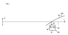
- FIG. 1 shows an outline of a head up display device according to the embodiment.
- a head up display device 100 according to the embodiment is installed in a dashboard of a vehicle 200.
- the head up display device 100 emits display light L representing a display image from an emitting part 101 to a front glass 201 of the vehicle 200.
- the display light L reflected by the front glass 201 reaches an eye 1 of an observer.
- the observer recognizes a virtual image (a virtual image projected on the front glass 201) V of the display image represented by the display light L reflected by the front glass 201.
- the observer recognizes a display image though the front glass 201 as if it is located distant and superimposed on a scene in front of the vehicle 200.
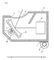
- Fig. 2 shows an outline of a cross section of the head up display device 100 in a horizontal direction of the vehicle 200 ( Fig. 1 ).
- Fig. 3 shows an electrical configuration of the head up display device 100.
- the head up display device 100 as shown in Fig. 2 , comprises a case 10, a display 20, a concave mirror 30, a first driving means 40, a second driving means 50, and a control means 60.
- the case 10 is a substantially box-shaped member made of a metal material such as aluminum.
- the case 10 is provided with various mounting shapes (not shown) inside, and able to retain the display 20 and the concave mirror 30 in a prescribed positional relationship in this embodiment.
- the inner surface of the case 10 is painted black, for example, to be less likely to occur stray light due to the outside and the display 20.
- a rack 11 is provided on the bottom surface of the case 10.
- the rack is provided with a plurality of teeth formed like a row in a longitudinal direction of the vehicle 200, and engaged with a gear 51 of the second driving means 50.
- the case 10 is provided movable in the longitudinal direction along with the rotational drive of the second driving means 50.
- an opening is provided as the emitting part 101 for emitting the display light L.
- the emitting part 101 is provided with a cover 12 made of transparent resin material to cover the opening.
- the display 20 comprises a TFT liquid crystal display element, for example, and an LED light source for transmilluminating the liquid crystal display element from the back side.
- the display 20 displays time and vehicle information such as vehicle traveling speed and f remaining fuel amount as a display image, and emits display light L representing the display image to the concave mirror 30.
- the concave mirror 30 is formed by depositing a reflective layer made of metal material such as aluminum on a resin substrate made of polycarbonate, for example.
- the concave mirror is arranged with the reflective surface faced upwardly inclined with respect to the display surface of the display 20, and magnifies and reflects the display light L emitted from the display 20 to the emitting part 101.
- the concave mirror 30 is provided with a gear 31 on the side opposite to the reflective surface (front side in Fig. 2 ).
- the gear 31 engages with a gear 41 of the first driving means 40.
- the concave mirror 30 is provided to be able to adjust an angle (rotation) in a longitudinal direction along with the rotational drive of the first driving means 40.
- the first driving means 40 comprises a stepping motor, for example, and is provided with the gear 41 in the rotation axis.
- the first driving means 40 is disposed within the case 10, and the gear 41 is engaged with the gear 31 of the concave mirror 30.
- an inclination angle in the longitudinal direction of the concave mirror 30 is adjusted.
- the second driving means 50 comprises a stepping motor, for example, and is provided with the gear 51 in the rotation axis.
- the second driving means 50 is disposed in a lower part of the case 10, and the gear 51 is engaged with the rack 11 of the case 10.
- the case 10 becomes movable in the longitudinal direction.
- the control means 60 controls the display 20, the first driving means 40, the second driving means 50, etc.
- the control means 60 sends an image signal to the display 20 to control the display 20 (to display a display image).
- the control means 60 comprises a CPU (Central Processing Unit) 61, a ROM (Read Only Memory) 62, a general-purpose memory 63, a video memory 64, an external interface 65, and the likes.
- the external interface 65 is connected to a CAN (Control Area Network) bus 67 for transmitting and receiving information about the display 20, the first driving means 40, the second driving means 50, and the vehicle 200.
- CAN Control Area Network
- the external interface 65 is connected to an input means 66, which accepts viewpoint position information (key input information and captured image information from an imaging means for imaging the eye 1 of the observer) for adjusting the inclination angle of the concave mirror 30 and the longitudinal position the case 10.
- viewpoint position information key input information and captured image information from an imaging means for imaging the eye 1 of the observer
- the front glass 201 is a glass having a predetermined curved surface (convex to the outside direction of the vehicle 200) ( Fig. 1 ).
- the display light L emitted from the display 20 is expanded by the concave mirror 30, and reflected back toward the emitting part 101.
- the display light L emitted from the emitting part 101 to the outside is projected on the front glass 201 of the vehicle 200.
- the display light L projected on the front glass 201 reaches the eye 1 of the observer.
- the observer recognizes a virtual image V of a display image represented by the display light L reflected by the front glass 201 as if it is superimposed on a scene in front of the vehicle 200.
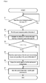
- the CPU 61 of the control means 60 inputs current viewpoint position information B (including at least height) of the observer.
- the viewpoint position information may be key input information made by the observer by operating a not-shown switch means based on an own viewpoint position, or may be captured image information input at predetermined time intervals from an image pickup means, which is provided for imaging a face of the observer (including at least the eye 1 of the observer).
- the CPU 61 moves to step S2 after inputting the current viewpoint position information B in step S1.
- the CPU 61 in step S2, reads past (previous) viewpoint position information A stored in the general-purpose memory 63, and in step S3, calculates a difference C between the past viewpoint position information A and the current viewpoint position information B.
- step S4 determines whether an absolute value of the difference C is greater than a predetermined threshold value x (
- a predetermined threshold value x
- the CPU 61 moves to step S5.
- the CPU 61 moves to step S7.
- the CPU 61 in step S5, reads, respectively the control values (correction values) of the first driving means 40 and the second driving means 50 corresponding to the current viewpoint position information B from the general-purpose memory 63. Then, the CPU 61, in step S6, outputs the control values to the first driving means 40 and the second driving means 50.
- the control values of the first driving means 40 and the second driving means 50 are set in a plural number in being associated with a plurality of values of viewpoint position information, for example, and stored in the general-purpose memory 63 as a data table.
- the first driving means 40 rotates based on the input control value, and adjusts the inclination angle of the concave mirror 30.
- the driving means 50 rotates based on the input control value, and moves the longitudinal position the case 10 (i.e., the longitudinal positions of the display 20 and the concave mirror 30).
- the CPU 61 in step S7, stores the current viewpoint position information B as the past viewpoint position information A in the general-purpose memory 63, and updates the past viewpoint position information A.
- the CPU 61 By repeatedly executing the above control until the power is turned off, the CPU 61 operates the first driving means 40 and the second driving means 50 according to the current viewpoint position information B of the observer, and moves the inclination angle of the concave mirror 30 and the longitudinal positions of the case 10. As a result, the CPU 61 can adjust the projection position of the display light L depending on the height of the observer's viewpoint position.
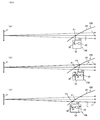
- Fig. 5 shows specific examples of a method of adjusting the projection position of the display light L.
- Fig. 5 (a) shows the case where the height of the eye 1 of the observer (viewpoint position) is located in a reference position (e.g., in the middle of upper and lower sides of an eye box).
- the display light L emitted from the emitting part 101 of the head up display device 100 is projected onto a predetermined projection point P1 on the front glass 201.
- the display light L reflects on the front glass 201, and reaches the eye 1 of the observer.
- the virtual image V of the display image is recognized at an arbitrary position in front (for example, 10 ⁇ 20 m forward) of the front glass 201.
- Fig. 5 (b) shows the case where the height of the eye 1 of the observer moves to a higher position with respect to the reference position.
- the CPU 61 executes the above control method, and controls the first driving means 40 and the second driving means 50 depending on the input of the current viewpoint position information B.
- the second driving means 50 rotates to move the case 10 rearward
- the first driving means 40 rotates to move the concave mirror 30 counterclockwise in Fig. 5 , namely, to incline the upper end of the concave mirror 30 forward, thereby adjusting the inclination angle of the concave mirror 30 more upward.
- the display light L emitted from the emitting part 101 is projected onto a projection point P2 located more upward the projection point P1 on the front glass 201.
- the display light L reflected by the front glass 201 reaches the eye 1 of the observer to be overlapped with the line of sight toward the arbitrary position in front of the front glass 201. Therefore, the observer can recognize the virtual image V even at a viewpoint higher than the reference position, without moving in a vertical direction from the position of the virtual image V at the reference position.
- Fig. 5 (c) shows the case where the height of the eye 1 of the observer moves to a lower position with respect to the reference position.
- the CPU 61 executes the above control method, and controls the first driving means 40 and the second driving means 50 depending on the input of the current viewpoint position information B.
- the second driving means 50 rotates to move the case 10 forward
- the first driving means 40 rotates to move the concave mirror 30 clockwise in Fig. 5 , namely, to incline the upper end of the concave mirror 30 rearward, thereby adjusting the inclination angle of the concave mirror 30 more downward.
- the display light emitted from the emitting part 101 is projected to a projection point P3 located more downward the projection point P1 on the front glass 201.
- the display light L reflected by the front glass 201 reaches the eye 1 of the observer to be overlapped with the line of sight toward the arbitrary position in front of the front glass 201 from the eye 1 of the observer. Therefore, the observer can recognize the virtual image V even at a viewpoint lower than the reference position, without moving in a vertical direction from the position of the virtual image V at the reference position.
- Fig. 6 shows the case where only the angle adjustment of the concave mirror 30 is performed depending on the height of the eye 1 of the observer (a conventional example).
- the first driving means 40 rotates to move the concave mirror 30 clockwise in Fig. 6 , namely, to incline the upper end of the concave mirror 30 rearward, thereby adjusting the inclination angle of the concave mirror 30 more downward.
- the display light L emitted from the emitting part 101 is projected onto a projection point P4 located more upward the projection point P1 at the reference position, and the display light L reflected by the front glass 201 reaches the eye 1 of the observer. Therefore, the observer can recognize the virtual image V at a high viewpoint position, but as the emission angle of the display light L from the front glass 201 is uniquely defined, the position of the virtual image V moves in a vertical direction.
- the first driving means 40 rotates to move the concave mirror 30 counterclockwise in Fig.
- the display light L is projected onto a projection point P5 located more downward the projection point P1 at the reference position, and the display light L reflected by the front glass 201 reaches the eye 1 of the observer. Therefore, the observer can recognize the virtual image V at a low viewpoint position, but the position of the virtual image V moves in a vertical direction.
- the head up display device 100 described in the above embodiment it is possible to adjust a projection position of display light depending on the height of a viewpoint of an observer, without moving a virtual image in a vertical direction. This is achieved by the following configurations.
- the head up display device 100 reflects the display light L representing a display image emitted from the display 20 by the concave mirror 30, and projects the display light to the front glass 201.
- the head up display device 100 comprises the case 10 that retains the display 20 and the concave mirror 30 in a prescribed positional relationship; a first driving means 40 that rotates the concave mirror 30; the second driving means 50 that moves the case 10 forward and rearward; and the control means 60 that operates the first and second driving means 40 and 50 according to a viewpoint position information of an observer, and adjusts a projection position of the display light L on the front glass 201 depending on a height of the observer's viewpoint.
- the case 10 moves only in a longitudinal direction, a space required for the movement is reduced compared with moving in an arc shape, and upsizing of the head up display device 100 can be suppressed. Further, it is unnecessary to use a semi-transparent mirror for adjusting a projection position of the display light L, and brightness of a virtual image is not decreased.
- Such head up display device 100 is provided with the general-purpose memory 63, which stores the correction values of the first and second driving means 40 and 50 corresponding to the viewpoint position information.
- the control means 60 operates the first and second driving means 40 and 50 based on the correction values.
- the viewpoint position information is captured image information output from an imaging means for imaging the eye 1 of an observer. Further, the viewpoint position information is switch input information by the observer.
- the control means 60 may change the operating states of the first and second driving means 40 and 50, that is, the correction parameters for correcting the distortion of the virtual image V in accordance with the projection position of the display light L.
- the correction parameters are used for previously displaying distortion of a display image in the direction reverse to the distortion on the front glass 201 in order to suppress the distortion of the virtual image V projected on the front glass 201.
- the general-purpose memory 63 stores a plurality of correction parameters in association with the control values of the first and second driving means 40 and 50.
- the CPU 61 of the control means 60 determines the correction parameters in accordance with the control values of the first and second driving means 40 and 50, which are determined by the control method described above, and outputs the correction parameters to the display 20.
- the distortion of the virtual image V can be suppressed.
- the head up display device 100 may be provided with a folding mirror within the case 10 for reflecting back the display light L emitted from the display 20 toward the concave mirror 30.
- an organic EL (Electroluminescence) display may be used as the display 20.
- a projection-type display may be used as the display 20.
- a combiner (projected member) that is projected by the display light L is not limited to the front glass 201 of the vehicle 200.
- a combiner that is projected by the display light L may be an exclusively provided combiner member.
- the present invention is suitable for a head up display device.
Landscapes
- Physics & Mathematics (AREA)
- General Physics & Mathematics (AREA)
- Optics & Photonics (AREA)
- Engineering & Computer Science (AREA)
- Health & Medical Sciences (AREA)
- General Health & Medical Sciences (AREA)
- Ophthalmology & Optometry (AREA)
- Human Computer Interaction (AREA)
- Multimedia (AREA)
- Theoretical Computer Science (AREA)
- Instrument Panels (AREA)
Abstract
Description
- The present invention relates to a head up display device.
- A display device for a vehicle called a head up display projects display light representing a display image emitted from a display onto a front glass or a dedicated combiner, and enables an observer (mainly, a driver) to recognize a virtual image of the display image superimposed on a scene viewed through a front glass or the like. On the other hand, a height of observer's viewpoint is not constant due to differences in physique and driving posture. Thus, it is necessary to adjust a projection point of display light in a vertical direction depending on the height of observer's viewpoint to enable the observer to recognize a virtual image even when the height of observer's viewpoint changes. As a conventional method of compensating for differences in the height of observer's viewpoint, a head up display disclosed in Patent Literatures 1 to 3 is known.
-
- Patent Literature 1: Japanese Unexamined Patent Application Publication No.
5-229366 - Patent Literature 2: Japanese Unexamined Patent Application Publication No.
7-329603 - Patent Literature 3: Japanese Unexamined Patent Application Publication No.
2010-179918 - The head up display disclosed in Patent Literature 1 is configured to vertically adjust a projection position of display light on a front glass or the like by enabling adjustment of inclination of a plane mirror for reflecting display light from a display toward a front glass or the like. However, in such a configuration, an incident position and an incident angle of display light to a front glass or the like are uniquely determined simultaneously with the adjustment of a display light projection position. Thus, a virtual image is vertically moved and deviated in superimposition with scenery.
- The head up display disclosed in Patent Literature 2 is configured to move both a display and a concave mirror (an optical path changing means) for directing display light to a front glass, along an arc centered on an intersection where a first temporary sight line of a first sight line and a second sight line intersects. The first temporary sight line of the first sight line is reflected and directed to a front glass. The first sight line is a sight line of a passenger viewing an image at a predetermined position outside a front glass from a high eye position. The second sight line is a sight line of a passenger viewing an image at a predetermined position outside a front glass from a low eye position. With such a configuration, it is possible to adjust a projection position of display light to a front glass without vertically moving a virtual image position. However, space is required in longitudinal and vertical directions for moving the display and the concave mirror along the arc, increasing the size of the head up display.
- The head up display disclosed in Patent Literature 3 is configured to arrange a display, a semitransparent reflection mirror, and optical elements for image expansion (including a second reflection mirror), in order at intervals along a longitudinal direction of a vehicle. With this configuration, display light is partially reflected by the second reflection mirror through the semitransparent reflection mirror, enlarged by the optical elements for image expansion, and reflected to the front glass by the semitransparent reflection mirror. The semitransparent reflection mirror is configured movable in a longitudinal direction and variable in an inclination angle, and the display and the second reflection mirror are not configured movable. With such a configuration, like in the Patent Literature 2, a projection position of display light onto a front glass is adjustable without vertically moving a virtual image position. However, there has been a problem that the semitransparent reflection mirror decreases brightness of a virtual image.
- The present invention has been made in view of the above. Accordingly, it is an object of the invention to provide a head up display device capable of adjusting a projection position of display light depending on a height of observer's viewpoint without moving a virtual image in a vertical direction.
- To achieve the above object, a head up display device according to the present invention reflects display light representing a display image emitted from a display by a concave mirror, and projects the display light to a combiner, the head up display device comprising:
- a case that retains the display and the concave mirror in a prescribed positional relationship;
- a first driving means that rotates the concave mirror;
- a second driving means that moves the case forward and rearward; and
- a control means that operates the first and second driving means according to information about a viewpoint position of an observer, and adjusts a projection position of the display light on the combiner depending on a height of observer's viewpoint.
- According to the present invention, the head up display device is possible to adjust a projection position of display light depending on a viewpoint height of an observer, without moving a virtual image in a vertical direction.
-
-
Fig. 1 is a schematic diagram showing an outline of a head up display device according to an embodiment of the present invention. -
Fig. 2 is a schematic cross-sectional view showing a configuration of a head up display device according to an embodiment of the invention. -
Fig. 3 is a block diagram showing an electrical configuration of a head up display device according to an embodiment of the invention. -
Fig. 4 is a flowchart showing a method of controlling first and second driving means according to an embodiment of the invention. -
Fig. 5 is a schematic diagram for explaining a method of adjusting a projection position of display light according to an embodiment of the invention. -
Fig. 6 is a schematic diagram for explaining a method of adjusting a projection position of display light according to a conventional example. - Hereinafter, an embodiment of the present invention will be described with reference to the drawings.
-
Fig. 1 shows an outline of a head up display device according to the embodiment. A head updisplay device 100 according to the embodiment is installed in a dashboard of avehicle 200. The head updisplay device 100 emits display light L representing a display image from an emittingpart 101 to afront glass 201 of thevehicle 200. The display light L reflected by thefront glass 201 reaches an eye 1 of an observer. The observer recognizes a virtual image (a virtual image projected on the front glass 201) V of the display image represented by the display light L reflected by thefront glass 201. The observer recognizes a display image though thefront glass 201 as if it is located distant and superimposed on a scene in front of thevehicle 200. -
Fig. 2 shows an outline of a cross section of the head updisplay device 100 in a horizontal direction of the vehicle 200 (Fig. 1 ).Fig. 3 shows an electrical configuration of the head updisplay device 100. - The head up
display device 100, as shown inFig. 2 , comprises acase 10, adisplay 20, aconcave mirror 30, a first driving means 40, a second driving means 50, and a control means 60. - The
case 10 is a substantially box-shaped member made of a metal material such as aluminum. Thecase 10 is provided with various mounting shapes (not shown) inside, and able to retain thedisplay 20 and theconcave mirror 30 in a prescribed positional relationship in this embodiment. The inner surface of thecase 10 is painted black, for example, to be less likely to occur stray light due to the outside and thedisplay 20. On the bottom surface of thecase 10, arack 11 is provided. The rack is provided with a plurality of teeth formed like a row in a longitudinal direction of thevehicle 200, and engaged with agear 51 of the second driving means 50. Thus, thecase 10 is provided movable in the longitudinal direction along with the rotational drive of the second driving means 50. On the top surface of thecase 10, an opening is provided as the emittingpart 101 for emitting the display light L. The emittingpart 101 is provided with acover 12 made of transparent resin material to cover the opening. - The
display 20 comprises a TFT liquid crystal display element, for example, and an LED light source for transmilluminating the liquid crystal display element from the back side. Thedisplay 20 displays time and vehicle information such as vehicle traveling speed and f remaining fuel amount as a display image, and emits display light L representing the display image to theconcave mirror 30. - The
concave mirror 30 is formed by depositing a reflective layer made of metal material such as aluminum on a resin substrate made of polycarbonate, for example. The concave mirror is arranged with the reflective surface faced upwardly inclined with respect to the display surface of thedisplay 20, and magnifies and reflects the display light L emitted from thedisplay 20 to the emittingpart 101. Theconcave mirror 30 is provided with agear 31 on the side opposite to the reflective surface (front side inFig. 2 ). Thegear 31 engages with agear 41 of the first driving means 40. Thus, theconcave mirror 30 is provided to be able to adjust an angle (rotation) in a longitudinal direction along with the rotational drive of the first driving means 40. - The first driving means 40 comprises a stepping motor, for example, and is provided with the
gear 41 in the rotation axis. The first driving means 40 is disposed within thecase 10, and thegear 41 is engaged with thegear 31 of theconcave mirror 30. Thus, along with the rotational drive of the first driving means 40, an inclination angle in the longitudinal direction of theconcave mirror 30 is adjusted. - The second driving means 50 comprises a stepping motor, for example, and is provided with the
gear 51 in the rotation axis. The second driving means 50 is disposed in a lower part of thecase 10, and thegear 51 is engaged with therack 11 of thecase 10. Thus, along with the rotational drive of the second driving means 50, thecase 10 becomes movable in the longitudinal direction. - The control means 60, as shown in
Fig. 3 , controls thedisplay 20, the first driving means 40, the second driving means 50, etc. For example, the control means 60 sends an image signal to thedisplay 20 to control the display 20 (to display a display image). The control means 60 comprises a CPU (Central Processing Unit) 61, a ROM (Read Only Memory) 62, a general-purpose memory 63, avideo memory 64, anexternal interface 65, and the likes. Theexternal interface 65 is connected to a CAN (Control Area Network)bus 67 for transmitting and receiving information about thedisplay 20, the first driving means 40, the second driving means 50, and thevehicle 200. Further, theexternal interface 65 is connected to an input means 66, which accepts viewpoint position information (key input information and captured image information from an imaging means for imaging the eye 1 of the observer) for adjusting the inclination angle of theconcave mirror 30 and the longitudinal position thecase 10. - In this embodiment, the
front glass 201 is a glass having a predetermined curved surface (convex to the outside direction of the vehicle 200) (Fig. 1 ). In this embodiment, the display light L emitted from thedisplay 20 is expanded by theconcave mirror 30, and reflected back toward the emittingpart 101. The display light L emitted from the emittingpart 101 to the outside is projected on thefront glass 201 of thevehicle 200. The display light L projected on thefront glass 201 reaches the eye 1 of the observer. The observer recognizes a virtual image V of a display image represented by the display light L reflected by thefront glass 201 as if it is superimposed on a scene in front of thevehicle 200. - Next, a method of controlling the first and second driving means provided in the head up
display device 100 will be described by usingFig. 4 . - The
CPU 61 of the control means 60, in step S1, inputs current viewpoint position information B (including at least height) of the observer. The viewpoint position information may be key input information made by the observer by operating a not-shown switch means based on an own viewpoint position, or may be captured image information input at predetermined time intervals from an image pickup means, which is provided for imaging a face of the observer (including at least the eye 1 of the observer). TheCPU 61 moves to step S2 after inputting the current viewpoint position information B in step S1. - Next, the
CPU 61, in step S2, reads past (previous) viewpoint position information A stored in the general-purpose memory 63, and in step S3, calculates a difference C between the past viewpoint position information A and the current viewpoint position information B. - Next, the
CPU 61, in step S4, determines whether an absolute value of the difference C is greater than a predetermined threshold value x (| C |> x). When the absolute value of the difference C is greater than the threshold value x (|C|> x) in step S4, or when a change in the observer's viewpoint position (a change in a vertical direction) is greater than a predetermined value, theCPU 61 moves to step S5. When the absolute value of the difference C is smaller than or equal to the threshold value x (|C | ≤ x) in step S4, or when a change in the observer's viewpoint position is smaller than or equal to a predetermined value, theCPU 61 moves to step S7. - The
CPU 61, in step S5, reads, respectively the control values (correction values) of the first driving means 40 and the second driving means 50 corresponding to the current viewpoint position information B from the general-purpose memory 63. Then, theCPU 61, in step S6, outputs the control values to the first driving means 40 and the second driving means 50. The control values of the first driving means 40 and the second driving means 50 are set in a plural number in being associated with a plurality of values of viewpoint position information, for example, and stored in the general-purpose memory 63 as a data table. The first driving means 40 rotates based on the input control value, and adjusts the inclination angle of theconcave mirror 30. The driving means 50 rotates based on the input control value, and moves the longitudinal position the case 10 (i.e., the longitudinal positions of thedisplay 20 and the concave mirror 30). - The
CPU 61, in step S7, stores the current viewpoint position information B as the past viewpoint position information A in the general-purpose memory 63, and updates the past viewpoint position information A. - By repeatedly executing the above control until the power is turned off, the
CPU 61 operates the first driving means 40 and the second driving means 50 according to the current viewpoint position information B of the observer, and moves the inclination angle of theconcave mirror 30 and the longitudinal positions of thecase 10. As a result, theCPU 61 can adjust the projection position of the display light L depending on the height of the observer's viewpoint position.Fig. 5 shows specific examples of a method of adjusting the projection position of the display light L. -
Fig. 5 (a) shows the case where the height of the eye 1 of the observer (viewpoint position) is located in a reference position (e.g., in the middle of upper and lower sides of an eye box). In this case, the display light L emitted from the emittingpart 101 of the head updisplay device 100 is projected onto a predetermined projection point P1 on thefront glass 201. The display light L reflects on thefront glass 201, and reaches the eye 1 of the observer. The virtual image V of the display image is recognized at an arbitrary position in front (for example, 10 ∼ 20 m forward) of thefront glass 201. -
Fig. 5 (b) shows the case where the height of the eye 1 of the observer moves to a higher position with respect to the reference position. At this time, theCPU 61 executes the above control method, and controls the first driving means 40 and the second driving means 50 depending on the input of the current viewpoint position information B. In this case, the second driving means 50 rotates to move thecase 10 rearward, and at the same time, the first driving means 40 rotates to move theconcave mirror 30 counterclockwise inFig. 5 , namely, to incline the upper end of theconcave mirror 30 forward, thereby adjusting the inclination angle of theconcave mirror 30 more upward. As a result, the display light L emitted from the emittingpart 101 is projected onto a projection point P2 located more upward the projection point P1 on thefront glass 201. The display light L reflected by thefront glass 201 reaches the eye 1 of the observer to be overlapped with the line of sight toward the arbitrary position in front of thefront glass 201. Therefore, the observer can recognize the virtual image V even at a viewpoint higher than the reference position, without moving in a vertical direction from the position of the virtual image V at the reference position. -
Fig. 5 (c) shows the case where the height of the eye 1 of the observer moves to a lower position with respect to the reference position. At this time, theCPU 61 executes the above control method, and controls the first driving means 40 and the second driving means 50 depending on the input of the current viewpoint position information B. In this case, the second driving means 50 rotates to move thecase 10 forward, and at the same time, the first driving means 40 rotates to move theconcave mirror 30 clockwise inFig. 5 , namely, to incline the upper end of theconcave mirror 30 rearward, thereby adjusting the inclination angle of theconcave mirror 30 more downward. As a result, the display light emitted from the emittingpart 101 is projected to a projection point P3 located more downward the projection point P1 on thefront glass 201. The display light L reflected by thefront glass 201 reaches the eye 1 of the observer to be overlapped with the line of sight toward the arbitrary position in front of thefront glass 201 from the eye 1 of the observer. Therefore, the observer can recognize the virtual image V even at a viewpoint lower than the reference position, without moving in a vertical direction from the position of the virtual image V at the reference position. - On the other hand,
Fig. 6 shows the case where only the angle adjustment of theconcave mirror 30 is performed depending on the height of the eye 1 of the observer (a conventional example). In this case, for recognizing the virtual image V when the position of the eye 1 of the observer is higher than the reference position, the first driving means 40 rotates to move theconcave mirror 30 clockwise inFig. 6 , namely, to incline the upper end of theconcave mirror 30 rearward, thereby adjusting the inclination angle of theconcave mirror 30 more downward. As a result, the display light L emitted from the emittingpart 101 is projected onto a projection point P4 located more upward the projection point P1 at the reference position, and the display light L reflected by thefront glass 201 reaches the eye 1 of the observer. Therefore, the observer can recognize the virtual image V at a high viewpoint position, but as the emission angle of the display light L from thefront glass 201 is uniquely defined, the position of the virtual image V moves in a vertical direction. To recognize the virtual image V when the positon of the eye 1 of the observer is lower than the reference position, the first driving means 40 rotates to move theconcave mirror 30 counterclockwise inFig. 6 , namely, to incline the upper end of theconcave mirror 30 forward, thereby adjusting the inclination angle of theconcave mirror 30 more downward. As a result, the display light L is projected onto a projection point P5 located more downward the projection point P1 at the reference position, and the display light L reflected by thefront glass 201 reaches the eye 1 of the observer. Therefore, the observer can recognize the virtual image V at a low viewpoint position, but the position of the virtual image V moves in a vertical direction. - According to the head up
display device 100 described in the above embodiment, it is possible to adjust a projection position of display light depending on the height of a viewpoint of an observer, without moving a virtual image in a vertical direction. This is achieved by the following configurations. - The head up
display device 100 reflects the display light L representing a display image emitted from thedisplay 20 by theconcave mirror 30, and projects the display light to thefront glass 201. The head updisplay device 100 comprises thecase 10 that retains thedisplay 20 and theconcave mirror 30 in a prescribed positional relationship; a first driving means 40 that rotates theconcave mirror 30; the second driving means 50 that moves thecase 10 forward and rearward; and the control means 60 that operates the first and second driving means 40 and 50 according to a viewpoint position information of an observer, and adjusts a projection position of the display light L on thefront glass 201 depending on a height of the observer's viewpoint. - Further, in such head up
display device 100, thecase 10 moves only in a longitudinal direction, a space required for the movement is reduced compared with moving in an arc shape, and upsizing of the head updisplay device 100 can be suppressed. Further, it is unnecessary to use a semi-transparent mirror for adjusting a projection position of the display light L, and brightness of a virtual image is not decreased. - Further, such head up
display device 100 is provided with the general-purpose memory 63, which stores the correction values of the first and second driving means 40 and 50 corresponding to the viewpoint position information. The control means 60 operates the first and second driving means 40 and 50 based on the correction values. - The viewpoint position information is captured image information output from an imaging means for imaging the eye 1 of an observer. Further, the viewpoint position information is switch input information by the observer.
- When the projection position of the display light L is different on the
front glass 201 having a curved surface, a distortion of the virtual image V may be different depending the projection position. In such a case, the control means 60 may change the operating states of the first and second driving means 40 and 50, that is, the correction parameters for correcting the distortion of the virtual image V in accordance with the projection position of the display light L. The correction parameters are used for previously displaying distortion of a display image in the direction reverse to the distortion on thefront glass 201 in order to suppress the distortion of the virtual image V projected on thefront glass 201. For example, the general-purpose memory 63 stores a plurality of correction parameters in association with the control values of the first and second driving means 40 and 50. TheCPU 61 of the control means 60 determines the correction parameters in accordance with the control values of the first and second driving means 40 and 50, which are determined by the control method described above, and outputs the correction parameters to thedisplay 20. Thus, even when the projection position of the display light L on thefront glass 201 is adjusted, the distortion of the virtual image V can be suppressed. - Further, the head up
display device 100 may be provided with a folding mirror within thecase 10 for reflecting back the display light L emitted from thedisplay 20 toward theconcave mirror 30. - Further, an organic EL (Electroluminescence) display, a projection-type display, and the like may be used as the
display 20. - A combiner (projected member) that is projected by the display light L is not limited to the
front glass 201 of thevehicle 200. A combiner that is projected by the display light L may be an exclusively provided combiner member. - In the above description, to facilitate the understanding of the present invention, a description of unimportant known technical matters is properly omitted.
- The present invention is suitable for a head up display device.
-
- 1
- Eye of observer
- 10
- Case
- 11
- Rack
- 20
- Display
- 30
- Concave mirror
- 31
- Gear
- 40
- First driving means
- 41
- Gear
- 50
- Second driving means
- 51
- Gear
- 60
- Control means
- 61
- CPU
- 62
- ROM
- 63
- General-purpose memory
- 64
- Video memory
- 65
- External interface
- 66
- Input means
- 67
- CAN bus
- 100
- Head up display device
- 101
- Emitting part
- 200
- Vehicle
- 201
- Front glass
- L
- Display light
- V
- Virtual image
Claims (5)
- A head up display device, which reflects display light representing a display image emitted from a display by a concave mirror, and projects the display light to a combiner, the head up display device comprising:a case that retains the display and the concave mirror in a prescribed positional relationship;a first driving means that rotates the concave mirror;a second driving means that moves the case forward and rearward; anda control means that operates the first and second driving means according to information about a viewpoint position of an observer, and adjusts a projection position of the display light on the combiner depending on a height of observer's viewpoint.
- The head up display device according to claim 1, comprising a memory for storing correction values of the first and second driving means corresponding to the viewpoint position information, wherein
the control means operates the first and second driving means based on the correction values. - The head up display device according to claim 1, wherein the viewpoint position information is captured image information output from an imaging means for imaging an eye of the observer.
- The head up display device according to claim 1, wherein the viewpoint position information is switch input information by the observer.
- The head up display device according to claim 1, wherein
the control means changes a correction parameter for correcting distortion of the virtual image in accordance with operating states of the first and second driving means.
Applications Claiming Priority (2)
| Application Number | Priority Date | Filing Date | Title |
|---|---|---|---|
| JP2013195574A JP6160398B2 (en) | 2013-09-20 | 2013-09-20 | Head-up display device |
| PCT/JP2014/074368 WO2015041203A1 (en) | 2013-09-20 | 2014-09-16 | Head up display device |
Publications (3)
| Publication Number | Publication Date |
|---|---|
| EP3048468A1 true EP3048468A1 (en) | 2016-07-27 |
| EP3048468A4 EP3048468A4 (en) | 2017-05-31 |
| EP3048468B1 EP3048468B1 (en) | 2022-02-16 |
Family
ID=52688853
Family Applications (1)
| Application Number | Title | Priority Date | Filing Date |
|---|---|---|---|
| EP14845171.9A Active EP3048468B1 (en) | 2013-09-20 | 2014-09-16 | Head up display device |
Country Status (4)
| Country | Link |
|---|---|
| US (1) | US9753289B2 (en) |
| EP (1) | EP3048468B1 (en) |
| JP (1) | JP6160398B2 (en) |
| WO (1) | WO2015041203A1 (en) |
Cited By (2)
| Publication number | Priority date | Publication date | Assignee | Title |
|---|---|---|---|---|
| WO2017186806A1 (en) * | 2016-04-29 | 2017-11-02 | Audi Ag | Heads-up display device with a holographically optical element for a motor vehicle |
| FR3072785A1 (en) * | 2017-10-24 | 2019-04-26 | Valeo Comfort And Driving Assistance | HIGH HEAD DISPLAY |
Families Citing this family (29)
| Publication number | Priority date | Publication date | Assignee | Title |
|---|---|---|---|---|
| JP6278769B2 (en) * | 2014-03-19 | 2018-02-14 | 矢崎総業株式会社 | Vehicle display device |
| CN105774679B (en) * | 2014-12-25 | 2019-01-29 | 比亚迪股份有限公司 | A kind of automobile, vehicle-mounted head-up-display system and its projected image height adjusting method |
| JP6474278B2 (en) * | 2015-02-27 | 2019-02-27 | 株式会社ソニー・インタラクティブエンタテインメント | Image generation system, image generation method, program, and information storage medium |
| JP6512016B2 (en) * | 2015-07-27 | 2019-05-15 | 日本精機株式会社 | Vehicle display device |
| DE102015010373B4 (en) * | 2015-08-07 | 2024-07-18 | Audi Ag | Method for adjusting a position of a virtual image of a head-up display of a motor vehicle, further head-up display and motor vehicle |
| CN105150935A (en) * | 2015-08-19 | 2015-12-16 | 京东方科技集团股份有限公司 | Head-up displayer, head-up display method and vehicle-mounted display device |
| DE102015116160B4 (en) | 2015-09-24 | 2022-10-13 | Denso Corporation | Head-up display with situation-based adjustment of the display of virtual image content |
| US20180356630A1 (en) * | 2015-11-25 | 2018-12-13 | Nippon Seiki Co., Ltd. | Head-up display |
| US10989929B2 (en) * | 2016-02-05 | 2021-04-27 | Maxell, Ltd. | Head-up display apparatus |
| US10871655B2 (en) * | 2016-02-12 | 2020-12-22 | Maxell, Ltd. | Image display apparatus for vehicle |
| CN105892647B (en) * | 2016-03-23 | 2018-09-25 | 京东方科技集团股份有限公司 | A kind of display screen method of adjustment, its device and display device |
| JP6828736B2 (en) * | 2016-03-28 | 2021-02-10 | 日本精機株式会社 | Vehicle display device |
| JP6874769B2 (en) * | 2016-08-10 | 2021-05-19 | 日本精機株式会社 | Vehicle display device |
| CN113296273B (en) | 2016-10-04 | 2023-03-21 | 麦克赛尔株式会社 | Optical system |
| CN107219889A (en) * | 2017-05-25 | 2017-09-29 | 京东方科技集团股份有限公司 | Eye-protecting display device and display screen method of adjustment |
| JP6841173B2 (en) * | 2017-06-30 | 2021-03-10 | 株式会社Jvcケンウッド | Virtual image display device |
| JP6971087B2 (en) * | 2017-08-25 | 2021-11-24 | 株式会社Subaru | Visual assistance device |
| JP7209197B2 (en) | 2018-03-13 | 2023-01-20 | パナソニックIpマネジメント株式会社 | Control device, vehicle, control method |
| WO2019224922A1 (en) * | 2018-05-22 | 2019-11-28 | 三菱電機株式会社 | Head-up display control device, head-up display system, and head-up display control method |
| EP3807702B1 (en) * | 2018-06-15 | 2023-09-13 | Continental Automotive Technologies GmbH | Apparatus for generating a virtual image with interference light suppression |
| JP2020016675A (en) | 2018-07-23 | 2020-01-30 | 株式会社Jvcケンウッド | Virtual image display device |
| CN112433379A (en) * | 2020-12-02 | 2021-03-02 | 未来汽车科技(深圳)有限公司 | Compensation method for virtual image height adjustment precision and optical machine using same |
| JP7578022B2 (en) * | 2021-02-24 | 2024-11-06 | 日本精機株式会社 | Display control device, display device, and image display control method |
| JP2022132089A (en) * | 2021-02-26 | 2022-09-07 | ダイハツ工業株式会社 | head-up display device |
| CN118235189A (en) * | 2021-11-15 | 2024-06-21 | 飞行安全国际公司 | System and method for adjusting the focus of an image displayed to a simulator user |
| JP7538165B2 (en) * | 2022-03-07 | 2024-08-21 | 矢崎総業株式会社 | Vehicle display device |
| JP2023158275A (en) * | 2022-04-18 | 2023-10-30 | 矢崎総業株式会社 | Vehicle display device |
| JP7827155B2 (en) * | 2022-08-10 | 2026-03-10 | 日産自動車株式会社 | Display control method and display control device |
| JPWO2024203229A1 (en) * | 2023-03-29 | 2024-10-03 |
Family Cites Families (19)
| Publication number | Priority date | Publication date | Assignee | Title |
|---|---|---|---|---|
| US3593259A (en) * | 1968-11-25 | 1971-07-13 | Singer General Precision | Alpha-gamma flight path display |
| JPS60183240A (en) * | 1984-03-02 | 1985-09-18 | Nissan Motor Co Ltd | Display unit for vehicle |
| JPH0332423Y2 (en) * | 1985-02-12 | 1991-07-10 | ||
| JPH0626433Y2 (en) * | 1987-02-23 | 1994-07-20 | 日産自動車株式会社 | Heads up display |
| JPH0328028A (en) * | 1989-06-27 | 1991-02-06 | Yazaki Corp | Reflective display device for vehicles |
| JPH0331033A (en) * | 1989-06-29 | 1991-02-08 | Mazda Motor Corp | Vehicle indicating device |
| JPH05229366A (en) | 1992-02-18 | 1993-09-07 | Kansei Corp | Head-up display device |
| JPH06115383A (en) * | 1992-10-06 | 1994-04-26 | Nippondenso Co Ltd | Display device for vehicle |
| JP2993304B2 (en) * | 1992-12-28 | 1999-12-20 | 日産自動車株式会社 | Display device for vehicles |
| JPH07329603A (en) * | 1994-06-13 | 1995-12-19 | Nippondenso Co Ltd | Display device for vehicle |
| US6580562B2 (en) * | 2000-07-24 | 2003-06-17 | Yazaki Corporation | On-vehicle display unit |
| DE102006035591B4 (en) * | 2006-07-26 | 2014-01-09 | Faurecia Innenraum Systeme Gmbh | A steering column assembly |
| JP2009163084A (en) * | 2008-01-09 | 2009-07-23 | Toshiba Corp | Display device and moving body |
| JP5447760B2 (en) * | 2008-02-20 | 2014-03-19 | 新電元工業株式会社 | Motor drive device |
| JP4686586B2 (en) | 2008-09-19 | 2011-05-25 | 株式会社東芝 | In-vehicle display device and display method |
| JP5145373B2 (en) | 2010-04-26 | 2013-02-13 | 矢崎総業株式会社 | Vehicle display device |
| JP6002376B2 (en) * | 2011-10-20 | 2016-10-05 | 矢崎総業株式会社 | Vehicle display device |
| JP6080704B2 (en) * | 2013-06-18 | 2017-02-15 | ミネベアミツミ株式会社 | Display device |
| WO2016208221A1 (en) * | 2015-06-24 | 2016-12-29 | パイオニア株式会社 | Display device |
-
2013
- 2013-09-20 JP JP2013195574A patent/JP6160398B2/en active Active
-
2014
- 2014-09-16 EP EP14845171.9A patent/EP3048468B1/en active Active
- 2014-09-16 WO PCT/JP2014/074368 patent/WO2015041203A1/en not_active Ceased
- 2014-09-16 US US14/915,168 patent/US9753289B2/en active Active
Non-Patent Citations (1)
| Title |
|---|
| See references of WO2015041203A1 * |
Cited By (3)
| Publication number | Priority date | Publication date | Assignee | Title |
|---|---|---|---|---|
| WO2017186806A1 (en) * | 2016-04-29 | 2017-11-02 | Audi Ag | Heads-up display device with a holographically optical element for a motor vehicle |
| FR3072785A1 (en) * | 2017-10-24 | 2019-04-26 | Valeo Comfort And Driving Assistance | HIGH HEAD DISPLAY |
| WO2019081603A1 (en) * | 2017-10-24 | 2019-05-02 | Valeo Comfort And Driving Assistance | Head-up display |
Also Published As
| Publication number | Publication date |
|---|---|
| EP3048468B1 (en) | 2022-02-16 |
| US9753289B2 (en) | 2017-09-05 |
| JP6160398B2 (en) | 2017-07-12 |
| WO2015041203A1 (en) | 2015-03-26 |
| JP2015060180A (en) | 2015-03-30 |
| EP3048468A4 (en) | 2017-05-31 |
| US20160209663A1 (en) | 2016-07-21 |
Similar Documents
| Publication | Publication Date | Title |
|---|---|---|
| US9753289B2 (en) | Head up display device | |
| CN112904558B (en) | HUD Calibration | |
| CN108422933B (en) | Head-up display device for realizing individually controllable multiple display fields and display control method thereof | |
| JP6278769B2 (en) | Vehicle display device | |
| US10302940B2 (en) | Head-up display | |
| EP3557307B1 (en) | Image display device | |
| CN104166238B (en) | Apparatus and method for projecting image information into the field of view of an occupant of a vehicle | |
| JP4847627B1 (en) | Display device | |
| EP2784581A1 (en) | Projector and head-up display device and a light dimming control method | |
| EP3125017A1 (en) | Image display apparatus | |
| WO2016190135A1 (en) | Vehicular display system | |
| US12055713B2 (en) | Head-up display system | |
| JP6455230B2 (en) | Head-up display system | |
| JP2017024444A (en) | Image forming apparatus and image forming method | |
| US20200124846A1 (en) | Display device | |
| JP2007191116A (en) | Vehicle display device | |
| JP2016185768A (en) | Vehicle display system | |
| JP6481445B2 (en) | Head-up display | |
| CN110385990B (en) | Vehicle head-up display device and control method thereof | |
| JP6441026B2 (en) | Head-up display device for vehicle | |
| JP7282573B2 (en) | vehicle display | |
| JP6644105B2 (en) | HEAD-UP DISPLAY DEVICE FOR VEHICLE AND CONTROL METHOD THEREOF | |
| JP2018031861A (en) | Display device for vehicle | |
| JP2023092264A (en) | virtual image display |
Legal Events
| Date | Code | Title | Description |
|---|---|---|---|
| PUAI | Public reference made under article 153(3) epc to a published international application that has entered the european phase |
Free format text: ORIGINAL CODE: 0009012 |
|
| 17P | Request for examination filed |
Effective date: 20160324 |
|
| AK | Designated contracting states |
Kind code of ref document: A1 Designated state(s): AL AT BE BG CH CY CZ DE DK EE ES FI FR GB GR HR HU IE IS IT LI LT LU LV MC MK MT NL NO PL PT RO RS SE SI SK SM TR |
|
| AX | Request for extension of the european patent |
Extension state: BA ME |
|
| DAX | Request for extension of the european patent (deleted) | ||
| A4 | Supplementary search report drawn up and despatched |
Effective date: 20170503 |
|
| RIC1 | Information provided on ipc code assigned before grant |
Ipc: G02B 27/01 20060101AFI20170425BHEP Ipc: B60K 35/00 20060101ALI20170425BHEP |
|
| STAA | Information on the status of an ep patent application or granted ep patent |
Free format text: STATUS: EXAMINATION IS IN PROGRESS |
|
| 17Q | First examination report despatched |
Effective date: 20200730 |
|
| GRAP | Despatch of communication of intention to grant a patent |
Free format text: ORIGINAL CODE: EPIDOSNIGR1 |
|
| STAA | Information on the status of an ep patent application or granted ep patent |
Free format text: STATUS: GRANT OF PATENT IS INTENDED |
|
| INTG | Intention to grant announced |
Effective date: 20211025 |
|
| GRAS | Grant fee paid |
Free format text: ORIGINAL CODE: EPIDOSNIGR3 |
|
| GRAA | (expected) grant |
Free format text: ORIGINAL CODE: 0009210 |
|
| STAA | Information on the status of an ep patent application or granted ep patent |
Free format text: STATUS: THE PATENT HAS BEEN GRANTED |
|
| AK | Designated contracting states |
Kind code of ref document: B1 Designated state(s): AL AT BE BG CH CY CZ DE DK EE ES FI FR GB GR HR HU IE IS IT LI LT LU LV MC MK MT NL NO PL PT RO RS SE SI SK SM TR |
|
| REG | Reference to a national code |
Ref country code: GB Ref legal event code: FG4D |
|
| REG | Reference to a national code |
Ref country code: CH Ref legal event code: EP |
|
| REG | Reference to a national code |
Ref country code: DE Ref legal event code: R096 Ref document number: 602014082541 Country of ref document: DE |
|
| REG | Reference to a national code |
Ref country code: AT Ref legal event code: REF Ref document number: 1469249 Country of ref document: AT Kind code of ref document: T Effective date: 20220315 |
|
| REG | Reference to a national code |
Ref country code: IE Ref legal event code: FG4D |
|
| REG | Reference to a national code |
Ref country code: LT Ref legal event code: MG9D |
|
| REG | Reference to a national code |
Ref country code: NL Ref legal event code: MP Effective date: 20220216 |
|
| REG | Reference to a national code |
Ref country code: AT Ref legal event code: MK05 Ref document number: 1469249 Country of ref document: AT Kind code of ref document: T Effective date: 20220216 |
|
| PG25 | Lapsed in a contracting state [announced via postgrant information from national office to epo] |
Ref country code: SE Free format text: LAPSE BECAUSE OF FAILURE TO SUBMIT A TRANSLATION OF THE DESCRIPTION OR TO PAY THE FEE WITHIN THE PRESCRIBED TIME-LIMIT Effective date: 20220216 Ref country code: RS Free format text: LAPSE BECAUSE OF FAILURE TO SUBMIT A TRANSLATION OF THE DESCRIPTION OR TO PAY THE FEE WITHIN THE PRESCRIBED TIME-LIMIT Effective date: 20220216 Ref country code: PT Free format text: LAPSE BECAUSE OF FAILURE TO SUBMIT A TRANSLATION OF THE DESCRIPTION OR TO PAY THE FEE WITHIN THE PRESCRIBED TIME-LIMIT Effective date: 20220616 Ref country code: NO Free format text: LAPSE BECAUSE OF FAILURE TO SUBMIT A TRANSLATION OF THE DESCRIPTION OR TO PAY THE FEE WITHIN THE PRESCRIBED TIME-LIMIT Effective date: 20220516 Ref country code: NL Free format text: LAPSE BECAUSE OF FAILURE TO SUBMIT A TRANSLATION OF THE DESCRIPTION OR TO PAY THE FEE WITHIN THE PRESCRIBED TIME-LIMIT Effective date: 20220216 Ref country code: LT Free format text: LAPSE BECAUSE OF FAILURE TO SUBMIT A TRANSLATION OF THE DESCRIPTION OR TO PAY THE FEE WITHIN THE PRESCRIBED TIME-LIMIT Effective date: 20220216 Ref country code: HR Free format text: LAPSE BECAUSE OF FAILURE TO SUBMIT A TRANSLATION OF THE DESCRIPTION OR TO PAY THE FEE WITHIN THE PRESCRIBED TIME-LIMIT Effective date: 20220216 Ref country code: ES Free format text: LAPSE BECAUSE OF FAILURE TO SUBMIT A TRANSLATION OF THE DESCRIPTION OR TO PAY THE FEE WITHIN THE PRESCRIBED TIME-LIMIT Effective date: 20220216 Ref country code: BG Free format text: LAPSE BECAUSE OF FAILURE TO SUBMIT A TRANSLATION OF THE DESCRIPTION OR TO PAY THE FEE WITHIN THE PRESCRIBED TIME-LIMIT Effective date: 20220516 |
|
| PG25 | Lapsed in a contracting state [announced via postgrant information from national office to epo] |
Ref country code: PL Free format text: LAPSE BECAUSE OF FAILURE TO SUBMIT A TRANSLATION OF THE DESCRIPTION OR TO PAY THE FEE WITHIN THE PRESCRIBED TIME-LIMIT Effective date: 20220216 Ref country code: LV Free format text: LAPSE BECAUSE OF FAILURE TO SUBMIT A TRANSLATION OF THE DESCRIPTION OR TO PAY THE FEE WITHIN THE PRESCRIBED TIME-LIMIT Effective date: 20220216 Ref country code: GR Free format text: LAPSE BECAUSE OF FAILURE TO SUBMIT A TRANSLATION OF THE DESCRIPTION OR TO PAY THE FEE WITHIN THE PRESCRIBED TIME-LIMIT Effective date: 20220517 Ref country code: FI Free format text: LAPSE BECAUSE OF FAILURE TO SUBMIT A TRANSLATION OF THE DESCRIPTION OR TO PAY THE FEE WITHIN THE PRESCRIBED TIME-LIMIT Effective date: 20220216 Ref country code: AT Free format text: LAPSE BECAUSE OF FAILURE TO SUBMIT A TRANSLATION OF THE DESCRIPTION OR TO PAY THE FEE WITHIN THE PRESCRIBED TIME-LIMIT Effective date: 20220216 |
|
| PG25 | Lapsed in a contracting state [announced via postgrant information from national office to epo] |
Ref country code: IS Free format text: LAPSE BECAUSE OF FAILURE TO SUBMIT A TRANSLATION OF THE DESCRIPTION OR TO PAY THE FEE WITHIN THE PRESCRIBED TIME-LIMIT Effective date: 20220616 |
|
| PG25 | Lapsed in a contracting state [announced via postgrant information from national office to epo] |
Ref country code: SM Free format text: LAPSE BECAUSE OF FAILURE TO SUBMIT A TRANSLATION OF THE DESCRIPTION OR TO PAY THE FEE WITHIN THE PRESCRIBED TIME-LIMIT Effective date: 20220216 Ref country code: SK Free format text: LAPSE BECAUSE OF FAILURE TO SUBMIT A TRANSLATION OF THE DESCRIPTION OR TO PAY THE FEE WITHIN THE PRESCRIBED TIME-LIMIT Effective date: 20220216 Ref country code: RO Free format text: LAPSE BECAUSE OF FAILURE TO SUBMIT A TRANSLATION OF THE DESCRIPTION OR TO PAY THE FEE WITHIN THE PRESCRIBED TIME-LIMIT Effective date: 20220216 Ref country code: EE Free format text: LAPSE BECAUSE OF FAILURE TO SUBMIT A TRANSLATION OF THE DESCRIPTION OR TO PAY THE FEE WITHIN THE PRESCRIBED TIME-LIMIT Effective date: 20220216 Ref country code: DK Free format text: LAPSE BECAUSE OF FAILURE TO SUBMIT A TRANSLATION OF THE DESCRIPTION OR TO PAY THE FEE WITHIN THE PRESCRIBED TIME-LIMIT Effective date: 20220216 Ref country code: CZ Free format text: LAPSE BECAUSE OF FAILURE TO SUBMIT A TRANSLATION OF THE DESCRIPTION OR TO PAY THE FEE WITHIN THE PRESCRIBED TIME-LIMIT Effective date: 20220216 |
|
| REG | Reference to a national code |
Ref country code: DE Ref legal event code: R097 Ref document number: 602014082541 Country of ref document: DE |
|
| PG25 | Lapsed in a contracting state [announced via postgrant information from national office to epo] |
Ref country code: AL Free format text: LAPSE BECAUSE OF FAILURE TO SUBMIT A TRANSLATION OF THE DESCRIPTION OR TO PAY THE FEE WITHIN THE PRESCRIBED TIME-LIMIT Effective date: 20220216 |
|
| PLBE | No opposition filed within time limit |
Free format text: ORIGINAL CODE: 0009261 |
|
| STAA | Information on the status of an ep patent application or granted ep patent |
Free format text: STATUS: NO OPPOSITION FILED WITHIN TIME LIMIT |
|
| 26N | No opposition filed |
Effective date: 20221117 |
|
| PG25 | Lapsed in a contracting state [announced via postgrant information from national office to epo] |
Ref country code: SI Free format text: LAPSE BECAUSE OF FAILURE TO SUBMIT A TRANSLATION OF THE DESCRIPTION OR TO PAY THE FEE WITHIN THE PRESCRIBED TIME-LIMIT Effective date: 20220216 |
|
| PG25 | Lapsed in a contracting state [announced via postgrant information from national office to epo] |
Ref country code: MC Free format text: LAPSE BECAUSE OF FAILURE TO SUBMIT A TRANSLATION OF THE DESCRIPTION OR TO PAY THE FEE WITHIN THE PRESCRIBED TIME-LIMIT Effective date: 20220216 |
|
| REG | Reference to a national code |
Ref country code: CH Ref legal event code: PL |
|
| GBPC | Gb: european patent ceased through non-payment of renewal fee |
Effective date: 20220916 |
|
| REG | Reference to a national code |
Ref country code: BE Ref legal event code: MM Effective date: 20220930 |
|
| PG25 | Lapsed in a contracting state [announced via postgrant information from national office to epo] |
Ref country code: LU Free format text: LAPSE BECAUSE OF NON-PAYMENT OF DUE FEES Effective date: 20220916 |
|
| PG25 | Lapsed in a contracting state [announced via postgrant information from national office to epo] |
Ref country code: LI Free format text: LAPSE BECAUSE OF NON-PAYMENT OF DUE FEES Effective date: 20220930 Ref country code: IT Free format text: LAPSE BECAUSE OF FAILURE TO SUBMIT A TRANSLATION OF THE DESCRIPTION OR TO PAY THE FEE WITHIN THE PRESCRIBED TIME-LIMIT Effective date: 20220216 Ref country code: IE Free format text: LAPSE BECAUSE OF NON-PAYMENT OF DUE FEES Effective date: 20220916 Ref country code: FR Free format text: LAPSE BECAUSE OF NON-PAYMENT OF DUE FEES Effective date: 20220930 Ref country code: CH Free format text: LAPSE BECAUSE OF NON-PAYMENT OF DUE FEES Effective date: 20220930 |
|
| PG25 | Lapsed in a contracting state [announced via postgrant information from national office to epo] |
Ref country code: BE Free format text: LAPSE BECAUSE OF NON-PAYMENT OF DUE FEES Effective date: 20220930 |
|
| PG25 | Lapsed in a contracting state [announced via postgrant information from national office to epo] |
Ref country code: GB Free format text: LAPSE BECAUSE OF NON-PAYMENT OF DUE FEES Effective date: 20220916 |
|
| PG25 | Lapsed in a contracting state [announced via postgrant information from national office to epo] |
Ref country code: HU Free format text: LAPSE BECAUSE OF FAILURE TO SUBMIT A TRANSLATION OF THE DESCRIPTION OR TO PAY THE FEE WITHIN THE PRESCRIBED TIME-LIMIT; INVALID AB INITIO Effective date: 20140916 |
|
| PG25 | Lapsed in a contracting state [announced via postgrant information from national office to epo] |
Ref country code: CY Free format text: LAPSE BECAUSE OF FAILURE TO SUBMIT A TRANSLATION OF THE DESCRIPTION OR TO PAY THE FEE WITHIN THE PRESCRIBED TIME-LIMIT Effective date: 20220216 |
|
| PG25 | Lapsed in a contracting state [announced via postgrant information from national office to epo] |
Ref country code: MK Free format text: LAPSE BECAUSE OF FAILURE TO SUBMIT A TRANSLATION OF THE DESCRIPTION OR TO PAY THE FEE WITHIN THE PRESCRIBED TIME-LIMIT Effective date: 20220216 |
|
| PG25 | Lapsed in a contracting state [announced via postgrant information from national office to epo] |
Ref country code: MT Free format text: LAPSE BECAUSE OF FAILURE TO SUBMIT A TRANSLATION OF THE DESCRIPTION OR TO PAY THE FEE WITHIN THE PRESCRIBED TIME-LIMIT Effective date: 20220216 |
|
| PGFP | Annual fee paid to national office [announced via postgrant information from national office to epo] |
Ref country code: DE Payment date: 20250730 Year of fee payment: 12 |
|
| PG25 | Lapsed in a contracting state [announced via postgrant information from national office to epo] |
Ref country code: TR Free format text: LAPSE BECAUSE OF FAILURE TO SUBMIT A TRANSLATION OF THE DESCRIPTION OR TO PAY THE FEE WITHIN THE PRESCRIBED TIME-LIMIT Effective date: 20220216 |