EP3048261B1 - Statische turbinendichtung mit hilfsdichtung - Google Patents
Statische turbinendichtung mit hilfsdichtung Download PDFInfo
- Publication number
- EP3048261B1 EP3048261B1 EP16152189.3A EP16152189A EP3048261B1 EP 3048261 B1 EP3048261 B1 EP 3048261B1 EP 16152189 A EP16152189 A EP 16152189A EP 3048261 B1 EP3048261 B1 EP 3048261B1
- Authority
- EP
- European Patent Office
- Prior art keywords
- seal
- contact surface
- turbine
- sealing arrangement
- compartment
- Prior art date
- Legal status (The legal status is an assumption and is not a legal conclusion. Google has not performed a legal analysis and makes no representation as to the accuracy of the status listed.)
- Active
Links
Images


Classifications
-
- F—MECHANICAL ENGINEERING; LIGHTING; HEATING; WEAPONS; BLASTING
- F02—COMBUSTION ENGINES; HOT-GAS OR COMBUSTION-PRODUCT ENGINE PLANTS
- F02C—GAS-TURBINE PLANTS; AIR INTAKES FOR JET-PROPULSION PLANTS; CONTROLLING FUEL SUPPLY IN AIR-BREATHING JET-PROPULSION PLANTS
- F02C7/00—Features, components parts, details or accessories, not provided for in, or of interest apart form groups F02C1/00 - F02C6/00; Air intakes for jet-propulsion plants
- F02C7/08—Heating air supply before combustion, e.g. by exhaust gases
-
- F—MECHANICAL ENGINEERING; LIGHTING; HEATING; WEAPONS; BLASTING
- F01—MACHINES OR ENGINES IN GENERAL; ENGINE PLANTS IN GENERAL; STEAM ENGINES
- F01D—NON-POSITIVE DISPLACEMENT MACHINES OR ENGINES, e.g. STEAM TURBINES
- F01D11/00—Preventing or minimising internal leakage of working-fluid, e.g. between stages
- F01D11/003—Preventing or minimising internal leakage of working-fluid, e.g. between stages by packing rings; Mechanical seals
-
- F—MECHANICAL ENGINEERING; LIGHTING; HEATING; WEAPONS; BLASTING
- F01—MACHINES OR ENGINES IN GENERAL; ENGINE PLANTS IN GENERAL; STEAM ENGINES
- F01D—NON-POSITIVE DISPLACEMENT MACHINES OR ENGINES, e.g. STEAM TURBINES
- F01D25/00—Component parts, details, or accessories, not provided for in, or of interest apart from, other groups
- F01D25/08—Cooling; Heating; Heat-insulation
- F01D25/12—Cooling
-
- F—MECHANICAL ENGINEERING; LIGHTING; HEATING; WEAPONS; BLASTING
- F01—MACHINES OR ENGINES IN GENERAL; ENGINE PLANTS IN GENERAL; STEAM ENGINES
- F01D—NON-POSITIVE DISPLACEMENT MACHINES OR ENGINES, e.g. STEAM TURBINES
- F01D25/00—Component parts, details, or accessories, not provided for in, or of interest apart from, other groups
- F01D25/16—Arrangement of bearings; Supporting or mounting bearings in casings
-
- F—MECHANICAL ENGINEERING; LIGHTING; HEATING; WEAPONS; BLASTING
- F16—ENGINEERING ELEMENTS AND UNITS; GENERAL MEASURES FOR PRODUCING AND MAINTAINING EFFECTIVE FUNCTIONING OF MACHINES OR INSTALLATIONS; THERMAL INSULATION IN GENERAL
- F16J—PISTONS; CYLINDERS; SEALINGS
- F16J15/00—Sealings
- F16J15/02—Sealings between relatively-stationary surfaces
- F16J15/06—Sealings between relatively-stationary surfaces with solid packing compressed between sealing surfaces
- F16J15/08—Sealings between relatively-stationary surfaces with solid packing compressed between sealing surfaces with exclusively metal packing
- F16J15/0887—Sealings between relatively-stationary surfaces with solid packing compressed between sealing surfaces with exclusively metal packing the sealing effect being obtained by elastic deformation of the packing
-
- F—MECHANICAL ENGINEERING; LIGHTING; HEATING; WEAPONS; BLASTING
- F02—COMBUSTION ENGINES; HOT-GAS OR COMBUSTION-PRODUCT ENGINE PLANTS
- F02C—GAS-TURBINE PLANTS; AIR INTAKES FOR JET-PROPULSION PLANTS; CONTROLLING FUEL SUPPLY IN AIR-BREATHING JET-PROPULSION PLANTS
- F02C7/00—Features, components parts, details or accessories, not provided for in, or of interest apart form groups F02C1/00 - F02C6/00; Air intakes for jet-propulsion plants
- F02C7/28—Arrangement of seals
-
- F—MECHANICAL ENGINEERING; LIGHTING; HEATING; WEAPONS; BLASTING
- F05—INDEXING SCHEMES RELATING TO ENGINES OR PUMPS IN VARIOUS SUBCLASSES OF CLASSES F01-F04
- F05D—INDEXING SCHEME FOR ASPECTS RELATING TO NON-POSITIVE-DISPLACEMENT MACHINES OR ENGINES, GAS-TURBINES OR JET-PROPULSION PLANTS
- F05D2240/00—Components
- F05D2240/55—Seals
- F05D2240/58—Piston ring seals
- F05D2240/581—Double or plural piston ring arrangements, i.e. two or more piston rings
-
- F—MECHANICAL ENGINEERING; LIGHTING; HEATING; WEAPONS; BLASTING
- F05—INDEXING SCHEMES RELATING TO ENGINES OR PUMPS IN VARIOUS SUBCLASSES OF CLASSES F01-F04
- F05D—INDEXING SCHEME FOR ASPECTS RELATING TO NON-POSITIVE-DISPLACEMENT MACHINES OR ENGINES, GAS-TURBINES OR JET-PROPULSION PLANTS
- F05D2250/00—Geometry
- F05D2250/70—Shape
- F05D2250/75—Shape given by its similarity to a letter, e.g. T-shaped
-
- Y—GENERAL TAGGING OF NEW TECHNOLOGICAL DEVELOPMENTS; GENERAL TAGGING OF CROSS-SECTIONAL TECHNOLOGIES SPANNING OVER SEVERAL SECTIONS OF THE IPC; TECHNICAL SUBJECTS COVERED BY FORMER USPC CROSS-REFERENCE ART COLLECTIONS [XRACs] AND DIGESTS
- Y02—TECHNOLOGIES OR APPLICATIONS FOR MITIGATION OR ADAPTATION AGAINST CLIMATE CHANGE
- Y02T—CLIMATE CHANGE MITIGATION TECHNOLOGIES RELATED TO TRANSPORTATION
- Y02T50/00—Aeronautics or air transport
- Y02T50/60—Efficient propulsion technologies, e.g. for aircraft
Definitions
- the present invention relates generally to gas turbine engines, and more particularly to a seal arrangement of a gas turbine engine.
- a gas turbine engine typically includes a high pressure spool, a combustion system and a low pressure spool disposed within an engine case to form a generally axial, serial flow path about the engine centerline.
- the high pressure spool includes a high pressure turbine, a high pressure shaft extending axially forward from the high pressure turbine, and a high pressure compressor connected to a forward end of the high pressure shaft.
- the low pressure spool includes a low pressure turbine, which is disposed downstream of the high pressure turbine, a low pressure shaft, which typically extends coaxially through the high pressure shaft, and a low pressure compressor connected to a forward end of the low pressure shaft, forward of the high pressure compressor.
- the combustion system is disposed between the high pressure compressor and the high pressure turbine and receives compressed air from the compressors and fuel provided by a fuel injection system.
- a combustion process is carried out within the combustion system to produce high energy gases to produce thrust and turn the high and low pressure turbines, which drive the compressors to sustain the combustion process.
- Both the high and low pressure spools include alternating cascades of stators and rotors in order to work on the primary fluid in the flow path. Because the stators are stationary but the rotors rotate, bearings are necessary to permit the relative motion. Bearings can be situated in bearing compartments that provide oil to the moving parts for lubrication.
- the combustion system heats the primary fluid in the flow path to very high temperatures, so both the high and low pressure turbines utilize cooling air from the high and/or low pressure compressors.
- This cooling air can be fed into a bearing compartment in order to cool and purge the bearing compartment of any stray oil that has leaked out. Because the boundaries of the bearing compartment can be formed by several components, seal arrangements are utilized between the components to control fluid flow.
- EP 2 479 406 related to a bearing system.
- a sealing arrangement has a turbine static structure having a seal ring with a radially inward-facing groove with an annular first contact surface and an annular second contact surface on the seal ring that is distal and radially inward from the first contact surface.
- the sealing arrangement comprises further a bearing compartment structure that is surrounded by the turbine static structure having a heat shield, the heat shield comprising an axial portion with a cylindrical third contact surface and a radial portion connected to the axial portion with an annular fourth contact surface that is distal and radially inward from the third contact surface; a cavity between the turbine static structure and the bearing compartment structure; a first seal positioned between the turbine static structure and the bearing compartment structure, the first seal being in contact with the first contact surface and the third contact surface; a second seal positioned between the turbine static structure and the bearing compartment structure, the second seal being in contact with the second contact surface and the fourth contact surface; and a fastener compartment between the seal ring and the bearing compartment structure and bordered by the first seal and the second seal.
- FIG. 1 a cross section of gas turbine engine 10 is shown.
- FIG. 1 depicts a gas turbine engine typically used for aircraft propulsion, the invention is readily applicable to gas turbine generators and other similar systems incorporating rotor-supported, shaft-driven turbines. Shown in FIG.
- gas turbine engine 10 gas turbine engine 10, fan 12, low pressure compressor (LPC) 14, high pressure compressor (HPC) 16, combustor section 18, high pressure turbine (HPT) 20, low pressure turbine (LPT) 22, fan case 24, LPC case 26, HPC case 28, HPT case 30, LPT case 32, low pressure shaft 34, high pressure shaft 36, exit guide vanes 38, injectors 40, HPT blades 41, LPT blades 42, support rotor 44, vane airfoil sections 46, case section 48, supply line 50, rod 52, mid-turbine frame 54, bearing compartment 56, inlet air A, primary air A P , secondary air A S (also known as bypass air), and longitudinal engine centerline axis C L .
- gas turbine engine 10 comprises a dual-spool turbofan engine in which the advantages of the present invention are particularly well illustrated.
- Gas turbine engine 10 of which the operational principles are well known in the art, comprises fan 12, low pressure compressor (LPC) 14, high pressure compressor (HPC) 16, combustor section 18, high pressure turbine (HPT) 20, and low pressure turbine (LPT) 22, which are each concentrically disposed around longitudinal engine centerline axis C L .
- Fan 12 is enclosed at its outer diameter within fan case 24.
- the other engine components are correspondingly enclosed at their outer diameters within various engine casings, including LPC case 26, HPC case 28, HPT case 30 and LPT case 32.
- Fan 12 and LPC 14 are connected to LPT 22 through low pressure shaft 34, and together with fan 12, LPC 14, LPT 22, and low pressure shaft 34 comprise the low pressure spool.
- HPC 16 is connected to HPT 20 through high pressure shaft 36, and together HPC 16, HPT 20, and high pressure shaft 36 comprise the high pressure spool.
- inlet air A enters engine 10 where it is divided into streams of primary air A P and secondary air A S after passing through fan 12.
- Fan 12 is rotated by low pressure turbine 22 through low pressure shaft 34 (either directly as shown or through a gearbox, not shown) to accelerate secondary air A S (also known as bypass air) through exit guide vanes 38, thereby producing a major portion of the thrust output of engine 10.
- Primary air A P also known as gas path air
- LPC 14 and HPC 16 work together to incrementally step up the pressure of primary air A P .
- HPC 16 is rotated by HPT 20 through low pressure shaft 34 to provide compressed air to combustor section 18.
- the compressed air is delivered to combustors 18A-18B, along with fuel through injectors 40, such that a combustion process can be carried out to produce the high energy gases necessary to turn high pressure turbine 20 and low pressure turbine 22.
- Primary air A P continues through gas turbine engine 10 whereby it is typically passed through an exhaust nozzle to further produce thrust.
- a portion of primary air A P can be bled off from at least one of LPC 14, HPC 16, and in between LPC 14 and HPC 16 through supply line 50.
- This air is used for cooling components of HPT 20 and LPT 22, so the air travels through supply line 50 into rod 52.
- Rod 52 is hollow and is a component within mid-turbine frame 54.
- Mid-turbine frame 54 is a turbine static structure that extends across the flow path of primary air A P .
- the cooling air is directed through rod 52 to LPT 22 and towards bearing compartment 56.
- bearing compartment 56 contains the number four bearing (i.e. the fourth bearing in from the front of gas turbine engine 10). Therefore, bearing compartment 56 is positioned in between HPT 20 and LPT 22 along longitudinal engine centerline axis C L such that bearing compartment 56 is proximate HPT 20 and LPT 22.
- gas turbine engine 10 as shown in FIG. 1 allow for a portion of primary air A P upstream of combustor section 18 to be transported downstream of combustor section 18. Because this air is relatively cool (having not gone through combustor section 18), the air can be used to cool components such as bearing compartment 56. This is advantageous because the temperatures in HPT 20 and LPT 22 would rise to excessively high levels if left unchecked. In addition, this air purges stray oil that has leaked within bearing compartment 56.
- engine 10 can be a three spool engine.
- engine 10 has an intermediate compressor between LPC 14 and HPC 16 and an intermediate turbine between HPT 20 and LPT 22, wherein the intermediate compressor is connected to the intermediate turbine with an additional shaft.
- FIG. 2 a cross-sectional view of mid-turbine frame 54 and bearing compartment 56 is shown at the top of gas turbine engine 10.
- Mid-turbine frame 54 includes rod 52, fairing 58, inner case 60, and seal ring 62.
- Bearing compartment 56 includes bearing case 64, seal support 66, heat shield 68, and bearing 70.
- sealing arrangement 72 with piston seal 74 is also shown in FIG. 2.
- fairing 58 is adjacent to inner case 60, and inner case 60 is connected to rod 52 and seal ring 62.
- Inner case 60 is also connected to bearing compartment 56, specifically to bearing case 64, and cavity 65 exists between inner case 60 and bearing case 64.
- Bearing case 64 is connected to seal support 66, heat shield 68, and bearing 70.
- Sealing arrangement 72 includes piston seal 74 which is positioned between seal ring 62 of mid-turbine frame 54 and heat shield 68 of bearing compartment 56.
- pressurized cooling air comes into rod 52 from supply line 50 (shown in FIG. 1 ). Most of the cooling air runs through rod 52 and is directed to LPT 22 (shown in FIG. 1 ). Some of the cooling air is diverted into cavity 65 for cooling of bearing case 64. In addition, this air purges cavity 65 of oil that has accumulated in cavity 65, especially toward the bottom half of gas turbine engine 10 (shown in another embodiment in FIG. 6 ). The cooling air and oil escapes from cavity 65 past sealing arrangement 72. Sealing arrangement 72 inhibits flow of fluid between mid-turbine frame 54 and cavity 65 by having piston seal 74 configured to contact seal ring 62 and heat shield 68. The amount of sealing provided by sealing arrangement 72 allows for enough flow to properly cool and purge cavity 65, but prevents an undesirably large amount of flow.
- FIG. 3 a cross-sectional view of sealing arrangement 72 is shown. Shown in FIG. 3 are mid-turbine frame 54 with inner case 60 and seal ring 62; and bearing compartment 56 with bearing case 64, seal support 66, and heat shield 68. Also shown in FIG. 3 are sealing arrangement 72 with piston seal 74, frame fastener 76, and compartment fastener 78.
- the region being depicted in FIG. 3 is adjacent HPT 20 (shown in FIG. 1 ). Therefore, the space bordering mid-turbine frame 54 and bearing compartment 56 on this side is rotor region 80. As shown in FIG. 2 , mid-turbine frame 54 is rigidly connected to bearing compartment 56 adjacent LPT 22 (shown in FIG. 1 ). But mid-turbine frame 54 is not rigidly connected to bearing compartment 56 adjacent rotor region 80. Sealing arrangement 72 is shown in more detail in FIG. 3 and is present between mid-turbine frame 54 and bearing compartment 56. Sealing arrangement 72 inhibits flow of fluid from cavity 65 into rotor region 80. In addition, sealing arrangement 72 inhibits reverse flow of fluid from rotor region 80 into cavity 65.
- piston ring 74 subtends substantially a complete circle and has a substantially rectangular cross-section with sides configured to contact mid-turbine frame 54 and bearing compartment 56 for sealing.
- Piston ring 74 is made of a high-temperature alloy such as a nickel or cobalt alloy (ex. Inconel ® X-750 from the Special Metals Corporation of New Hartford, NY).
- Piston ring 74 is not a continuous ring, so there is a joint in piston ring 74. While the joint in piston ring 74 could be a simple butt joint, instead a portion of piston ring 74 is plug 74A that fits into channel 74B.
- piston ring 74 This configuration only exists over a relatively small arc length of piston ring 74, with the majority of piston ring 74 being a solid cylinder.
- the joint in piston ring 74 allows for adjustability in the diametrical size of piston ring 74, which aids in installation (as discussed later) and allows piston ring 74 to exert diametral tension on heat shield 68.
- inner case 60 is fastened to seal ring 62 using frame fastener 76.
- Frame fastener 76 extends axially through inner case 60 and seal ring 62.
- Seal ring 62 is also connected to inner case 60 by snap rim 82. Snap rim 82 overlaps and snaps onto snap portion 84 of inner case 60.
- seal ring 62 includes groove 86 that substantially surrounds the three radially outer sides of piston seal 74. The lateral, opposing sides of groove 86 constrain piston seal 74 axially and the radially outer side of groove 86 restrains piston seal 74 radially.
- the lateral sides of groove 86 are annular contact surfaces for piston seal 74.
- piston seal 74 contacts the side of groove 86 that is closer to rotor region 80 (as depicted in FIG. 3 ).
- piston seal 74 slides laterally over axial portion 90 due to the pressure differential across sealing arrangement 72. The result is that piston seal 74 contacts the opposite side of groove 86, which is the side that is closer to cavity 65 (this configuration is not depicted in FIG. 3 ).
- seal support 66 and heat shield 68 are fastened to bearing case 64 using compartment fastener 78.
- Compartment fastener 78 extends axially through bearing case 64, seal support 66, and heat shield 68.
- Heat shield 68 includes radial portion 88 and axial portion 90.
- Compartment fastener 78 extends through radial portion 88, and axial portion 90 is a rim that attached at the radially outer side of radial portion 88.
- Axial portion 90 extends beyond both sides of radial portion 88 such that one side is positioned over seal support 66.
- the radial outer side of axial portion 90 is a cylindrical surface that piston seal 74 is configured to contact and restrains piston seal 74 radially. Due to the configuration of piston ring 74, the contact surface of axial portion 90 is substantially perpendicular to the contact surfaces of groove 86.
- bearing compartment 56 is assembled by fastening bearing case 64, seal support 66, and heat shield 68 together.
- most of mid-turbine frame 54 is assembled, such as rod 52 (shown in FIG. 2 ) and inner case 60, without seal ring 62.
- piston seal 74 is positioned in groove 86.
- the uninstalled configuration of piston seal 74 has an inner diameter that is smaller than the outer diameter of axial portion 90.
- Piston seal 74 is then expanded to an expanded configuration having an inner diameter that is larger than the outer diameter of axial portion 90.
- Piston seal 74 is fixed in this expanded configuration using, for example, adhesive in the joint of piston seal 74, adjacent plug 74A and channel 74B. Seal ring 62 is then snapped onto and fastened to inner case 60 such that piston seal 74 surrounds heat shield 68. Piston seal 74 is then unfixed from the expanded configuration, allowing piston seal 74 to contact axial portion 90. Piston seal 74 grips on to axial portion 90 due to diametric tension, although piston seal 74 is slidably movable along axial portion 90. This unfixing includes the removal of the adhesive in the joint, for example, using chemicals and/or heat (including heat applied by operating gas turbine engine 10, shown in FIG. 1 ).
- sealing arrangement 72 allows for piston seal 74 to be positioned between mid-turbine frame 54 and bearing compartment 56.
- piston seal 74 is advantageous because piston seals have significantly more mass than some other types of seals, for example, w-seals. Therefore piston seals provide thermal resistance and protection to components that are adjacent rotor region 80.
- piston seal 74 allows for some cooling air to transport stray oil out of cavity 65.
- piston seal 74 can be adapted to allow virtually no flow through sealing arrangement 72. In such an embodiment, purging of bearing compartment 56 would be minimized.
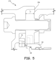
- FIG. 4 a cross-sectional view of an alternate arrangement 172 is shown.
- Sealing arrangement 172 shares some of the components with sealing arrangement 72, such as bearing compartment 56 and piston seal 74, but has other components that are different, such as mid-turbine frame 154.
- piston seal 74 is positioned between and is configured to contact sealing ring 162, inner case 160, and heat shield 68.
- mid-turbine frame 154 includes inner case 160 and seal ring 162.
- Inner case 160 includes flange 192 that extends radially inward from snap portion 84. While flange 192 could have a plain cylindrical shape, flange 192 has a scalloped radially inner end comprised of a plurality of fingers 194. Flange 192 axially constrains piston seal 74 and is the lateral annular contact surface that piston seal 74 is configured to contact in order to inhibit reverse flow (this configuration is not depicted in FIG. 4 ).
- Seal ring 162 includes rabbet 186 which axially and radially constrains piston seal 74.
- Rabbet 186 also serves as the lateral annular contact surface that piston seal 74 is configured to contact in order to inhibit normal flow (as depicted in FIG. 4 ) out of cavity 56. Due to the configuration of piston ring 74, the lateral contact surfaces of flange 192 and rabbet 186 are substantially perpendicular to the cylindrical contact surface of axial portion 90.
- bearing compartment 56 is assembled by fastening bearing case 64, seal support 66, and heat shield 68 together.
- most of mid-turbine frame 154 is assembled, such as rod 52 (shown in FIG. 2 ) and inner case 160, without seal ring 162. Then bearing compartment 56 and the partial mid-turbine frame 154 are connected.
- the uninstalled configuration of piston seal 74 has an inner diameter that is smaller than the outer diameter of axial portion 90. Therefore, piston seal 74 is expanded into an expanded configuration with an inner diameter that is larger than the outer diameter of axial portion 90.
- Piston seal 74 is positioned over heat shield 68 and allowed to contract in order to be in contact with axial portion 90. Piston seal 74 grips on to axial portion 90 due to diametric tension, although piston seal 74 is slidably movable along axial portion 90. Seal ring 162 is then snapped onto and fastened to inner case 160.
- sealing arrangement 172 as shown in FIG. 4 allow for piston seal 74 to be positioned between mid-turbine frame 154 and bearing compartment 56. Furthermore, assembly and disassembly of sealing arrangement 172 is relatively simpler and more reliable (as discussed further below). Also, there is much broader access to the contact surfaces on mid-turbine frame 154 and bearing compartment 56 for inspection and repair purposes.
- FIG. 5 a cross-sectional view of an incorrectly assembled sealing arrangement 172 is shown. More specifically, piston ring 74 has not been properly expanded and fit onto heat shield 68 prior to fastening seal ring 162 to inner case 160.
- the components and configuration of sealing arrangement 172 provides an instantly visible indication of incorrect assembly due to gap 196 between seal ring 162 and inner case 160. Gap 196 exists because of the relative axial lengths of three of the components of sealing arrangement 172.
- Length L 1 is the length of snap rim 82 that overlaps snap portion 84.
- Length L 2 is the length of axial portion 90 that extends beyond piston seal 74, or, in other words, length L 2 is the distance from the end of axial portion 90 to the proximal side of piston seal 74 when piston seal 74 is in the normal sealing position (shown in phantom).
- Length L 3 is the width of piston seal 74. Gap 196 exists because length L 1 is shorter than length L 2 added to length L3.
- drain pathway 198A extends axially through seal ring 162 proximate axial portion 90.
- Drain pathway 198B extends radially through seal ring 162 from rabbet 186 into pocket 199.
- Drain pathway 198C extends through the radially outer portion of seal ring 162 at an angle from pocket 199 proximate snap rim 82.
- Drain pathways 198A, 198B, and 198C allow for cooling air to purge stray oil that has collected around sealing arrangement 172. More specifically, drain pathway 198A allows oil to be blown out into rotor region 80 by cooling air passing by piston seal 74. In addition, oil that has accumulated between rabbet 186 and flange 192 is blown out through drain pathway 198B, pocket 199, and drain pathway 198C.
- sealing arrangement 272 shares the position of piston seal 74 with sealing arrangements 72 and 172, but further includes second seal 275.
- second seal 275 requires some differently-configured components from that of sealing arrangements 72 and 172.
- second seal 275 is a w-seal that is formed from a sheet of a high-temperature alloy, such as a nickel or cobalt alloy, which has been folded several times. W-seals are generally cheaper than piston seals and also seal better due to their ability to be installed in compression. Second seal 275 is positioned between mid-turbine frame 254 and bearing compartment 256. More specifically, second seal 275 is configured to contact the radially-extending annular side of second groove 287 in seal ring 262 on one end and an annular area of radial portion 288 of heat shield 268 on the other end. These two contact surfaces on second groove 287 and radial portion 288 are substantially parallel to each other and are distal from the contact surfaces for piston seal 74 (i.e. groove 86 and axial portion 290).
- a high-temperature alloy such as a nickel or cobalt alloy
- second seal 275 is positioned directly radially inwardly of piston seal 74 at the same position along longitudinal engine centerline axis C L (shown in FIG. 1 ) on opposite sides of compartment fastener 278. But second seal 275 is positioned in series with piston seal 74, downstream along the leakage flowpath from piston seal 74 during normal flow. In the case of reverse flow, second seal 275 is positioned upstream of piston seal 74 along the leakage flowpath. In order to better prevent reverse flow, second seal 275 is oriented such that reverse flow tends to force second seal 275 against second groove 287 and radial portion 288 more than in the case of normal flow.
- sealing arrangement 272 as shown in FIG. 7 allow for a cheap and efficient w-seal to be employed (i.e. second seal 275) that is protected by piston seal 74.
- sealing arrangement 272 can be better configured to inhibit reverse flow from rotor region 80 into cavity 265.
- second seal 275 can be oriented to better prevent normal flow by reversing its orientation.
- both piston seal 74 and second seal 275 can be piston seals.
- second seal 275 would be configured to contact the annular surface of the radially inner side of second groove 287 for inhibiting normal flow and the annular surface of the radially outer side of second groove 287 for inhibiting reverse flow.
- both piston seal 74 and second seal 275 can be w-seals in any combination of orientations.
- piston seal 74 can be constrained by the configuration of sealing arrangement 172 (shown in FIG. 4 ).
Landscapes
- Engineering & Computer Science (AREA)
- General Engineering & Computer Science (AREA)
- Mechanical Engineering (AREA)
- Chemical & Material Sciences (AREA)
- Combustion & Propulsion (AREA)
- Turbine Rotor Nozzle Sealing (AREA)
Claims (14)
- Dichtungsanordnung (272), umfassend:eine statische Turbinenstruktur, die einen Dichtring (262) mit einer radial nach innen weisenden Nut (86) mit einer ringförmigen ersten Kontaktfläche und einer ringförmigen zweiten Kontaktfläche an dem Dichtring (262), die distal und radial einwärts von der ersten Kontaktfläche liegt, aufweist;eine Lagerkammerstruktur (256), die durch die statische Turbinenstruktur umgeben ist, die ein Wärmeschild (268) aufweist, wobei das Wärmeschild einen axialen Abschnitt (290) mit einer zylindrischen dritten Kontaktfläche und einen mit dem axialen Abschnitt (290) verbunden radialen Abschnitt (288) mit einer ringförmigen vierten Kontaktfläche, die distal und radial einwärts von der dritten Kontaktfläche liegt, umfasst;einen Hohlraum (265) zwischen der statischen Turbinenstruktur und der Lagerkammerstruktur (256);eine erste Dichtung (74), die zwischen der statischen Turbinenstruktur und der Lagerkammerstruktur (256) positioniert ist, wobei die erste Dichtung mit der ersten Kontaktfläche und der dritten Kontaktfläche in Kontakt steht;eine zweite Dichtung (275), die zwischen der statischen Turbinenstruktur und der Lagerkammerstruktur (256) positioniert ist, wobei die zweite Dichtung mit der zweiten Kontaktfläche und der vierten Kontaktfläche in Kontakt steht; undeine Befestigungselementkammer (281) zwischen dem Dichtring und der Lagerkammerstruktur und begrenzt durch die erste Dichtung und die zweite Dichtung.
- Dichtungsanordnung (272) nach Anspruch 1, wobei die erste Dichtung eine Vorwärtsfluidströmung von dem Hohlraum (265) in die Befestigungselementkammer (281) dadurch hemmt, dass sie mit der ersten Kontaktfläche und der dritten Kontaktfläche in Kontakt steht, und die zweite Dichtung die Vorwärtsfluidströmung von der Befestigungselementkammer in eine Rotorkammer dadurch hemmt, dass sie mit der zweiten Kontaktfläche und der vierten Kontaktfläche in Kontakt steht.
- Dichtungsanordnung (272) nach Anspruch 2, wobei die erste Dichtung eine Kolbendichtung ist und wobei vorzugsweise die zweite Dichtung eine W-Dichtung (275) ist.
- Dichtungsanordnung (272) nach Anspruch 3, wobei die W-Dichtung (275) dazu neigt, im Einsatz durch eine Rückwärtsfluidströmung von der Rotorkammer in die Befestigungselementkammer (281) ausgedehnt zu werden.
- Dichtungsanordnung (272) nach Anspruch 4, wobei die statische Turbinenstruktur ferner Folgendes umfasst:
eine ringförmige fünfte Kontaktfläche in der Nut gegenüber der ersten Kontaktfläche, die die Kolbendichtung im Einsatz berührt, um die Rückwärtsfluidströmung von der Befestigungselementkammer in den Hohlraum dadurch zu hemmen, dass sie mit der dritten Kontaktfläche und der fünften Kontaktfläche in Kontakt steht. - Dichtungsanordnung (272) nach Anspruch 5, wobei die statische Turbinenstruktur ferner Folgendes umfasst:ein Innengehäuse (60), wobei der Dichtring (262) an dem Innengehäuse befestigt ist;wobei sich die erste und die zweite Kontaktfläche an dem Dichtring befinden und sich die fünfte Kontaktfläche an dem Innengehäuse befindet.
- Dichtungsanordnung (272) nach einem der vorstehenden Ansprüche, wobei die zweite Dichtung direkt radial einwärts von der ersten Dichtung liegt.
- Dichtungsanordnung (272) nach einem der vorstehenden Ansprüche, wobei die statische Turbinenstruktur ferner Folgendes umfasst:ein Innengehäuse, wobei der Dichtring (262) an dem Innengehäuse befestigt ist;wobei sich die erste und die zweite Kontaktfläche an dem Dichtring (262) befinden und wobei vorzugsweise die Kolbendichtung (74) in der Nut (86) in dem Dichtring positioniert ist, der im Wesentlichen eine erste Seite, eine zweite Seite und eine dritte Seite der Kolbendichtung umgibt.
- Gasturbinentriebwerk (10), das entlang einer Achse angeordnet ist, wobei das Gasturbinentriebwerk Folgendes umfasst:einen Fan (12);einen ersten Verdichter (14) stromabwärts des Fans;einen zweiten Verdichter (16) stromabwärts des ersten Verdichters;eine Brennkammer (18) stromabwärts des zweiten Verdichters;eine erste Turbine (20) stromabwärts der Brennkammer;eine zweite Turbine (22) stromabwärts der ersten Turbine;die Dichtungsanordnung (272) nach Anspruch 1; undeinen Strömungspfad, der sich von dem Hohlraum (265) zu einer von der ersten Turbine und der zweiten Turbine erstreckt, wobei der Strömungspfad durch die statische Turbinenstruktur und die Lagerkammerstruktur (256) begrenzt ist.
- Gasturbinentriebwerk nach Anspruch 9, wobei die erste Dichtung und die zweite Dichtung an einer axialen Position positioniert sind, wobei die erste Dichtung an einer ersten radialen Position von der Achse positioniert ist und die zweite Dichtung an einer zweiten radialen Position, die näher an der Achse liegt als die erste radiale Position, positioniert ist.
- Gasturbinentriebwerk nach Ansprüchen 9 oder 10, wobei die erste Dichtung eine Kolbendichtung (74) ist und die zweite Dichtung eine W-Dichtung (275) ist und wobei vorzugsweise die zweite Dichtung dazu neigt, sich im Einsatz mit einer Strömung durch den Strömungspfad von einer von der ersten Turbine und der zweiten Turbine in den Hohlraum auszudehnen.
- Gasturbinentriebwerk nach Ansprüchen 9 bis 11, wobei die statische Turbinenstruktur stromabwärts der ersten Turbine und stromaufwärts der zweiten Turbine positioniert ist.
- Gasturbinentriebwerk nach Ansprüchen 9 bis 12, wobei die statische Turbinenstruktur ferner Folgendes umfasst:ein Gasrohr;eine Verkleidung, die das Gasrohr umgibt;ein Innengehäuse (60), das mit dem Gasrohr verbunden ist; undeinen Dichtring (62), der an dem Innengehäuse befestigt ist.
- Gasturbinentriebwerk nach Ansprüchen 9 bis 13, wobei während des Betriebs des Gasturbinentriebwerks:die erste Dichtung die erste Kontaktfläche der statischen Turbinenstruktur und die dritte Kontaktfläche der Lagerkammerstruktur während des Betriebs des Gasturbinentriebwerks berührt; unddie zweite Dichtung die zweite Kontaktfläche der statischen Turbinenstruktur und die vierte Kontaktfläche der Lagerkammerstruktur berührt.
Applications Claiming Priority (1)
| Application Number | Priority Date | Filing Date | Title |
|---|---|---|---|
| US14/603,033 US10161256B2 (en) | 2015-01-22 | 2015-01-22 | Seal with backup seal |
Publications (2)
| Publication Number | Publication Date |
|---|---|
| EP3048261A1 EP3048261A1 (de) | 2016-07-27 |
| EP3048261B1 true EP3048261B1 (de) | 2024-05-01 |
Family
ID=55177886
Family Applications (1)
| Application Number | Title | Priority Date | Filing Date |
|---|---|---|---|
| EP16152189.3A Active EP3048261B1 (de) | 2015-01-22 | 2016-01-21 | Statische turbinendichtung mit hilfsdichtung |
Country Status (2)
| Country | Link |
|---|---|
| US (1) | US10161256B2 (de) |
| EP (1) | EP3048261B1 (de) |
Families Citing this family (7)
| Publication number | Priority date | Publication date | Assignee | Title |
|---|---|---|---|---|
| US10215098B2 (en) * | 2015-01-22 | 2019-02-26 | United Technologies Corporation | Bearing compartment seal |
| FR3040737B1 (fr) * | 2015-09-04 | 2017-09-22 | Snecma | Ensemble propulsif muni de parties de carter decouplables |
| US10677168B2 (en) | 2017-12-13 | 2020-06-09 | Raytheon Technologies Corporation | Seal retention assembly for gas turbine engine |
| US11391179B2 (en) | 2019-02-12 | 2022-07-19 | Pratt & Whitney Canada Corp. | Gas turbine engine with bearing support structure |
| US11346249B2 (en) | 2019-03-05 | 2022-05-31 | Pratt & Whitney Canada Corp. | Gas turbine engine with feed pipe for bearing housing |
| US11280208B2 (en) | 2019-08-14 | 2022-03-22 | Pratt & Whitney Canada Corp. | Labyrinth seal assembly |
| CN115013161B (zh) * | 2022-06-29 | 2025-02-14 | 中国航发湖南动力机械研究所 | 一种涡轮级间支承结构、燃气涡轮发动机 |
Family Cites Families (43)
| Publication number | Priority date | Publication date | Assignee | Title |
|---|---|---|---|---|
| US3527054A (en) | 1969-01-23 | 1970-09-08 | Gen Electric | Pressurization of lubrication sumps in gas turbine engines |
| US3915521A (en) | 1974-09-30 | 1975-10-28 | United Technologies Corp | Lubricated radial bearing assembly |
| US4369016A (en) | 1979-12-21 | 1983-01-18 | United Technologies Corporation | Turbine intermediate case |
| US4321007A (en) | 1979-12-21 | 1982-03-23 | United Technologies Corporation | Outer case cooling for a turbine intermediate case |
| DE3003470C2 (de) * | 1980-01-31 | 1982-02-25 | MTU Motoren- und Turbinen-Union München GmbH, 8000 München | Turbinenleitschaufelaufhängung für Gasturbinenstrahltriebwerke |
| GB2075614B (en) * | 1980-05-10 | 1984-11-28 | Rolls Royce | Annular seal |
| US4406459A (en) | 1982-06-18 | 1983-09-27 | United Technologies Corporation | Oil weepage return for carbon seal plates |
| US4561246A (en) | 1983-12-23 | 1985-12-31 | United Technologies Corporation | Bearing compartment for a gas turbine engine |
| US5622438A (en) | 1995-07-12 | 1997-04-22 | United Technologies Corporation | Fire resistant bearing compartment cover |
| US6131914A (en) | 1996-08-30 | 2000-10-17 | United Technologies Corporation | Gas turbine engine bearing compartment seal |
| US6076835A (en) * | 1997-05-21 | 2000-06-20 | Allison Advanced Development Company | Interstage van seal apparatus |
| US6916154B2 (en) | 2003-04-29 | 2005-07-12 | Pratt & Whitney Canada Corp. | Diametrically energized piston ring |
| GB0517833D0 (en) | 2005-09-02 | 2005-10-12 | Rolls Royce Plc | A seal arrangement and a method of seal assembly |
| US8210316B2 (en) | 2006-12-12 | 2012-07-03 | United Technologies Corporation | Oil scavenge system for a gas turbine engine |
| US7984911B2 (en) | 2008-01-17 | 2011-07-26 | United Technologies Corporation | Face seal for gas turbine engine |
| US7946590B2 (en) | 2008-01-17 | 2011-05-24 | United Technologies Corporation | Face seal for gas turbine engine |
| US8061969B2 (en) | 2008-11-28 | 2011-11-22 | Pratt & Whitney Canada Corp. | Mid turbine frame system for gas turbine engine |
| US8099962B2 (en) | 2008-11-28 | 2012-01-24 | Pratt & Whitney Canada Corp. | Mid turbine frame system and radial locator for radially centering a bearing for gas turbine engine |
| US8371127B2 (en) | 2009-10-01 | 2013-02-12 | Pratt & Whitney Canada Corp. | Cooling air system for mid turbine frame |
| US8453464B2 (en) | 2009-10-01 | 2013-06-04 | Pratt & Whitney Canada Corp. | Air metering device for gas turbine engine |
| US8747054B2 (en) | 2011-01-24 | 2014-06-10 | United Technologies Corporation | Bearing system for gas turbine engine |
| US8777563B2 (en) * | 2011-01-31 | 2014-07-15 | General Electric Company | Axial brush seal |
| US20130019225A1 (en) | 2011-07-11 | 2013-01-17 | Microsoft Corporation | Incremental Inferences for Developing Data Models |
| US9316119B2 (en) | 2011-09-15 | 2016-04-19 | United Technologies Corporation | Turbomachine secondary seal assembly |
| US10598222B2 (en) | 2012-01-03 | 2020-03-24 | New Way Machine Components, Inc. | Air bearing for use as seal |
| US8794009B2 (en) | 2012-01-31 | 2014-08-05 | United Technologies Corporation | Gas turbine engine buffer system |
| US9140137B2 (en) | 2012-01-31 | 2015-09-22 | United Technologies Corporation | Gas turbine engine mid turbine frame bearing support |
| US8366382B1 (en) | 2012-01-31 | 2013-02-05 | United Technologies Corporation | Mid-turbine frame buffer system |
| US9133723B2 (en) * | 2012-05-21 | 2015-09-15 | United Technologies Corporation | Shield system for gas turbine engine |
| US9851008B2 (en) | 2012-06-04 | 2017-12-26 | United Technologies Corporation | Seal land for static structure of a gas turbine engine |
| US9394915B2 (en) * | 2012-06-04 | 2016-07-19 | United Technologies Corporation | Seal land for static structure of a gas turbine engine |
| US20140010649A1 (en) * | 2012-07-09 | 2014-01-09 | United Technologies Corporation | Mid-turbine frame hpt seal support meshing |
| US9328626B2 (en) * | 2012-08-21 | 2016-05-03 | United Technologies Corporation | Annular turbomachine seal and heat shield |
| WO2014051691A1 (en) | 2012-09-27 | 2014-04-03 | United Technologies Corporation | Buffer airflow to bearing compartment |
| US9726031B2 (en) | 2012-09-28 | 2017-08-08 | United Technologies Corporation | Piston ring coated carbon seal |
| US20140140824A1 (en) | 2012-10-26 | 2014-05-22 | United Technologies Corporation | Oil system bearing compartment architecture for gas turbine engine |
| FR2998922B1 (fr) | 2012-12-05 | 2018-06-15 | Safran Aircraft Engines | Etancheite d'enceintes de turbomachine realisee par joint a brosse et labyrinthe |
| US9605596B2 (en) * | 2013-03-08 | 2017-03-28 | United Technologies Corporation | Duct blocker seal assembly for a gas turbine engine |
| WO2014138617A1 (en) | 2013-03-08 | 2014-09-12 | United Technologies Corporation | Fluid-cooled seal arrangement for a gas turbine engine |
| EP2971688B1 (de) | 2013-03-14 | 2018-11-28 | United Technologies Corporation | Gasturbinentriebwerk mit einer hitzeschildabdichtung und ein verfahren zum einbau dieser abdichtung |
| EP2986824B1 (de) | 2013-04-18 | 2020-05-27 | United Technologies Corporation | Turbinenminischeibenstossfänger für einen gasturbinenmotor |
| US10107118B2 (en) | 2013-06-28 | 2018-10-23 | United Technologies Corporation | Flow discourager for vane sealing area of a gas turbine engine |
| US9995161B2 (en) | 2014-11-12 | 2018-06-12 | Borgwarner Inc. | Modular turbocharger clearance seal |
-
2015
- 2015-01-22 US US14/603,033 patent/US10161256B2/en active Active
-
2016
- 2016-01-21 EP EP16152189.3A patent/EP3048261B1/de active Active
Also Published As
| Publication number | Publication date |
|---|---|
| EP3048261A1 (de) | 2016-07-27 |
| US20160215638A1 (en) | 2016-07-28 |
| US10161256B2 (en) | 2018-12-25 |
Similar Documents
| Publication | Publication Date | Title |
|---|---|---|
| EP3048261B1 (de) | Statische turbinendichtung mit hilfsdichtung | |
| EP3048269B1 (de) | Dichtung für lagerkammer | |
| US10088049B2 (en) | Thermally protected seal assembly | |
| EP2984296B1 (de) | Aussendichtung für eine turbinenschaufel mit sekundärluftabdichtung | |
| US10487943B2 (en) | Multi-ply seal ring | |
| EP2949874B1 (de) | Doppelwandige dichtungsanordnung | |
| US10253645B2 (en) | Blade outer air seal with secondary air sealing | |
| EP3048268B1 (de) | Mit flansch eingeschlossene dichtungsanordnung | |
| US10443422B2 (en) | Gas turbine engine with a rim seal between the rotor and stator | |
| US10309255B2 (en) | Blade outer air seal cooling passage | |
| EP3056680B1 (de) | Leckageluftsysteme für turbomaschinen | |
| US10598035B2 (en) | Intershaft sealing systems for gas turbine engines and methods for assembling the same | |
| US10113436B2 (en) | Chordal seal with sudden expansion/contraction | |
| US10301956B2 (en) | Seal assembly for sealing an axial gap between components | |
| US10273821B2 (en) | Advanced stationary sealing cooled cross-section for axial retention of ceramic matrix composite shrouds | |
| US20180283194A1 (en) | Method and system for a pressure activated cap seal | |
| US10598036B2 (en) | Assembly for sealing a gap between components of a turbine engine | |
| EP3073060B1 (de) | Dichtungshalterungsstrukturen für turbomaschinen |
Legal Events
| Date | Code | Title | Description |
|---|---|---|---|
| PUAI | Public reference made under article 153(3) epc to a published international application that has entered the european phase |
Free format text: ORIGINAL CODE: 0009012 |
|
| AK | Designated contracting states |
Kind code of ref document: A1 Designated state(s): AL AT BE BG CH CY CZ DE DK EE ES FI FR GB GR HR HU IE IS IT LI LT LU LV MC MK MT NL NO PL PT RO RS SE SI SK SM TR |
|
| AX | Request for extension of the european patent |
Extension state: BA ME |
|
| RAP1 | Party data changed (applicant data changed or rights of an application transferred) |
Owner name: UNITED TECHNOLOGIES CORPORATION |
|
| STAA | Information on the status of an ep patent application or granted ep patent |
Free format text: STATUS: REQUEST FOR EXAMINATION WAS MADE |
|
| 17P | Request for examination filed |
Effective date: 20170127 |
|
| RBV | Designated contracting states (corrected) |
Designated state(s): AL AT BE BG CH CY CZ DE DK EE ES FI FR GB GR HR HU IE IS IT LI LT LU LV MC MK MT NL NO PL PT RO RS SE SI SK SM TR |
|
| STAA | Information on the status of an ep patent application or granted ep patent |
Free format text: STATUS: EXAMINATION IS IN PROGRESS |
|
| 17Q | First examination report despatched |
Effective date: 20200619 |
|
| RAP1 | Party data changed (applicant data changed or rights of an application transferred) |
Owner name: RAYTHEON TECHNOLOGIES CORPORATION |
|
| GRAP | Despatch of communication of intention to grant a patent |
Free format text: ORIGINAL CODE: EPIDOSNIGR1 |
|
| STAA | Information on the status of an ep patent application or granted ep patent |
Free format text: STATUS: GRANT OF PATENT IS INTENDED |
|
| RAP3 | Party data changed (applicant data changed or rights of an application transferred) |
Owner name: RTX CORPORATION |
|
| INTG | Intention to grant announced |
Effective date: 20231031 |
|
| GRAS | Grant fee paid |
Free format text: ORIGINAL CODE: EPIDOSNIGR3 |
|
| RIN1 | Information on inventor provided before grant (corrected) |
Inventor name: MAX, SETH Inventor name: PORTER, STEVEN D. |
|
| GRAA | (expected) grant |
Free format text: ORIGINAL CODE: 0009210 |
|
| STAA | Information on the status of an ep patent application or granted ep patent |
Free format text: STATUS: THE PATENT HAS BEEN GRANTED |
|
| AK | Designated contracting states |
Kind code of ref document: B1 Designated state(s): AL AT BE BG CH CY CZ DE DK EE ES FI FR GB GR HR HU IE IS IT LI LT LU LV MC MK MT NL NO PL PT RO RS SE SI SK SM TR |
|
| REG | Reference to a national code |
Ref country code: GB Ref legal event code: FG4D |
|
| RIN1 | Information on inventor provided before grant (corrected) |
Inventor name: MAX, SETH Inventor name: PORTER, STEVEN D. |
|
| REG | Reference to a national code |
Ref country code: CH Ref legal event code: EP |
|
| REG | Reference to a national code |
Ref country code: IE Ref legal event code: FG4D |
|
| REG | Reference to a national code |
Ref country code: DE Ref legal event code: R096 Ref document number: 602016087225 Country of ref document: DE |
|
| REG | Reference to a national code |
Ref country code: LT Ref legal event code: MG9D |
|
| REG | Reference to a national code |
Ref country code: NL Ref legal event code: MP Effective date: 20240501 |
|
| PG25 | Lapsed in a contracting state [announced via postgrant information from national office to epo] |
Ref country code: IS Free format text: LAPSE BECAUSE OF FAILURE TO SUBMIT A TRANSLATION OF THE DESCRIPTION OR TO PAY THE FEE WITHIN THE PRESCRIBED TIME-LIMIT Effective date: 20240901 |
|
| PG25 | Lapsed in a contracting state [announced via postgrant information from national office to epo] |
Ref country code: BG Free format text: LAPSE BECAUSE OF FAILURE TO SUBMIT A TRANSLATION OF THE DESCRIPTION OR TO PAY THE FEE WITHIN THE PRESCRIBED TIME-LIMIT Effective date: 20240501 |
|
| PG25 | Lapsed in a contracting state [announced via postgrant information from national office to epo] |
Ref country code: FI Free format text: LAPSE BECAUSE OF FAILURE TO SUBMIT A TRANSLATION OF THE DESCRIPTION OR TO PAY THE FEE WITHIN THE PRESCRIBED TIME-LIMIT Effective date: 20240501 Ref country code: HR Free format text: LAPSE BECAUSE OF FAILURE TO SUBMIT A TRANSLATION OF THE DESCRIPTION OR TO PAY THE FEE WITHIN THE PRESCRIBED TIME-LIMIT Effective date: 20240501 |
|
| PG25 | Lapsed in a contracting state [announced via postgrant information from national office to epo] |
Ref country code: GR Free format text: LAPSE BECAUSE OF FAILURE TO SUBMIT A TRANSLATION OF THE DESCRIPTION OR TO PAY THE FEE WITHIN THE PRESCRIBED TIME-LIMIT Effective date: 20240802 |
|
| PG25 | Lapsed in a contracting state [announced via postgrant information from national office to epo] |
Ref country code: PT Free format text: LAPSE BECAUSE OF FAILURE TO SUBMIT A TRANSLATION OF THE DESCRIPTION OR TO PAY THE FEE WITHIN THE PRESCRIBED TIME-LIMIT Effective date: 20240902 |
|
| REG | Reference to a national code |
Ref country code: AT Ref legal event code: MK05 Ref document number: 1682586 Country of ref document: AT Kind code of ref document: T Effective date: 20240501 |
|
| PG25 | Lapsed in a contracting state [announced via postgrant information from national office to epo] |
Ref country code: NL Free format text: LAPSE BECAUSE OF FAILURE TO SUBMIT A TRANSLATION OF THE DESCRIPTION OR TO PAY THE FEE WITHIN THE PRESCRIBED TIME-LIMIT Effective date: 20240501 |
|
| PG25 | Lapsed in a contracting state [announced via postgrant information from national office to epo] |
Ref country code: ES Free format text: LAPSE BECAUSE OF FAILURE TO SUBMIT A TRANSLATION OF THE DESCRIPTION OR TO PAY THE FEE WITHIN THE PRESCRIBED TIME-LIMIT Effective date: 20240501 |
|
| PG25 | Lapsed in a contracting state [announced via postgrant information from national office to epo] |
Ref country code: AT Free format text: LAPSE BECAUSE OF FAILURE TO SUBMIT A TRANSLATION OF THE DESCRIPTION OR TO PAY THE FEE WITHIN THE PRESCRIBED TIME-LIMIT Effective date: 20240501 |
|
| PG25 | Lapsed in a contracting state [announced via postgrant information from national office to epo] |
Ref country code: PL Free format text: LAPSE BECAUSE OF FAILURE TO SUBMIT A TRANSLATION OF THE DESCRIPTION OR TO PAY THE FEE WITHIN THE PRESCRIBED TIME-LIMIT Effective date: 20240501 |
|
| PG25 | Lapsed in a contracting state [announced via postgrant information from national office to epo] |
Ref country code: LV Free format text: LAPSE BECAUSE OF FAILURE TO SUBMIT A TRANSLATION OF THE DESCRIPTION OR TO PAY THE FEE WITHIN THE PRESCRIBED TIME-LIMIT Effective date: 20240501 |
|
| PG25 | Lapsed in a contracting state [announced via postgrant information from national office to epo] |
Ref country code: PT Free format text: LAPSE BECAUSE OF FAILURE TO SUBMIT A TRANSLATION OF THE DESCRIPTION OR TO PAY THE FEE WITHIN THE PRESCRIBED TIME-LIMIT Effective date: 20240902 Ref country code: PL Free format text: LAPSE BECAUSE OF FAILURE TO SUBMIT A TRANSLATION OF THE DESCRIPTION OR TO PAY THE FEE WITHIN THE PRESCRIBED TIME-LIMIT Effective date: 20240501 Ref country code: NO Free format text: LAPSE BECAUSE OF FAILURE TO SUBMIT A TRANSLATION OF THE DESCRIPTION OR TO PAY THE FEE WITHIN THE PRESCRIBED TIME-LIMIT Effective date: 20240801 Ref country code: NL Free format text: LAPSE BECAUSE OF FAILURE TO SUBMIT A TRANSLATION OF THE DESCRIPTION OR TO PAY THE FEE WITHIN THE PRESCRIBED TIME-LIMIT Effective date: 20240501 Ref country code: LV Free format text: LAPSE BECAUSE OF FAILURE TO SUBMIT A TRANSLATION OF THE DESCRIPTION OR TO PAY THE FEE WITHIN THE PRESCRIBED TIME-LIMIT Effective date: 20240501 Ref country code: IS Free format text: LAPSE BECAUSE OF FAILURE TO SUBMIT A TRANSLATION OF THE DESCRIPTION OR TO PAY THE FEE WITHIN THE PRESCRIBED TIME-LIMIT Effective date: 20240901 Ref country code: HR Free format text: LAPSE BECAUSE OF FAILURE TO SUBMIT A TRANSLATION OF THE DESCRIPTION OR TO PAY THE FEE WITHIN THE PRESCRIBED TIME-LIMIT Effective date: 20240501 Ref country code: GR Free format text: LAPSE BECAUSE OF FAILURE TO SUBMIT A TRANSLATION OF THE DESCRIPTION OR TO PAY THE FEE WITHIN THE PRESCRIBED TIME-LIMIT Effective date: 20240802 Ref country code: FI Free format text: LAPSE BECAUSE OF FAILURE TO SUBMIT A TRANSLATION OF THE DESCRIPTION OR TO PAY THE FEE WITHIN THE PRESCRIBED TIME-LIMIT Effective date: 20240501 Ref country code: ES Free format text: LAPSE BECAUSE OF FAILURE TO SUBMIT A TRANSLATION OF THE DESCRIPTION OR TO PAY THE FEE WITHIN THE PRESCRIBED TIME-LIMIT Effective date: 20240501 Ref country code: BG Free format text: LAPSE BECAUSE OF FAILURE TO SUBMIT A TRANSLATION OF THE DESCRIPTION OR TO PAY THE FEE WITHIN THE PRESCRIBED TIME-LIMIT Effective date: 20240501 Ref country code: AT Free format text: LAPSE BECAUSE OF FAILURE TO SUBMIT A TRANSLATION OF THE DESCRIPTION OR TO PAY THE FEE WITHIN THE PRESCRIBED TIME-LIMIT Effective date: 20240501 Ref country code: RS Free format text: LAPSE BECAUSE OF FAILURE TO SUBMIT A TRANSLATION OF THE DESCRIPTION OR TO PAY THE FEE WITHIN THE PRESCRIBED TIME-LIMIT Effective date: 20240801 |
|
| PG25 | Lapsed in a contracting state [announced via postgrant information from national office to epo] |
Ref country code: DK Free format text: LAPSE BECAUSE OF FAILURE TO SUBMIT A TRANSLATION OF THE DESCRIPTION OR TO PAY THE FEE WITHIN THE PRESCRIBED TIME-LIMIT Effective date: 20240501 |
|
| PG25 | Lapsed in a contracting state [announced via postgrant information from national office to epo] |
Ref country code: EE Free format text: LAPSE BECAUSE OF FAILURE TO SUBMIT A TRANSLATION OF THE DESCRIPTION OR TO PAY THE FEE WITHIN THE PRESCRIBED TIME-LIMIT Effective date: 20240501 |
|
| PG25 | Lapsed in a contracting state [announced via postgrant information from national office to epo] |
Ref country code: CZ Free format text: LAPSE BECAUSE OF FAILURE TO SUBMIT A TRANSLATION OF THE DESCRIPTION OR TO PAY THE FEE WITHIN THE PRESCRIBED TIME-LIMIT Effective date: 20240501 |
|
| PG25 | Lapsed in a contracting state [announced via postgrant information from national office to epo] |
Ref country code: RO Free format text: LAPSE BECAUSE OF FAILURE TO SUBMIT A TRANSLATION OF THE DESCRIPTION OR TO PAY THE FEE WITHIN THE PRESCRIBED TIME-LIMIT Effective date: 20240501 Ref country code: SK Free format text: LAPSE BECAUSE OF FAILURE TO SUBMIT A TRANSLATION OF THE DESCRIPTION OR TO PAY THE FEE WITHIN THE PRESCRIBED TIME-LIMIT Effective date: 20240501 |
|
| PG25 | Lapsed in a contracting state [announced via postgrant information from national office to epo] |
Ref country code: SM Free format text: LAPSE BECAUSE OF FAILURE TO SUBMIT A TRANSLATION OF THE DESCRIPTION OR TO PAY THE FEE WITHIN THE PRESCRIBED TIME-LIMIT Effective date: 20240501 |
|
| PG25 | Lapsed in a contracting state [announced via postgrant information from national office to epo] |
Ref country code: SM Free format text: LAPSE BECAUSE OF FAILURE TO SUBMIT A TRANSLATION OF THE DESCRIPTION OR TO PAY THE FEE WITHIN THE PRESCRIBED TIME-LIMIT Effective date: 20240501 Ref country code: SK Free format text: LAPSE BECAUSE OF FAILURE TO SUBMIT A TRANSLATION OF THE DESCRIPTION OR TO PAY THE FEE WITHIN THE PRESCRIBED TIME-LIMIT Effective date: 20240501 Ref country code: RO Free format text: LAPSE BECAUSE OF FAILURE TO SUBMIT A TRANSLATION OF THE DESCRIPTION OR TO PAY THE FEE WITHIN THE PRESCRIBED TIME-LIMIT Effective date: 20240501 Ref country code: EE Free format text: LAPSE BECAUSE OF FAILURE TO SUBMIT A TRANSLATION OF THE DESCRIPTION OR TO PAY THE FEE WITHIN THE PRESCRIBED TIME-LIMIT Effective date: 20240501 Ref country code: DK Free format text: LAPSE BECAUSE OF FAILURE TO SUBMIT A TRANSLATION OF THE DESCRIPTION OR TO PAY THE FEE WITHIN THE PRESCRIBED TIME-LIMIT Effective date: 20240501 Ref country code: CZ Free format text: LAPSE BECAUSE OF FAILURE TO SUBMIT A TRANSLATION OF THE DESCRIPTION OR TO PAY THE FEE WITHIN THE PRESCRIBED TIME-LIMIT Effective date: 20240501 |
|
| REG | Reference to a national code |
Ref country code: DE Ref legal event code: R097 Ref document number: 602016087225 Country of ref document: DE |
|
| PG25 | Lapsed in a contracting state [announced via postgrant information from national office to epo] |
Ref country code: IT Free format text: LAPSE BECAUSE OF FAILURE TO SUBMIT A TRANSLATION OF THE DESCRIPTION OR TO PAY THE FEE WITHIN THE PRESCRIBED TIME-LIMIT Effective date: 20240501 |
|
| PLBE | No opposition filed within time limit |
Free format text: ORIGINAL CODE: 0009261 |
|
| STAA | Information on the status of an ep patent application or granted ep patent |
Free format text: STATUS: NO OPPOSITION FILED WITHIN TIME LIMIT |
|
| 26N | No opposition filed |
Effective date: 20250204 |
|
| PGFP | Annual fee paid to national office [announced via postgrant information from national office to epo] |
Ref country code: DE Payment date: 20241218 Year of fee payment: 10 |
|
| PG25 | Lapsed in a contracting state [announced via postgrant information from national office to epo] |
Ref country code: SI Free format text: LAPSE BECAUSE OF FAILURE TO SUBMIT A TRANSLATION OF THE DESCRIPTION OR TO PAY THE FEE WITHIN THE PRESCRIBED TIME-LIMIT Effective date: 20240501 |
|
| REG | Reference to a national code |
Ref country code: CH Ref legal event code: PL |
|
| PG25 | Lapsed in a contracting state [announced via postgrant information from national office to epo] |
Ref country code: SE Free format text: LAPSE BECAUSE OF FAILURE TO SUBMIT A TRANSLATION OF THE DESCRIPTION OR TO PAY THE FEE WITHIN THE PRESCRIBED TIME-LIMIT Effective date: 20240501 |
|
| PG25 | Lapsed in a contracting state [announced via postgrant information from national office to epo] |
Ref country code: LU Free format text: LAPSE BECAUSE OF NON-PAYMENT OF DUE FEES Effective date: 20250121 Ref country code: MC Free format text: LAPSE BECAUSE OF FAILURE TO SUBMIT A TRANSLATION OF THE DESCRIPTION OR TO PAY THE FEE WITHIN THE PRESCRIBED TIME-LIMIT Effective date: 20240501 |
|
| PG25 | Lapsed in a contracting state [announced via postgrant information from national office to epo] |
Ref country code: BE Free format text: LAPSE BECAUSE OF NON-PAYMENT OF DUE FEES Effective date: 20250131 |
|
| PG25 | Lapsed in a contracting state [announced via postgrant information from national office to epo] |
Ref country code: CH Free format text: LAPSE BECAUSE OF NON-PAYMENT OF DUE FEES Effective date: 20250131 |
|
| REG | Reference to a national code |
Ref country code: BE Ref legal event code: MM Effective date: 20250131 |
|
| PGFP | Annual fee paid to national office [announced via postgrant information from national office to epo] |
Ref country code: GB Payment date: 20251220 Year of fee payment: 11 |
|
| PGFP | Annual fee paid to national office [announced via postgrant information from national office to epo] |
Ref country code: FR Payment date: 20251217 Year of fee payment: 11 |
|
| PG25 | Lapsed in a contracting state [announced via postgrant information from national office to epo] |
Ref country code: IE Free format text: LAPSE BECAUSE OF NON-PAYMENT OF DUE FEES Effective date: 20250121 |