EP3048252A1 - Fan blade - Google Patents
Fan blade Download PDFInfo
- Publication number
- EP3048252A1 EP3048252A1 EP15200478.4A EP15200478A EP3048252A1 EP 3048252 A1 EP3048252 A1 EP 3048252A1 EP 15200478 A EP15200478 A EP 15200478A EP 3048252 A1 EP3048252 A1 EP 3048252A1
- Authority
- EP
- European Patent Office
- Prior art keywords
- region
- membrane
- fan blade
- thickness
- root
- Prior art date
- Legal status (The legal status is an assumption and is not a legal conclusion. Google has not performed a legal analysis and makes no representation as to the accuracy of the status listed.)
- Withdrawn
Links
- 239000012528 membrane Substances 0.000 claims abstract description 106
- 238000000034 method Methods 0.000 claims description 36
- 230000007704 transition Effects 0.000 claims description 10
- 238000009792 diffusion process Methods 0.000 claims description 9
- 238000004519 manufacturing process Methods 0.000 claims description 7
- 239000000463 material Substances 0.000 description 7
- RTAQQCXQSZGOHL-UHFFFAOYSA-N Titanium Chemical compound [Ti] RTAQQCXQSZGOHL-UHFFFAOYSA-N 0.000 description 4
- 229910052719 titanium Inorganic materials 0.000 description 4
- 239000010936 titanium Substances 0.000 description 4
- 239000007789 gas Substances 0.000 description 3
- 239000011261 inert gas Substances 0.000 description 2
- 238000011109 contamination Methods 0.000 description 1
- 238000005530 etching Methods 0.000 description 1
- 239000000446 fuel Substances 0.000 description 1
- 238000003754 machining Methods 0.000 description 1
- XLYOFNOQVPJJNP-UHFFFAOYSA-N water Substances O XLYOFNOQVPJJNP-UHFFFAOYSA-N 0.000 description 1
- 239000013585 weight reducing agent Substances 0.000 description 1
- 229910052727 yttrium Inorganic materials 0.000 description 1
- VWQVUPCCIRVNHF-UHFFFAOYSA-N yttrium atom Chemical compound [Y] VWQVUPCCIRVNHF-UHFFFAOYSA-N 0.000 description 1
Images


Classifications
-
- F—MECHANICAL ENGINEERING; LIGHTING; HEATING; WEAPONS; BLASTING
- F01—MACHINES OR ENGINES IN GENERAL; ENGINE PLANTS IN GENERAL; STEAM ENGINES
- F01D—NON-POSITIVE DISPLACEMENT MACHINES OR ENGINES, e.g. STEAM TURBINES
- F01D5/00—Blades; Blade-carrying members; Heating, heat-insulating, cooling or antivibration means on the blades or the members
- F01D5/12—Blades
- F01D5/14—Form or construction
- F01D5/18—Hollow blades, i.e. blades with cooling or heating channels or cavities; Heating, heat-insulating or cooling means on blades
-
- F—MECHANICAL ENGINEERING; LIGHTING; HEATING; WEAPONS; BLASTING
- F01—MACHINES OR ENGINES IN GENERAL; ENGINE PLANTS IN GENERAL; STEAM ENGINES
- F01D—NON-POSITIVE DISPLACEMENT MACHINES OR ENGINES, e.g. STEAM TURBINES
- F01D5/00—Blades; Blade-carrying members; Heating, heat-insulating, cooling or antivibration means on the blades or the members
- F01D5/12—Blades
- F01D5/14—Form or construction
- F01D5/147—Construction, i.e. structural features, e.g. of weight-saving hollow blades
-
- B—PERFORMING OPERATIONS; TRANSPORTING
- B23—MACHINE TOOLS; METAL-WORKING NOT OTHERWISE PROVIDED FOR
- B23P—METAL-WORKING NOT OTHERWISE PROVIDED FOR; COMBINED OPERATIONS; UNIVERSAL MACHINE TOOLS
- B23P15/00—Making specific metal objects by operations not covered by a single other subclass or a group in this subclass
- B23P15/04—Making specific metal objects by operations not covered by a single other subclass or a group in this subclass turbine or like blades from several pieces
-
- F—MECHANICAL ENGINEERING; LIGHTING; HEATING; WEAPONS; BLASTING
- F01—MACHINES OR ENGINES IN GENERAL; ENGINE PLANTS IN GENERAL; STEAM ENGINES
- F01D—NON-POSITIVE DISPLACEMENT MACHINES OR ENGINES, e.g. STEAM TURBINES
- F01D5/00—Blades; Blade-carrying members; Heating, heat-insulating, cooling or antivibration means on the blades or the members
- F01D5/12—Blades
- F01D5/28—Selecting particular materials; Particular measures relating thereto; Measures against erosion or corrosion
- F01D5/282—Selecting composite materials, e.g. blades with reinforcing filaments
-
- F—MECHANICAL ENGINEERING; LIGHTING; HEATING; WEAPONS; BLASTING
- F05—INDEXING SCHEMES RELATING TO ENGINES OR PUMPS IN VARIOUS SUBCLASSES OF CLASSES F01-F04
- F05D—INDEXING SCHEME FOR ASPECTS RELATING TO NON-POSITIVE-DISPLACEMENT MACHINES OR ENGINES, GAS-TURBINES OR JET-PROPULSION PLANTS
- F05D2230/00—Manufacture
- F05D2230/20—Manufacture essentially without removing material
- F05D2230/23—Manufacture essentially without removing material by permanently joining parts together
- F05D2230/232—Manufacture essentially without removing material by permanently joining parts together by welding
- F05D2230/236—Diffusion bonding
-
- F—MECHANICAL ENGINEERING; LIGHTING; HEATING; WEAPONS; BLASTING
- F05—INDEXING SCHEMES RELATING TO ENGINES OR PUMPS IN VARIOUS SUBCLASSES OF CLASSES F01-F04
- F05D—INDEXING SCHEME FOR ASPECTS RELATING TO NON-POSITIVE-DISPLACEMENT MACHINES OR ENGINES, GAS-TURBINES OR JET-PROPULSION PLANTS
- F05D2300/00—Materials; Properties thereof
- F05D2300/70—Treatment or modification of materials
- F05D2300/701—Heat treatment
Definitions
- the present invention relates to fan blades for turbomachines. In particular, but not exclusively, it relates to improved fan blades for gas turbine engines and a method of manufacture thereof.
- a preform assembly for a wide chord fan blade comprises two opposing panels 2 sandwiching a membrane 3 onto which an internal core pattern is (e.g. silk-screen) printed - a general example of the preform assembly 1 is shown in Fig 1(a) , and a cross section of a final fan blade based on the preform of Fig. 1(a) is shown in Fig. 1(b) , the cross-section being taken at the dashed line of Fig. 1(a) (but in the final fan blade rather than the preform assembly).
- a general example of the preform assembly 1 is shown in Fig 1(a)
- a cross section of a final fan blade based on the preform of Fig. 1(a) is shown in Fig. 1(b) , the cross-section being taken at the dashed line of Fig. 1(a) (but in the final fan blade rather than the preform assembly).
- the two opposing panels 2 are typically first welded together e.g. at their edges, and the resulting assembly is diffusion bonded into a flat pack.
- the assembly is heated through hot forming and an inert gas is injected between the two sheets, to inflate the assembly to form an internal cavity.
- the membrane which is bonded to the titanium panels at the silk-printed locations, stretches by superplastic forming under the force exerted by the gas under a temperature greater than 900 degrees Celsius, typically generating a concertina type structure between the two panels in the internal cavity, as shown in Fig. 1(b) in cross section (taken at the dashed line in Fig. 1(a) ).
- the inert gas is removed; a vacuum being created between the two panels 2 to prevent any water contamination thanks to the pressure differential.
- the panels extend between a tip portion 4 and a root portion 5, for example as indicated in the preform assembly 1 in Fig. 1(a) .
- the superplastic membrane which may take the form of an arrangement of prisms, forms the internal line-core of the blade and offers a strong resistance to stress and centrifugal force.
- An example of a cross-section of such a blade (post-production) is shown in Fig. 1(b) (looking from tip to root), showing the leading-edge 6 and the trailing edge 7 of the blade.
- the present invention aims to provide a more lightweight fan blade than the prior art. This results in a cost reduction in the manufacturing process. It also results in a more efficient turbomachine, which results in reduced energy requirements, e.g. a reduction in fuel consumption when operating the turbomachine.
- the present invention provides a fan blade pre-form assembly as set forth in claim 1.
- the thickness of at least a portion of the membrane tapers along its length and/or width (breadth), between a relative thicker first region and relatively thinner second region.
- the present invention provides a pre-form assembly which, when finalized according to typical subsequent processes, provides a fan blade which is more lightweight than prior art fan blades, but which retains suitable structural rigidity and/or suitable acoustic vibration characteristics.
- the thickness of the membrane in the first region is greater than the thickness of the membrane in the second region by more than 10%, e.g. by more than 25% (of the thickness in the second region).
- the panels of the preform are arranged to define a root region and a tip region of the final fan blade, and a leading edge region and a trailing edge region of the final fan blade.
- the membrane may extend between root and tip regions and may extend between the leading edge and trailing edge regions.
- the first region of the membrane may be located proximate the root region.
- the second region of the membrane may be located distal to the root region.
- the first region may extend between the root region and the tip region along a region of the membrane which is generally equidistant between the leading and trailing edges.
- the second region may extend along at least a portion of the length of the first region, for example on one side of the first region, or on each respective side of the first region.
- the first region may include a first sub-region extending along a generally central region of the membrane between the root region and the tip region; and may include a second sub-region extending laterally between the leading edge region and the trailing edge region.
- the second sub-region may be closer to the root portion than to the tip region.
- a tapered region may be provided at each border between the first and second regions.
- the thickness of the tapered region may be configured to provide a transition between the respectively different thicknesses of the first and second regions.
- a surface of the membrane may be substantially planar, for planar engagement with a corresponding planar surface of a panel of said panels.
- the present invention provides a method of manufacture of a fan blade for a turbomachine as set forth in the appended claims.
- the method may include the steps of: providing a fan blade preform according to any aspect or embodiment of the invention described herein; performing a bonding process to bond the panels and the membrane at selected regions; performing a hot forming process on the fan blade preform to provide an internal cavity across which the membrane extends.
- the bonding process may be a diffusion bonding process.
- the hot forming process may be a superplastic forming process.
- the present invention provides a fan blade for a turbomachine comprising: a pair of mutually opposing fan blade skins, arranged to extend between the leading and trailing edges of the fan blade and between the root and tip portions of the fan blade to define an internal cavity, an internal membrane spanning the cavity between the respective skins, and extending at least partway between the root and tip portions; wherein the thickness of the membrane is non-uniform.
- the thickness of at least a portion of the membrane may taper along its length between the root and tip portions, from a relative thicker first region to a relatively thinner second region.
- the thickness of at least a portion of the membrane may taper along its breadth spanning the cavity between the respective fan blade skins, from a relative thicker first region to a relatively thinner second region.
- the thickness of the membrane in the first region is greater than the thickness of the membrane in the second region by more than 10%, e.g. by more than 25% (of the thickness in the second region).
- Fig. 2(a) shows an exploded view of the basic elements of a fan blade preform 10.
- Preform 10 includes a pair of mutually opposing panels 12, which will eventually form the outer skin of the final fan blade.
- the panels 12 cooperate to provide a tip portion 16 and a root portion 14 of final fan blade.
- the root portion 14 and tip portion 16 are shown in Figure 2(a) without excess, or surplus, material which may be present in the preform 10 when being worked in practice. Indeed, in practice, surplus material is typically present, and is machined or otherwise removed following the diffusion bonding and superplastic forming steps. The presence and removal of such surplus material will be omitted here for reasons of brevity and clarity of explanation.
- panels 12 may include structural features required in the final fan blade, for example root members 18 for securing the final fan blade into the hub of the fan in which the blade is to be incorporated. Root members 18 may not be in their final form in the preform, further manufacturing steps may be required to achieve the desired final form, for example machining or other processes.
- membrane 20 is of appreciable varying thickness.
- the thickness of the membrane preferably tapers.
- the thickness preferably tapers along its length from the root portion of the preform 10 to the tip portion of the preform 10.
- the taper may be present in only a portion of the length of the membrane.
- the taper may provide a transition region between two regions of respectively different, but substantially uniform, thicknesses of the membrane.
- the entire length of the membrane between the root portion and tip portion of the preform 10 may taper.
- the taper may be linear, but it may be non-linear.
- Figure 3(a) shows an example of a membrane 20, which has three distinct thickness regions.
- Figure 3(b) shows an example of the final form of the membrane 20 after the subsequent processing resulting in the final blade.
- the membrane 20 includes three respective thickness regions A, T, B.
- the lowermost region A is intended to form the membrane 20, in the final blade cavity, relatively near to the root portion of the final blade.
- this region has a thickness of 1.27mm.
- the upper most region B is intended to form the membrane 20, in the final blade cavity, relatively near to the tip portion of the final blade.
- this region has a thickness of 0.711 mm, which is appreciably thinner than the lowermost region.
- a region T of tapered thickness is shown between the lowermost and uppermost regions A, B.
- This region may be referred to as a taper region or a transition zone for example.
- the taper region provides a taper in the thickness of the membrane from the relatively thicker lowermost region, to the relatively thicker uppermost region.
- the region of the membrane which is proximal to the root portion of the final blade is thicker than the region of the membrane which is distal to the root portion of the final blade (and which is proximal to the tip region of the final blade).
- the taper region may be chosen to be generally in the mid-span position of the final blade.
- the span length of the lowermost region A may be 20 to 40 percent of the total span length of the membrane 20.
- the region T may have a span length of less than 20 percent (e.g. less than 10 percent) of the total span length of the membrane.
- sample dimensions are now provided but as will be appreciated by the person skilled in the art the regions and membrane may have alternative suitable dimensions.
- the region of the blade which experiences relatively large stresses and centrifugal forces includes a suitably thick (and therefore strong) membrane to help withstand the forces.
- the region of the blade which experiences relatively smaller stresses and centrifugal forces can be made thinner (whilst nonetheless remaining suitably thick and strong enough to withstand the forces), thereby resulting in an advantageous weight reduction.
- FIG. 4 A more detailed example of a preform 10 and membrane 20 is shown in Figures 4 and 5 , in which multiple taper regions are provided.
- taper regions are provided between the root portion 14 and the tip 16 of the preform 10.
- taper regions are also provided in the membrane 20 in the width direction of the membrane, in other words between the respective regions of the membrane 20 which will reside near to the leading edge and near to the trailing edge of the final blade.
- leading edge 22 and the trailing edge 24 of the final blade are shown in Figure 4(b) for example, and are also indicated in Figure 5(b) for convenience of reference.
- a fan blade may include an internal membrane in the blade cavity, which varies in thickness in at least one of, but preferably both, the radial and chord-wise directions of the final blade.
- the regions of the membrane which are likely to experience in use relatively larger stresses and forces can be made relatively thicker than regions which experience in use relatively smaller (weaker) stresses and forces.
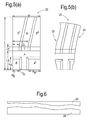
- FIG. 5 The detailed example shown in Figure 5 has been demonstrated to achieve approximately a 300g weight saving over the prior art fan blades.
- In the lowermost region A there is a region A' in one lower corner and a region A" in the opposite lower corner, and a respective transition region T A ' and T A " is provided between the region A' and A" and the remainder of the region A.
- a region B' is provided at one chordwise side and a region B" is provided at an opposite chordwise side, so as to create a central region that is angled to a chordwise direction of the membrane by an angle ⁇ .
- a respective transition region T B ' and T B " is provided between the regions B' and B" and the remainder of the region B.
- the membrane may have a spanwise length L, and the length L A of the region A may be 20 to 40 percent of the total length L, and the length L T of the region T may be 20 to 40 percent of the total length L.
- the region A' and the transition region T A ' may have a total combined length of 30 to 50 percent, for example 40 percent, of the total length L A of the region A.
- the region A' may have a width W A , equal to or less than 50 percent of the total width W of the membrane.
- the region A" and the transition region T A " may have a total combined length L TA of 30 to 50 percent, for example 40 percent, of the total length L A of the region A.
- the region A" may have a width W A" equal to or less than 50 percent of the total width W of the membrane.
- the thickness of the region A may be approximately 1.3 mm, the thickness of the region A' may be approximately 0.6mm, and the thickness of the region A" may be approximately 0.6mm.
- the angle ⁇ may be approximately 70 to 80°.
- the thickness of the region B may be approximately 0.7mm, the thickness of the region B' may be approximately 0.6mm, and the thickness of the region B" may be approximately 0.6mm.
- a membrane 20 of varying thickness may be provided by etching a membrane of uniform thickness.
- a process known as flash grinding may be used.
- flash grinding a fixture is supplied which is surface patterned according to a mirror image of the desired pattern for the membrane 20.
- a blank membrane, e.g. of uniform thickness, is overlaid on the fixture 26 and urged to conform to the patterned surface of the fixture. Whilst in place, the reverse (upper side) of the membrane is ground flat.
- the membrane 20 is typically formed to have a contoured, e.g. tapered, side and a flat or planar side. Flash grinding typically provides a tolerance of approximately 0.05mm, which is sufficient for the present disclosure.
- the fixture 26 may be metallic. However, a metallic fixture will wear and it is expensive to replace a metallic fixture. Hence, it is preferred that the fixture is formed of e.g. ice, which is quick and inexpensive to provide.
- the method of processing a fan blade preform incorporating a membrane of non-uniform thickness is generally similar to the prior art but is distinguished therefrom as discussed below, for example.
- a pair of mutually opposing panels 12, e.g. similar to the prior art panels, are provided to sandwich membrane 20.
- the inwardly facing surfaces of the mutually opposing panels 12 (and/or the membrane 20) are printed with a suitable stop-off material such as yttrium to inhibit bonding in the region of the stop-off material in the subsequent bonding step.
- the preform 10 is subject to a bonding process, for example a diffusion bonding process similar to the prior art, to form an integral fan blade preform 10 comprising at least the pair of panels 12 bonded with the membrane 20.
- a bonding process for example a diffusion bonding process similar to the prior art, to form an integral fan blade preform 10 comprising at least the pair of panels 12 bonded with the membrane 20.
- the preform 10 Prior to the bonding process, the preform 10 may be referred to as an assembly. After the bonding process, the preform 10 may be referred to as an integral preform, or a preform body.
- the integral preform is subject to a hot forming process, for example a superplastic forming process similar to the prior art, to generate the internal cavity between the panels 12 and to superplastically form the membrane into the concertina type membrane extending between the panels, e.g. as shown in Figures 2 and 4 .
- a hot forming process for example a superplastic forming process similar to the prior art
- the membrane will have a non-uniform, e.g. a tapered, thickness in one of, or both, the radial and chordwise directions.
- the integral preform 10 is typically placed in a cavity die, and is subject to suitable temperatures and pressures to inflate the preform 10 to conform it to the internal dimensions of the cavity die.
- the stop-off material is printed (patterned) to prevent bonding of the membrane with each of the panels so as to achieve the desired structure or form of the membrane 20 within the blade cavity.
- the membrane may be contoured on only one side, and planar on the other. Or, both sides of the membrane may be contoured. In any event, during the diffusion bonding process, the panels 12 conform to the membrane to form an interface suitable for the diffusion bonding process to result in the desired bond between the panels and membranes in the interface regions where the stop-off material is not provided.
- the panels 12 and the membrane 20 may be formed of titanium.
- the large area required (which may be 1-2m 2 or more) means that the membrane 20 cannot be provided thinner than 0.5mm and still readily withstand being handled and subject to processes such as hot forming processes and diffusion bonding processes. Furthermore, on such large area membranes, the manufacturing tolerances are typically approximately 0.05mm.
- a membrane may be formed such that the thickness of at least a portion of the membrane 20 tapers along its length and/or width, between a relative thicker first region and relatively thinner second region, wherein the thickness of the membrane 20 in the first region is greater than the thickness of the membrane in the second region for example by more than 10%, 15%, 20%, 25%, 30%, 35%, 40%, 45%, 50%, 55%, 60%, 65%, 70%, 75%, 80%, 85%, 90%, 95% or even 100% of the thickness in the second region.
- the region of the membrane which is proximal to the root portion of the final blade has an average thickness which is greater than the region of the membrane which is distal to the root portion of the final blade (and for example which is proximal to the tip region of the final blade).
- the average thickness of the membrane 20 which is proximal to the root portion of the final blade is greater than the average thickness of the membrane which is distal to the root portion of the final blade for example by more than 10%, 15%, 20%, 25%, 30%, 35%, 40%, 45%, 50%, 55%, 60%, 65%, 70%, 75%, 80%, 85%, 90%, 95% or even 100% of the thickness in the second region.
Landscapes
- Engineering & Computer Science (AREA)
- Mechanical Engineering (AREA)
- General Engineering & Computer Science (AREA)
- Chemical & Material Sciences (AREA)
- Materials Engineering (AREA)
- Composite Materials (AREA)
- Architecture (AREA)
- Structures Of Non-Positive Displacement Pumps (AREA)
Abstract
Description
- The present invention relates to fan blades for turbomachines. In particular, but not exclusively, it relates to improved fan blades for gas turbine engines and a method of manufacture thereof.
- Diffusion bonded-superplastically formed line core hollow titanium fan blades are known in the prior art. The current design for a preform assembly for a wide chord fan blade (WCFB) comprises two
opposing panels 2 sandwiching amembrane 3 onto which an internal core pattern is (e.g. silk-screen) printed - a general example of the preform assembly 1 is shown inFig 1(a) , and a cross section of a final fan blade based on the preform ofFig. 1(a) is shown inFig. 1(b) , the cross-section being taken at the dashed line ofFig. 1(a) (but in the final fan blade rather than the preform assembly). - The two
opposing panels 2 are typically first welded together e.g. at their edges, and the resulting assembly is diffusion bonded into a flat pack. - Then the assembly is heated through hot forming and an inert gas is injected between the two sheets, to inflate the assembly to form an internal cavity. The membrane, which is bonded to the titanium panels at the silk-printed locations, stretches by superplastic forming under the force exerted by the gas under a temperature greater than 900 degrees Celsius, typically generating a concertina type structure between the two panels in the internal cavity, as shown in
Fig. 1(b) in cross section (taken at the dashed line inFig. 1(a) ). - Once the membrane has taken its final shape, the inert gas is removed; a vacuum being created between the two
panels 2 to prevent any water contamination thanks to the pressure differential. The panels extend between a tip portion 4 and aroot portion 5, for example as indicated in the preform assembly 1 inFig. 1(a) . - The superplastic membrane, which may take the form of an arrangement of prisms, forms the internal line-core of the blade and offers a strong resistance to stress and centrifugal force. An example of a cross-section of such a blade (post-production) is shown in
Fig. 1(b) (looking from tip to root), showing the leading-edge 6 and thetrailing edge 7 of the blade. - In an aspect, the present invention aims to provide a more lightweight fan blade than the prior art. This results in a cost reduction in the manufacturing process. It also results in a more efficient turbomachine, which results in reduced energy requirements, e.g. a reduction in fuel consumption when operating the turbomachine.
- Accordingly, the present invention provides a fan blade pre-form assembly as set forth in claim 1.
- The thickness of at least a portion of the membrane tapers along its length and/or width (breadth), between a relative thicker first region and relatively thinner second region.
- Thus, the present invention provides a pre-form assembly which, when finalized according to typical subsequent processes, provides a fan blade which is more lightweight than prior art fan blades, but which retains suitable structural rigidity and/or suitable acoustic vibration characteristics.
- The thickness of the membrane in the first region is greater than the thickness of the membrane in the second region by more than 10%, e.g. by more than 25% (of the thickness in the second region).
- The panels of the preform are arranged to define a root region and a tip region of the final fan blade, and a leading edge region and a trailing edge region of the final fan blade. The membrane may extend between root and tip regions and may extend between the leading edge and trailing edge regions.
- The first region of the membrane may be located proximate the root region. The second region of the membrane may be located distal to the root region.
- The first region may extend between the root region and the tip region along a region of the membrane which is generally equidistant between the leading and trailing edges.
- The second region may extend along at least a portion of the length of the first region, for example on one side of the first region, or on each respective side of the first region.
- The first region may include a first sub-region extending along a generally central region of the membrane between the root region and the tip region; and may include a second sub-region extending laterally between the leading edge region and the trailing edge region.
- The second sub-region may be closer to the root portion than to the tip region.
- A tapered region may be provided at each border between the first and second regions. The thickness of the tapered region may be configured to provide a transition between the respectively different thicknesses of the first and second regions.
- A surface of the membrane may be substantially planar, for planar engagement with a corresponding planar surface of a panel of said panels.
- In another aspect, the present invention provides a method of manufacture of a fan blade for a turbomachine as set forth in the appended claims.
- The method may include the steps of: providing a fan blade preform according to any aspect or embodiment of the invention described herein; performing a bonding process to bond the panels and the membrane at selected regions; performing a hot forming process on the fan blade preform to provide an internal cavity across which the membrane extends.
- The bonding process may be a diffusion bonding process.
- The hot forming process may be a superplastic forming process.
- In yet another aspect, the present invention provides a fan blade for a turbomachine comprising: a pair of mutually opposing fan blade skins, arranged to extend between the leading and trailing edges of the fan blade and between the root and tip portions of the fan blade to define an internal cavity, an internal membrane spanning the cavity between the respective skins, and extending at least partway between the root and tip portions; wherein the thickness of the membrane is non-uniform.
- For example, the thickness of at least a portion of the membrane may taper along its length between the root and tip portions, from a relative thicker first region to a relatively thinner second region.
- Additionally, or alternatively, the thickness of at least a portion of the membrane may taper along its breadth spanning the cavity between the respective fan blade skins, from a relative thicker first region to a relatively thinner second region.
- The thickness of the membrane in the first region is greater than the thickness of the membrane in the second region by more than 10%, e.g. by more than 25% (of the thickness in the second region).
- Embodiments will now be described by way of example with reference to the accompanying drawings in which:
-
Figure 1(a) shows an exploded view of a fan blade preform according to the prior art; -
Figure 1(b) shows a cross section of a final fan blade based on the preform ofFigure 1(a) , the cross-section being taken at the dashed line ofFigure 1(a) in the final fan blade; -
Figure 2(a) shows an exploded view of a fan blade preform; -
Figure 2(b) shows a cross section of a final fan blade based on the preform ofFigure 2(a) , the cross-section being taken at the dashed line ofFigure 2(a) in the final fan blade; -
Figure 3(a) shows an example of a preform membrane; -
Figure 3(b) shows an example plan view of a membrane in a final blade; -
Figure 4(a) shows an exploded view of a fan blade preform; -
Figure 4(b) shows a cross section of a final fan blade based on the preform ofFigure 4(a) , the cross-section being taken at the dashed line ofFigure 4(a) in the final fan blade; -
Figure 5(a) shows an example of a preform membrane; -
Figure 5(b) shows an example plan view of a membrane in a final blade; and -
Figure 6 shows a simplified example of a method of producing a membrane of non-uniform thickness. - The present invention is particularly suited to providing improved fan blades for a turbomachine, such as a gas turbine engine.
Fig. 2(a) shows an exploded view of the basic elements of afan blade preform 10. -
Preform 10 includes a pair of mutually opposingpanels 12, which will eventually form the outer skin of the final fan blade. Thepanels 12 cooperate to provide atip portion 16 and aroot portion 14 of final fan blade. For ease of explanation, theroot portion 14 andtip portion 16 are shown inFigure 2(a) without excess, or surplus, material which may be present in thepreform 10 when being worked in practice. Indeed, in practice, surplus material is typically present, and is machined or otherwise removed following the diffusion bonding and superplastic forming steps. The presence and removal of such surplus material will be omitted here for reasons of brevity and clarity of explanation. - On their respective outer surfaces,
panels 12 may include structural features required in the final fan blade, forexample root members 18 for securing the final fan blade into the hub of the fan in which the blade is to be incorporated.Root members 18 may not be in their final form in the preform, further manufacturing steps may be required to achieve the desired final form, for example machining or other processes. -
Panels 12 of the preform 10 sandwich amembrane 20. However, unlike the prior art membranes,membrane 20 is of appreciable varying thickness. In particular, the thickness of the membrane preferably tapers. - The thickness preferably tapers along its length from the root portion of the
preform 10 to the tip portion of thepreform 10. - The taper may be present in only a portion of the length of the membrane. For example, the taper may provide a transition region between two regions of respectively different, but substantially uniform, thicknesses of the membrane. Alternatively, the entire length of the membrane between the root portion and tip portion of the
preform 10 may taper. The taper may be linear, but it may be non-linear. -
Figure 3(a) shows an example of amembrane 20, which has three distinct thickness regions.Figure 3(b) shows an example of the final form of themembrane 20 after the subsequent processing resulting in the final blade. - As can be seen from
Figure 3(a) , themembrane 20 includes three respective thickness regions A, T, B. - The lowermost region A is intended to form the
membrane 20, in the final blade cavity, relatively near to the root portion of the final blade. As an example, this region has a thickness of 1.27mm. - The upper most region B is intended to form the
membrane 20, in the final blade cavity, relatively near to the tip portion of the final blade. As an example, this region has a thickness of 0.711 mm, which is appreciably thinner than the lowermost region. - A region T of tapered thickness is shown between the lowermost and uppermost regions A, B. This region may be referred to as a taper region or a transition zone for example. The taper region provides a taper in the thickness of the membrane from the relatively thicker lowermost region, to the relatively thicker uppermost region.
- Thus, as can be seen from
Fig. 3(b) the region of the membrane which is proximal to the root portion of the final blade is thicker than the region of the membrane which is distal to the root portion of the final blade (and which is proximal to the tip region of the final blade). The taper region may be chosen to be generally in the mid-span position of the final blade. - By way of example only, the span length of the lowermost region A may be 20 to 40 percent of the total span length of the
membrane 20. The region T may have a span length of less than 20 percent (e.g. less than 10 percent) of the total span length of the membrane. By way of example only, sample dimensions are now provided but as will be appreciated by the person skilled in the art the regions and membrane may have alternative suitable dimensions. - According to this example, the region of the blade which experiences relatively large stresses and centrifugal forces includes a suitably thick (and therefore strong) membrane to help withstand the forces. Whereas the region of the blade which experiences relatively smaller stresses and centrifugal forces can be made thinner (whilst nonetheless remaining suitably thick and strong enough to withstand the forces), thereby resulting in an advantageous weight reduction.
- A more detailed example of a
preform 10 andmembrane 20 is shown inFigures 4 and5 , in which multiple taper regions are provided. - Similarly to the previous example, taper regions are provided between the
root portion 14 and thetip 16 of thepreform 10. However, in this example, taper regions are also provided in themembrane 20 in the width direction of the membrane, in other words between the respective regions of themembrane 20 which will reside near to the leading edge and near to the trailing edge of the final blade. - The leading
edge 22 and the trailingedge 24 of the final blade are shown inFigure 4(b) for example, and are also indicated inFigure 5(b) for convenience of reference. - Accordingly, a fan blade may include an internal membrane in the blade cavity, which varies in thickness in at least one of, but preferably both, the radial and chord-wise directions of the final blade.
- Therefore, the regions of the membrane which are likely to experience in use relatively larger stresses and forces (than other regions) can be made relatively thicker than regions which experience in use relatively smaller (weaker) stresses and forces.
- The detailed example shown in
Figure 5 has been demonstrated to achieve approximately a 300g weight saving over the prior art fan blades. In the example shown inFigure 5 , there are multiple regions of differing thickness and multiple transition regions. Similar to the previously described example, there is a lowermost region A, an uppermost region B and a transition region T between the lowermost and uppermost regions. In the lowermost region A, there is a region A' in one lower corner and a region A" in the opposite lower corner, and a respective transition region TA' and TA" is provided between the region A' and A" and the remainder of the region A. In the uppermost region B a region B' is provided at one chordwise side and a region B" is provided at an opposite chordwise side, so as to create a central region that is angled to a chordwise direction of the membrane by an angle α. A respective transition region TB' and TB" is provided between the regions B' and B" and the remainder of the region B. - By way of example only the dimensions for the membrane are provided, but it is understood by the person skilled in the art that these dimensions are example dimensions. The membrane may have a spanwise length L, and the length LA of the region A may be 20 to 40 percent of the total length L, and the length LT of the region T may be 20 to 40 percent of the total length L. The region A' and the transition region TA' may have a total combined length of 30 to 50 percent, for example 40 percent, of the total length LA of the region A. The region A' may have a width WA, equal to or less than 50 percent of the total width W of the membrane. The region A" and the transition region TA" may have a total combined length LTA of 30 to 50 percent, for example 40 percent, of the total length LA of the region A. The region A" may have a width WA" equal to or less than 50 percent of the total width W of the membrane. The thickness of the region A may be approximately 1.3 mm, the thickness of the region A' may be approximately 0.6mm, and the thickness of the region A" may be approximately 0.6mm. The angle α may be approximately 70 to 80°. The thickness of the region B may be approximately 0.7mm, the thickness of the region B' may be approximately 0.6mm, and the thickness of the region B" may be approximately 0.6mm.
- A
membrane 20 of varying thickness may be provided by etching a membrane of uniform thickness. Alternatively, a process known as flash grinding may be used. In flash grinding a fixture is supplied which is surface patterned according to a mirror image of the desired pattern for themembrane 20. A blank membrane, e.g. of uniform thickness, is overlaid on thefixture 26 and urged to conform to the patterned surface of the fixture. Whilst in place, the reverse (upper side) of the membrane is ground flat. - Thus, the
membrane 20 is typically formed to have a contoured, e.g. tapered, side and a flat or planar side. Flash grinding typically provides a tolerance of approximately 0.05mm, which is sufficient for the present disclosure. - The
fixture 26 may be metallic. However, a metallic fixture will wear and it is expensive to replace a metallic fixture. Hence, it is preferred that the fixture is formed of e.g. ice, which is quick and inexpensive to provide. - The method of processing a fan blade preform incorporating a membrane of non-uniform thickness is generally similar to the prior art but is distinguished therefrom as discussed below, for example.
- In general, a pair of mutually opposing
panels 12, e.g. similar to the prior art panels, are provided tosandwich membrane 20. - The inwardly facing surfaces of the mutually opposing panels 12 (and/or the membrane 20) are printed with a suitable stop-off material such as yttrium to inhibit bonding in the region of the stop-off material in the subsequent bonding step.
- The
preform 10 is subject to a bonding process, for example a diffusion bonding process similar to the prior art, to form an integralfan blade preform 10 comprising at least the pair ofpanels 12 bonded with themembrane 20. Prior to the bonding process, thepreform 10 may be referred to as an assembly. After the bonding process, thepreform 10 may be referred to as an integral preform, or a preform body. - Subsequently, the integral preform is subject to a hot forming process, for example a superplastic forming process similar to the prior art, to generate the internal cavity between the
panels 12 and to superplastically form the membrane into the concertina type membrane extending between the panels, e.g. as shown inFigures 2 and4 . However, the membrane will have a non-uniform, e.g. a tapered, thickness in one of, or both, the radial and chordwise directions. - In the hot forming process, the
integral preform 10 is typically placed in a cavity die, and is subject to suitable temperatures and pressures to inflate thepreform 10 to conform it to the internal dimensions of the cavity die. - Similarly to the prior art, the stop-off material is printed (patterned) to prevent bonding of the membrane with each of the panels so as to achieve the desired structure or form of the
membrane 20 within the blade cavity. - The membrane may be contoured on only one side, and planar on the other. Or, both sides of the membrane may be contoured. In any event, during the diffusion bonding process, the
panels 12 conform to the membrane to form an interface suitable for the diffusion bonding process to result in the desired bond between the panels and membranes in the interface regions where the stop-off material is not provided. - The
panels 12 and themembrane 20 may be formed of titanium. - Where the membrane is formed of titanium, the large area required (which may be 1-2m2 or more) means that the
membrane 20 cannot be provided thinner than 0.5mm and still readily withstand being handled and subject to processes such as hot forming processes and diffusion bonding processes. Furthermore, on such large area membranes, the manufacturing tolerances are typically approximately 0.05mm. - However, a membrane may be formed such that the thickness of at least a portion of the
membrane 20 tapers along its length and/or width, between a relative thicker first region and relatively thinner second region, wherein the thickness of themembrane 20 in the first region is greater than the thickness of the membrane in the second region for example by more than 10%, 15%, 20%, 25%, 30%, 35%, 40%, 45%, 50%, 55%, 60%, 65%, 70%, 75%, 80%, 85%, 90%, 95% or even 100% of the thickness in the second region. - In particular, the region of the membrane which is proximal to the root portion of the final blade has an average thickness which is greater than the region of the membrane which is distal to the root portion of the final blade (and for example which is proximal to the tip region of the final blade). The average thickness of the
membrane 20 which is proximal to the root portion of the final blade is greater than the average thickness of the membrane which is distal to the root portion of the final blade for example by more than 10%, 15%, 20%, 25%, 30%, 35%, 40%, 45%, 50%, 55%, 60%, 65%, 70%, 75%, 80%, 85%, 90%, 95% or even 100% of the thickness in the second region.
Claims (15)
- A turbomachine fan blade preform (10) comprising:a pair of mutually opposing panels (12); anda membrane (20) sandwiched between the pair of panels (12);wherein the thickness of at least a portion of the membrane (20) tapers along its length and/or width, between a relatively thicker first region and relatively thinner second region.
- A turbomachine fan blade preform according to claim 1 wherein the thickness of the membrane (20) in the first region is greater than the thickness of the membrane in the second region by more than 10% of the thickness in the second region.
- A turbomachine fan blade preform according to claim 1 wherein the thickness of the membrane (20) in the first region is greater than the thickness of the membrane in the second region by more than 25% of the thickness in the second region.
- A turbomachine fan blade preform according to any one of claims 1 to 3 wherein the panels (12) of the preform are arranged to define a root region (14) and a tip region (16) of the final fan blade, and a leading edge region (22) and a trailing edge region (24) of the final fan blade; and wherein the membrane (20) extends between root and tip regions (14, 16) and between the leading edge and trailing edge regions (14, 16).
- A turbomachine fan blade preform according to claim 4 wherein the first region of the membrane (20) is located proximate the root region (14), and wherein the second region of the membrane (20) is located distal to the root region (14).
- A turbomachine fan blade preform according to claim 4 wherein the first region extends between the root region (4) and the tip region (16) along a region of the membrane (20) which is generally equidistant between the leading and trailing edges (22, 24).
- A turbomachine fan blade preform according to claim 6 wherein the second region extends along at least a portion of the length of the first region, on each respective side of the first region.
- A turbomachine fan blade preform according to claim 6 or 7 wherein the first region includes a first sub-region extending along a generally central region of the membrane (20) between the root region (14) and the tip region, and a second sub-region extending laterally between the leading edge region (22) and the trailing edge region (24).
- A turbomachine fan blade preform according to claim 8 wherein the second sub-region is closer to the root portion (14) than to the tip region (16).
- A turbomachine fan blade preform according to any one of the preceding claims further including a tapered region provided at each border between the first and second regions, the thickness of the tapered region being configured to provide a transition between the respectively different thicknesses of the first and second regions.
- A turbomachine fan blade preform according to any one of the preceding claims wherein a surface of the membrane (20) is substantially planar, for planar engagement with a corresponding planar surface of a panel of said panels.
- A method of manufacture of a turbomachine fan blade, the method including the steps of:providing a fan blade preform according to any one of claims 1 to 11;performing a bonding process to bond the panels and the membrane at selected regions;performing a hot forming process on the fan blade preform to provide an internal cavity across which the membrane extends.
- A method according to claim 12, wherein the bonding process is a diffusion bonding process.
- A method according to claim 12 or 13, wherein the hot forming process is a superplastic forming process.
- A turbomachine fan blade comprising
a pair of mutually opposing fan blade skins (12), arranged to extend between the leading (22) and trailing (24) edges of the fan blade and between the root (14) and tip (16) portions of the fan blade (10) to define an internal cavity, and
an internal membrane (20) spanning the cavity between the respective skins, and extending at least partway between the root (14) and tip (16) portions;
wherein the thickness of at least a portion of the membrane (20) tapers along its length between the root (14) and tip (16) portions, from a relative thicker first region to a relatively thinner second region.
Applications Claiming Priority (1)
| Application Number | Priority Date | Filing Date | Title |
|---|---|---|---|
| GBGB1500605.9A GB201500605D0 (en) | 2015-01-15 | 2015-01-15 | Fan blade |
Publications (1)
| Publication Number | Publication Date |
|---|---|
| EP3048252A1 true EP3048252A1 (en) | 2016-07-27 |
Family
ID=52597607
Family Applications (1)
| Application Number | Title | Priority Date | Filing Date |
|---|---|---|---|
| EP15200478.4A Withdrawn EP3048252A1 (en) | 2015-01-15 | 2015-12-16 | Fan blade |
Country Status (3)
| Country | Link |
|---|---|
| US (1) | US10247008B2 (en) |
| EP (1) | EP3048252A1 (en) |
| GB (1) | GB201500605D0 (en) |
Families Citing this family (1)
| Publication number | Priority date | Publication date | Assignee | Title |
|---|---|---|---|---|
| FR3087699B1 (en) * | 2018-10-30 | 2021-11-26 | Safran Aircraft Engines | HYBRIDIZATION OF THE FIBERS OF THE FIBER REINFORCEMENT OF A DAWN |
Citations (4)
| Publication number | Priority date | Publication date | Assignee | Title |
|---|---|---|---|---|
| EP2014384A1 (en) * | 2007-07-13 | 2009-01-14 | Rolls-Royce plc | Component with internal damping and method for manufacturing the same |
| EP2014386A1 (en) * | 2007-07-13 | 2009-01-14 | Rolls-Royce plc | A component with a damping filler |
| EP2233239A2 (en) * | 2009-03-18 | 2010-09-29 | Rolls-Royce Plc | A method of manufacturing a component comprising an internal structure |
| EP2273069A2 (en) * | 2009-07-02 | 2011-01-12 | Rolls-Royce plc | A method of forming an internal structure within a hollow component |
Family Cites Families (5)
| Publication number | Priority date | Publication date | Assignee | Title |
|---|---|---|---|---|
| IT1176673B (en) * | 1983-09-23 | 1987-08-18 | Gen Electric | QUARRY SHOVEL FOR TURBOMACHINE |
| US5253419A (en) * | 1991-02-20 | 1993-10-19 | Societe Nationale D'etude Et De Construction De Moteurs D'aviation "S.N.E.C.M.A." | Method of manufacturing a hollow blade for a turboshaft engine |
| FR2698126B1 (en) | 1992-11-18 | 1994-12-16 | Snecma | Hollow fan blade or turbomachine compressor. |
| GB0709838D0 (en) | 2007-05-23 | 2007-07-04 | Rolls Royce Plc | A hollow blade and a method of manufacturing a hollow blade |
| US8662855B2 (en) | 2010-08-31 | 2014-03-04 | United Technologies Corporation | Integrally woven composite fan blade using progressively larger weft yarns |
-
2015
- 2015-01-15 GB GBGB1500605.9A patent/GB201500605D0/en not_active Ceased
- 2015-12-16 EP EP15200478.4A patent/EP3048252A1/en not_active Withdrawn
- 2015-12-16 US US14/971,198 patent/US10247008B2/en not_active Expired - Fee Related
Patent Citations (4)
| Publication number | Priority date | Publication date | Assignee | Title |
|---|---|---|---|---|
| EP2014384A1 (en) * | 2007-07-13 | 2009-01-14 | Rolls-Royce plc | Component with internal damping and method for manufacturing the same |
| EP2014386A1 (en) * | 2007-07-13 | 2009-01-14 | Rolls-Royce plc | A component with a damping filler |
| EP2233239A2 (en) * | 2009-03-18 | 2010-09-29 | Rolls-Royce Plc | A method of manufacturing a component comprising an internal structure |
| EP2273069A2 (en) * | 2009-07-02 | 2011-01-12 | Rolls-Royce plc | A method of forming an internal structure within a hollow component |
Also Published As
| Publication number | Publication date |
|---|---|
| US20160208617A1 (en) | 2016-07-21 |
| GB201500605D0 (en) | 2015-02-25 |
| US10247008B2 (en) | 2019-04-02 |
Similar Documents
| Publication | Publication Date | Title |
|---|---|---|
| US11602809B2 (en) | Processes and tooling associated with diffusion bonding the periphery of a cavity-back airfoil | |
| US5469618A (en) | Method for manufacturing hollow airfoils (two-piece concept) | |
| US5711068A (en) | Method of manufacturing a blade | |
| US5243758A (en) | Design and processing method for manufacturing hollow airfoils (three-piece concept) | |
| US9328614B2 (en) | Method of making a metal reinforcing piece | |
| US9321100B2 (en) | Method for producing a metal reinforcement for a turbomachine blade | |
| EP3434867B1 (en) | Processes and tooling associated with diffusion bonding | |
| US10787914B2 (en) | CMC airfoil with monolithic ceramic core | |
| EP2226133B1 (en) | Method of manufacturing an aerofoil | |
| EP1081333A2 (en) | Plastically formed hybrid airfoil | |
| RU2607389C2 (en) | Method of metal part producing | |
| US7896221B2 (en) | Method of manufacturing an aerofoil | |
| US10247008B2 (en) | Fan blade | |
| US8496440B2 (en) | Method of manufacturing an aerofoil | |
| EP3067153A1 (en) | Manufacture of a hollow aerofoil | |
| EP1605135B1 (en) | Method of making and joining an aerofoil and root | |
| US9956653B2 (en) | Method of making an aerofoil cladding body |
Legal Events
| Date | Code | Title | Description |
|---|---|---|---|
| PUAI | Public reference made under article 153(3) epc to a published international application that has entered the european phase |
Free format text: ORIGINAL CODE: 0009012 |
|
| AK | Designated contracting states |
Kind code of ref document: A1 Designated state(s): AL AT BE BG CH CY CZ DE DK EE ES FI FR GB GR HR HU IE IS IT LI LT LU LV MC MK MT NL NO PL PT RO RS SE SI SK SM TR |
|
| AX | Request for extension of the european patent |
Extension state: BA ME |
|
| STAA | Information on the status of an ep patent application or granted ep patent |
Free format text: STATUS: REQUEST FOR EXAMINATION WAS MADE |
|
| 17P | Request for examination filed |
Effective date: 20170125 |
|
| RBV | Designated contracting states (corrected) |
Designated state(s): AL AT BE BG CH CY CZ DE DK EE ES FI FR GB GR HR HU IE IS IT LI LT LU LV MC MK MT NL NO PL PT RO RS SE SI SK SM TR |
|
| RAP1 | Party data changed (applicant data changed or rights of an application transferred) |
Owner name: ROLLS-ROYCE PLC |
|
| STAA | Information on the status of an ep patent application or granted ep patent |
Free format text: STATUS: THE APPLICATION HAS BEEN WITHDRAWN |
|
| 18W | Application withdrawn |
Effective date: 20200605 |