EP3048207A1 - Flush valve assembly and toilet flush system incorporating the same - Google Patents
Flush valve assembly and toilet flush system incorporating the same Download PDFInfo
- Publication number
- EP3048207A1 EP3048207A1 EP16150690.2A EP16150690A EP3048207A1 EP 3048207 A1 EP3048207 A1 EP 3048207A1 EP 16150690 A EP16150690 A EP 16150690A EP 3048207 A1 EP3048207 A1 EP 3048207A1
- Authority
- EP
- European Patent Office
- Prior art keywords
- water
- valve
- flush
- chamber
- valve member
- Prior art date
- Legal status (The legal status is an assumption and is not a legal conclusion. Google has not performed a legal analysis and makes no representation as to the accuracy of the status listed.)
- Withdrawn
Links
- XLYOFNOQVPJJNP-UHFFFAOYSA-N water Substances O XLYOFNOQVPJJNP-UHFFFAOYSA-N 0.000 claims abstract description 94
- 238000007599 discharging Methods 0.000 claims abstract description 9
- 230000007246 mechanism Effects 0.000 claims abstract description 8
- 238000007789 sealing Methods 0.000 claims abstract description 7
- 230000009471 action Effects 0.000 claims description 17
- 230000000630 rising effect Effects 0.000 claims description 4
- 230000007704 transition Effects 0.000 claims description 4
- 230000004044 response Effects 0.000 claims description 3
- 238000011010 flushing procedure Methods 0.000 description 11
- 238000009434 installation Methods 0.000 description 2
- 230000002093 peripheral effect Effects 0.000 description 2
- 230000004075 alteration Effects 0.000 description 1
- 238000010276 construction Methods 0.000 description 1
- 230000003111 delayed effect Effects 0.000 description 1
- 230000007613 environmental effect Effects 0.000 description 1
- 230000004048 modification Effects 0.000 description 1
- 238000012986 modification Methods 0.000 description 1
- 125000006850 spacer group Chemical group 0.000 description 1
- 230000001960 triggered effect Effects 0.000 description 1
Images







Classifications
-
- E—FIXED CONSTRUCTIONS
- E03—WATER SUPPLY; SEWERAGE
- E03D—WATER-CLOSETS OR URINALS WITH FLUSHING DEVICES; FLUSHING VALVES THEREFOR
- E03D1/00—Water flushing devices with cisterns ; Setting up a range of flushing devices or water-closets; Combinations of several flushing devices
- E03D1/30—Valves for high or low level cisterns; Their arrangement ; Flushing mechanisms in the cistern, optionally with provisions for a pre-or a post- flushing and for cutting off the flushing mechanism in case of leakage
- E03D1/34—Flushing valves for outlets; Arrangement of outlet valves
-
- E—FIXED CONSTRUCTIONS
- E03—WATER SUPPLY; SEWERAGE
- E03D—WATER-CLOSETS OR URINALS WITH FLUSHING DEVICES; FLUSHING VALVES THEREFOR
- E03D1/00—Water flushing devices with cisterns ; Setting up a range of flushing devices or water-closets; Combinations of several flushing devices
- E03D1/30—Valves for high or low level cisterns; Their arrangement ; Flushing mechanisms in the cistern, optionally with provisions for a pre-or a post- flushing and for cutting off the flushing mechanism in case of leakage
- E03D1/34—Flushing valves for outlets; Arrangement of outlet valves
- E03D1/35—Flushing valves having buoyancy
-
- E—FIXED CONSTRUCTIONS
- E03—WATER SUPPLY; SEWERAGE
- E03D—WATER-CLOSETS OR URINALS WITH FLUSHING DEVICES; FLUSHING VALVES THEREFOR
- E03D5/00—Special constructions of flushing devices, e.g. closed flushing system
- E03D5/01—Special constructions of flushing devices, e.g. closed flushing system using flushing pumps
-
- E—FIXED CONSTRUCTIONS
- E03—WATER SUPPLY; SEWERAGE
- E03D—WATER-CLOSETS OR URINALS WITH FLUSHING DEVICES; FLUSHING VALVES THEREFOR
- E03D5/00—Special constructions of flushing devices, e.g. closed flushing system
- E03D5/02—Special constructions of flushing devices, e.g. closed flushing system operated mechanically or hydraulically (or pneumatically) also details such as push buttons, levers and pull-card therefor
- E03D5/024—Operated hydraulically or pneumatically
-
- E—FIXED CONSTRUCTIONS
- E03—WATER SUPPLY; SEWERAGE
- E03D—WATER-CLOSETS OR URINALS WITH FLUSHING DEVICES; FLUSHING VALVES THEREFOR
- E03D5/00—Special constructions of flushing devices, e.g. closed flushing system
- E03D5/02—Special constructions of flushing devices, e.g. closed flushing system operated mechanically or hydraulically (or pneumatically) also details such as push buttons, levers and pull-card therefor
- E03D5/09—Special constructions of flushing devices, e.g. closed flushing system operated mechanically or hydraulically (or pneumatically) also details such as push buttons, levers and pull-card therefor directly by the hand
-
- E—FIXED CONSTRUCTIONS
- E03—WATER SUPPLY; SEWERAGE
- E03D—WATER-CLOSETS OR URINALS WITH FLUSHING DEVICES; FLUSHING VALVES THEREFOR
- E03D5/00—Special constructions of flushing devices, e.g. closed flushing system
- E03D5/10—Special constructions of flushing devices, e.g. closed flushing system operated electrically, e.g. by a photo-cell; also combined with devices for opening or closing shutters in the bowl outlet and/or with devices for raising/or lowering seat and cover and/or for swiveling the bowl
-
- E—FIXED CONSTRUCTIONS
- E03—WATER SUPPLY; SEWERAGE
- E03D—WATER-CLOSETS OR URINALS WITH FLUSHING DEVICES; FLUSHING VALVES THEREFOR
- E03D5/00—Special constructions of flushing devices, e.g. closed flushing system
- E03D5/10—Special constructions of flushing devices, e.g. closed flushing system operated electrically, e.g. by a photo-cell; also combined with devices for opening or closing shutters in the bowl outlet and/or with devices for raising/or lowering seat and cover and/or for swiveling the bowl
- E03D5/105—Special constructions of flushing devices, e.g. closed flushing system operated electrically, e.g. by a photo-cell; also combined with devices for opening or closing shutters in the bowl outlet and/or with devices for raising/or lowering seat and cover and/or for swiveling the bowl touchless, e.g. using sensors
-
- Y—GENERAL TAGGING OF NEW TECHNOLOGICAL DEVELOPMENTS; GENERAL TAGGING OF CROSS-SECTIONAL TECHNOLOGIES SPANNING OVER SEVERAL SECTIONS OF THE IPC; TECHNICAL SUBJECTS COVERED BY FORMER USPC CROSS-REFERENCE ART COLLECTIONS [XRACs] AND DIGESTS
- Y02—TECHNOLOGIES OR APPLICATIONS FOR MITIGATION OR ADAPTATION AGAINST CLIMATE CHANGE
- Y02A—TECHNOLOGIES FOR ADAPTATION TO CLIMATE CHANGE
- Y02A20/00—Water conservation; Efficient water supply; Efficient water use
- Y02A20/40—Protecting water resources
Definitions
- the present invention relates to a flush valve assembly and a toilet flush system incorporating the same.
- the invention seeks to mitigate or to at least alleviate one or more of such problems and/or shortcomings by providing a new or otherwise improved flush valve assembly and toilet flush system incorporating the same.
- a flush valve assembly for use in a toilet tank having at its bottom a drain opening.
- the flush valve assembly comprises a valve seat provided at or by said drain opening, and a valve member movable relative to the valve seat and having a valve part for, in a lower position, sealing engagement with the valve seat to hold water in said toilet tank and, in an upper position, disengagement from the valve seat to drain water from said toilet tank.
- the valve member includes an internal chamber for containing water to reduce buoyancy of the valve member in water, so that the valve member may descend through water to reach the valve seat for sealing engagement therewith.
- the valve member also has an inlet for admitting water into the chamber, and an outlet for discharging water from the chamber.
- the inlet and outlet are provided at upper and lower parts of the chamber respectively;
- the chamber includes an internal passage for discharging water from the chamber, which passage has first and second ends and extends upwardly from its first end and then downwardly to its second end through, and acting as, the outlet of the chamber.
- At least the first end of the first and second ends of the passage is located at a lowermost part of the chamber
- the passage has a first section extending upwardly and a second section which extends downwardly and within and along the length of the first section.
- the passage includes a relatively short transition between the first and second sections
- the passage comprises an auto-syphon passage for discharging water from the chamber by syphon action automatically upon water in the chamber rising above the passage.
- the chamber includes a vent in communication with the ambient atmosphere.
- vent and the inlet are provided at an upper end of the valve member.
- the flush valve assembly includes a guide in engagement with the valve member for guiding the valve member to move upwardly and downwardly.
- the guide is in sliding engagement with the valve member
- a toilet flush system comprising a toilet tank, a tank refill mechanism for refilling the toilet tank with water, an aforesaid flush valve assembly used in the toilet tank, and an operating unit for operating the flush valve assembly.
- the operating unit includes a valve in a water circuit from a water source to the inlet of the valve member of the flush valve assembly for controlling supply of water into the chamber;
- the operating unit includes an actuator for lifting the valve member from the valve seat.
- the actuator comprises a liquid-operated actuator
- the operating unit includes a valve device for controlling supply of water to operate the actuator
- the toilet flush system 20 includes a toilet tank 200 which has at its bottom a drain opening 201.
- the flush valve assembly 10 is formed by a valve seat 110 provided at (or by) the drain opening 201, and a valve member 100 which is movable relative to the valve seat 110, together acting as a flush valve.
- the flush valve assembly 10 includes a generally cylindrical hollow structure 120 within which the valve member 100 is held captive, acting as a guide in sliding engagement with the valve member 100 for guiding it to move vertically upward and downward.
- the valve seat 110 is a generally cylindrical member which has a lower end 111 inserted through the drain opening 201 and then secured by an external screw-threaded collar 112, and an upper end 113 having a annularly ribbed uppermost surface 114 for valve closing engagement with the valve member 100 above it.
- the valve member 100 has a generally cylindrical hollow body that points downwards and within which an internal chamber 130 is defined for filling with water for operation.
- the valve member 100 has a pointed (or flat) lower end 101 and a flat upper end 102, and is fitted 360° around its periphery i.e. cylindrical peripheral wall with a flat rubber ring 103 that acts a valve member for cooperation with the uppermost surface 114 of the valve seat 110 to perform valve closing and opening actions.
- the guide structure 120 sits co-axially on and is integrally connected to the valve seat 110 by means of several, for example four, integral legs 121, such that the guide structure 120 is fixed to the drain opening 201.
- the valve member 100 which fits inside the guide structure 120, has four vertical channels 104 on and around its peripheral wall within which respective protrusions on the inner surface of the guide structure 120 slidably engage such that the valve member 100 is guided to slide vertically upwards and downwards relative to the guide structure 120.
- valve member 100 While being slidable upwards and downwards relative to the guide structure 120, the valve member 100 has its rubber ring 103 arranged for, in a lower position (see e.g. Figure 8 ), sealing engagement with the uppermost surface 114 of the valve seat 110 to hold water in the toilet tank 200 and, in an upper position (see e.g. Figure 10 ), dis-engagement from the uppermost surface 114 of the valve seat 110 to drain water from the toilet tank 200.
- the valve member 100 is designed to operate with its internal chamber 130 arranged to contain water for reducing the buoyancy of the valve member 100 in water, so that the valve member 100 may descend through water, before the toilet tank 200 is completely drained, to reach the valve seat 110 for sealing engagement therewith.
- the valve member 100 includes an inlet 131 for admitting water into the chamber 130 and an outlet 132 for discharging water from the chamber 130.
- the inlet 131 and outlet 132 are provided at upper and lower parts of the chamber 130 respectively and, more specifically, the corresponding upper and lower ends 102 and 101 of the valve member 100.
- the chamber 130 includes a vent 133 for pressure balancing, which is also provided at the upper end 102 of the valve member 100.
- the inlet 131 and vent 133 are connected with respective upright rigid pipes 131P and 133P.
- the inlet pipe 131P is connected by means of a flexible tube 33 to a water source (i.e. the flush water supply).
- the vent pipe 133P has its upper end left open to the ambient atmosphere, extending to a height beyond the highest level of the water in the toilet tank 200 can get to.
- the chamber 130 includes an internal passage Q (i.e. Q1+Q2+Q3) for discharging water from within the chamber 130.
- the passage Q has first end Q1 and second end Q2 and extends upwardly from its first end Q1 and then downwardly to its second end Q2 through, and acting as, the outlet 132 of the chamber 130.
- At least the first end Q1 of the first and second ends Q1 and Q2 of the passage Q is located at a lowermost part 101 (i.e. the lower end 101) of the chamber 130.
- the passage Q should have its first end Q1 located practically at the lowest possible position in the chamber 130.
- both of the first and second ends Q1 and Q2 of the passage Q are located at or near the lowermost part 101 of the chamber 130.
- the passage Q acts as a syphon passage which serves to discharge water from within the chamber 130 by syphon action automatically upon the water in the chamber 130 rising over the passage Q, i.e. above the uppermost end or position (Q3) of the passage Q.
- the passage Q turns from extending upward to extending downward at a position Q3, which is the passage's uppermost position, near an uppermost part 102 (i.e. the upper end 102) of the chamber 130.
- the passage Q extends upwardly and downwardly, both vertically and in a substantially linear manner.
- the siphon passage Q is formed by a pair of vertical outer and inner tubes T1 and T2, with the outer tube T1 extending co-axially outside and along the inner tube T2.
- the inner tube T2 is open at both of its opposite upper and lower ends, and extends vertically through the outlet 132 of the chamber 130.
- the inner tube T2 is integrally connected with the rim of the outlet 132 such that it is erected centrally and mainly inside the chamber 130, with a relatively short lowermost section projecting downwardly from the lower end 101 of the valve member 100.
- the outer tube T1 has a closed upper end which encloses the open upper end of the inner tube T2 and is connected thereto by means of spacers (not shown), such that the outer tube T1 is wholly supported by the inner tube T2.
- the outer tube T1 is of about the same length as the main section of the inner tube T2 inside the chamber 130.
- the siphon passage Q has two, first and second sections which are provided by the outer and inner tubes T1 and T2 respectively, with the first section extending between the outer and inner tubes T1 and T2 and the second section extending within the inner tube T2.
- the first section extends upwardly, and the second section extends downwardly and within and along the length of the first section.
- the siphon passage Q has a relatively short transition G between the first and second sections, which is the gap between the upper ends of the outer and inner tubes T1 and T2 measured along their length. This transition G or gap should not be too long to avoid excess air trapped in the siphon passage Q, which otherwise would hinder the establishment of a siphon flow.
- the toilet flush system 20 further includes a tank refill mechanism 300 for refilling the toilet tank 200 with water, and an operating unit 400 for operating, or controlling the operation of, the flush valve assembly 10.
- the tank refill mechanism 300 has a generally known construction, including a water inlet tube 310 which extends upright through the bottom at a rear corner of the toilet tank 200, a normally-open valve 320 located at the uppermost end of the inlet tube 310, and a float 330 slidably mounted on the inlet tube 310.
- a tee fitting 312 at the bottom of the inlet tube 310 inside the toilet tank 200 supplies water to the operating unit 400 via a flexible tube 31.
- Water is fed into the inlet tube 310 via a lowermost end 311 thereof, situated immediately underneath the toilet tank 200.
- the water travels up along the inlet tube 310 and is then discharged via the valve 320 into the toilet tank 200.
- the valve 320 will automatically be closed by, for example, a linkage which is operated by the float 330, upon the float 330 rising with the water to a predetermined level.
- the operation of the flush valve assembly 10 involves, at least, valve opening to trigger a flushing action, valve closing to terminate the flushing action, and flush duration control to determine the flush volume.
- the operating unit 400 includes a pair of valves (or referred to as valve devices) 410 and 420, each of which is operated by an electrical solenoid and is generally known as a solenoid valve.
- Each solenoid valve 410/420 includes a normally-closed valve (see e.g. valve member 421 in Figure 3 ) and a solenoid (e.g. designated as 422 in Figure 3 ) for opening the valve for as long as it is being energized by an electrical current.
- the solenoid valves 410 and 420 have their inlets both connected to the tube 31 for supply of water via the inlet tube 310 and their outlets connected to the liquid-operates actuator 430 and the valve member 100 respectively by means of the tubes 32 and 33.
- the first solenoid valve 410 controls the supply of water to and hence operates the actuator 430.
- the second solenoid valve 420 controls the supply of water to and hence operates, or reconditions, the valve member 100.
- the operating unit 400 includes the valve 420 in a water circuit, which includes the tubes 31 and 33, from a water source (i.e. the mains flush water source) to the inlet 131 of the valve member 100 of the flush valve assembly 10 for controlling supply of water into the chamber 130.
- a water source i.e. the mains flush water source
- the operating unit 400 includes an actuator 430 for lifting the valve member 100 from the valve seat 110 in order to trigger a flushing action.
- the actuator 430 is a liquid-operated actuator which has an internal piston-in-cylinder mechanism, an inlet 432 connected to the tube 32 for supply of water into the cylinder (of the piston-in-cylinder mechanism) of the first solenoid valve 410, and an output shaft 434 coupled with the piston (of the piston-in-cylinder mechanism) for rotation thereby upon the supply of water into the cylinder.
- the actuator 430 converts the pressure of the mains flush water into a mechanical force which then rotates the shaft 434 and hence a first link 436, which is secured at one end to the shaft 434, and in turn pulls up, by means of a second link 438, the valve member 100 from the valve seat 110 to let the water in the toilet tank 200 flush down into the toilet.
- the operating unit 400 has a number of operating modes, e.g. normal, economic (ECO) and extended modes.
- the operating unit 400 commences a flushing action upon receipt of a control signal which is provided directly or indirectly from a user via a trigger 408 ( Figure 3 ) as part of the operating unit 400.
- the trigger 408 may be a pressure, photoelectric or infrared sensor or any other suitable passive sensors, or a contact (e.g. capacitive) sensor or simply a mechanical switch or any other suitable active sensors.
- the operating unit 400 momentarily (e.g. 100ms as a ballpark figure) opens the first solenoid valve 410 ( Figure 9 ) to let the flush water pressure operate the actuator 430 to lift the valve member 100 from the valve seat 110 (from Figures 8 to 10 ).
- the valve member 100 floats on the water in the toilet tank 200 while the water is being discharged.
- the water lowers to a sufficiently low level, it will allow the valve member 100 to re-engage with the valve seat 110, whereupon the flush valve assembly 10 closes to terminate the flushing action.
- nearly the full tank of water will be discharged.
- the operating unit 400 opens the second solenoid valve 420 to fill the chamber 130 in the valve member 100 with water that is supplied via the tube 33 ( Figure 11 ).
- the valve member 100 will be filled up with water (i.e. in its valve chamber 130) very quickly and then descend through the water left in the tank 200, as it has already lost its buoyance due to the presence of water in it.
- the valve member 100 will swiftly re-engage with the valve seat 110 ( Figure 12 ), whereupon the flush valve assembly 10 closes to terminate the flushing action.
- the solenoid valve 420 Prior to, during and until completion of the descending of the valve member 100, the solenoid valve 420 will be kept open to continue filling the valve chamber 130 with water. When the water in the valve chamber 130 rises above the uppermost end of the siphon passage Q, excessive water will overflow and be discharged via the siphon passage Q and then the chamber's outlet 132, and also the valve seat 110 and the drain opening 201, into the toilet below. In practice, as water is being refilled at a higher rate than it overflows, the chamber 130 will be kept fully filled with water ( Figures 11 and 12 ).
- the operating unit 400 will keep the solenoid valve 420 open until the valve member 100 re-engages with the valve seat 110 ( Figure 12 ), to ensure that the valve member 100 will remain fully filled with water, despite losing water by overflowing, such that it will descend (i.e. not buoyant) and close upon the valve seat 110 to terminate the flushing action.
- the operating unit 400 enables a larger flush volume than normal, in that more than the full tank of water in the toilet tank 200 can be discharged by way of delayed closing of the flush valve assembly 10. This is achieved by way of continuous energization of the first solenoid valve 410, which then lifts and maintains the valve member 100 in a raised position for an extended time period, e.g. up to say 4 to 6 seconds. For as long as the valve member 100 is being hung, the water pre-stored in toilet tank 200 and then subsequently water replenishing from the inlet tube 310 via the valve 320 will be let down into the toilet.
- the operating unit 400 further includes an electronic control circuit 401 which is housed in a case 402 hung internally on the rim of the toilet tank 200 and is powered by a set of battery cells 403.
- the control circuit 401 is provided by an MCU 404 for implementing control over the operation of the other functional modules which are a timer circuit 405, a driver circuit 406, a trigger circuit 407 and any other appropriate modules.
- the timer circuit 405 is controllable and/or user-programmable to set the aforesaid predetermined time delay and extended time period for the corresponding modes of operation as described above, and any or all other time periods as are necessary for the operation. In the extended mode of operation, the timer 405 determines the duration of operation of the actuator 430 lifting the valve member 100 off the valve seat 110, thereby determining the flush volume in one or more quantities.
- the driver circuit 406 is operable to operate, i.e. energize (open) and de-energize (close), the solenoid valves 410 and 420.
- the trigger circuit 407 it is designed to trigger a flushing action as described above upon receipt of a control signal from an aforesaid passive sensor 408 detecting a certain user condition such as, in particular, when a user leaves the toilet seat. In response, the sensor generates and provides a control signal to the trigger circuit 407, either directly or via the MCU 404, to operate the actuator 430.
- the sensor 408 may alternatively be, or additionally incorporate, a mechanical or touch-sensitive switch that provides a control signal upon active operation by a user.
- a manual operator as part of the operating unit 400 in the form of a pushbutton 440 ( Figure 2 ) is provided on the toilet tank 200, for use as an alternative to the automatic actuator 430.
- the pushbutton 440 is linked to the shaft 434 for depression to rotate the shaft 434 and hence the links 436 and 438 to manually lift the valve member 100 off the valve seat 110, thereby triggering a flushing action.
- Such an operation is very similar to the conventional manual flush operation.
- the flush valve assembly of the present invention and a toilet flush system incorporating the same are convenient to use and versatile in terms of functions. They offer automatic operations in a number of modes and yet keep the conventional manual operation as an option or override.
- the flush volume may be chosen or programmed by manufacturers/technicians or users, to meet the needs of environmental protection. Battery operation is made possible by the use of the solenoid valves, which only require electrical energization momentarily or for brief periods, as the mechanical actions are driven by the pressure of the mains flush water supply.
Landscapes
- Engineering & Computer Science (AREA)
- Health & Medical Sciences (AREA)
- Life Sciences & Earth Sciences (AREA)
- Hydrology & Water Resources (AREA)
- Public Health (AREA)
- Water Supply & Treatment (AREA)
- Aviation & Aerospace Engineering (AREA)
- Mechanical Engineering (AREA)
- Sanitary Device For Flush Toilet (AREA)
- Float Valves (AREA)
Abstract
Description
- The present invention relates to a flush valve assembly and a toilet flush system incorporating the same.
- Electrical toilet flush systems are becoming increasingly popular, which invariably are powered by the mains power (via an AC/DC voltage adaptor) and/or incorporate a motor-driven flush valve. The mains power may not be available in a bathroom or the provision of mains power connection in a bathroom requires extra safety installation (e.g. use of an earth leakage circuit breaker). The installation of a motor-driven flush valve can be relatively complicate and/or expensive, as it often involves the use of a speed-reduction gearbox. In general, manual override is not always possible, and this can be rather inconvenient in the case of power failure.
- The invention seeks to mitigate or to at least alleviate one or more of such problems and/or shortcomings by providing a new or otherwise improved flush valve assembly and toilet flush system incorporating the same.
- According to a first aspect of the invention, there is provided a flush valve assembly for use in a toilet tank having at its bottom a drain opening. The flush valve assembly comprises a valve seat provided at or by said drain opening, and a valve member movable relative to the valve seat and having a valve part for, in a lower position, sealing engagement with the valve seat to hold water in said toilet tank and, in an upper position, disengagement from the valve seat to drain water from said toilet tank. The valve member includes an internal chamber for containing water to reduce buoyancy of the valve member in water, so that the valve member may descend through water to reach the valve seat for sealing engagement therewith. The valve member also has an inlet for admitting water into the chamber, and an outlet for discharging water from the chamber.
- Preferably, the inlet and outlet are provided at upper and lower parts of the chamber respectively;
- or alternatively the valve member has a periphery 360° around which the valve part is provided.
- In a preferred embodiment, the chamber includes an internal passage for discharging water from the chamber, which passage has first and second ends and extends upwardly from its first end and then downwardly to its second end through, and acting as, the outlet of the chamber.
- More preferably, at least the first end of the first and second ends of the passage is located at a lowermost part of the chamber;
- or alternatively the passage turns from extending upward to extending downward at a position near an uppermost part of the chamber;
- or alternatively the passage extends upwardly and downwardly both in a substantially linear manner.
- More preferably, the passage has a first section extending upwardly and a second section which extends downwardly and within and along the length of the first section.
- Further more preferably, the passage includes a relatively short transition between the first and second sections;
- or alternatively the first and second sections of the passage are provided by respective outer and inner tubes, the outer tube having a closed upper end enclosing an open upper end of the inner tube.
- In a preferred embodiment, the passage comprises an auto-syphon passage for discharging water from the chamber by syphon action automatically upon water in the chamber rising above the passage.
- In a preferred embodiment, the chamber includes a vent in communication with the ambient atmosphere.
- More preferably, the vent and the inlet are provided at an upper end of the valve member.
- In a preferred embodiment, the flush valve assembly includes a guide in engagement with the valve member for guiding the valve member to move upwardly and downwardly.
- More preferably, the guide is in sliding engagement with the valve member;
- or alternatively the guide comprises a hollow structure within which the valve member is held captive;
- or alternatively the guide is fixed to the drain opening of said toilet tank.
- According to a second aspect of the invention, there is provided a toilet flush system comprising a toilet tank, a tank refill mechanism for refilling the toilet tank with water, an aforesaid flush valve assembly used in the toilet tank, and an operating unit for operating the flush valve assembly.
- Preferably, the operating unit includes a valve in a water circuit from a water source to the inlet of the valve member of the flush valve assembly for controlling supply of water into the chamber;
- Preferably, the operating unit includes an actuator for lifting the valve member from the valve seat.
- More preferably, the actuator comprises a liquid-operated actuator, and the operating unit includes a valve device for controlling supply of water to operate the actuator;
- or alternatively the operating unit includes a manual operator for manually lifting the valve member off the valve seat, as an alternative to the actuator;
- or alternatively the operating unit includes a timer for determining the duration of operation of the actuator lifting the valve member off the valve seat, thereby determining the flush volume;
- or alternatively the operating unit includes a sensor for sensing a certain condition and in response operating the actuator.
- The invention will now be more particularly described, by way of example only, with reference to the accompanying drawings, in which:
-
Figure 1 is a perspective view of an embodiment of a toilet flush system which incorporates an embodiment of a flush valve assembly, both in accordance with the invention; -
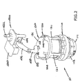
Figure 2 is a perspective view of the flush valve assembly ofFigure 1 ; -
Figure 3 is a schematic perspective view of parts of the toilet flush system ofFigure 1 ; -
Figure 4 is a cross-sectional side view of the flush valve assembly ofFigure 2 ; -
Figure 4A is a cross-sectional side view, on an enlarged scale, of a central part of the flush valve assembly ofFigure 4 ; -
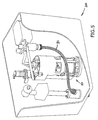
Figures 5 to 7 are perspective views of the toilet flush system ofFigure 1 , showing it in sequential operating conditions; and -
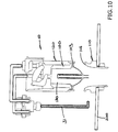
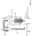
Figures 8 to 14 are cross-sectional side views of the flush valve assembly ofFigure 1 , showing it in sequential operating conditions. - Referring to
Figures 1 to 14 of the drawings, there are shown aflush valve assembly 10 and atoilet flush system 20 incorporating theflush valve assembly 10, both employing the invention. Thetoilet flush system 20 includes atoilet tank 200 which has at its bottom a drain opening 201. Theflush valve assembly 10 is formed by avalve seat 110 provided at (or by) thedrain opening 201, and avalve member 100 which is movable relative to thevalve seat 110, together acting as a flush valve. Theflush valve assembly 10 includes a generally cylindricalhollow structure 120 within which thevalve member 100 is held captive, acting as a guide in sliding engagement with thevalve member 100 for guiding it to move vertically upward and downward. - The
valve seat 110 is a generally cylindrical member which has a lower end 111 inserted through thedrain opening 201 and then secured by an external screw-threadedcollar 112, and anupper end 113 having a annularly ribbeduppermost surface 114 for valve closing engagement with thevalve member 100 above it. - The
valve member 100 has a generally cylindrical hollow body that points downwards and within which aninternal chamber 130 is defined for filling with water for operation. Thevalve member 100 has a pointed (or flat) lower end 101 and a flatupper end 102, and is fitted 360° around its periphery i.e. cylindrical peripheral wall with aflat rubber ring 103 that acts a valve member for cooperation with theuppermost surface 114 of thevalve seat 110 to perform valve closing and opening actions. - In this particular embodiment, the
guide structure 120 sits co-axially on and is integrally connected to thevalve seat 110 by means of several, for example four,integral legs 121, such that theguide structure 120 is fixed to thedrain opening 201. Thevalve member 100, which fits inside theguide structure 120, has fourvertical channels 104 on and around its peripheral wall within which respective protrusions on the inner surface of theguide structure 120 slidably engage such that thevalve member 100 is guided to slide vertically upwards and downwards relative to theguide structure 120. - While being slidable upwards and downwards relative to the
guide structure 120, thevalve member 100 has itsrubber ring 103 arranged for, in a lower position (see e.g.Figure 8 ), sealing engagement with theuppermost surface 114 of thevalve seat 110 to hold water in thetoilet tank 200 and, in an upper position (see e.g.Figure 10 ), dis-engagement from theuppermost surface 114 of thevalve seat 110 to drain water from thetoilet tank 200. - The
valve member 100 is designed to operate with itsinternal chamber 130 arranged to contain water for reducing the buoyancy of thevalve member 100 in water, so that thevalve member 100 may descend through water, before thetoilet tank 200 is completely drained, to reach thevalve seat 110 for sealing engagement therewith. Thevalve member 100 includes aninlet 131 for admitting water into thechamber 130 and anoutlet 132 for discharging water from thechamber 130. Theinlet 131 andoutlet 132 are provided at upper and lower parts of thechamber 130 respectively and, more specifically, the corresponding upper andlower ends 102 and 101 of thevalve member 100. Thechamber 130 includes avent 133 for pressure balancing, which is also provided at theupper end 102 of thevalve member 100. - The
inlet 131 andvent 133 are connected with respective uprightrigid pipes inlet pipe 131P is connected by means of aflexible tube 33 to a water source (i.e. the flush water supply). Thevent pipe 133P has its upper end left open to the ambient atmosphere, extending to a height beyond the highest level of the water in thetoilet tank 200 can get to. - The
chamber 130 includes an internal passage Q (i.e. Q1+Q2+Q3) for discharging water from within thechamber 130. The passage Q has first end Q1 and second end Q2 and extends upwardly from its first end Q1 and then downwardly to its second end Q2 through, and acting as, theoutlet 132 of thechamber 130. At least the first end Q1 of the first and second ends Q1 and Q2 of the passage Q is located at a lowermost part 101 (i.e. the lower end 101) of thechamber 130. To discharge substantially all water from thechamber 130, the passage Q should have its first end Q1 located practically at the lowest possible position in thechamber 130. In this particular embodiment, both of the first and second ends Q1 and Q2 of the passage Q are located at or near the lowermost part 101 of thechamber 130. - The passage Q acts as a syphon passage which serves to discharge water from within the
chamber 130 by syphon action automatically upon the water in thechamber 130 rising over the passage Q, i.e. above the uppermost end or position (Q3) of the passage Q. The passage Q turns from extending upward to extending downward at a position Q3, which is the passage's uppermost position, near an uppermost part 102 (i.e. the upper end 102) of thechamber 130. Preferably, the passage Q extends upwardly and downwardly, both vertically and in a substantially linear manner. - In practice, the siphon passage Q is formed by a pair of vertical outer and inner tubes T1 and T2, with the outer tube T1 extending co-axially outside and along the inner tube T2. The inner tube T2 is open at both of its opposite upper and lower ends, and extends vertically through the
outlet 132 of thechamber 130. The inner tube T2 is integrally connected with the rim of theoutlet 132 such that it is erected centrally and mainly inside thechamber 130, with a relatively short lowermost section projecting downwardly from the lower end 101 of thevalve member 100. - The outer tube T1 has a closed upper end which encloses the open upper end of the inner tube T2 and is connected thereto by means of spacers (not shown), such that the outer tube T1 is wholly supported by the inner tube T2. The outer tube T1 is of about the same length as the main section of the inner tube T2 inside the
chamber 130. - It can be seen that the siphon passage Q has two, first and second sections which are provided by the outer and inner tubes T1 and T2 respectively, with the first section extending between the outer and inner tubes T1 and T2 and the second section extending within the inner tube T2. The first section extends upwardly, and the second section extends downwardly and within and along the length of the first section. The siphon passage Q has a relatively short transition G between the first and second sections, which is the gap between the upper ends of the outer and inner tubes T1 and T2 measured along their length. This transition G or gap should not be too long to avoid excess air trapped in the siphon passage Q, which otherwise would hinder the establishment of a siphon flow.
- The toilet
flush system 20 further includes atank refill mechanism 300 for refilling thetoilet tank 200 with water, and anoperating unit 400 for operating, or controlling the operation of, theflush valve assembly 10. - The
tank refill mechanism 300 has a generally known construction, including awater inlet tube 310 which extends upright through the bottom at a rear corner of thetoilet tank 200, a normally-open valve 320 located at the uppermost end of theinlet tube 310, and afloat 330 slidably mounted on theinlet tube 310. A tee fitting 312 at the bottom of theinlet tube 310 inside thetoilet tank 200 supplies water to theoperating unit 400 via aflexible tube 31. - Water is fed into the
inlet tube 310 via alowermost end 311 thereof, situated immediately underneath thetoilet tank 200. The water travels up along theinlet tube 310 and is then discharged via thevalve 320 into thetoilet tank 200. Thevalve 320 will automatically be closed by, for example, a linkage which is operated by thefloat 330, upon thefloat 330 rising with the water to a predetermined level. - Under the control of the
operating unit 400, the operation of theflush valve assembly 10 involves, at least, valve opening to trigger a flushing action, valve closing to terminate the flushing action, and flush duration control to determine the flush volume. - The
operating unit 400 includes a pair of valves (or referred to as valve devices) 410 and 420, each of which is operated by an electrical solenoid and is generally known as a solenoid valve. Eachsolenoid valve 410/420 includes a normally-closed valve (seee.g. valve member 421 inFigure 3 ) and a solenoid (e.g. designated as 422 inFigure 3 ) for opening the valve for as long as it is being energized by an electrical current. Thesolenoid valves tube 31 for supply of water via theinlet tube 310 and their outlets connected to the liquid-operatesactuator 430 and thevalve member 100 respectively by means of thetubes first solenoid valve 410 controls the supply of water to and hence operates theactuator 430. Thesecond solenoid valve 420 controls the supply of water to and hence operates, or reconditions, thevalve member 100. - Specifically, the
operating unit 400 includes thevalve 420 in a water circuit, which includes thetubes inlet 131 of thevalve member 100 of theflush valve assembly 10 for controlling supply of water into thechamber 130. - As to valve opening, the
operating unit 400 includes anactuator 430 for lifting thevalve member 100 from thevalve seat 110 in order to trigger a flushing action. Theactuator 430 is a liquid-operated actuator which has an internal piston-in-cylinder mechanism, aninlet 432 connected to thetube 32 for supply of water into the cylinder (of the piston-in-cylinder mechanism) of thefirst solenoid valve 410, and anoutput shaft 434 coupled with the piston (of the piston-in-cylinder mechanism) for rotation thereby upon the supply of water into the cylinder. - In operation, the
actuator 430 converts the pressure of the mains flush water into a mechanical force which then rotates theshaft 434 and hence afirst link 436, which is secured at one end to theshaft 434, and in turn pulls up, by means of asecond link 438, thevalve member 100 from thevalve seat 110 to let the water in thetoilet tank 200 flush down into the toilet. - The
operating unit 400 has a number of operating modes, e.g. normal, economic (ECO) and extended modes. Theoperating unit 400 commences a flushing action upon receipt of a control signal which is provided directly or indirectly from a user via a trigger 408 (Figure 3 ) as part of theoperating unit 400. Thetrigger 408 may be a pressure, photoelectric or infrared sensor or any other suitable passive sensors, or a contact (e.g. capacitive) sensor or simply a mechanical switch or any other suitable active sensors. - In the normal mode of operation, upon receipt of a control signal, the
operating unit 400 momentarily (e.g. 100ms as a ballpark figure) opens the first solenoid valve 410 (Figure 9 ) to let the flush water pressure operate theactuator 430 to lift thevalve member 100 from the valve seat 110 (fromFigures 8 to 10 ). During flushing, thevalve member 100 floats on the water in thetoilet tank 200 while the water is being discharged. When the water lowers to a sufficiently low level, it will allow thevalve member 100 to re-engage with thevalve seat 110, whereupon theflush valve assembly 10 closes to terminate the flushing action. In this operation mode, nearly the full tank of water will be discharged. - In the ECO mode of operation, only a portion, e.g. one-third or half, of the water in the toilet tank 200 (i.e. a smaller flush volume than normal) will be discharged by way of early closing of the
flush valve assembly 10 i.e. before the full tank of water is discharged. - For early valve closing, at the end of a predetermined time delay (e.g. 0.5 to 1 second), after the operation of the
first solenoid valve 410, theoperating unit 400 opens thesecond solenoid valve 420 to fill thechamber 130 in thevalve member 100 with water that is supplied via the tube 33 (Figure 11 ). Thevalve member 100 will be filled up with water (i.e. in its valve chamber 130) very quickly and then descend through the water left in thetank 200, as it has already lost its buoyance due to the presence of water in it. Thevalve member 100 will swiftly re-engage with the valve seat 110 (Figure 12 ), whereupon theflush valve assembly 10 closes to terminate the flushing action. - Prior to, during and until completion of the descending of the
valve member 100, thesolenoid valve 420 will be kept open to continue filling thevalve chamber 130 with water. When the water in thevalve chamber 130 rises above the uppermost end of the siphon passage Q, excessive water will overflow and be discharged via the siphon passage Q and then the chamber'soutlet 132, and also thevalve seat 110 and thedrain opening 201, into the toilet below. In practice, as water is being refilled at a higher rate than it overflows, thechamber 130 will be kept fully filled with water (Figures 11 and12 ). - The
operating unit 400 will keep thesolenoid valve 420 open until thevalve member 100 re-engages with the valve seat 110 (Figure 12 ), to ensure that thevalve member 100 will remain fully filled with water, despite losing water by overflowing, such that it will descend (i.e. not buoyant) and close upon thevalve seat 110 to terminate the flushing action. - When the
operating unit 400 finally de-energizes thesolenoid valve 420 to cut off the supply of water, the water in thevalve chamber 130 will start to lower. Upon the water dropping to the uppermost end of the siphon passage Q, a syphon action will be automatically or self-triggered, whereupon the water in thevalve chamber 130 will be discharged (Figure 13 ) via the chamber'soutlet 132, and also thevalve seat 110 and hence thedrain opening 201, into the toilet below. The syphon action will take place until thevalve chamber 130 is completely drained and becomes empty again (Figure 14 ), whereupon the flush system returns to the original condition (Figure 8 ) pending the next flushing action. - In the extended mode of operation, the
operating unit 400 enables a larger flush volume than normal, in that more than the full tank of water in thetoilet tank 200 can be discharged by way of delayed closing of theflush valve assembly 10. This is achieved by way of continuous energization of thefirst solenoid valve 410, which then lifts and maintains thevalve member 100 in a raised position for an extended time period, e.g. up to say 4 to 6 seconds. For as long as thevalve member 100 is being hung, the water pre-stored intoilet tank 200 and then subsequently water replenishing from theinlet tube 310 via thevalve 320 will be let down into the toilet. - The
operating unit 400 further includes anelectronic control circuit 401 which is housed in acase 402 hung internally on the rim of thetoilet tank 200 and is powered by a set ofbattery cells 403. Thecontrol circuit 401 is provided by an MCU 404 for implementing control over the operation of the other functional modules which are atimer circuit 405, a driver circuit 406, atrigger circuit 407 and any other appropriate modules. - The
timer circuit 405 is controllable and/or user-programmable to set the aforesaid predetermined time delay and extended time period for the corresponding modes of operation as described above, and any or all other time periods as are necessary for the operation. In the extended mode of operation, thetimer 405 determines the duration of operation of theactuator 430 lifting thevalve member 100 off thevalve seat 110, thereby determining the flush volume in one or more quantities. - The driver circuit 406 is operable to operate, i.e. energize (open) and de-energize (close), the
solenoid valves - As to the
trigger circuit 407, it is designed to trigger a flushing action as described above upon receipt of a control signal from an aforesaidpassive sensor 408 detecting a certain user condition such as, in particular, when a user leaves the toilet seat. In response, the sensor generates and provides a control signal to thetrigger circuit 407, either directly or via the MCU 404, to operate theactuator 430. Thesensor 408 may alternatively be, or additionally incorporate, a mechanical or touch-sensitive switch that provides a control signal upon active operation by a user. - To enable full manual operation as desired (or as necessary in case of failure of the electrical operation, a manual operator as part of the
operating unit 400 in the form of a pushbutton 440 (Figure 2 ) is provided on thetoilet tank 200, for use as an alternative to theautomatic actuator 430. Thepushbutton 440 is linked to theshaft 434 for depression to rotate theshaft 434 and hence thelinks valve member 100 off thevalve seat 110, thereby triggering a flushing action. Such an operation is very similar to the conventional manual flush operation. - The flush valve assembly of the present invention and a toilet flush system incorporating the same are convenient to use and versatile in terms of functions. They offer automatic operations in a number of modes and yet keep the conventional manual operation as an option or override. In particular, the flush volume may be chosen or programmed by manufacturers/technicians or users, to meet the needs of environmental protection. Battery operation is made possible by the use of the solenoid valves, which only require electrical energization momentarily or for brief periods, as the mechanical actions are driven by the pressure of the mains flush water supply.
- The invention has been given by way of example only, and various other modifications of and/or alterations to the described embodiment may be made by persons skilled in the art without departing from the scope of the invention as specified in the appended claims.
Claims (15)
- A flush valve assembly for use in a toilet tank having at its bottom a drain opening, comprising:a valve seat provided at or by said drain opening; anda valve member movable relative to the valve seat and having a valve part for, in a lower position, sealing engagement with the valve seat to hold water in said toilet tank and, in an upper position, disengagement from the valve seat to drain water from said toilet tank;wherein the valve member includes:an internal chamber for containing water to reduce buoyancy of the valve member in water, so that the valve member may descend through water to reach the valve seat for sealing engagement therewith;an inlet for admitting water into the chamber; andan outlet for discharging water from the chamber.
- The flush valve assembly as claimed in claim 1, wherein the inlet and outlet are provided at upper and lower parts of the chamber respectively;
or alternatively the valve member has a periphery 360° around which the valve part is provided. - The flush valve assembly as claimed in claim 1, wherein the chamber includes an internal passage for discharging water from the chamber, which passage has first and second ends and extends upwardly from its first end and then downwardly to its second end through, and acting as, the outlet of the chamber.
- The flush valve assembly as claimed in claim 3, wherein at least the first end of the first and second ends of the passage is located at a lowermost part of the chamber;
or alternatively the passage turns from extending upward to extending downward at a position near an uppermost part of the chamber;
or alternatively the passage extends upwardly and downwardly both in a substantially linear manner. - The flush valve assembly as claimed in claim 3, wherein the passage has a first section extending upwardly and a second section which extends downwardly and within and along the length of the first section.
- The flush valve assembly as claimed in claim 5, wherein the passage includes a relatively short transition between the first and second sections;
or alternatively the first and second sections of the passage are provided by respective outer and inner tubes, the outer tube having a closed upper end enclosing an open upper end of the inner tube. - The flush valve assembly as claimed in any one of claims 3 to 6, wherein the passage comprises an auto-syphon passage for discharging water from the chamber by syphon action automatically upon water in the chamber rising above the passage.
- The flush valve assembly as claimed in any one of claims 1 to 6, wherein the chamber includes a vent in communication with the ambient atmosphere.
- The flush valve assembly as claimed in claim 8, wherein the vent and the inlet are provided at an upper end of the valve member.
- The flush valve assembly as claimed in any one of claims 1 to 6, including a guide in engagement with the valve member for guiding the valve member to move upwardly and downwardly.
- The flush valve assembly as claimed in claim 10, wherein the guide is in sliding engagement with the valve member;
or alternatively the guide comprises a hollow structure within which the valve member is held captive;
or alternatively the guide is fixed to the drain opening of said toilet tank. - A toilet flush system comprising a toilet tank, a tank refill mechanism for refilling the toilet tank with water, the flush valve assembly as claimed in any one of claims 1 to 6 used in the toilet tank, and an operating unit for operating the flush valve assembly.
- The toilet flush system as claimed in claim 12, wherein the operating unit includes a valve in a water circuit from a water source to the inlet of the valve member of the flush valve assembly for controlling supply of water into the chamber;
- The toilet flush system as claimed in claim 12, wherein the operating unit includes an actuator for lifting the valve member from the valve seat.
- The toilet flush system as claimed in claim 14, wherein the actuator comprises a liquid-operated actuator, and the operating unit includes a valve device for controlling supply of water to operate the actuator;
or alternatively the operating unit includes a manual operator for manually lifting the valve member off the valve seat, as an alternative to the actuator;
or alternatively the operating unit includes a timer for determining the duration of operation of the actuator lifting the valve member off the valve seat, thereby determining the flush volume;
or alternatively the operating unit includes a sensor for sensing a certain condition and in response operating the actuator.
Applications Claiming Priority (1)
| Application Number | Priority Date | Filing Date | Title |
|---|---|---|---|
| US14/600,455 US9932728B2 (en) | 2015-01-20 | 2015-01-20 | Flush valve assembly and toilet flush system incorporating the same |
Publications (1)
| Publication Number | Publication Date |
|---|---|
| EP3048207A1 true EP3048207A1 (en) | 2016-07-27 |
Family
ID=55077445
Family Applications (1)
| Application Number | Title | Priority Date | Filing Date |
|---|---|---|---|
| EP16150690.2A Withdrawn EP3048207A1 (en) | 2015-01-20 | 2016-01-08 | Flush valve assembly and toilet flush system incorporating the same |
Country Status (6)
| Country | Link |
|---|---|
| US (1) | US9932728B2 (en) |
| EP (1) | EP3048207A1 (en) |
| JP (1) | JP2016132985A (en) |
| KR (1) | KR20160089879A (en) |
| CN (1) | CN105804185B (en) |
| TW (1) | TWI683946B (en) |
Cited By (2)
| Publication number | Priority date | Publication date | Assignee | Title |
|---|---|---|---|---|
| DE102017131400A1 (en) | 2017-12-28 | 2019-07-04 | Lixil International Pte. Ltd. | CYLINDER-PISTON UNIT |
| US11193262B2 (en) | 2017-12-28 | 2021-12-07 | As America, Inc. | Combined flushing and filling unit and method for the operation thereof |
Families Citing this family (7)
| Publication number | Priority date | Publication date | Assignee | Title |
|---|---|---|---|---|
| CN104863225A (en) * | 2015-04-27 | 2015-08-26 | 彭东 | Drain valve device controlled based on capacitance variation induction signal |
| JP6578626B2 (en) * | 2017-06-30 | 2019-09-25 | Toto株式会社 | Washing water tank device |
| JP7100290B2 (en) * | 2018-08-29 | 2022-07-13 | Toto株式会社 | Drain valve device |
| US11427995B2 (en) * | 2018-10-10 | 2022-08-30 | Kohler Co. | Quiet flush actuator for pressure-assist toilets |
| CN114382142B (en) * | 2021-08-27 | 2024-06-18 | 厦门齐义成卫浴科技有限公司 | Drain valve with simple flushing device |
| EP4198215B1 (en) | 2021-12-20 | 2026-02-25 | B/E Aerospace, Inc. | Automatic drain valve |
| CN218713648U (en) * | 2022-08-19 | 2023-03-24 | 中山东菱威力洁净科技有限公司 | Automatic driving unit of toilet drain valve and drain valve assembly |
Citations (3)
| Publication number | Priority date | Publication date | Assignee | Title |
|---|---|---|---|---|
| US1946267A (en) * | 1932-05-26 | 1934-02-06 | Becker Nathan | Float tank bulb |
| US3705428A (en) * | 1971-05-24 | 1972-12-12 | James W Braswell | Flushing apparatus |
| US5392470A (en) * | 1994-04-07 | 1995-02-28 | Johnson; Dwight N. | Toilet flush control assembly and methods |
Family Cites Families (11)
| Publication number | Priority date | Publication date | Assignee | Title |
|---|---|---|---|---|
| US2867820A (en) * | 1957-07-08 | 1959-01-13 | Alessandra Gray | Submerged flushing device |
| US2879520A (en) * | 1957-10-14 | 1959-03-31 | Richard L Hollingsworth | Flush valve assembly |
| US3029444A (en) * | 1958-06-26 | 1962-04-17 | Zorzi Carlo | Water supply device for washing w. c. bowls |
| US3816856A (en) * | 1973-05-02 | 1974-06-18 | J Braswell | Flushing apparatus |
| IT1047032B (en) * | 1974-04-12 | 1980-09-10 | Amici F | REFINEMENTS FOR SIPHONS WITH PRESSURE PRIMING AND PNEUMATIC SUCKING |
| AUPM643794A0 (en) * | 1994-06-23 | 1994-07-14 | Dfcu Pty Ltd | Syphonic cistern |
| US6263519B1 (en) * | 2000-04-07 | 2001-07-24 | Arichell Technologies, Inc. | Automatic tank-type flusher |
| CN2880941Y (en) * | 2006-03-24 | 2007-03-21 | 李飞宇 | Water drain valve base of water tank of toilet |
| TWM337594U (en) * | 2008-02-27 | 2008-08-01 | zhi-cheng Yan | Hydraulically-actuated valve set and water closet flushing device equipped with such a valve set |
| US9228334B2 (en) * | 2011-12-19 | 2016-01-05 | Defond Components Limited | Liquid-operated actuator assembly, particularly for a flush toilet, and flush toilet incorporating the assembly |
| HK1206406A1 (en) * | 2012-07-25 | 2016-01-08 | 芙洛玛斯特公司 | Toilet discharge valve assembly having moveable buoyant float therein |
-
2015
- 2015-01-20 US US14/600,455 patent/US9932728B2/en not_active Expired - Fee Related
- 2015-12-21 TW TW104142972A patent/TWI683946B/en not_active IP Right Cessation
-
2016
- 2016-01-08 EP EP16150690.2A patent/EP3048207A1/en not_active Withdrawn
- 2016-01-13 CN CN201610020764.6A patent/CN105804185B/en not_active Expired - Fee Related
- 2016-01-15 JP JP2016005711A patent/JP2016132985A/en active Pending
- 2016-01-19 KR KR1020160006637A patent/KR20160089879A/en not_active Withdrawn
Patent Citations (3)
| Publication number | Priority date | Publication date | Assignee | Title |
|---|---|---|---|---|
| US1946267A (en) * | 1932-05-26 | 1934-02-06 | Becker Nathan | Float tank bulb |
| US3705428A (en) * | 1971-05-24 | 1972-12-12 | James W Braswell | Flushing apparatus |
| US5392470A (en) * | 1994-04-07 | 1995-02-28 | Johnson; Dwight N. | Toilet flush control assembly and methods |
Cited By (4)
| Publication number | Priority date | Publication date | Assignee | Title |
|---|---|---|---|---|
| DE102017131400A1 (en) | 2017-12-28 | 2019-07-04 | Lixil International Pte. Ltd. | CYLINDER-PISTON UNIT |
| WO2019130261A1 (en) | 2017-12-28 | 2019-07-04 | Lixil International Pte. Ltd. | Cylinder-piston unit |
| US11193262B2 (en) | 2017-12-28 | 2021-12-07 | As America, Inc. | Combined flushing and filling unit and method for the operation thereof |
| US11208796B2 (en) | 2017-12-28 | 2021-12-28 | Lixil International Pte. Ltd. | Cylinder-piston unit |
Also Published As
| Publication number | Publication date |
|---|---|
| US9932728B2 (en) | 2018-04-03 |
| KR20160089879A (en) | 2016-07-28 |
| TWI683946B (en) | 2020-02-01 |
| US20160208471A1 (en) | 2016-07-21 |
| JP2016132985A (en) | 2016-07-25 |
| TW201636479A (en) | 2016-10-16 |
| CN105804185B (en) | 2019-05-07 |
| CN105804185A (en) | 2016-07-27 |
Similar Documents
| Publication | Publication Date | Title |
|---|---|---|
| US9932728B2 (en) | Flush valve assembly and toilet flush system incorporating the same | |
| US6510866B2 (en) | Ball cock assembly, float assembly for same, and method of controlling liquid level in a tank | |
| US7200877B2 (en) | Dual flush water saving toilet system | |
| US9464420B2 (en) | Leak detection on flush valve | |
| US3955218A (en) | Self-venting tank valve for toilet tanks | |
| EP2772593A1 (en) | Vacuum breaker, automatic flushing system for toilet, and electronic bidet toilet | |
| EP2759643A2 (en) | Safety system for a bath | |
| CN101638908A (en) | Pressurized dual flush system | |
| CN111943345A (en) | Hydrogen water generator | |
| US9359752B2 (en) | Toilet discharge valve assembly having moveable buoyant float therein | |
| KR101205851B1 (en) | Toilet bowl flush device | |
| EP1162320B1 (en) | Apparatus for flushing a toilet bowl or the like | |
| EP4025743B1 (en) | Flush valve for use in a cistern | |
| US3816856A (en) | Flushing apparatus | |
| US10865553B2 (en) | Toilet flushing system installed in a toilet reservoir | |
| JP2582345Y2 (en) | Float valve device | |
| SE504888C2 (en) | Flushing system for WC chairs | |
| KR101071307B1 (en) | Electric powerless automatic cleaning device for urinal with foot valve and urine device with same | |
| US2318978A (en) | Flush tank | |
| WO1999020850A1 (en) | Valve-actuator for use with a lavatory-flush cistern water-inlet valve | |
| US20080109953A1 (en) | Automatic Flush Toilet Tank Assembly | |
| JP3183602U (en) | Bathing care lift device | |
| GB2330398A (en) | Valve-actuator for cistern | |
| GB2605220A (en) | Improvements to valve assembly and a float therefor | |
| WO2002084035A1 (en) | Flushing apparatus for a toilet or urinal |
Legal Events
| Date | Code | Title | Description |
|---|---|---|---|
| PUAI | Public reference made under article 153(3) epc to a published international application that has entered the european phase |
Free format text: ORIGINAL CODE: 0009012 |
|
| AK | Designated contracting states |
Kind code of ref document: A1 Designated state(s): AL AT BE BG CH CY CZ DE DK EE ES FI FR GB GR HR HU IE IS IT LI LT LU LV MC MK MT NL NO PL PT RO RS SE SI SK SM TR |
|
| AX | Request for extension of the european patent |
Extension state: BA ME |
|
| 17P | Request for examination filed |
Effective date: 20170109 |
|
| RBV | Designated contracting states (corrected) |
Designated state(s): AL AT BE BG CH CY CZ DE DK EE ES FI FR GB GR HR HU IE IS IT LI LT LU LV MC MK MT NL NO PL PT RO RS SE SI SK SM TR |
|
| 17Q | First examination report despatched |
Effective date: 20181005 |
|
| STAA | Information on the status of an ep patent application or granted ep patent |
Free format text: STATUS: THE APPLICATION IS DEEMED TO BE WITHDRAWN |
|
| 18D | Application deemed to be withdrawn |
Effective date: 20190216 |