EP3047773B1 - Robot cleaner and controlling method thereof - Google Patents
Robot cleaner and controlling method thereof Download PDFInfo
- Publication number
- EP3047773B1 EP3047773B1 EP16152153.9A EP16152153A EP3047773B1 EP 3047773 B1 EP3047773 B1 EP 3047773B1 EP 16152153 A EP16152153 A EP 16152153A EP 3047773 B1 EP3047773 B1 EP 3047773B1
- Authority
- EP
- European Patent Office
- Prior art keywords
- robot cleaner
- wall
- sensor
- cleaner
- angular velocity
- Prior art date
- Legal status (The legal status is an assumption and is not a legal conclusion. Google has not performed a legal analysis and makes no representation as to the accuracy of the status listed.)
- Active
Links
Images







Classifications
-
- G—PHYSICS
- G05—CONTROLLING; REGULATING
- G05D—SYSTEMS FOR CONTROLLING OR REGULATING NON-ELECTRIC VARIABLES
- G05D1/00—Control of position, course, altitude or attitude of land, water, air or space vehicles, e.g. using automatic pilots
- G05D1/02—Control of position or course in two dimensions
- G05D1/021—Control of position or course in two dimensions specially adapted to land vehicles
- G05D1/0227—Control of position or course in two dimensions specially adapted to land vehicles using mechanical sensing means, e.g. for sensing treated area
-
- B—PERFORMING OPERATIONS; TRANSPORTING
- B25—HAND TOOLS; PORTABLE POWER-DRIVEN TOOLS; MANIPULATORS
- B25J—MANIPULATORS; CHAMBERS PROVIDED WITH MANIPULATION DEVICES
- B25J11/00—Manipulators not otherwise provided for
- B25J11/008—Manipulators for service tasks
- B25J11/0085—Cleaning
-
- A—HUMAN NECESSITIES
- A47—FURNITURE; DOMESTIC ARTICLES OR APPLIANCES; COFFEE MILLS; SPICE MILLS; SUCTION CLEANERS IN GENERAL
- A47L—DOMESTIC WASHING OR CLEANING; SUCTION CLEANERS IN GENERAL
- A47L9/00—Details or accessories of suction cleaners, e.g. mechanical means for controlling the suction or for effecting pulsating action; Storing devices specially adapted to suction cleaners or parts thereof; Carrying-vehicles specially adapted for suction cleaners
- A47L9/28—Installation of the electric equipment, e.g. adaptation or attachment to the suction cleaner; Controlling suction cleaners by electric means
- A47L9/2836—Installation of the electric equipment, e.g. adaptation or attachment to the suction cleaner; Controlling suction cleaners by electric means characterised by the parts which are controlled
- A47L9/2852—Elements for displacement of the vacuum cleaner or the accessories therefor, e.g. wheels, casters or nozzles
-
- B—PERFORMING OPERATIONS; TRANSPORTING
- B25—HAND TOOLS; PORTABLE POWER-DRIVEN TOOLS; MANIPULATORS
- B25J—MANIPULATORS; CHAMBERS PROVIDED WITH MANIPULATION DEVICES
- B25J13/00—Controls for manipulators
- B25J13/08—Controls for manipulators by means of sensing devices, e.g. viewing or touching devices
-
- B—PERFORMING OPERATIONS; TRANSPORTING
- B25—HAND TOOLS; PORTABLE POWER-DRIVEN TOOLS; MANIPULATORS
- B25J—MANIPULATORS; CHAMBERS PROVIDED WITH MANIPULATION DEVICES
- B25J9/00—Program-controlled manipulators
- B25J9/0003—Home robots, i.e. small robots for domestic use
-
- B—PERFORMING OPERATIONS; TRANSPORTING
- B25—HAND TOOLS; PORTABLE POWER-DRIVEN TOOLS; MANIPULATORS
- B25J—MANIPULATORS; CHAMBERS PROVIDED WITH MANIPULATION DEVICES
- B25J9/00—Program-controlled manipulators
- B25J9/16—Program controls
-
- A—HUMAN NECESSITIES
- A47—FURNITURE; DOMESTIC ARTICLES OR APPLIANCES; COFFEE MILLS; SPICE MILLS; SUCTION CLEANERS IN GENERAL
- A47L—DOMESTIC WASHING OR CLEANING; SUCTION CLEANERS IN GENERAL
- A47L2201/00—Robotic cleaning machines, i.e. with automatic control of the travelling movement or the cleaning operation
- A47L2201/04—Automatic control of the travelling movement; Automatic obstacle detection
-
- Y—GENERAL TAGGING OF NEW TECHNOLOGICAL DEVELOPMENTS; GENERAL TAGGING OF CROSS-SECTIONAL TECHNOLOGIES SPANNING OVER SEVERAL SECTIONS OF THE IPC; TECHNICAL SUBJECTS COVERED BY FORMER USPC CROSS-REFERENCE ART COLLECTIONS [XRACs] AND DIGESTS
- Y10—TECHNICAL SUBJECTS COVERED BY FORMER USPC
- Y10S—TECHNICAL SUBJECTS COVERED BY FORMER USPC CROSS-REFERENCE ART COLLECTIONS [XRACs] AND DIGESTS
- Y10S901/00—Robots
- Y10S901/01—Mobile robot
-
- Y—GENERAL TAGGING OF NEW TECHNOLOGICAL DEVELOPMENTS; GENERAL TAGGING OF CROSS-SECTIONAL TECHNOLOGIES SPANNING OVER SEVERAL SECTIONS OF THE IPC; TECHNICAL SUBJECTS COVERED BY FORMER USPC CROSS-REFERENCE ART COLLECTIONS [XRACs] AND DIGESTS
- Y10—TECHNICAL SUBJECTS COVERED BY FORMER USPC
- Y10S—TECHNICAL SUBJECTS COVERED BY FORMER USPC CROSS-REFERENCE ART COLLECTIONS [XRACs] AND DIGESTS
- Y10S901/00—Robots
- Y10S901/46—Sensing device
Definitions
- the first sensor may be a photo sensor.
- the second detector 100 may be elastically hinge-coupled to the cleaner main body 10, and may be disposed to protrude from an outer circumference of the main body 10 of the robot cleaner 1.
- the opening in the bottom of the main body 10 in which the main brush unit 30 is installed may be a dust inlet 33.
- the main brush unit 30 may be configured of a roller 31 and a main brush 32 protruding from an outer surface of the roller 31.
- the caster 43 may be disposed in a front edge or a rear edge of the bottom of the main body 10 based on a driving direction. A rotation angle of the caster 43 may be changed according to a state of the floor on which the robot cleaner 1 is moving in such a manner that the main body 10 may be kept in a stable posture.
- the driving wheels 41 and 42 and the caster 43 may be configured in one assembly, and may be detachably mounted on the main body 10.
- the rotation unit 110 may move or be depressed to a second position B. Accordingly, the second sensor 130 may generate the second contact signal.
- the first sensor 120 may continuously generate the first contact signal in an ON state.
- the controller 300 to be described later may control the driver 40 according to the second contact signal in preferential consideration of the second contact signal.
- the robot cleaner 1 may start the wall following mode and drive straight along a wall in state S1010.
- the robot cleaner 1 While the robot cleaner 1 approaches the wall, in response to the first and second contact signals not being generated, the robot cleaner 1 may continuously maintain the approach operation in state S1020.
- the robot cleaner 1 may rotate to the first direction approaching the wall to be followed with the fixed angular velocity and approach the wall in state S1020.
- the first direction mentioned as above may be a counterclockwise direction
- the second direction mentioned as above may be a clockwise direction
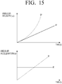
- FIG. 15 illustrates a process that an angular velocity ⁇ and an angular acceleration ⁇ are increased in a process that the angular velocity ⁇ and the angular acceleration ⁇ are changed according to a time t.
- FIG. 16 illustrates a process that an angular velocity ⁇ and an angular acceleration ⁇ are changed from an initial angular velocity ⁇ 1 to a final angular velocity ⁇ 2 to be targeted according to a time t.
Landscapes
- Engineering & Computer Science (AREA)
- Mechanical Engineering (AREA)
- Robotics (AREA)
- Automation & Control Theory (AREA)
- Aviation & Aerospace Engineering (AREA)
- Radar, Positioning & Navigation (AREA)
- Remote Sensing (AREA)
- Physics & Mathematics (AREA)
- General Physics & Mathematics (AREA)
- Human Computer Interaction (AREA)
- Electric Vacuum Cleaner (AREA)
- Control Of Position, Course, Altitude, Or Attitude Of Moving Bodies (AREA)
- Manipulator (AREA)
Description
- Apparatuses and methods consistent with exemplary embodiments relate to a robot cleaner which performs cleaning while driving in a section to be cleaned, and more particularly, to a robot cleaner capable of evenly cleaning the entire cleaning area including an area between a wall and the robot cleaner based on wall following and a controlling method thereof.
- Robot cleaners may automatically clean an area to be cleaned via suctioning foreign materials such as dust from a floor surface while driving the area to be cleaned without user operation.
- The robot cleaners may detect an obstacle (such as a wall) in the area through various sensors and the like and control a driving route and a cleaning operation using the detection result.
- The robot cleaners may repeatedly perform a cleaning task while driving according to a predetermined driving pattern. In response to the obstacle or the wall having a certain length or more being present in the cleaning area, the robot cleaners may perform the cleaning task on an interfacing portion between the obstacle or the wall and a floor through the wall following.
- For the wall following, the robot cleaners may generally employ a bumper sensor operated in response to a bumper being actuated, depressed or squashed due to a collision with the obstacle, the wall, or a distance sensor.
- In response to the bumper signal being detected through the bumper sensor, the robot cleaners using the bumper sensor may drive backward and approach the wall again to perform the wall following. Accordingly, operations of the robot cleaners may be deemed inefficient in terms of time.
- In response to the distance sensor being used in the robot cleaner, the robot cleaners may approach the wall to perform the wall following without collision to the wall or obstacle. However, the robot cleaner may not clean a certain area between the wall and obstacle and the robot cleaner due to limitation and error for effectively sensing area of the sensor.
- A wall-following moving device according to
US 2012/065829 A1 consists of a base, a determining drive unit, multiple collision sensing units, two signal transceiver units arranged at the same lateral side of the base parallel to the moving direction of the base for synchronously transmitting and receiving specific signals, and being electrically connected to the determining drive unit, and a moving element mounted to the base and controlled by the determining drive unit to perform various movements. The determining drive unit compares two reflected signals from a wall received separately by two signal transceiver units, and uses the intensity difference of the signals as a basis to control the moving element to orientate the robot parallel to the wall. By an intricate coordination of the collision sensing units, two signal transceiver units, determining drive unit, and the moving element, the distance between the robot and a wall can be precisely determined and controlled. - According to
US 2014/150820 A1 a cleaning robot and a control method thereof include a main body traveling on a floor, and a first sub-cleaning tool and a second sub-cleaning tool mounted at left and right sides of the main body so as to be protruded from the inside to the outside of the main body and selectively performing cleaning. Insertion of at least one of the first sub-cleaning tool and the second sub-cleaning tool is controlled when the main body is rotated under the condition that an obstacle is detected. Side brushes of the sub-cleaning tools are inserted into the main body according to the rotation direction of the main body when the main body is rotated during traveling, thus preventing collision with the obstacle. - In
EP 2 325 714 A2 a control method of a robot cleaner is disclosed in which a robot cleaner is moved at an arbitrary starting angle along a rotation trajectory having an arbitrary rotational center and rotation radius during obstacle-following traveling, whereby an obstacle-following traveling time is reduced and consequently, a movement time of the robot cleaner is reduced. According to a method disclosed inUS 6,142,252 , when an autonomous vehicle detects an interruption in a wall, a plurality of optical distance measurement sensors provided in a driving unit measures the distance to a plurality of points of an object of interest located ahead. The configuration of the object of interest located ahead is recognized from the obtained distance information and from the attached angle of each optical distance measurement sensor to determine the subsequent operation of the autonomous vehicle. -
US2005/0251292 A1 discloses another wall-following operation of a robot cleaner. - Exemplary embodiments may overcome the above disadvantages and other disadvantages not described above. Also, an exemplary embodiment is not required to overcome the disadvantages described above, and an exemplary embodiment may not overcome any of the problems described above.
- One or more exemplary embodiments relate to a robot cleaner capable of cleaning the whole area between a wall and the robot cleaner by performing wall following using the contact sensor through rotation with an angular velocity corresponding to each step according to a contact signal for the step generated from a contact sensor without driving backward even in response to the contact sensor being in contact with the wall or an obstacle, and a controlling method thereof.
- According to an aspect of an exemplary embodiment, there is provided a robot cleaner according to
claim 1. The first detector may include a plurality of distance sensors disposed in a front of the cleaner main body. - A rotation unit of the plurality of rotation units may be configured to be reciprocally rotated based on a hinge connector from an initial position in which the rotation unit protrudes more from the outer circumference of the cleaner main body to a maximum lead-in position to an interior of the cleaner main body. Outer surfaces of the plurality of rotation units may curvedly protrude.
- The first sensor may be disposed in each of the outer surfaces of the plurality of rotation units. The first sensor may include at least one tactile sensor.
- The first sensor may be disposed in the cleaner main body, and may be established in a position closer to the plurality of rotation units than the second sensor.
- The first sensor may be a photo sensor.
- The second sensor may be a micro switch configured to generate the second contact signal by being pressed by the plurality of rotation units.
- The second sensor may be a photo sensor configured to detect the plurality of rotation units which are led into the inside of the cleaner main body.
- An auxiliary brush unit may be rotatably coupled to a bottom of each of the plurality of rotation units.
- According to an aspect of an exemplary embodiment, there is provided a method of controlling a robot cleaner according to
claim 12. The method may further include allowing the robot cleaner to drive backward in response to an on state of the second sensor being maintained beyond a preset time. - Additional aspects and advantages of the exemplary embodiments are set forth in the detailed description, and will be obvious from the detailed description, or may be learned by practicing the exemplary embodiments.
- The above and/or other aspects of the present disclosure will be more apparent by describing certain exemplary embodiments of the present disclosure with reference to the accompanying drawings, in which:
-
FIG. 1 is a bottom view illustrating a robot cleaner according to an exemplary embodiment; -
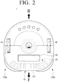
FIG. 2 is a plan view illustrating the robot cleaner illustrated inFIG. 1 ; -
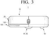
FIG. 3 is a side view illustrating the robot cleaner illustrated inFIG. 1 ; -
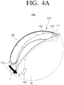
FIGS. 4A and4B are enlarged bottom views illustrating a portion A of the robot cleaner illustrated inFIG. 1 ; -
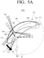
FIGS. 5A and5B are enlarged bottom views illustrating a portion A of the robot cleaner illustrated inFIG. 1 according to another exemplary embodiment; -
FIG. 6 is a plan view illustrating an auxiliary brush unit illustrated inFIG. 1 ; -
FIG. 7 is a side view illustrating an example of a first sensor and a second sensor in the form of a photo sensor according to an exemplary embodiment; -
FIG. 8 is a diagram illustrating a control block of a robot cleaner according to an exemplary embodiment; -
FIGS. 9A and9B are diagrams illustrating generation of first and second contact signals of a robot cleaner according to an exemplary embodiment; -
FIG. 10 is a sequence diagram illustrating a wall following process of a robot cleaner according to an exemplary embodiment; -
FIG. 11 is a diagram illustrating a wall following process of a robot cleaner according to an exemplary embodiment; -
FIG. 12 is a plan view illustrating a trajectory generated in the wall following process ofFIG. 11 ; -
FIG. 13 is a flowchart illustrating a controlling method of a robot cleaner in a left wall following mode according to an exemplary embodiment; -
FIG. 14 is a flowchart illustrating a controlling method of a robot cleaner in a right wall following mode according to an exemplary embodiment; -
FIG. 15 is a diagram illustrating an increasing process of an angular velocity and an angular acceleration according to an exemplary embodiment; and -
FIG. 16 is a diagram illustrating a changing process of an angular velocity and an angular acceleration from an initial angular velocity to a final angular velocity an exemplary embodiment. - Hereinafter, the exemplary embodiments are described in greater detail with reference to the accompanying drawings.
- Specific exemplary embodiments will be described with reference to accompanying drawings and detailed explanation.
- With regard to the descriptions of drawings, similar reference numerals can be used for similar elements. In addition, the terms such as "first" and "second" used in the description can modify various elements regardless of an order and/or a level of importance, and these terms may be used for the purpose of distinguishing one element from another element, not for limiting the elements. For example, "the first sensor," and "the second sensor" can indicate different parts regardless of an order or a level of importance. For example, without departing the scope of the invention, a first element can be termed a second element, and a second element can be termed a first element in a similar manner.
- In the following description, unless otherwise described, the same reference numerals are used for the same elements when they are depicted in different drawings. The matters defined in the description, such as detailed construction and elements, are provided to assist in a comprehensive understanding of the exemplary embodiments. Thus, it is understood that the exemplary embodiments can be carried out without those specifically defined matters. Also, functions or elements known in the related art are not described in detail since they would obscure the exemplary embodiments with unnecessary detail.
-
FIG. 1 is a bottom view illustrating arobot cleaner 1 according to an exemplary embodiment,FIG. 2 is a plan view illustrating therobot cleaner 1 illustrated inFIG. 1 , andFIG. 3 is a side view illustrating therobot cleaner 1 illustrated inFIG. 1 . - Referring to
FIGS. 1 to 3 , therobot cleaner 1 according to an exemplary embodiment may be configured to generate a wall detection signal through afirst detector 20, generate first and second contact signals according to a contact with a wall to be followed through asecond detector 100, and smoothly follow the wall by controlling therobot cleaner 1 to rotate based on different angular velocities corresponding to the first and second contact signals, thereby efficiently cleaning an area between the wall and therobot cleaner 1. - The
robot cleaner 1 according to an exemplary embodiment may include thefirst detector 20 configured to generate the wall detection signal by detecting the wall, thesecond detector 100 configured to generate the first and second contact signals through the contact with the wall, a cleanermain body 10 in which thefirst detector 20 and thesecond detector 100 are disposed and includes a driver 40 (FIG. 8 ) configured to move therobot cleaner 1 about a surface or an area to be cleaned, a main brush unit 30 (including aroller 31 and a main brush 32) configured to introduce and sweep dust on the surface to a suction port, and apower unit 50 configured to supply driving power for driving themain body 10 and thedriver 40. - The
first detector 20 may be disposed in afront 102 of therobot cleaner 1 and include a plurality of distance sensors. Thefirst detector 20 may detect a wall to be followed by therobot cleaner 1 according to a wall following mode. For example, in response to therobot cleaner 1 moving in one direction without a predetermined route, thefirst detector 20 or the plurality of distance sensors may generate a wall detection signal by detecting a neighboring wall. Therobot cleaner 1 may move along the wall according to the wall detection signal generated. Thefirst detector 20 may be implemented with various types including a proximity sensor or a vision sensor other than the distance sensors, but thefirst detector 20 is not limited thereto. - The
second detector 100 may be elastically hinge-coupled to the cleanermain body 10, and may be disposed to protrude from an outer circumference of themain body 10 of therobot cleaner 1. - The
second detector 100 having the configuration may generate the first and second contact signals through the contact with the wall followed by therobot cleaner 1. Thesecond detector 100 may be configured to include one of a tactile sensor, a photo sensor, and a micro switch, but thesecond detector 100 is not limited thereto. - The
second detector 100 may be disposed in such a manner that an auxiliary brush unit 140 (ofFIG. 5A andFIG. 5B ) is rotatable. Thesecond detector 100 will be described later with reference toFIGS. 4A to 5B . - The cleaner
main body 10 may form an outer appearance of therobot cleaner 1 and various parts configured to operate therobot cleaner 1 may be disposed in the cleanermain body 10. - The
main brush unit 30 may be mounted on an opening (not shown) formed in a portion of a bottom of themain body 10 biased to an upper part F from a central region of the bottom. Themain brush unit 30 may clean foreign materials such as dust accumulated on a floor on which themain body 10 is laid. - The opening in the bottom of the
main body 10 in which themain brush unit 30 is installed may be adust inlet 33. Themain brush unit 30 may be configured of aroller 31 and amain brush 32 protruding from an outer surface of theroller 31. - The
main brush 32 may introduce the dust into thedust inlet 33 by whisking the dust accumulated on the floor through rotation of the motor. Theroller 31 may be formed of a rigid material, but the material for theroller 31 is not limited thereto. - The
main brush 32 may be formed of various materials having elasticity. Although not shown in drawings, a blower configured to generate suction force may be provided in thedust inlet 33, and may allow the dust flowing from thedust inlet 33 to a dust collector (not shown). - The
power unit 50 may include a battery electrically coupled to driving devices configured to drive themain body 10 and various parts mounted on themain body 10 and configured to supply the driving power to the driver 40 (ofFIG. 8 ). The battery may include a rechargeable secondary battery, and may be recharged by receiving power from a docking station (not shown) in response to themain body 10 being coupled to the docking station after a cleaning process. - The
driver 40 may include drivingwheels caster 43. - Two driving
wheels main body 10 based on the central region. The drivingwheels - The
caster 43 may be disposed in a front edge or a rear edge of the bottom of themain body 10 based on a driving direction. A rotation angle of thecaster 43 may be changed according to a state of the floor on which therobot cleaner 1 is moving in such a manner that themain body 10 may be kept in a stable posture. The drivingwheels caster 43 may be configured in one assembly, and may be detachably mounted on themain body 10. - A
display 60 may be disposed in a top of therobot cleaner 1, and display various states of therobot cleaner 1. For example, thedisplay 60 may display a battery charge state, a full state of dust in a dust collector (not shown), a cleaning mode, a wall following mode, and a sleep mode of therobot cleaner 1, and the like. - Although not shown in drawings, the
robot cleaner 1 according to an exemplary embodiment may include an input unit, and may receive, for example, a command for the cleaning mode, the wall following mode, the sleep mode, power on/off, and the like from the user through the input unit. -
FIGS. 4A and4B are enlarged views illustrating a portion A of therobot cleaner 1 illustrated inFIG. 1 . - Referring to
FIGS. 4A and4B , thesecond detector 100 according to an exemplary embodiment may include thesecond detector second detector rotation units 110, first sensors, and second sensors. - The
rotation unit 110 may be elastically hinge-coupled to an inner side of themain body 10 of therobot cleaner 1 and at least of which may protrude from the outer circumference of therobot cleaner 1. - For example, the
rotation unit 110 may protrude from thefront 102 of therobot cleaner 1, and may be supported to an outward direction of therobot cleaner 1 by an elastic member (not shown) disposed in the inside of themain body 10. - The
rotation unit 110 may make contact with a wall earlier than themain body 10 at the moment when therobot cleaner 1 makes contact with the wall. Therotation unit 110 may be reciprocally rotated based on ahinge connector 114 from an initial position (A position) in which therotation unit 110 protrudes more from the outer circumference of the cleanermain body 10 to a maximum lead-in position (B position) to an interior of the cleanermain body 10. - The outer surface of the
rotation unit 110 may extend to curvedly protrude, for example, along an outer circumference of a side from the front of therobot cleaner 1. Thehinge connector 114 of therotation unit 110 may be disposed in the front of the robot cleaner, but this is not limited thereto. Thehinge connector 114 may be disposed in the one side of therobot cleaner 1. Even in response to an angle between the wall and the moving direction of therobot cleaner 1 being extremely small, therotation unit 110 may make contact with the wall earlier than the cleanermain body 10. - In response to the
robot cleaner 1 continuously pressing against the wall, therotation unit 110 may be pressed toward the interior of therobot cleaner 1, between atop plate 11 and abottom plate 12 of therobot cleaner 1. In response to therobot cleaner 1 no longer making contact with the wall, therotation unit 110 may spring back from the interior of therobot cleaner 1 to protrude along the outer circumference of therobot cleaner 1 by an elastic member (not shown) again. - For example, the
second detector 100a may be configured to includeatactile sensor 120 disposed in theouter surface 111 of therotation unit 110 among the first sensor. - For example, the first sensor in the form of a
tactile sensor 120 may be disposed to surround theouter surface 111 of therotation unit 110. In this way, the first sensor (the tactile sensor 120) may generate the first contact signal through making contact with the wall in response to therobot cleaner 1 moving to the wall. As the tactile sensor is disposed to surround theouter surface 111 of therotation unit 110, the tactile sensor may generate the first contact signal in response to any point along therotation unit 110 making contact with the wall. - In another example, the
second detector 101a may be configured to include the first sensor in the form of aphoto sensor 150a. In this example, thephoto sensor 150a may further include a light emitter (e.g.,light emitter 151 ofFIG. 7 ) and a light receiver (e.g.,light receiver 152 ofFIG. 7 ). Thephoto sensor 150a may be operated by detecting a variation of light emitted from thelight emitter 151, irradiated to and reflected from an object, and then reached to thelight receiver 152 or position change in light-receiving positions (see P1 and P2 ofFIG. 7 ). For example, thephoto sensor 150a may be disposed in the cleanermain body 10. In another example, thephoto sensor 150a may be disposed in a surface of therotation unit 110. The detailed configuration and operation of thephoto sensor FIG. 7 . - The exemplary embodiment has described that the first sensor may include the
tactile sensor 120 and thephoto sensor 150a, but the first sensor are not limited thereto. - For example, the
second detector 100a may be configured to include a second sensor in the form of amicro switch 130 disposed in the interior of therobot cleaner 1. - In this example, the
micro switch 130 constituting the second sensor may generate the second contact signal by being pressed by aninner surface 112 of therotation unit 110 led into the inside of therobot cleaner 1. - In another example, the
second detectors 101a may be configured to include aphoto sensor 150b disposed in the interior of therobot cleaner 1 among the second sensor. The configuration and operation of thephoto sensor 150b are similar to those of the photo sensor 150aconstituting the first sensors, and thus detailed description thereof will be omitted. - The exemplary embodiment has described that the second sensor may include the
micro switch 130 and thephoto sensor 150b, respectively, but the second sensors are not limited thereto. - In the meantime, with respect to a pair of the second detector as illustrated in
FIG.1 , the first and second sensors may be selectively applied. In other words, the selectively applying means that, as for the second detector (100a) of the part A, the first sensor may be applied as atactile sensor 120 as illustrated inFIG.4A , the second sensor may be applied as amicro switch 130, and as for the second detector (100b) in an opposite side of the part A, both the first and second sensors may be applied as anoptical sensor FIG.4B . -
FIGS. 5A and5B are enlarged views illustrating a portion A of therobot cleaner 1 illustrated inFIG. 1 according to another exemplary embodiment. - Referring to
FIGS. 5A and5B , thesecond detector 100 according to another exemplary embodiment may includesecond detectors second detector rotation units 110, the first sensor, the second sensor, andauxiliary brush units 140. Thesecond detector second detector second detector auxiliary brush units 140. - Hereinafter, description for the configuration of the
second detector second detector - The
second detector rotation units 110 of which theauxiliary brush units 140 are installed in abottom 113 thereof. The exemplary embodiment has described that theauxiliary brush unit 140 is installed in thebottom 113 of therotation unit 110, but this is not limited thereto. - In the
second detector robot cleaner 1 follows the wall, theauxiliary brush unit 140 installed in thebottom 113 of therotation unit 110 may introduce dust into thedust inlet 33 by whisking the dust accumulated on the floor. Accordingly, the cleaning efficiency may be improved by introducing the dust accumulated in the area between the wall and therobot cleaner 1 into thedust inlet 33 while therobot cleaner 1 follows the wall. Theauxiliary brush unit 140 installed in therotation unit 110 will be described in detail with reference toFIG. 6 . -
FIG. 6 is a plan view illustrating theauxiliary brush unit 140 illustrated inFIGS. 5A and5B . - Referring to
FIG. 6 , theauxiliary brush unit 140 may be disposed in thebottom 113 of therotation unit 110. Abrush arm 142 may be formed to extend to an outer side of a radius direction of theauxiliary brush unit 140. Thebrush arm 142 may be coupled to arotation shaft 143 and abrush 141 may be coupled to thebrush arm 142. - The
brush 141 may be formed of a soft material so that the first sensor may be in smooth contact with the wall to generate the first contact signal. - The
rotation shaft 143 may be electrically coupled to a motor (not shown) and may receive rotation force. Theauxiliary brush unit 140 which receives the rotation force from the motor (not shown) through therotation shaft 143 may rotate to sweep and collect dust accumulated in an area adjacent to the wall into a pile, or to further scatter the accumulated dust. Accordingly, the cleaning area may increase and thus the area adjacent to the wall or a corner area of the floor may be also cleaned. -
FIG. 7 is a side view illustrating thephoto sensor - Referring to
FIG. 7 , thephoto sensor light emitter 151 and thelight receiver 152. Thephoto sensor light emitter 151, irradiated to and reflected from an object, and then reached to thelight receiver 152 or position change in the light-receiving positions P1 and P2. - For example, the
photo sensor main body 10. In response to the emitted light being irradiated into a floor C to be cleaned, the irradiated emitted light may be reflected from the floor to be cleaned and then incident to thelight receiver 152 along a first trajectory 153-1. The emitted light reflected along the first trajectory 153-1 may form an image in a first light receiving portion P1 in thelight receiver 152. Therotation unit 110 may be deviated from the first position A through the contact made with the wall, compressed into the interior of therobot cleaner 1, and located on the first trajectory 153-1 of the emitted light. Accordingly, the light emitted from thelight emitter 151 of thephoto sensor main body 10 may be reflected from thebottom 113 of therotation unit 110 and incident to thelight receiver 152 along a second trajectory 153-2, and the emitted light may form an image in a second light receiving position P2. - In this example, the
rotation unit 110 may be located closer to thephoto sensor bottom 113 of therotation unit 110 may be greater than the reflected amount of the emitted light reflected from the floor surface C to be cleaned. Thephoto photo sensor - That is, through the operation, the
photo sensor - In response to the first and second sensors being configured of the
photo sensor photo sensor 150a may be established in a position closer to the rotation unit located in the A position than the second sensor. For example, the first sensor disposed in the cleanermain body 10 may be disposed close to therotation unit 110 located in the A position so as to detect therotation unit 110 deviated from the A position. The second sensor may be disposed close to therotation unit 110 located in the B position spaced from the A position so as to detect therotation unit 110 approaching the B position. - Hereinafter, the moving and cleaning operation of the robot cleaner having the above-described configuration according to an exemplary embodiment will be described in detail.
- It may be assumed that the cleaning is typically performed by the main brush unit while driving of the
robot cleaner 1. -
FIG. 8 is a diagram illustrating a control block of therobot cleaner 1 according to an exemplary embodiment. - Referring to
FIG. 8 , therobot cleaner 1 according to an exemplary embodiment may include thefirst detector 20 configured to detect a neighboring wall including a surrounding environment of therobot cleaner 1, thesecond detector 100 configured to generate the first and second contact signals in response to the robot cleaner being in contact with the wall, acontroller 300 configured to control an operation of thedriver 40 according to the first and second contact signals as the detection results of thefirst detector 20 and thesecond detector 100, and thedriver 40 configured to move therobot cleaner 1. - As described above, the
first detector 20 may detect a wall to be followed by therobot cleaner 1 according to the wall following mode. To detect the wall to be followed, thefirst detector 20 which is disposed in the front of therobot cleaner 1 and configured of a plurality of distance sensors may generate a wall detection signal by detecting a neighboring wall. Thefirst detector 20 may be implemented in various types including a proximity sensor or a vision sensor other than the distance sensor, but the first detector is not limited thereto. - As described above, the
second detector 100 may detect the contact of therobot cleaner 1 with the wall. To detect the contact of therobot cleaner 1 with the wall, thesecond detector 100 may be configured of one of a tactile sensor, a photo sensor, and a micro switch, but thesecond detector 100 is not limited thereto. - The
driver 40 may move therobot cleaner 1 as described above. To move therobot cleaner 1, thedriver 40 including the drivingwheels caster 43 may perform a forward driving operation and a backward driving operation of therobot cleaner 1 according to a control signal of the controller as well as a rotation operation according to an angular velocity for a step. - The
controller 300 may control thedriver 40 based on the signals generated from thefirst detector 20 and thesecond detector 100. -
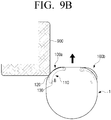
FIGS. 9A and9B are diagrams explaining generation of the first and second contact signals in therobot cleaner 1 according to an exemplary embodiment. - Referring to
FIG. 9A , in response to therobot cleaner 1 according to an exemplary embodiment being in contact with a wall or an obstacle, thefirst sensor 120 of thesecond detector 100a disposed in the left preferentially generate the first contact signal by detecting the contact with anobstacle 900. Therotation unit 110 constituting thesecond detector 100a may be located in the first position A. - Referring to
FIG. 9B , as therobot cleaner 1 further moves to a side of theobstacle 900 in a state that therobot cleaner 1 is making contact with theobstacle 900, therotation unit 110 may move or be depressed to a second position B. Accordingly, thesecond sensor 130 may generate the second contact signal. Thefirst sensor 120 may continuously generate the first contact signal in an ON state. However, in response to the second contact signal being generated from thesecond sensor 130, thecontroller 300 to be described later may control thedriver 40 according to the second contact signal in preferential consideration of the second contact signal. -
FIG. 10 is a sequence diagram illustrating a wall following process of therobot cleaner 1 according to an exemplary embodiment. - Referring to
FIG. 10 , therobot cleaner 1 may start the wall following mode and drive straight along a wall in state S1010. - While the
robot cleaner 1 drives straight, in response to the first and second contact signals not being generated, therobot cleaner 1 may maintain the straight driving in state S1010. - While the
robot cleaner 1 drives straight, in response to the first and second contact signals not being generated within a preset time t_c, therobot cleaner 1 may rotate to a first direction approaching a wall to be followed with a fixed angular velocity and approach the wall in state S1020. - In response to the first contact signal being generated within the preset time while the
robot cleaner 1 drives straight, therobot cleaner 1 may rotate to a second direction spaced from the wall with a first angular velocity, and therobot cleaner 1 may maintain a significant small angular velocity so as to maintain the contact with the wall for a predetermined amount of time or a maximum long time in state S1030. - In response to the first and second contact signals being generated within the preset time while the
robot cleaner 1 drives straight, therobot cleaner 1 may rotate to the second direction spaced from the wall with a second angular velocity, and therobot cleaner 1 may maintain a significant large angular velocity so as to allow therobot cleaner 1 to be spaced from the wall, for example, as soon as possible, in state S1040. - The
robot cleaner 1 may rotate to the first direction approaching the wall to be followed with the fixed angular velocity and approach the wall in state S1020. - While the
robot cleaner 1 approaches the wall, in response to the first and second contact signals not being generated, therobot cleaner 1 may continuously maintain the approach operation in state S1020. - In response to the first contact signal being generated while the robot cleaner approaches the wall, the
robot cleaner 1 may rotate to the second direction spaced from the wall with the first angular velocity, and therobot cleaner 1 may maintain a significant small angular velocity so as to maintain the contact with the wall in state S1030, for example, for a maximum long time. - In response to the first and second contact signals being generated within the preset time while the
robot cleaner 1 approaches the wall, therobot cleaner 1 may rotate to the second direction spaced from the wall with a second angular velocity, and therobot cleaner 1 may maintain a significant large angular velocity so as to allow the robot cleaner to be spaced from the wall as soon as possible in state S1040. - As described above, in response to the first contact signal being generated, the
robot cleaner 1 may rotate to the second direction spaced from the wall with the first angular velocity, and therobot cleaner 1 may maintain a significant small angular velocity so as to maintain the contact with the wall for the maximum long time in state S1030. - In response to the first and second contact signals not being generated, the
robot cleaner 1 may rotate to the first direction approaching the wall to be followed with the fixed angular velocity and approach the wall in state S1020. - As described above, in response to the first contact signal continuously being generated, the
robot cleaner 1 may rotate to the second direction spaced from the wall with the first angular velocity, and therobot cleaner 1 may maintain a significant small angular velocity so as to maintain the contact with the wall, for example, for the maximum long time, in state S1030. - In response to the second contact signal being generated, the
robot cleaner 1 may rotate to the second direction spaced from the wall with the second angular velocity, and therobot cleaner 1 may maintain a significant large angular velocity so as to allow the robot cleaner to be spaced from the wall, for example, as soon as possible, in state S1040. - As described above, in response to the second contact signal being generated, the
robot cleaner 1 may rotate to the second direction spaced from the wall with the second angular velocity, and therobot cleaner 1 may maintain a significant large angular velocity so as to allow the robot cleaner to be spaced from the wall, for example, as soon as possible, in state S1040. - In response to the second contact signal being continuously generated, the
robot cleaner 1 may rotate to the second direction spaced from the wall with the second angular velocity, and therobot cleaner 1 may maintain a significant large angular velocity so as to allow the robot cleaner to be spaced from the wall, for example, as soon as possible, in state S1040. - In response to the first and second contact signals no longer being generated, the
robot cleaner 1 may rotate to the first direction approaching the wall to be followed and approach the wall in state S1020. - In response to the second contact signal being continuously generated beyond a preset time t_tol, the
robot cleaner 1 may perform a backward driving operation in state S1050. -
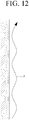
FIG. 11 is a plan view illustrating a wall following process of therobot cleaner 1 according to the exemplary embodiment, andFIG. 12 is a diagram illustrating a trajectory P generated in the wall following process ofFIG. 11 . - Referring to
FIG. 11 , therobot cleaner 1 may start the wall following mode and drive straight along an arrow. While therobot cleaner 1 drives straight, in response to the first and second contact signals not being generated, therobot cleaner 1 may maintain the straight driving, and therotation unit 110 may be located in the first position A in state S1110. - While the
robot cleaner 1 drives straight, in response to the first and second contact signals not being generated within the preset time t_c, therobot cleaner 1 may rotate to the first direction approaching the wall to be followed with a fixed angular velocity and approach the wall, and therotation unit 110 may be located in the first position A in state S1120A. - In response to the first contact signal being generated within the preset time while the
robot cleaner 1 approaches the wall, therobot cleaner 1 may rotate to the second direction spaced from the wall with the first angular velocity, and therobot cleaner 1 may maintain a significantly small angular velocity so as to maintain the contact with the wall for a period of time, for example, a maximum long time. Then, therobot cleaner 1 may be spaced from the wall, and therotation unit 110 may be located in the first position A in state S1130. - However, in response to the
robot cleaner 1 approaching the wall with a large angular velocity and the like, the second contact signal may be generated even in the rotation operation according to the generation of the first contact signal, and therotation unit 110 may be located in the second position in state S1120B. - The
robot cleaner 1 may rotate to the second direction spaced from the wall with the second angular velocity, and therobot cleaner 1 may maintain a significant large angular velocity so as to allow the robot cleaner to be spaced from the wall, for example, as soon as possible. Then, the robot cleaner may be spaced from the wall in state S1130. - Referring to
FIG. 12 , as described above, in response to the first contact signal being generated through the contact made with the wall, therobot cleaner 1 may rotate to the second direction spaced from the wall with the first angular velocity, and therobot cleaner 1 may rotate to the first direction with a significant small angular velocity so as to maintain the contact with the wall, for a period of time, for example, a maximum long time. - In response to the first and second contact signals not being generated within a preset time after the
robot cleaner 1 rotates with the significant small angular velocity and then is spaced from the wall, therobot cleaner 1 may rotate to the first direction with the fixed angular velocity so as to be in contact with the wall again. - Accordingly, the
robot cleaner 1 according to an exemplary embodiment may move while drawing the trajectory P illustrated inFIG. 12 . - Through the movement of the
robot cleaner 1, even in response to therobot cleaner 1 being located between the maximum short distance and the maximum remote distance to the wall, therobot cleaner 1 may clean the area between therobot cleaner 1 and the wall by therotation unit 110 capable of protruding from the outer circumference of therobot cleaner 1 and leading into therobot cleaner 1 and theauxiliary brush unit 140 installed in therotation unit 110. - Accordingly, the
robot cleaner 1 may move via most of the area between the wall and therobot cleaner 1, and thus therobot cleaner 1 may clean most of the area between the wall and therobot cleaner 1. Therobot cleaner 1 may rotate with an angular velocity for a step according to the first and second contact signals without the backward driving in response to therobot cleaner 1 being in contact with the wall and simultaneously may follow the wall, and thus therobot cleaner 1 may efficiently perform the cleaning. -
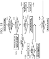
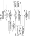
FIG. 13 is a flowchart illustrating a controlling method of therobot cleaner 1 in a left wall following mode, andFIG. 14 is a flowchart illustrating a controlling method of the robot cleaner in a right wall following mode. - The controlling method in the left wall following mode will be described with reference to
FIG. 13 , and the controlling method in the right wall flowing mode is the same as the controlling method in the left wall following method, and thus the controlling method in the right wall following mode will be omitted. - In the controlling method of the
robot cleaner 1 in the left wall following mode, the first direction mentioned as above may be a counterclockwise direction, and the second direction mentioned as above may be a clockwise direction. - First, in response to a wall being detected through the
first detector 20, therobot cleaner 1 may start the wall following mode and start left wall following. - The
robot cleaner 1 may determine whether or not a right first contact signal or a right second contact signal is generated in step S1310. In response to the first and second contact signals being generated through thesecond detector 100 located in the right of therobot cleaner 1 in path S1310-Y during the left wall following of therobot cleaner 1, therobot cleaner 1 may drive backward and rotate to the right with a fixed angular velocity in step S1310A. - The
robot cleaner 1 may drive straight after the rotation, avoid an obstacle expected to be located in the right based on the first and second contact signals generated in the right, and approach the wall again in step S1310B. - In response to the left wall following being satisfied in path S1360-Y, the
robot cleaner 1 may end the left wall following, and in response to the left wall following not being satisfied in path S1360-N, therobot cleaner 1 may start the left wall following again. - In response to the first and second contact signals not being generated through the
second detector 100 located in the right of therobot cleaner 1 in path S1310-N, therobot cleaner 1 may determine whether or not the left second contact signal is generated in step S1320. - In response to the left second contact signal being generated in path S1320-Y, the robot cleaner may increase the angular velocity in the clockwise direction regardless of generation of the left first contact signal, and measure a generation duration time of the second contact signal in step S1320A.
- In response to the left second contact signal being continuously generated in a state that the measured time is beyond a preset time t_tol in path S1340-Y, the
robot cleaner 1 may drive backward and rotate to the right with the fixed angular velocity in step S1310A, and therobot cleaner 1 may drive straight again and approach the wall in step S1310B. Then, in response to the left wall following being satisfied in path S1360-Y, therobot cleaner 1 may end the left wall following, and in response to the left wall following not being satisfied in path S1360-N, therobot cleaner 1 may start the left wall following again. - In response to the measured time not being beyond the preset time t_tol in path S1340-N, the
robot cleaner 1 may proceed to step S1360. In response to the left wall following being satisfied in path S1360-Y, therobot cleaner 1 may end the left wall following, and in response to the left wall following not being satisfied in path S1360-N, therobot cleaner 1 may start the left wall following again. - In response to the left second contact signal not being generated in path S1320-N of the left wall following process, the
robot cleaner 1 may proceed to step S1330. In response to the left first contact signal being generated in path S1330-Y, therobot cleaner 1 may rotate with an angular velocity slightly increased to the clockwise direction in state S1330A. - Then, in response to the left wall following being satisfied in path S1360-Y, the
robot cleaner 1 may end the left wall following, and in response to the left wall following not being satisfied in path S1360-N, therobot cleaner 1 may start the left wall following again. - In response to the left first contact signal not being generated in path S1330-N, the
robot cleaner 1 may measure a duration time in which the left first contact signal is not generated in step S1340A. - Then, in response to the measured duration time being beyond a preset time t_c in path S1350-Y, the robot cleaner may rotate with the angular velocity increased to the counterclockwise direction in step S1350A.
- Then, in response to the left wall following being satisfied in path S1360-Y, the
robot cleaner 1 may end the left wall following, and in response to the left wall following not being satisfied in path S1360-N, therobot cleaner 1 may start the left wall following again. - In response to the measured duration time not being beyond the preset time t_c in path S1350-N, the robot cleaner may proceed to step S1360. In response to the left wall following being satisfied in path S1360-Y, the
robot cleaner 1 may end the left wall following, and in response to the left wall following not being satisfied in path S1360-N, therobot cleaner 1 may start the left wall following again. - Accordingly, the
robot cleaner 1 may move via most of the area between the wall and therobot cleaner 1, and thus therobot cleaner 1 may clean most of the area between the wall and therobot cleaner 1. Therobot cleaner 1 may rotate with an angular velocity for a step according to the first and second contact signals without the backward driving in response to therobot cleaner 1 being in contact with the wall and simultaneously may follow the wall, and thus therobot cleaner 1 may efficiently perform the cleaning. - The exemplary embodiment has described that the
robot cleaner 1 may maintain the fixed angular velocity in response to therobot cleaner 1 approaching the wall or therobot cleaner 1 being spaced from the wall, but this is not limited thereto. For example, the first and second angular velocities may be linearly increased according to preset angular accelerations to reach target angular velocities. In another example, the first and second angular velocities may be increased according to angular accelerations linearly increased to reach target angular velocities. -
FIG. 15 illustrates a process that an angular velocity ω and an angular acceleration α are increased in a process that the angular velocity ω and the angular acceleration α are changed according to a time t. - That is, in response to the angular acceleration being kept to a fixed value along a line A' regardless of the time t, the
robot cleaner 1 may be operated according to the angular velocity linearly increased along a line A". In response to the angular acceleration being linearly increased according to the time t along a line B', therobot cleaner 1 may be operated according to the angular velocity increased in a curve form of a quadratic function along a line B". -
FIG. 16 illustrates a process that an angular velocity ω and an angular acceleration α are changed from an initial angular velocity ω1 to a final angular velocity ω2 to be targeted according to a time t. - That is, in response to being determined that it is necessary to increase the angular velocity to the final angular velocity ω2 in a state that the
robot cleaner 1 rotates with the initial angular velocity ω1, therobot cleaner 1 may be operated according to the angular velocity increased in a curve form of a quadratic function. Therobot cleaner 1 may be gently operated according to the angular velocity increased in a curve form of a quadratic function as compared with the angular velocity linearly increased. - The relationship between the angular velocity ω and the angular acceleration α will be described in detail with reference to
FIG. 16 . - The angular acceleration may be linearly increased in a period from t0 to t1, and the angular velocity corresponding to the angular acceleration may be extremely slowly increased from t0 corresponding to the initial angular velocity ω1. The angular velocity corresponding to the angular acceleration linearly increased may be slowly increased more than the angular velocity corresponding to the fixed angular acceleration. The angular acceleration may be the maximum value at t1 and the angular velocity corresponding to the maximum angular acceleration may be rapidly increased. The angular acceleration may be linearly reduced in a period from t1 to t2. The angular velocity corresponding to the angular acceleration may be still rapidly increased at t1, but the angular velocity may be slowly increased, and may be extremely slowly increased to reach the final angular velocity ω1 at t2.
- The
robot cleaner 1 operated according to the angular velocity as described above may slowly perform the operation for increasing the rotation speed and slowly complete the operation. Accordingly, the load of thedriver 40 in therobot cleaner 1 may be reduced as compared with the operation according to the angular velocity linearly changed.
Claims (13)
- A robot cleaner (1) comprising:a first detector (20) configured to generate a wall detection signal by detecting a wall;a second detector (100) comprising a plurality of rotation units (110), a first sensor configured to generate a first contact signal through contact of the plurality of rotation units (110) with the wall and a second sensor configured to generate a second contact signal;a cleaner main body (10) in which the first and second detectors are disposed and which includes a driver (40) configured to drive on a surface to be cleaned;wherein the plurality of rotation units (110) being elastically hinge-coupled to the cleaner main body and disposed to protrude more than an outer circumference of the cleaner main body, anda controller (300) which is mounted on the cleaner main body and to which the first and second detectors and the driver are electrically coupled, characterized in thatthe controller controls the driver so that the robot cleaner moving to one direction moves along the wall based on the wall detection signal, the robot cleaner rotates to a first rotational direction with a fixed angular velocity, the first rotational direction being a clockwise direction or a counterclockwise direction, to be in contact with the wall in response to the first contact signal not being generated within a preset time,the robot cleaner, while moving, rotates to a second rotational direction opposite to the first rotational direction with a first angular velocity to be spaced from the wall in response to the first contact signal generated by the second detector,wherein the second sensor is configured to generate the second contact signal by detecting the plurality of rotation units rotated toward an inside of the cleaner main body by a preset angle after the first contact signal is generated, andthe robot cleaner, while moving, rotates to the second rotational direction with a second angular velocity greater than the first angular velocity to be spaced from the wall in response to the first contact signal and the second contact signal being generated by the second detector within the preset time, andwherein the first angular velocity is set so as to as to maintain the contact with the wall for a predetermined amount of time or a maximum long time.
- The robot cleaner as claimed in claim 1, wherein the first detector includes a plurality of distance sensors disposed in a front (102) of the cleaner main body.
- The robot cleaner as claimed in claim 1, wherein a rotation unit (110) of the plurality of rotation units (110) is configured to be reciprocally rotated based on a hinge connector (114) from an initial position in which the rotation unit (110) protrudes more from the outer circumference of the cleaner main body (10) to a maximum lead-in position to an interior of the cleaner main body (10).
- The robot cleaner as claimed in claim 1, wherein outer surfaces (111) of the plurality of rotation units curvedly protrude.
- The robot cleaner as claimed in claim 1, wherein the first sensor is disposed in outer surfaces of the plurality of rotation units.
- The robot cleaner as claimed in claim 5, wherein the first sensor includes at least one tactile sensor (120).
- The robot cleaner as claimed in claim 1, wherein the first sensor is disposed in the cleaner main body, and is established in a position closer to the plurality of rotation units than the second sensor.
- The robot cleaner as claimed in claim 7, wherein the first sensor is a photo sensor (150a).
- The robot cleaner as claimed in claim 1, wherein the second sensor is a micro switch (130) configured to generate the second contact signal by being pressed by the plurality of rotation units.
- The robot cleaner as claimed in claim 1, wherein the second sensor is a photo sensor (150b) configured to detect the plurality of rotation units which are led into the inside of the cleaner main body.
- The robot cleaner as claimed in claim 1, wherein an auxiliary brush unit (140) is rotatably coupled to a bottom of each of the plurality of rotation units.
- A method of controlling a robot cleaner (1) for performing wall following, the method comprising:detecting a wall through the robot cleaner (1) moving to one direction;moving the robot cleaner (1) along the wall;the robot cleaner comprising a plurality of rotation units (110) being elastically hinge-coupled to a cleaner main body and disposed to protrude more than an outer circumference of the cleaner main body, a first sensor configured to generate a first contact signal through contact of the plurality of rotation units with the wall, and a second sensor configured to generate a second contact signal,the method being characterized by:turning on the first sensor by rotating the robot cleaner to a first rotational direction with a fixed angular velocity, the first rotational direction being a clockwise direction or a counterclockwise direction, to be in contact with the wall in response to the first sensor not being turned on within a preset time; andturning off the first sensor by rotating the robot cleaner to a second rotational direction opposite to the first rotational direction with a first angular velocity to be spaced from the wall while the robot cleaner moves, andwherein the turning off the first sensor comprises:in response to the first sensor not being turned off and the second sensor being turned on by the plurality of rotation units rotated toward an inside of the cleaner main body by a preset angle within the preset time,sequentially turning off the second sensor and the first sensor by rotating the robot cleaner with a second angular velocity greater than the first angular velocity to the second rotational direction to be spaced from the wall, andwherein the first angular velocity is set so as to as to maintain the contact with the wall for a predetermined amount of time or a maximum long time.
- The method as claimed in claim 12, further comprising allowing the robot cleaner to drive backward in response to an on state of the second sensor being maintained beyond a preset time.
Applications Claiming Priority (1)
| Application Number | Priority Date | Filing Date | Title |
|---|---|---|---|
| KR1020150011305A KR102324204B1 (en) | 2015-01-23 | 2015-01-23 | Robot cleaner and control method thereof |
Publications (2)
| Publication Number | Publication Date |
|---|---|
| EP3047773A1 EP3047773A1 (en) | 2016-07-27 |
| EP3047773B1 true EP3047773B1 (en) | 2021-03-03 |
Family
ID=55221325
Family Applications (1)
| Application Number | Title | Priority Date | Filing Date |
|---|---|---|---|
| EP16152153.9A Active EP3047773B1 (en) | 2015-01-23 | 2016-01-21 | Robot cleaner and controlling method thereof |
Country Status (3)
| Country | Link |
|---|---|
| US (1) | US9914219B2 (en) |
| EP (1) | EP3047773B1 (en) |
| KR (1) | KR102324204B1 (en) |
Families Citing this family (20)
| Publication number | Priority date | Publication date | Assignee | Title |
|---|---|---|---|---|
| CN106081081A (en) * | 2016-06-21 | 2016-11-09 | 深圳市博飞航空科技有限公司 | Can be automatically near unmanned vehicle and the control method of vertical |
| KR102014140B1 (en) | 2017-08-07 | 2019-08-26 | 엘지전자 주식회사 | Robot Cleaner |
| KR102033936B1 (en) | 2017-08-07 | 2019-10-18 | 엘지전자 주식회사 | Robot Cleaner |
| KR102014141B1 (en) * | 2017-08-07 | 2019-10-21 | 엘지전자 주식회사 | Robot Cleaner |
| KR102000068B1 (en) | 2017-08-07 | 2019-07-15 | 엘지전자 주식회사 | Cleaner |
| KR102024089B1 (en) | 2017-08-07 | 2019-09-23 | 엘지전자 주식회사 | Robot Cleaner |
| KR102021828B1 (en) | 2017-08-07 | 2019-09-17 | 엘지전자 주식회사 | Cleaner |
| TWI640750B (en) * | 2017-11-23 | 2018-11-11 | 智棋科技股份有限公司 | Robot system and method for controlling robot |
| KR102045003B1 (en) | 2018-01-25 | 2019-11-14 | 엘지전자 주식회사 | Controlling Method of Robot Cleaner |
| USD855080S1 (en) * | 2018-03-23 | 2019-07-30 | Amazon Technologies, Inc. | Mobile drive unit |
| KR102188797B1 (en) * | 2018-04-02 | 2020-12-08 | 에브리봇 주식회사 | Robot cleaner and method for controling the same |
| KR102122237B1 (en) | 2018-04-30 | 2020-06-15 | 엘지전자 주식회사 | Cleaner and controlling method thereof |
| KR102070282B1 (en) * | 2018-04-30 | 2020-01-28 | 엘지전자 주식회사 | Cleaner and controlling method thereof |
| DE102018117191A1 (en) * | 2018-07-17 | 2020-01-23 | Miele & Cie. Kg | Vacuum robot, charging station for a vacuum robot and method for operating a vacuum robot |
| JP7369592B2 (en) * | 2019-10-30 | 2023-10-26 | 株式会社マキタ | Detection device and robot dust collector |
| CN111374614A (en) * | 2020-03-19 | 2020-07-07 | 北京小米移动软件有限公司 | Control method, device and storage medium for cleaning equipment |
| DE102020208400B4 (en) | 2020-07-03 | 2022-02-24 | BSH Hausgeräte GmbH | PROCEDURE FOR IMPROVED EDGE CLEANING OF A WALL |
| CN116490106B (en) * | 2020-12-04 | 2025-12-19 | 苏州宝时得电动工具有限公司 | Cleaning robot |
| CN116919259A (en) * | 2022-04-08 | 2023-10-24 | 北京石头世纪科技股份有限公司 | Cleaning robot |
| US12619250B2 (en) | 2023-03-03 | 2026-05-05 | Samsung Electronics Co., Ltd. | Ultrasonic piezoelectric transceiver sensor for full surface contact localization |
Citations (1)
| Publication number | Priority date | Publication date | Assignee | Title |
|---|---|---|---|---|
| US20050251292A1 (en) * | 2000-01-24 | 2005-11-10 | Irobot Corporation | Obstacle following sensor scheme for a mobile robot |
Family Cites Families (15)
| Publication number | Priority date | Publication date | Assignee | Title |
|---|---|---|---|---|
| US6142252A (en) * | 1996-07-11 | 2000-11-07 | Minolta Co., Ltd. | Autonomous vehicle that runs while recognizing work area configuration, and method of selecting route |
| US6956348B2 (en) * | 2004-01-28 | 2005-10-18 | Irobot Corporation | Debris sensor for cleaning apparatus |
| US7571511B2 (en) * | 2002-01-03 | 2009-08-11 | Irobot Corporation | Autonomous floor-cleaning robot |
| JP4838978B2 (en) | 2002-12-16 | 2011-12-14 | アイロボット コーポレイション | Autonomous floor cleaning robot |
| JP2006026028A (en) | 2004-07-14 | 2006-02-02 | Sanyo Electric Co Ltd | Cleaner |
| ES2346343T3 (en) * | 2005-02-18 | 2010-10-14 | Irobot Corporation | AUTONOMOUS SURFACE CLEANING ROBOT FOR DRY AND WET CLEANING. |
| US8528157B2 (en) * | 2006-05-19 | 2013-09-10 | Irobot Corporation | Coverage robots and associated cleaning bins |
| KR101281512B1 (en) | 2007-04-06 | 2013-07-03 | 삼성전자주식회사 | Robot cleaner and control method thereof |
| ES2559128T3 (en) * | 2007-05-09 | 2016-02-10 | Irobot Corporation | Autonomous compact covering robot |
| KR100919698B1 (en) | 2007-08-14 | 2009-09-29 | 포항공과대학교 산학협력단 | Cleaning method using cleaning robot |
| KR101406186B1 (en) * | 2009-11-18 | 2014-06-13 | 삼성전자주식회사 | Control method of robot cleaner |
| US20120065829A1 (en) * | 2010-09-15 | 2012-03-15 | Jyh-Cheng Yu | Wall-following Moving Device |
| KR102021894B1 (en) | 2012-10-18 | 2019-11-04 | 엘지전자 주식회사 | Method of controlling an automatic cleaner |
| KR102015311B1 (en) * | 2012-11-30 | 2019-08-28 | 삼성전자주식회사 | Cleaning robot and method for controlling the same |
| US9615712B2 (en) * | 2013-11-12 | 2017-04-11 | Irobot Corporation | Mobile floor cleaning robot |
-
2015
- 2015-01-23 KR KR1020150011305A patent/KR102324204B1/en active Active
-
2016
- 2016-01-21 EP EP16152153.9A patent/EP3047773B1/en active Active
- 2016-01-25 US US15/005,481 patent/US9914219B2/en active Active
Patent Citations (1)
| Publication number | Priority date | Publication date | Assignee | Title |
|---|---|---|---|---|
| US20050251292A1 (en) * | 2000-01-24 | 2005-11-10 | Irobot Corporation | Obstacle following sensor scheme for a mobile robot |
Also Published As
| Publication number | Publication date |
|---|---|
| KR102324204B1 (en) | 2021-11-10 |
| US20160214260A1 (en) | 2016-07-28 |
| EP3047773A1 (en) | 2016-07-27 |
| US9914219B2 (en) | 2018-03-13 |
| KR20160091087A (en) | 2016-08-02 |
Similar Documents
| Publication | Publication Date | Title |
|---|---|---|
| EP3047773A1 (en) | Robot cleaner and controlling method thereof | |
| KR101970541B1 (en) | Robot cleaner and control method for the same | |
| EP3093727B1 (en) | Traveling body device | |
| CN110300537B (en) | Dust collector and control method thereof | |
| EP3328597B1 (en) | Mobile robot and control method thereof | |
| KR102329614B1 (en) | Cleaner and controlling method thereof | |
| EP2457486B1 (en) | Robot cleaner and control method thereof | |
| EP2583609B1 (en) | Robot cleaner and control method for the same | |
| CN104395849B (en) | Systems and methods for guiding a robotic cleaner along a path | |
| EP2583605B1 (en) | Robot cleaner and control method for the same | |
| KR101970582B1 (en) | Robot cleaner and controlling method thereof | |
| KR101938703B1 (en) | Robot cleaner and control method for the same | |
| KR102070066B1 (en) | Robot cleaner and method for controlling the same | |
| CN112055553B (en) | Sweeper and control method thereof | |
| CN106662875A (en) | Autonomous travel body device | |
| KR102122237B1 (en) | Cleaner and controlling method thereof | |
| KR20210015126A (en) | Moving Robot | |
| JP6422703B2 (en) | Autonomous vehicle | |
| KR20150137643A (en) | Robot cleaner and method for controlling the same | |
| JP2016220823A (en) | Self-propelled cleaner | |
| CN114665544A (en) | Self-mobile equipment, charging pile and self-charging system | |
| CN216167276U (en) | Self-moving robot | |
| KR100947364B1 (en) | robotic vacuum | |
| CN113854900A (en) | Self-moving robot | |
| JP2020173621A (en) | Autonomous vacuum cleaner |
Legal Events
| Date | Code | Title | Description |
|---|---|---|---|
| PUAI | Public reference made under article 153(3) epc to a published international application that has entered the european phase |
Free format text: ORIGINAL CODE: 0009012 |
|
| 17P | Request for examination filed |
Effective date: 20160121 |
|
| AK | Designated contracting states |
Kind code of ref document: A1 Designated state(s): AL AT BE BG CH CY CZ DE DK EE ES FI FR GB GR HR HU IE IS IT LI LT LU LV MC MK MT NL NO PL PT RO RS SE SI SK SM TR |
|
| AX | Request for extension of the european patent |
Extension state: BA ME |
|
| STAA | Information on the status of an ep patent application or granted ep patent |
Free format text: STATUS: EXAMINATION IS IN PROGRESS |
|
| 17Q | First examination report despatched |
Effective date: 20170214 |
|
| GRAP | Despatch of communication of intention to grant a patent |
Free format text: ORIGINAL CODE: EPIDOSNIGR1 |
|
| STAA | Information on the status of an ep patent application or granted ep patent |
Free format text: STATUS: GRANT OF PATENT IS INTENDED |
|
| INTG | Intention to grant announced |
Effective date: 20201006 |
|
| GRAS | Grant fee paid |
Free format text: ORIGINAL CODE: EPIDOSNIGR3 |
|
| GRAA | (expected) grant |
Free format text: ORIGINAL CODE: 0009210 |
|
| STAA | Information on the status of an ep patent application or granted ep patent |
Free format text: STATUS: THE PATENT HAS BEEN GRANTED |
|
| AK | Designated contracting states |
Kind code of ref document: B1 Designated state(s): AL AT BE BG CH CY CZ DE DK EE ES FI FR GB GR HR HU IE IS IT LI LT LU LV MC MK MT NL NO PL PT RO RS SE SI SK SM TR |
|
| REG | Reference to a national code |
Ref country code: GB Ref legal event code: FG4D |
|
| REG | Reference to a national code |
Ref country code: AT Ref legal event code: REF Ref document number: 1366282 Country of ref document: AT Kind code of ref document: T Effective date: 20210315 Ref country code: CH Ref legal event code: EP |
|
| REG | Reference to a national code |
Ref country code: DE Ref legal event code: R096 Ref document number: 602016053435 Country of ref document: DE |
|
| REG | Reference to a national code |
Ref country code: IE Ref legal event code: FG4D |
|
| REG | Reference to a national code |
Ref country code: LT Ref legal event code: MG9D |
|
| PG25 | Lapsed in a contracting state [announced via postgrant information from national office to epo] |
Ref country code: NO Free format text: LAPSE BECAUSE OF FAILURE TO SUBMIT A TRANSLATION OF THE DESCRIPTION OR TO PAY THE FEE WITHIN THE PRESCRIBED TIME-LIMIT Effective date: 20210603 Ref country code: BG Free format text: LAPSE BECAUSE OF FAILURE TO SUBMIT A TRANSLATION OF THE DESCRIPTION OR TO PAY THE FEE WITHIN THE PRESCRIBED TIME-LIMIT Effective date: 20210603 Ref country code: GR Free format text: LAPSE BECAUSE OF FAILURE TO SUBMIT A TRANSLATION OF THE DESCRIPTION OR TO PAY THE FEE WITHIN THE PRESCRIBED TIME-LIMIT Effective date: 20210604 Ref country code: HR Free format text: LAPSE BECAUSE OF FAILURE TO SUBMIT A TRANSLATION OF THE DESCRIPTION OR TO PAY THE FEE WITHIN THE PRESCRIBED TIME-LIMIT Effective date: 20210303 Ref country code: FI Free format text: LAPSE BECAUSE OF FAILURE TO SUBMIT A TRANSLATION OF THE DESCRIPTION OR TO PAY THE FEE WITHIN THE PRESCRIBED TIME-LIMIT Effective date: 20210303 Ref country code: LT Free format text: LAPSE BECAUSE OF FAILURE TO SUBMIT A TRANSLATION OF THE DESCRIPTION OR TO PAY THE FEE WITHIN THE PRESCRIBED TIME-LIMIT Effective date: 20210303 |
|
| REG | Reference to a national code |
Ref country code: NL Ref legal event code: MP Effective date: 20210303 |
|
| REG | Reference to a national code |
Ref country code: AT Ref legal event code: MK05 Ref document number: 1366282 Country of ref document: AT Kind code of ref document: T Effective date: 20210303 |
|
| PG25 | Lapsed in a contracting state [announced via postgrant information from national office to epo] |
Ref country code: SE Free format text: LAPSE BECAUSE OF FAILURE TO SUBMIT A TRANSLATION OF THE DESCRIPTION OR TO PAY THE FEE WITHIN THE PRESCRIBED TIME-LIMIT Effective date: 20210303 Ref country code: PL Free format text: LAPSE BECAUSE OF FAILURE TO SUBMIT A TRANSLATION OF THE DESCRIPTION OR TO PAY THE FEE WITHIN THE PRESCRIBED TIME-LIMIT Effective date: 20210303 Ref country code: RS Free format text: LAPSE BECAUSE OF FAILURE TO SUBMIT A TRANSLATION OF THE DESCRIPTION OR TO PAY THE FEE WITHIN THE PRESCRIBED TIME-LIMIT Effective date: 20210303 Ref country code: LV Free format text: LAPSE BECAUSE OF FAILURE TO SUBMIT A TRANSLATION OF THE DESCRIPTION OR TO PAY THE FEE WITHIN THE PRESCRIBED TIME-LIMIT Effective date: 20210303 |
|
| PG25 | Lapsed in a contracting state [announced via postgrant information from national office to epo] |
Ref country code: NL Free format text: LAPSE BECAUSE OF FAILURE TO SUBMIT A TRANSLATION OF THE DESCRIPTION OR TO PAY THE FEE WITHIN THE PRESCRIBED TIME-LIMIT Effective date: 20210303 |
|
| PG25 | Lapsed in a contracting state [announced via postgrant information from national office to epo] |
Ref country code: EE Free format text: LAPSE BECAUSE OF FAILURE TO SUBMIT A TRANSLATION OF THE DESCRIPTION OR TO PAY THE FEE WITHIN THE PRESCRIBED TIME-LIMIT Effective date: 20210303 Ref country code: CZ Free format text: LAPSE BECAUSE OF FAILURE TO SUBMIT A TRANSLATION OF THE DESCRIPTION OR TO PAY THE FEE WITHIN THE PRESCRIBED TIME-LIMIT Effective date: 20210303 Ref country code: SM Free format text: LAPSE BECAUSE OF FAILURE TO SUBMIT A TRANSLATION OF THE DESCRIPTION OR TO PAY THE FEE WITHIN THE PRESCRIBED TIME-LIMIT Effective date: 20210303 Ref country code: AT Free format text: LAPSE BECAUSE OF FAILURE TO SUBMIT A TRANSLATION OF THE DESCRIPTION OR TO PAY THE FEE WITHIN THE PRESCRIBED TIME-LIMIT Effective date: 20210303 |
|
| PG25 | Lapsed in a contracting state [announced via postgrant information from national office to epo] |
Ref country code: IS Free format text: LAPSE BECAUSE OF FAILURE TO SUBMIT A TRANSLATION OF THE DESCRIPTION OR TO PAY THE FEE WITHIN THE PRESCRIBED TIME-LIMIT Effective date: 20210703 Ref country code: SK Free format text: LAPSE BECAUSE OF FAILURE TO SUBMIT A TRANSLATION OF THE DESCRIPTION OR TO PAY THE FEE WITHIN THE PRESCRIBED TIME-LIMIT Effective date: 20210303 Ref country code: RO Free format text: LAPSE BECAUSE OF FAILURE TO SUBMIT A TRANSLATION OF THE DESCRIPTION OR TO PAY THE FEE WITHIN THE PRESCRIBED TIME-LIMIT Effective date: 20210303 Ref country code: PT Free format text: LAPSE BECAUSE OF FAILURE TO SUBMIT A TRANSLATION OF THE DESCRIPTION OR TO PAY THE FEE WITHIN THE PRESCRIBED TIME-LIMIT Effective date: 20210705 Ref country code: ES Free format text: LAPSE BECAUSE OF FAILURE TO SUBMIT A TRANSLATION OF THE DESCRIPTION OR TO PAY THE FEE WITHIN THE PRESCRIBED TIME-LIMIT Effective date: 20210303 |
|
| REG | Reference to a national code |
Ref country code: DE Ref legal event code: R097 Ref document number: 602016053435 Country of ref document: DE |
|
| PLBE | No opposition filed within time limit |
Free format text: ORIGINAL CODE: 0009261 |
|
| STAA | Information on the status of an ep patent application or granted ep patent |
Free format text: STATUS: NO OPPOSITION FILED WITHIN TIME LIMIT |
|
| PG25 | Lapsed in a contracting state [announced via postgrant information from national office to epo] |
Ref country code: AL Free format text: LAPSE BECAUSE OF FAILURE TO SUBMIT A TRANSLATION OF THE DESCRIPTION OR TO PAY THE FEE WITHIN THE PRESCRIBED TIME-LIMIT Effective date: 20210303 Ref country code: DK Free format text: LAPSE BECAUSE OF FAILURE TO SUBMIT A TRANSLATION OF THE DESCRIPTION OR TO PAY THE FEE WITHIN THE PRESCRIBED TIME-LIMIT Effective date: 20210303 |
|
| 26N | No opposition filed |
Effective date: 20211206 |
|
| PG25 | Lapsed in a contracting state [announced via postgrant information from national office to epo] |
Ref country code: SI Free format text: LAPSE BECAUSE OF FAILURE TO SUBMIT A TRANSLATION OF THE DESCRIPTION OR TO PAY THE FEE WITHIN THE PRESCRIBED TIME-LIMIT Effective date: 20210303 |
|
| PG25 | Lapsed in a contracting state [announced via postgrant information from national office to epo] |
Ref country code: IT Free format text: LAPSE BECAUSE OF FAILURE TO SUBMIT A TRANSLATION OF THE DESCRIPTION OR TO PAY THE FEE WITHIN THE PRESCRIBED TIME-LIMIT Effective date: 20210303 |
|
| PG25 | Lapsed in a contracting state [announced via postgrant information from national office to epo] |
Ref country code: IS Free format text: LAPSE BECAUSE OF FAILURE TO SUBMIT A TRANSLATION OF THE DESCRIPTION OR TO PAY THE FEE WITHIN THE PRESCRIBED TIME-LIMIT Effective date: 20210703 |
|
| PG25 | Lapsed in a contracting state [announced via postgrant information from national office to epo] |
Ref country code: MC Free format text: LAPSE BECAUSE OF FAILURE TO SUBMIT A TRANSLATION OF THE DESCRIPTION OR TO PAY THE FEE WITHIN THE PRESCRIBED TIME-LIMIT Effective date: 20210303 |
|
| REG | Reference to a national code |
Ref country code: CH Ref legal event code: PL |
|
| REG | Reference to a national code |
Ref country code: BE Ref legal event code: MM Effective date: 20220131 |
|
| PG25 | Lapsed in a contracting state [announced via postgrant information from national office to epo] |
Ref country code: LU Free format text: LAPSE BECAUSE OF NON-PAYMENT OF DUE FEES Effective date: 20220121 |
|
| PG25 | Lapsed in a contracting state [announced via postgrant information from national office to epo] |
Ref country code: FR Free format text: LAPSE BECAUSE OF NON-PAYMENT OF DUE FEES Effective date: 20220131 Ref country code: BE Free format text: LAPSE BECAUSE OF NON-PAYMENT OF DUE FEES Effective date: 20220131 |
|
| PG25 | Lapsed in a contracting state [announced via postgrant information from national office to epo] |
Ref country code: LI Free format text: LAPSE BECAUSE OF NON-PAYMENT OF DUE FEES Effective date: 20220131 Ref country code: CH Free format text: LAPSE BECAUSE OF NON-PAYMENT OF DUE FEES Effective date: 20220131 |
|
| PG25 | Lapsed in a contracting state [announced via postgrant information from national office to epo] |
Ref country code: IE Free format text: LAPSE BECAUSE OF NON-PAYMENT OF DUE FEES Effective date: 20220121 |
|
| PG25 | Lapsed in a contracting state [announced via postgrant information from national office to epo] |
Ref country code: HU Free format text: LAPSE BECAUSE OF FAILURE TO SUBMIT A TRANSLATION OF THE DESCRIPTION OR TO PAY THE FEE WITHIN THE PRESCRIBED TIME-LIMIT; INVALID AB INITIO Effective date: 20160121 |
|
| PG25 | Lapsed in a contracting state [announced via postgrant information from national office to epo] |
Ref country code: MK Free format text: LAPSE BECAUSE OF FAILURE TO SUBMIT A TRANSLATION OF THE DESCRIPTION OR TO PAY THE FEE WITHIN THE PRESCRIBED TIME-LIMIT Effective date: 20210303 Ref country code: CY Free format text: LAPSE BECAUSE OF FAILURE TO SUBMIT A TRANSLATION OF THE DESCRIPTION OR TO PAY THE FEE WITHIN THE PRESCRIBED TIME-LIMIT Effective date: 20210303 |
|
| PG25 | Lapsed in a contracting state [announced via postgrant information from national office to epo] |
Ref country code: TR Free format text: LAPSE BECAUSE OF FAILURE TO SUBMIT A TRANSLATION OF THE DESCRIPTION OR TO PAY THE FEE WITHIN THE PRESCRIBED TIME-LIMIT Effective date: 20210303 |
|
| PG25 | Lapsed in a contracting state [announced via postgrant information from national office to epo] |
Ref country code: MT Free format text: LAPSE BECAUSE OF FAILURE TO SUBMIT A TRANSLATION OF THE DESCRIPTION OR TO PAY THE FEE WITHIN THE PRESCRIBED TIME-LIMIT Effective date: 20210303 |
|
| PGFP | Annual fee paid to national office [announced via postgrant information from national office to epo] |
Ref country code: GB Payment date: 20251222 Year of fee payment: 11 |
|
| PGFP | Annual fee paid to national office [announced via postgrant information from national office to epo] |
Ref country code: DE Payment date: 20251222 Year of fee payment: 11 |