EP3047758B1 - Mechanism and chair for power combined and independent seat back and leg rest motion - Google Patents
Mechanism and chair for power combined and independent seat back and leg rest motion Download PDFInfo
- Publication number
- EP3047758B1 EP3047758B1 EP16158567.4A EP16158567A EP3047758B1 EP 3047758 B1 EP3047758 B1 EP 3047758B1 EP 16158567 A EP16158567 A EP 16158567A EP 3047758 B1 EP3047758 B1 EP 3047758B1
- Authority
- EP
- European Patent Office
- Prior art keywords
- drive
- leg rest
- swing lever
- seat back
- rod
- Prior art date
- Legal status (The legal status is an assumption and is not a legal conclusion. Google has not performed a legal analysis and makes no representation as to the accuracy of the status listed.)
- Not-in-force
Links
Images


Classifications
-
- A—HUMAN NECESSITIES
- A47—FURNITURE; DOMESTIC ARTICLES OR APPLIANCES; COFFEE MILLS; SPICE MILLS; SUCTION CLEANERS IN GENERAL
- A47C—CHAIRS; SOFAS; BEDS
- A47C1/00—Chairs adapted for special purposes
- A47C1/02—Reclining or easy chairs
- A47C1/022—Reclining or easy chairs having independently-adjustable supporting parts
- A47C1/024—Reclining or easy chairs having independently-adjustable supporting parts the parts, being the back-rest, or the back-rest and seat unit, having adjustable and lockable inclination
- A47C1/0242—Reclining or easy chairs having independently-adjustable supporting parts the parts, being the back-rest, or the back-rest and seat unit, having adjustable and lockable inclination by electric motors
-
- A—HUMAN NECESSITIES
- A47—FURNITURE; DOMESTIC ARTICLES OR APPLIANCES; COFFEE MILLS; SPICE MILLS; SUCTION CLEANERS IN GENERAL
- A47C—CHAIRS; SOFAS; BEDS
- A47C1/00—Chairs adapted for special purposes
- A47C1/02—Reclining or easy chairs
- A47C1/031—Reclining or easy chairs having coupled concurrently adjustable supporting parts
- A47C1/032—Reclining or easy chairs having coupled concurrently adjustable supporting parts the parts being movably-coupled seat and back-rest
- A47C1/03205—Reclining or easy chairs having coupled concurrently adjustable supporting parts the parts being movably-coupled seat and back-rest having adjustable and lockable inclination
- A47C1/03211—Reclining or easy chairs having coupled concurrently adjustable supporting parts the parts being movably-coupled seat and back-rest having adjustable and lockable inclination by electric motors
-
- A—HUMAN NECESSITIES
- A47—FURNITURE; DOMESTIC ARTICLES OR APPLIANCES; COFFEE MILLS; SPICE MILLS; SUCTION CLEANERS IN GENERAL
- A47C—CHAIRS; SOFAS; BEDS
- A47C1/00—Chairs adapted for special purposes
- A47C1/02—Reclining or easy chairs
- A47C1/031—Reclining or easy chairs having coupled concurrently adjustable supporting parts
- A47C1/034—Reclining or easy chairs having coupled concurrently adjustable supporting parts the parts including a leg-rest or foot-rest
- A47C1/0342—Reclining or easy chairs having coupled concurrently adjustable supporting parts the parts including a leg-rest or foot-rest in combination with movable backrest-seat unit or back-rest
-
- A—HUMAN NECESSITIES
- A47—FURNITURE; DOMESTIC ARTICLES OR APPLIANCES; COFFEE MILLS; SPICE MILLS; SUCTION CLEANERS IN GENERAL
- A47C—CHAIRS; SOFAS; BEDS
- A47C17/00—Sofas; Couches; Beds
- A47C17/04—Seating furniture, e.g. sofas, couches, settees, or the like, with movable parts changeable to beds; Chair beds
-
- A—HUMAN NECESSITIES
- A47—FURNITURE; DOMESTIC ARTICLES OR APPLIANCES; COFFEE MILLS; SPICE MILLS; SUCTION CLEANERS IN GENERAL
- A47C—CHAIRS; SOFAS; BEDS
- A47C31/00—Details or accessories for chairs, beds, or the like, not provided for in other groups of this subclass, e.g. upholstery fasteners, mattress protectors, stretching devices for mattress nets
- A47C31/12—Means, e.g. measuring means for adapting chairs, beds or mattresses to the shape or weight of persons
- A47C31/126—Means, e.g. measuring means for adapting chairs, beds or mattresses to the shape or weight of persons for chairs
-
- A—HUMAN NECESSITIES
- A47—FURNITURE; DOMESTIC ARTICLES OR APPLIANCES; COFFEE MILLS; SPICE MILLS; SUCTION CLEANERS IN GENERAL
- A47C—CHAIRS; SOFAS; BEDS
- A47C7/00—Parts, details, or accessories of chairs or stools
- A47C7/36—Support for the head or the back
- A47C7/40—Support for the head or the back for the back
- A47C7/46—Support for the head or the back for the back with special, e.g. adjustable, lumbar region support profile; "Ackerblom" profile chairs
- A47C7/462—Support for the head or the back for the back with special, e.g. adjustable, lumbar region support profile; "Ackerblom" profile chairs adjustable by mechanical means
-
- A—HUMAN NECESSITIES
- A47—FURNITURE; DOMESTIC ARTICLES OR APPLIANCES; COFFEE MILLS; SPICE MILLS; SUCTION CLEANERS IN GENERAL
- A47C—CHAIRS; SOFAS; BEDS
- A47C7/00—Parts, details, or accessories of chairs or stools
- A47C7/50—Supports for the feet or the legs coupled to fixed parts of the chair
- A47C7/506—Supports for the feet or the legs coupled to fixed parts of the chair of adjustable type
- A47C7/5066—Supports for the feet or the legs coupled to fixed parts of the chair of adjustable type by rotation
- A47C7/5068—Supports for the feet or the legs coupled to fixed parts of the chair of adjustable type by rotation actuated by linkages
Definitions
- the present disclosure relates to a furniture member mechanism providing for power combined or independent seat back and leg rest motions.
- Furniture members such as chairs, sofas, loveseats, sectionals, and the like commonly include a mechanism that permits the occupant of the furniture member to manually move a leg rest member from a stowed to an extended position to support the legs of the occupant. Occupant supplied weight/force is commonly required in these furniture members to rotate a seat back member between an upright and a fully reclined position, independent of the mechanism operation moving the leg rest member.
- Power actuators are also known which provide for powered or automatic operation of a leg rest member followed sequentially by powered operation of a seat back member. These designs commonly require the leg rest member to extend first followed by rotation of the seat back member. To reverse the furniture member position, the power actuator is operated to rotate the seat back member forward followed sequentially by retraction of the leg rest member. Independent operation of the leg rest member and seat back member are typically not provided in these designs.
- Each of US-A-2004/256902 , EP-A-619966 , WO-A-96/11607 , US-A-2004/012231 , DE-20108887U and US-A-2002/113477 discloses an actuating mechanism for a reclining seat back and extendible leg rest.
- the present invention provides a furniture member mechanism for power combined and independent seat back and leg rest motion, comprising:
- a furniture member 10 includes a furniture frame assembly 12 which is rotatably supported with respect to a base member 14.
- a seat back member 16 is rotatably connected to furniture frame assembly 12 and can rotate from a fully upright position in a seat back recline direction "A" or return from a fully reclined position in a seat back return direction "B" toward the fully upright position, or be positioned at any position therebetween.
- Seat back member 16 is rotatably connected to furniture frame assembly 12 using oppositely positioned rotational connectors 18 (only one of which is clearly visible in this view).
- Furniture frame assembly 12 includes a first side member 20 positioned with respect to an occupant's right hand side for an occupant seated on furniture member 10, and a second side member 22 positioned on the occupant's left hand side.
- a leg rest member 24 is extensible from a fully stowed position shown in a leg rest extension direction "C” and returnable in a leg rest retraction direction “D” using a mechanism 26 which is connected to each of the furniture frame assembly 12 and base member 14. Movement of the seat back member 16 is also controlled at least in the seat back recline direction "A" by operation of mechanism 26.
- Mechanism 26 includes each of a first actuator device 28 which is used to control rotation of the seat back member 16, and a second actuator device 30 which is used to extend or retract leg rest member 24 as well as to permit a tilting motion of furniture frame assembly 12 with respect to base member 14.
- the tilting motion of furniture frame assembly 12 is with respect to a rear rotation direction "E" and a forward rotation direction “F”.
- Operation of second actuator device 30 simultaneously controls displacement of leg rest member 24 as well as tilt rotation of furniture frame assembly 12. For example, as leg rest member 24 is extended in the leg rest extension direction "C", furniture frame assembly 12 is tilted by rotation in the rear rotation direction "E”. Opposite rotation of leg rest member 24 also causes an opposite rotation of furniture frame assembly 12 in the forward rotation direction "F”.
- First and second actuator devices 28, 30 are identical to each other, and each is rotatably connected to a rigid tube 32.
- Rigid tube 32 is fixedly connected to each of the first and second side members 20, 22 to prevent axial rotation of rigid tube 32. This provides a fixed reference point for operation of either of the first or second actuator devices 28, 30.
- First actuator device 28 is connected to and operates a seat back operating portion 34 of mechanism 26.
- Seat back operating portion 34 includes each of a first seat back actuation link 35 positioned proximate to first side member 20 and a second seat back actuation link 36 positioned proximate to second side member 22.
- a lateral drive member 38 which according to several embodiments is a length of wood material, but can be any suitable material such as metal or plastic, is movably connected with respect to second side member 22 and connected by a seat back linkage set 40 to seat back member 16. Displacement of lateral drive member 38 in a drive member powered motion direction "G" by operation of first actuator device 28 causes a reclining rotation of seat back member 16 in the seat back recline direction "A".
- a rotational fastener 42 is used to rotatably connect seat back linkage set 40 to seat back member 16.
- a forward frame member 44 is oriented substantially perpendicular to and is fixedly connected to each of the first and second side members 20, 22.
- a frame brace 46 which is positioned in an orientation substantially parallel with respect to rigid tube 32 can also be provided, which is also fixedly connected to each of the first and second side members 20, 22.
- each of the first and second actuator devices 28, 30 include an actuator motor 48, 48' which is connected to and provides energy of operation for an actuator drive member 50, 50'.
- actuator motor 48, 48' for each of the first and second actuator devices 28, 30 is operated using a 24-volt DC current.
- a rotary motion of actuator motor 48, 48' is converted to a linear motion by actuator drive member 50, 50', for example using a gear such as a worm gear (not shown).
- An actuator displacement member 52 is connected to and linearly displaced by actuator drive member 50 and provides for opposing linear motions.
- second actuator device 30 has a leg rest and tilt operating portion 54 which converts the fore and aft sliding displacement of the actuator displacement member 52 into an axial rotation of a drive rod 56 which is supported by both first and second side members 20, 22 as well as further components, which will be described in greater detail herein. Included with these further support components are drive rod stiffening braces 58, 58' which are connected to drive rod 56, permitting axial rotation of drive rod 56 while providing lateral support by connection of the drive rod stiffening braces 58, 58' to forward frame member 44. Drive rod stiffening braces 58, 58' therefore permit axial rotation of drive rod 56 while limiting or preventing longitudinal bending of drive rod 56. Axial rotation of drive rod 56 displaces both first and second pantograph linkage sets 60, 62 in the leg rest extension direction "C" which is fixedly connected to leg rest member 24.
- mechanism 26 further includes a support rod 64 which is oriented substantially parallel to drive rod 56 and is positioned forward of drive rod 56 to provide additional support for first and second pantograph linkage sets 60, 62 in their extended positions.
- Support rod 64 does not axially rotate but is supported at opposite ends by first and second side members 20, 22.
- a drive rod free end 66 of drive rod 56 can extend partially outward with respect to first side member 20.
- Drive rod free end 66 can be provided for attachment of a lever (not shown) used for manual rotation of drive rod 56 when electrical power is not available for operation of the second actuator device 30.
- furniture member 10 can be positioned having the seat back member 16 in the fully reclined position simultaneously with the leg rest member 24 being moved to the fully extended position by simultaneous operation of both the first and second actuator devices 28, 30.
- leg rest member 24 extends in the leg rest extension direction "C"
- furniture frame assembly 12 is tilted rearwardly with respect to the rear rotation direction "E”.
- a frame assembly front corner 68 is elevated with respect to a frame assembly rear corner 70 of furniture frame assembly 12 when the leg rest member 24 is in any extended position with respect to forward frame member 44.
- Mechanism 26 of furniture member 10 can also be operated by energizing only one of the first or second actuator devices 28, 30 independently of the other, to either rotate seat back member 16 or extend leg rest member 24.
- Furniture member 10 further provides the option for the operator to return the seat back member 16 to the fully upright position by independent powered operation of first actuator device 28, causing seat back member 16 to rotate in the seat back return direction "B" while the leg rest member 24 is still in any extended position.
- the operator can also return the leg rest member 24 from any extended position to the fully stowed or retracted position by movement in the leg rest retraction direction "D" by independent operation of second actuator device 30, while the seat back member 16 is retained in the upright or any reclined position.
- This optional operation of either the seat back member 16 or the leg rest member 24 is permitted by the independent connection and operation of the first and second actuator devices 28, 30.
- first and second pantograph linkage sets 60, 62 features relating to the drive rod 56, support rod 64, and each of the first and second pantograph linkage sets 60, 62 are shown in greater detail, having the first and second pantograph linkage sets 60, 62 in their fully extended positions.
- drive rod 56 is rotated in a first drive rod rotation direction "H" which is counterclockwise as viewed in Figure 4 .
- This counterclockwise rotation of drive rod 56 is caused by a counterclockwise rotation of first and second leg rest drive links 74, 74'.
- first leg rest drive link 74 is substantially triangular shaped and includes a drive link flange 76 which is fixedly connected to drive rod 56. Axial rotation of drive rod 56 therefore co-rotates the leg rest drive link 74. Rotation of first leg rest drive link 74 in the first drive rod rotation direction "H" also co-rotates a swing link 78 which is rotatably connected to first pantograph linkage set 60. It should be evident that an opposite axial rotation of drive rod 56 in a clockwise rotation direction will cause retraction of the first and second pantograph linkage sets 60, 62.
- a contact flange 80 of leg rest drive link 74 which is oriented substantially perpendicular to a triangular shaped body of first leg rest drive link 74, directly contacts swing link 78 to cause rotation of swing link 78 thereby matching the first drive rod rotation direction "H".
- Swing link 78 is not directly connected to first leg rest drive link 74, but is induced to rotate when pushed by contact flange 80.
- Contact between swing link 78 and first leg rest drive link 74 is normally maintained by a biasing force created by a biasing member 82 which is connected to both first leg rest drive link 74 and swing link 78.
- Swing link 78 is rotatably connected to drive rod 56, and is therefore permitted to freely rotate with respect to drive rod 56.
- a pantograph connecting link 84 is rotatably connected to first pantograph linkage set 60 and rotatably connected to support rod 64.
- the weight of the occupant's legs carried by the leg rest member (not shown in this view) is therefore distributed through both swing link 78 and pantograph connecting link 84. This distributes the occupant's leg weight to each of the drive rod 56 and the support rod 64.
- First pantograph linkage set 60 further includes a leg rest rotational fitting 86 acting as a bearing to permit reduced friction rotation of pantograph connecting link 84 with respect to support rod 64.
- a leg rest connecting flange 88 is provided at a free end of first pantograph linkage set 60 which is used as a mounting surface for leg rest member 24 shown and described in reference to Figure 1 .
- first and second actuator devices 28, 30 are individually rotatably connected to rigid tube 32 using either a first actuator mount bracket 90 or a second actuator mount bracket 92.
- a first actuator mount pin 94 permits first actuator device 28 to rotate with respect to first actuator mount bracket 90.
- a second actuator mount pin 96 permits second actuator device 30 to rotate with respect to second actuator mount bracket 92.
- a drive rod support brace 98 is connected to first actuator mount bracket 90 and also to drive rod 56 to provide additional support for drive rod 56.
- seat back operating portion 34 includes a swing connection tube 100 which is substantially U-shaped and is freely rotatably supported on drive rod 56. Swing connection tube 100 is rotated by extension or retraction of a first actuator extension shaft 102, which is extendable or retractable from actuator displacement member 52' during operation of first actuator device 28. Swing connection tube 100 includes a first tube arm 104 oriented substantially parallel with respect to a second tube arm 106. First tube arm 104 is rotatably connected to drive rod 56 using a first arm bracket 108. Similarly, second tube arm 106 is rotatably connected to drive rod 56 using a second arm bracket 110. First seat back actuation link 35 is rotatably connected to first tube arm 104 using a first spin fitting 112.
- a second spin fitting 114 is used to rotatably connect second seat back actuation link 36 to second tube arm 106.
- Rotation of swing connection tube 100 with respect to drive rod axis of rotation 72 therefore displaces first and second seat back actuation links 35, 36 which are individually connected to and displace each of a first mount plate 116 and a second mount plate 118.
- First mount plate 116 includes an elongated slot 120 which slidably receives support rod 64.
- second mount plate 118 includes an elongated slot 122 to also slidably receive support rod 64.
- Support rod 64 can therefore be substantially fixed in position with respect to drive rod 56 even as the first and second mount plates 116, 118 are displaced in either a forward or a rearward direction by rotation of swing connection tube 100.
- the lateral drive member 38 is fixed to a plate flange 124 extending from first mount plate 116.
- the displacement of second mount plate 118 in a forward or rearward direction by rotation of swing connection tube 100 therefore longitudinally displaces lateral drive member 38, which thereby rotates the seat back member 16 via seat back linkage set 40.
- Support rod 64 which is fixed in position, extends through the individual elongated slots 120, 122. A length of each of the elongated slots 120, 122 is therefore predetermined to accommodate the total forward or rearward displacement of the first or second mount plates 116, 118.
- the second actuator device 30 further includes a second actuator extension shaft 126 which extends in a forward or rearward general direction by operation of second actuator device 30.
- Second actuator extension shaft 126 is connected to a drive toggle connector 128.
- Drive toggle connector 128 is connected to a drive toggle connector extension rod 130 such that drive toggle connector extension rod 130 is co-linearly displaced during displacement of drive toggle connector 128.
- a drive toggle 132 is connected to drive rod 56 and rotatably connected to drive toggle connector 128. Extension of drive toggle connector 128 during extension or retraction of second actuator extension shaft 126 rotates drive toggle 132, thereby axially rotating drive rod 56. Because drive rod 56 is substantially square or rectangular in cross-sectional shape, the geometry of the connectors used between drive toggle 132 and drive rod 56 are also square or rectangular in shape, matching the geometry of drive rod 56.
- a swing lever 134 is rotatably connected to support rod 64 at a swing lever rotation end 136 such that swing lever 134 is freely rotatable with respect to support rod 64.
- drive toggle connector 128 contacts swing lever 134 and thereby rotates swing lever 134 with respect to support rod 64.
- a tilt swing lever 137 is connected to base member 14 using a tilt swing mount bracket 138 and a tilt swing rotation pin 140. Tilt swing lever 137 is rotatably connected to swing lever 134. Rotation of swing lever 134 causes an oppositely directed rotation of tilt swing lever 137.
- a force exerted by drive toggle connector 128 to swing lever 134 and tilt swing lever 137 causes furniture frame assembly 12 to rotate (tilt) during extension of the leg rest assembly (only partially shown with respect to second pantograph linkage set 62). Because support rod 64 is substantially fixed in position with respect to furniture frame assembly 12, as the combination of swing lever 134 and tilt swing lever 137 rotate by displacement of drive toggle connector 128, the tilt swing lever 137 and the swing lever 134 will rotate into a substantially co-linear orientation as will be described in greater detail in reference to Figures 16 and 17 . This linear alignment creates a lifting force pushing upwardly and forwardly on support rod 64, causing rear rotation or tilt of furniture frame assembly 12.
- first actuator device 28 causes rotation of swing connection tube 100 to displace the first and second mount plates 116, 118 but causes no axial rotation of drive rod 56.
- Rotation of drive rod 56 only occurs during operation of second actuator device 30 to both extend the first and second pantograph linkage sets 60, 62 and to produce the rearward tilt of furniture frame assembly 12.
- the support rod 64 is not axially rotatable with respect to a support rod longitudinal axis 142 however support rod 64 is displaceable by the rotation of swing lever 134 and tilt swing lever 137 to produce the rearward tilt of furniture frame assembly 12.
- First actuator device 28 operates to rotate swing connection tube 100 which forwardly displaces each of the first and second seat back actuation links 35, 36. Forward displacement of the first and second seat back actuation links 35, 36, in turn, forwardly and upwardly displace the first and second mount plates 116, 118. Reversing the operation of first actuator device 28 reverses the rotation of swing connection tube 100, thereby retracting the first and second seat back actuation links 35, 36 and second mount plates 116, 118. As previously noted, the forward or rearward displacements of first or second mount plates 116, 118 occur independently of support rod 64 such that support rod 64 remains in position with respect to support rod longitudinal axis 142 during the displacement of first or second mount plates 116, 118.
- independent operation of second actuator device 30 displaces the actuator displacement member 52 thereby rotating drive toggle connector 128 and drive toggle 132.
- Rotation of drive toggle 132 axially rotates drive rod 56, thereby co-rotating both leg rest drive link 74 and swing link 78.
- First pantograph linkage set 60 is not shown for clarity, however it is noted that rotation of both leg rest drive links 74, 74' and swing links 78, 78' act to extend first and second pantograph linkage sets 60, 62 to thereby extend the leg rest member.
- first or second actuator device 28, 30 can be operated at any one time, or because both first and second actuator devices 28, 30 can be simultaneously operated, the occupant can choose either independent operation of the leg rest member or the seat back member, or simultaneous operation of both the leg rest member and seat back member. Any position of either the leg rest member 24 or the seat back member 16 can therefore be selected by the occupant independent of the other.
- the tilt swing lever 137 is rotatably connected to the swing lever 134 using a tilt swing lever pin 144. Tilt swing lever pin 144 therefore displaces both the swing lever 134 and support rod 64 when tilt swing lever 137 is rotated.
- tilt swing lever 137 In the free position shown for tilt swing lever 137, tilt swing lever 137 is freely disposed on drive toggle connector extension rod 130 when the first and second pantograph linkage sets 60, 62 are substantially in their retracted positions. Limited extension of the first and second pantograph linkage sets 60, 62 can occur before drive toggle connector 128 contacts tilt swing lever 137. Continued contact between drive toggle connector 128 and tilt swing lever 137 will thereafter rotate tilt swing lever 137 and swing lever 134, and cause displacement of support rod 64, thereby creating the tilt position of mechanism 26. This will be shown and described in greater detail in reference to Figures 14-17 .
- Rotational bearings 146 are provided for each of the first and second arm brackets 108, 110 (only second arm bracket 110 is clearly visible in this view).
- the rotational bearings 146 permit the axial rotation of drive rod 56 with respect to drive rod axis of rotation 72 independent of the rotation of swing connection tube 100. This allows the rotational axis of swing connection tube 100 to also be maintained coaxial with respect to drive rod axis of rotation 72 without requiring co-rotation of swing connection tube 100 as drive rod 56 rotates.
- mechanism 26 in addition to the capability of mechanism 26 to provide for leg rest extension and retraction and seat back rotation, mechanism 26 further provides for a rocking motion of furniture frame assembly 12 with respect to base member 14 by manual force/weight distribution of the occupant of furniture member 10, as commonly known.
- This rotation or rocking motion of furniture frame assembly 12 can be controlled using an opposed set of rocker spring assemblies 148, 148' (only second rocker spring assembly 148' is clearly visible in this view).
- the rocker spring assemblies 148, 148' are connected to the first and second side members 20, 22 and to the base member 14.
- the axis of rotation for the rocking motion of furniture frame assembly 12 with respect to base member 14 is therefore determined by the position of the rocker spring assemblies 148, 148'.
- rocking motion of furniture frame assembly 12 occurs with respect to a rearward rocking direction "J" and an opposite forward rocking direction "K".
- rocking direction motions are independent of rear and forward rotation directions "E", “F” because the rear and forward rotation directions "E", “F” are oriented with respect to drive rod axis of rotation 72.
- first actuator device 28 is operated to retract first actuator extension shaft 102 with respect to actuator displacement member 52'. Because first actuator extension shaft 102 is rotatably connected to a first actuator connecting bracket 150, which is also connected to swing connection tube 100, this retraction of first actuator extension shaft 102 rotates swing connection tube 100 in a swing rotation direction "L" with respect to drive rod axis of rotation 72. Again and as previously noted, rotation of swing connection tube 100 in the swing rotation direction "L" does not result in an axial rotation of drive rod 56.
- the weight of the occupant seated on furniture frame assembly 12 also assists in retracting lateral drive member 38 in a direction opposite to drive member powered motion direction "G", thereby permitting the rotation of seat back member 16 away from the fully retracted and back to the fully forward position.
- the weight of the occupant of furniture member 10, as well as any force provided by the occupant, therefore assists in the return of seat back member 16 to the upright position instead of this rotation being an entirely powered operation.
- first and second pantograph linkage sets 60, 62 With the first and second pantograph linkage sets 60, 62 positioned in the fully retracted positions (only second pantograph linkage set 62 is clearly visible in this view), the first and second pantograph linkage sets 60, 62 are each received in an individual one of a first pantograph clearance aperture 152 or a second pantograph clearance aperture 154.
- the first and second pantograph clearance apertures 152, 154 are each created in the forward frame member 44.
- leg rest member 24 When leg rest member 24 is positioned in the stowed position, leg rest member 24 contacts forward frame member 44.
- the first and second pantograph clearance apertures 152, 154 permit a continuous connection between first and second pantograph linkage sets 60, 62 and leg rest member 24 through forward frame member 44 in any position of leg rest member 24.
- leg rest drive link 74 is shown in the position corresponding to a fully retracted position of the first and second pantograph linkage sets 60, 62 (only first pantograph linkage set 60 is shown in this view).
- leg rest drive link 74 is also co-rotated in the first drive rod rotation direction "H”.
- the contact flange 80 of leg rest drive link 74 provides direct contact between leg rest drive link 74 and swing link 78 at an edge face 156 of swing link 78. This direct contact causes simultaneous rotation of swing link 78 as leg rest drive link 74 rotates in the first drive rod rotation direction "H".
- swing link 78 is freely rotationally positioned with respect to drive rod 56 and therefore does not directly rotate in response to rotation of drive rod 56.
- a rotational fastener 158 connecting swing link 78 to a link connecting end 160 of first pantograph linkage set 60 transfers the rotational motion of swing link 78 to a forward translation of link connecting end 160 and therefore to first pantograph linkage set 60.
- leg rest drive link 74 is shown following rotation of drive rod 56 in the first drive rod rotation direction "H", causing full extension of both first and second pantograph linkage sets 60, 62. At this time, leg rest drive link 74 is rotated greater than 90 degrees and approximately 110 degrees with respect to its orientation in the leg rest fully retracted position shown and described in Figure 8 .
- pantograph connecting links 84, 84' also distribute a portion of the occupant's leg weight to support rod 64.
- first and second pantograph clearance apertures 152, 154 provided in forward frame member 44, provide clearance for maximum extension of first and second pantograph linkage sets 60, 62.
- Rotation of drive rod 56 in the first drive rod rotation direction "H" results from axial displacement in a substantially forward direction of second actuator extension shaft 126 which is displaced by operation of second actuator device 30.
- This displacement of second actuator extension shaft 126 causes rotation of drive toggle connector 128 and drive toggle 132, which is directly connected to drive rod 56.
- extension or retraction of first and second pantograph linkage sets 60, 62 occurs independently of any motion imparted by operation of first actuator device 28.
- a rotational pin 162 is provided to rotatably connect swing lever 134 to tilt swing lever 137.
- swing lever 134 is rotatably connected to support rod 64.
- the position shown for swing lever 134, with respect to drive toggle connector extension rod 130, permits free rotational displacement of swing lever 134 with respect to drive toggle connector extension rod 130.
- drive toggle connector 128 is spaced from swing lever 134, allowing free rotation of both swing lever 134 and tilt swing lever 137 without contact from and therefore in a non-powered manner with respect to drive toggle connector 128.
- the free rotation positions of swing lever 134 and tilt swing lever 137 also permit rocking motion of furniture member 10.
- swing lever 134 includes a pin aperture 164 which receives the rotational pin 162.
- Swing lever 134 also includes a bulbous end 166 having a curved end face 168.
- Curved end face 168 is generally convex in shape and is positioned during operation predominantly below drive toggle connector extension rod 130.
- the bulbous end 166 of swing lever 134 is free to displace in either of a first swing lever sliding direction "N" or an opposite second swing lever sliding direction "P" as swing lever 134 rotates with respect to support rod 64.
- swing lever 134 includes a rod clearance aperture 170 to allow the free sliding motion of drive toggle connector extension rod 130 with respect to swing lever 134 as swing lever 134 rotates.
- a longitudinal cavity 171 is also provided in tilt swing lever 137, which receives bulbous end 166 of swing lever 134, to provide further support and sliding guidance for relative displacement between bulbous end 166 and tilt swing lever 137. This maintains alignment between swing lever 134 and tilt swing lever 137 during rotation.
- tilt swing lever 137 has a substantially U-shape and includes opposed first and second lever arms 172, 174. Longitudinal cavity 171 is created between first and second lever arms 172, 174. The first and second lever arms 172, 174 are both fixedly connected to a lever connecting member 176. The tilt swing rotation pin 140 is slidably received through lever connecting member 176.
- tilt swing lever 137 further includes a lever post 178 which spans opposite ends of first and second lever arms 172, 174 with respect to the location of lever connecting member 176. Lever post 178 creates a positive point of contact when contacting a swing lever face 180 of swing lever 134 to establish a maximum rotated position of tilt swing lever 137 and swing lever 134.
- mechanism 26 is shown at the fully extended position of first and second pantograph linkage sets 60, 62 and also at the point of contact between drive toggle connector 128 and swing lever 134.
- second actuator device 30 is operated, thereby axially extending second actuator extension shaft 126 in an extension shaft direction of extension "Q".
- the furniture frame assembly 12 is free to rock in either of the rearward or forward rocking directions "J", "K” with respect to base member 14.
- drive toggle connector 128 and swing lever 134 further free rocking motion of furniture frame assembly 12 is precluded.
- second actuator extension shaft 126 is rotatably connected to drive toggle connector 128 using a pinned connection through a clevis 182.
- Drive toggle connector 128 is fixedly connected to drive toggle connector extension rod 130, therefore extension of second actuator extension shaft 126 co-extensively displaces each of drive toggle connector 128 and drive toggle connector extension rod 130.
- the curved end face 168 of drive toggle connector 128 is brought into direct contact with swing lever 134.
- Further subsequent extension of second actuator extension shaft 126 in extension shaft direction of extension "Q" causes a combined and oppositely directed rotation of swing lever 134 which rotates with respect to support rod 64, and tilt swing lever 137 which rotates with respect to tilt swing rotation pin 140.
- the axis of common rotation between swing lever 134 and tilt swing lever 137 is with respect to rotational pin 162.
- tilt swing lever 137 is rotatably connected using tilt swing rotation pin 140 to tilt swing mount bracket 138, and tilt swing mount bracket 138 is fixedly connected to base member 14, a clockwise rotation of tilt swing lever 137 causes a corresponding counterclockwise rotation of swing lever 134 as viewed in Figure 16 with respect to the axis of rotational pin 162. As tilt swing lever 137 rotates in the clockwise rotation direction, the tilt swing lever 137 approaches but does not reach co-axial alignment with a longitudinal axis of swing lever 134.
- a tilt swing lever longitudinal axis 186 is closely but not co-axially aligned with respect to a swing lever longitudinal axis 188 to prevent reaching a locking or over-center position of swing lever longitudinal axis 188.
- mechanism 26 is also provided with a release capability such that if an object 190 is encountered by either the leg rest member 24 or either of the first or second pantograph linkage sets 60, 62 when the leg rest member 24 is returned in the leg rest retraction direction "D", swing link 78 will release from its contact position with leg rest drive link 74.
- Drive rod 56 will continue its axial rotation with respect to a second drive rod rotation direction "R” together with leg rest drive link 74 while swing link 78 rotatably separates with respect to contact flange 80 of leg rest drive link 74.
- leg rest member 24 and each of the first and second pantograph linkage sets 60, 62 to remain substantially in the extended or partially extended position and in contact with the object 190 as the powered operation or rotation of drive rod 56 continues.
- swing link 78 releases from leg rest drive link 74, only the biasing force of biasing member 82 acts to retract leg rest member 24.
- furniture member mechanism 26 for power combined and independent seat back and leg rest motion includes first actuator device 28 electrically operated to displace first and second seat back actuation links 35, 36 which are connected to and operate to rotate seat back member 16 between an upright position ( Figure 2 ) and a fully reclined position ( Figure 3 ).
- Pantograph linkage set 60, 62 is connected to leg rest member 24.
- the pantograph linkage set 60, 62 is at least partially supported in an extended position by rotational contact with support rod 64.
- Second actuator device 30 is identical to the first actuator device 28 and is electrically operated to axially rotate drive rod 56 connected to at least one leg rest drive link 74, 74'.
- the leg rest drive link 74, 74' is connected to and displaces the pantograph linkage set 60, 62 between stowed ( Figure 1 ) and extended ( Figure 2 ) positions.
- the swing lever 134 is rotatably connected to the support rod 64 and rotated during operation of the second actuator device 30 to extend the pantograph linkage set 60, 62.
- the swing lever 134 in a fully rotated position displaces the support rod 64 thereby creating a furniture member tilt position ( Figure 3 ).
- Mechanisms 26 of the present disclosure offer several advantages. By separating the action of rotating seat back member 16 from the action of extending leg rest member 24 through the use of independently operated first and second actuator devices 28, 30, seat back member 16 can be moved independently with respect to leg rest member 24. By further including a tilt control for furniture member 10 with the second actuator device 30, automatic tilt is provided when leg rest member 24 is extended.
- first and second actuator devices 28, 30 with the added capability of furniture member 10 to rock provides full rocking, seat back rotation, and independent leg rest extension operations in a single mechanism.
Landscapes
- Health & Medical Sciences (AREA)
- General Health & Medical Sciences (AREA)
- Dentistry (AREA)
- Engineering & Computer Science (AREA)
- Mechanical Engineering (AREA)
- Nursing (AREA)
- Chairs For Special Purposes, Such As Reclining Chairs (AREA)
- Seats For Vehicles (AREA)
- Pivots And Pivotal Connections (AREA)
Description
- The present disclosure relates to a furniture member mechanism providing for power combined or independent seat back and leg rest motions.
- This section provides background information related to the present disclosure which is not necessarily prior art.
- Furniture members such as chairs, sofas, loveseats, sectionals, and the like commonly include a mechanism that permits the occupant of the furniture member to manually move a leg rest member from a stowed to an extended position to support the legs of the occupant. Occupant supplied weight/force is commonly required in these furniture members to rotate a seat back member between an upright and a fully reclined position, independent of the mechanism operation moving the leg rest member. Power actuators are also known which provide for powered or automatic operation of a leg rest member followed sequentially by powered operation of a seat back member. These designs commonly require the leg rest member to extend first followed by rotation of the seat back member. To reverse the furniture member position, the power actuator is operated to rotate the seat back member forward followed sequentially by retraction of the leg rest member. Independent operation of the leg rest member and seat back member are typically not provided in these designs.
- Each of
US-A-2004/256902 ,EP-A-619966 WO-A-96/11607 US-A-2004/012231 ,DE-20108887U andUS-A-2002/113477 discloses an actuating mechanism for a reclining seat back and extendible leg rest. - This section provides a general summary of the disclosure, and is not a comprehensive disclosure of its full scope or all of its features.
- The present invention provides a furniture member mechanism for power combined and independent seat back and leg rest motion, comprising:
- a first actuator device electrically operated to displace first and second seat back actuation links connected to and operating to rotate a seat back member between an upright position and a fully reclined position;
- a pantograph linkage set connected to a leg rest member, the pantograph linkage set at least partially supported in an extended position by rotational contact with a support rod;
- a second actuator device identical to the first actuator device and electrically operated to axially rotate a drive rod connected to at least one drive link, the drive link connected to and displacing the pantograph linkage set between a stowed and the extended positions;
- a swing lever rotatably connected to the support rod and rotated during operation of the second actuator device to extend the pantograph linkage set, the swing lever in a fully rotated position displacing the support rod creating a furniture member tilt position;
- a bulbous end of the swing lever having a first curved end face defining a convex shape; and
- a drive toggle connector connected to the second actuator device, the drive toggle connector including a second curved end face having a geometry defining a concave shape, the concave shape corresponding to the convex shape such that a longitudinal displacement of the drive toggle connector causes rotation of the swing lever where the first and second curved end faces contact each other.
- Further areas of applicability will become apparent from the description provided herein. The description and specific examples in this summary are intended for purposes of illustration only and are not intended to limit the scope of the present disclosure.
- The drawings described herein are for illustrative purposes only of selected embodiments and not all possible implementations, and are not intended to limit the scope of the present disclosure.
-
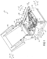
Figure 1 is a front right perspective view of a furniture member having a mechanism for powered combined or independent operation of a leg rest member and a seat back member; -
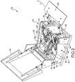
Figure 2 is a right front perspective view of the furniture member ofFigure 1 showing the leg rest member in a fully extended position; -
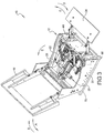
Figure 3 is right front perspective view of the furniture member ofFigure 1 showing the leg rest member in a fully extended position and the seat back member in a fully reclined position; -
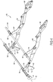
Figure 4 is a right front perspective view of an extended pantograph linkage set of the mechanism ofFigure 1 connected to both a drive rod and a support shaft; -
Figure 5 is a right front perspective view of a portion of the mechanism ofFigure 1 ; -
Figure 6 is a right rear perspective view of the mechanism ofFigure 5 ; -
Figure 5 is a right front perspective view of a portion of the mechanism ofFigure 1 ; -
Figure 6 is a right rear perspective view of the mechanism ofFigure 5 ; -
Figure 7 is a right rear perspective view of a portion of the furniture member ofFigure 1 showing components operated to control seat back member rotation; -
Figure 8 is a right rear perspective view of a drive and swing link portion of the mechanism operated to control leg rest member rotation; -
Figure 9 is a right rear perspective view of a portion of the furniture member ofFigure 1 showing components operated to control leg rest member rotation; -
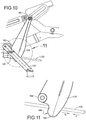
Figure 10 is a right side elevational view of a portion of the mechanism ofFigure 6 ; -
Figure 11 is a right side elevational view of area 11 ofFigure 10 having the tilt swing lever removed for clarity; -
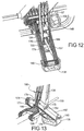
Figure 12 is a front right perspective view of a swing lever and tilt swing lever combination of the mechanism ofFigure 6 ; -
Figure 13 is a right rear perspective view of the swing lever and tilt swing lever combination ofFigure 12 ; -
Figure 14 is a right side elevational view of the furniture member ofFigure 2 having a furniture member right side member removed for clarity; -
Figure 15 is a right side elevational view ofarea 15 ofFigure 14 ; -
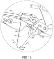
Figure 16 is a right side elevational view modified fromFigure 10 to shown the mechanism in a leg rest extended and full rearward tilt position; -
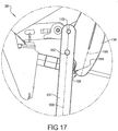
Figure 17 is a right side elevational view ofarea 17 ofFigure 16 ; -
Figure 18 is a right rear perspective view of the fully extended position of the pantograph linkage set in a object contact/release position; and -
Figure 19 is a right rear perspective view ofarea 19 ofFigure 18 . - Corresponding reference numerals indicate corresponding parts throughout the several views of the drawings.
- Example embodiments will now be described more fully with reference to the accompanying drawings.
- Referring to
Figure 1 , afurniture member 10 includes afurniture frame assembly 12 which is rotatably supported with respect to abase member 14. Aseat back member 16 is rotatably connected tofurniture frame assembly 12 and can rotate from a fully upright position in a seat back recline direction "A" or return from a fully reclined position in a seat back return direction "B" toward the fully upright position, or be positioned at any position therebetween.Seat back member 16 is rotatably connected tofurniture frame assembly 12 using oppositely positioned rotational connectors 18 (only one of which is clearly visible in this view).Furniture frame assembly 12 includes afirst side member 20 positioned with respect to an occupant's right hand side for an occupant seated onfurniture member 10, and asecond side member 22 positioned on the occupant's left hand side. Aleg rest member 24 is extensible from a fully stowed position shown in a leg rest extension direction "C" and returnable in a leg rest retraction direction "D" using amechanism 26 which is connected to each of thefurniture frame assembly 12 andbase member 14. Movement of the seat backmember 16 is also controlled at least in the seat back recline direction "A" by operation ofmechanism 26. -
Mechanism 26 includes each of afirst actuator device 28 which is used to control rotation of theseat back member 16, and asecond actuator device 30 which is used to extend or retractleg rest member 24 as well as to permit a tilting motion offurniture frame assembly 12 with respect tobase member 14. The tilting motion offurniture frame assembly 12 is with respect to a rear rotation direction "E" and a forward rotation direction "F". Operation ofsecond actuator device 30 simultaneously controls displacement ofleg rest member 24 as well as tilt rotation offurniture frame assembly 12. For example, asleg rest member 24 is extended in the leg rest extension direction "C",furniture frame assembly 12 is tilted by rotation in the rear rotation direction "E". Opposite rotation ofleg rest member 24 also causes an opposite rotation offurniture frame assembly 12 in the forward rotation direction "F". - First and
second actuator devices rigid tube 32.Rigid tube 32 is fixedly connected to each of the first andsecond side members rigid tube 32. This provides a fixed reference point for operation of either of the first orsecond actuator devices First actuator device 28 is connected to and operates a seat backoperating portion 34 ofmechanism 26. Seat backoperating portion 34 includes each of a first seatback actuation link 35 positioned proximate tofirst side member 20 and a second seatback actuation link 36 positioned proximate tosecond side member 22. Alateral drive member 38, which according to several embodiments is a length of wood material, but can be any suitable material such as metal or plastic, is movably connected with respect tosecond side member 22 and connected by a seat back linkage set 40 to seatback member 16. Displacement oflateral drive member 38 in a drive member powered motion direction "G" by operation offirst actuator device 28 causes a reclining rotation ofseat back member 16 in the seat back recline direction "A". To provide for rotation ofseat back member 16, arotational fastener 42 is used to rotatably connect seat back linkage set 40 to seatback member 16. To structurally stiffenfurniture frame assembly 12, aforward frame member 44 is oriented substantially perpendicular to and is fixedly connected to each of the first andsecond side members frame brace 46, which is positioned in an orientation substantially parallel with respect torigid tube 32 can also be provided, which is also fixedly connected to each of the first andsecond side members - Referring to
Figure 2 , each of the first andsecond actuator devices actuator motor 48, 48' which is connected to and provides energy of operation for anactuator drive member actuator motor 48, 48' for each of the first andsecond actuator devices actuator motor 48, 48' is converted to a linear motion byactuator drive member actuator displacement member 52 is connected to and linearly displaced byactuator drive member 50 and provides for opposing linear motions. Similar to seat back operatingportion 34 which is connected tofirst actuator device 28,second actuator device 30 has a leg rest andtilt operating portion 54 which converts the fore and aft sliding displacement of theactuator displacement member 52 into an axial rotation of adrive rod 56 which is supported by both first andsecond side members rod 56, permitting axial rotation ofdrive rod 56 while providing lateral support by connection of the drive rod stiffening braces 58, 58' to forwardframe member 44. Drive rod stiffening braces 58, 58' therefore permit axial rotation ofdrive rod 56 while limiting or preventing longitudinal bending ofdrive rod 56. Axial rotation ofdrive rod 56 displaces both first and second pantograph linkage sets 60, 62 in the leg rest extension direction "C" which is fixedly connected toleg rest member 24. - To provide additional occupant weight support for the weight of the occupant's legs on
leg rest member 24,mechanism 26 further includes asupport rod 64 which is oriented substantially parallel to driverod 56 and is positioned forward ofdrive rod 56 to provide additional support for first and second pantograph linkage sets 60, 62 in their extended positions.Support rod 64 does not axially rotate but is supported at opposite ends by first andsecond side members free end 66 ofdrive rod 56 can extend partially outward with respect tofirst side member 20. Drive rodfree end 66 can be provided for attachment of a lever (not shown) used for manual rotation ofdrive rod 56 when electrical power is not available for operation of thesecond actuator device 30. - Referring to
Figure 3 ,furniture member 10 can be positioned having the seat backmember 16 in the fully reclined position simultaneously with theleg rest member 24 being moved to the fully extended position by simultaneous operation of both the first andsecond actuator devices leg rest member 24 extends in the leg rest extension direction "C",furniture frame assembly 12 is tilted rearwardly with respect to the rear rotation direction "E". In a furniture member frame tilt position, a frame assemblyfront corner 68 is elevated with respect to a frame assemblyrear corner 70 offurniture frame assembly 12 when theleg rest member 24 is in any extended position with respect toforward frame member 44.Mechanism 26 offurniture member 10 can also be operated by energizing only one of the first orsecond actuator devices member 16 or extendleg rest member 24. -
Furniture member 10 further provides the option for the operator to return the seat backmember 16 to the fully upright position by independent powered operation offirst actuator device 28, causing seat backmember 16 to rotate in the seat back return direction "B" while theleg rest member 24 is still in any extended position. Conversely, the operator can also return theleg rest member 24 from any extended position to the fully stowed or retracted position by movement in the leg rest retraction direction "D" by independent operation ofsecond actuator device 30, while the seat backmember 16 is retained in the upright or any reclined position. This optional operation of either the seat backmember 16 or theleg rest member 24 is permitted by the independent connection and operation of the first andsecond actuator devices - Referring to
Figure 4 , features relating to thedrive rod 56,support rod 64, and each of the first and second pantograph linkage sets 60, 62 are shown in greater detail, having the first and second pantograph linkage sets 60, 62 in their fully extended positions. To extend the first and second pantograph linkage sets 60, 62,drive rod 56 is rotated in a first drive rod rotation direction "H" which is counterclockwise as viewed inFigure 4 . This counterclockwise rotation ofdrive rod 56 is caused by a counterclockwise rotation of first and second leg rest drive links 74, 74'. It is noted that each of the components connected to and operating the first and second pantograph linkage sets 60, 62 are substantially opposite and mirror image configurations of each other; therefore, the following discussion of the connections and operation of first pantograph linkage set 60 applies equally to second pantograph linkage set 62. The first legrest drive link 74 is substantially triangular shaped and includes adrive link flange 76 which is fixedly connected to driverod 56. Axial rotation ofdrive rod 56 therefore co-rotates the legrest drive link 74. Rotation of first legrest drive link 74 in the first drive rod rotation direction "H" also co-rotates aswing link 78 which is rotatably connected to first pantograph linkage set 60. It should be evident that an opposite axial rotation ofdrive rod 56 in a clockwise rotation direction will cause retraction of the first and second pantograph linkage sets 60, 62. - A
contact flange 80 of legrest drive link 74, which is oriented substantially perpendicular to a triangular shaped body of first legrest drive link 74, directly contacts swinglink 78 to cause rotation ofswing link 78 thereby matching the first drive rod rotation direction "H".Swing link 78 is not directly connected to first legrest drive link 74, but is induced to rotate when pushed bycontact flange 80. Contact betweenswing link 78 and first legrest drive link 74 is normally maintained by a biasing force created by a biasingmember 82 which is connected to both first legrest drive link 74 andswing link 78.Swing link 78 is rotatably connected to driverod 56, and is therefore permitted to freely rotate with respect to driverod 56. - A
pantograph connecting link 84 is rotatably connected to first pantograph linkage set 60 and rotatably connected to supportrod 64. The weight of the occupant's legs carried by the leg rest member (not shown in this view) is therefore distributed through bothswing link 78 andpantograph connecting link 84. This distributes the occupant's leg weight to each of thedrive rod 56 and thesupport rod 64. First pantograph linkage set 60 further includes a leg restrotational fitting 86 acting as a bearing to permit reduced friction rotation ofpantograph connecting link 84 with respect to supportrod 64. A legrest connecting flange 88 is provided at a free end of first pantograph linkage set 60 which is used as a mounting surface forleg rest member 24 shown and described in reference toFigure 1 . - Referring to
Figure 5 , the first andsecond actuator devices rigid tube 32 using either a firstactuator mount bracket 90 or a secondactuator mount bracket 92. A firstactuator mount pin 94 permitsfirst actuator device 28 to rotate with respect to firstactuator mount bracket 90. Similarly, a secondactuator mount pin 96 permitssecond actuator device 30 to rotate with respect to secondactuator mount bracket 92. According to several embodiments, a driverod support brace 98 is connected to firstactuator mount bracket 90 and also to driverod 56 to provide additional support fordrive rod 56. - Further components of seat back operating
portion 34 include aswing connection tube 100 which is substantially U-shaped and is freely rotatably supported ondrive rod 56.Swing connection tube 100 is rotated by extension or retraction of a firstactuator extension shaft 102, which is extendable or retractable from actuator displacement member 52' during operation offirst actuator device 28.Swing connection tube 100 includes afirst tube arm 104 oriented substantially parallel with respect to asecond tube arm 106.First tube arm 104 is rotatably connected to driverod 56 using afirst arm bracket 108. Similarly,second tube arm 106 is rotatably connected to driverod 56 using asecond arm bracket 110. First seat backactuation link 35 is rotatably connected tofirst tube arm 104 using a first spin fitting 112. Similarly, a second spin fitting 114 is used to rotatably connect second seat backactuation link 36 tosecond tube arm 106. Rotation ofswing connection tube 100 with respect to drive rod axis ofrotation 72 therefore displaces first and second seat back actuation links 35, 36 which are individually connected to and displace each of afirst mount plate 116 and asecond mount plate 118.First mount plate 116 includes anelongated slot 120 which slidably receivessupport rod 64. Similarly,second mount plate 118 includes anelongated slot 122 to also slidably receivesupport rod 64.Support rod 64 can therefore be substantially fixed in position with respect to driverod 56 even as the first andsecond mount plates swing connection tube 100. - With continuing reference to
Figures 5 and1 , thelateral drive member 38 is fixed to aplate flange 124 extending fromfirst mount plate 116. The displacement ofsecond mount plate 118 in a forward or rearward direction by rotation ofswing connection tube 100 therefore longitudinally displaceslateral drive member 38, which thereby rotates the seat backmember 16 via seat back linkage set 40.Support rod 64, which is fixed in position, extends through the individualelongated slots elongated slots second mount plates - The
second actuator device 30 further includes a secondactuator extension shaft 126 which extends in a forward or rearward general direction by operation ofsecond actuator device 30. Secondactuator extension shaft 126 is connected to adrive toggle connector 128. Drivetoggle connector 128 is connected to a drive toggleconnector extension rod 130 such that drive toggleconnector extension rod 130 is co-linearly displaced during displacement ofdrive toggle connector 128. Adrive toggle 132 is connected to driverod 56 and rotatably connected to drivetoggle connector 128. Extension ofdrive toggle connector 128 during extension or retraction of secondactuator extension shaft 126 rotates drivetoggle 132, thereby axially rotatingdrive rod 56. Becausedrive rod 56 is substantially square or rectangular in cross-sectional shape, the geometry of the connectors used betweendrive toggle 132 and driverod 56 are also square or rectangular in shape, matching the geometry ofdrive rod 56. - A
swing lever 134 is rotatably connected to supportrod 64 at a swinglever rotation end 136 such thatswing lever 134 is freely rotatable with respect to supportrod 64. During powered operation ofsecond actuator device 30,drive toggle connector 128 contacts swinglever 134 and thereby rotatesswing lever 134 with respect to supportrod 64. Atilt swing lever 137 is connected tobase member 14 using a tiltswing mount bracket 138 and a tiltswing rotation pin 140.Tilt swing lever 137 is rotatably connected to swinglever 134. Rotation ofswing lever 134 causes an oppositely directed rotation oftilt swing lever 137. A force exerted bydrive toggle connector 128 to swinglever 134 andtilt swing lever 137 causesfurniture frame assembly 12 to rotate (tilt) during extension of the leg rest assembly (only partially shown with respect to second pantograph linkage set 62). Becausesupport rod 64 is substantially fixed in position with respect tofurniture frame assembly 12, as the combination ofswing lever 134 andtilt swing lever 137 rotate by displacement ofdrive toggle connector 128, thetilt swing lever 137 and theswing lever 134 will rotate into a substantially co-linear orientation as will be described in greater detail in reference toFigures 16 and17 . This linear alignment creates a lifting force pushing upwardly and forwardly onsupport rod 64, causing rear rotation or tilt offurniture frame assembly 12. - Operation of
first actuator device 28 causes rotation ofswing connection tube 100 to displace the first andsecond mount plates drive rod 56. Rotation ofdrive rod 56 only occurs during operation ofsecond actuator device 30 to both extend the first and second pantograph linkage sets 60, 62 and to produce the rearward tilt offurniture frame assembly 12. Thesupport rod 64 is not axially rotatable with respect to a support rodlongitudinal axis 142 howeversupport rod 64 is displaceable by the rotation ofswing lever 134 andtilt swing lever 137 to produce the rearward tilt offurniture frame assembly 12. - Referring to
Figure 6 , the distinct operational portions ofmechanism 26 for controlling seat back rotation or leg rest and tilt movement are more clearly visible by removal of thefurniture frame assembly 12.First actuator device 28 operates to rotateswing connection tube 100 which forwardly displaces each of the first and second seat back actuation links 35, 36. Forward displacement of the first and second seat back actuation links 35, 36, in turn, forwardly and upwardly displace the first andsecond mount plates first actuator device 28 reverses the rotation ofswing connection tube 100, thereby retracting the first and second seat back actuation links 35, 36 andsecond mount plates second mount plates support rod 64 such thatsupport rod 64 remains in position with respect to support rodlongitudinal axis 142 during the displacement of first orsecond mount plates - With continuing reference to
Figures 6 and1-3 , independent operation ofsecond actuator device 30 displaces theactuator displacement member 52 thereby rotatingdrive toggle connector 128 and drivetoggle 132. Rotation ofdrive toggle 132 axially rotates driverod 56, thereby co-rotating both legrest drive link 74 andswing link 78. First pantograph linkage set 60 is not shown for clarity, however it is noted that rotation of both leg rest drive links 74, 74' andswing links second actuator device second actuator devices leg rest member 24 or the seat backmember 16 can therefore be selected by the occupant independent of the other. - The
tilt swing lever 137 is rotatably connected to theswing lever 134 using a tiltswing lever pin 144. Tiltswing lever pin 144 therefore displaces both theswing lever 134 andsupport rod 64 whentilt swing lever 137 is rotated. In the free position shown fortilt swing lever 137,tilt swing lever 137 is freely disposed on drive toggleconnector extension rod 130 when the first and second pantograph linkage sets 60, 62 are substantially in their retracted positions. Limited extension of the first and second pantograph linkage sets 60, 62 can occur beforedrive toggle connector 128 contacts tiltswing lever 137. Continued contact betweendrive toggle connector 128 andtilt swing lever 137 will thereafter rotatetilt swing lever 137 andswing lever 134, and cause displacement ofsupport rod 64, thereby creating the tilt position ofmechanism 26. This will be shown and described in greater detail in reference toFigures 14-17 . -
Rotational bearings 146 are provided for each of the first andsecond arm brackets 108, 110 (onlysecond arm bracket 110 is clearly visible in this view). Therotational bearings 146 permit the axial rotation ofdrive rod 56 with respect to drive rod axis ofrotation 72 independent of the rotation ofswing connection tube 100. This allows the rotational axis ofswing connection tube 100 to also be maintained coaxial with respect to drive rod axis ofrotation 72 without requiring co-rotation ofswing connection tube 100 asdrive rod 56 rotates. - Referring to
Figure 7 , in addition to the capability ofmechanism 26 to provide for leg rest extension and retraction and seat back rotation,mechanism 26 further provides for a rocking motion offurniture frame assembly 12 with respect tobase member 14 by manual force/weight distribution of the occupant offurniture member 10, as commonly known. This rotation or rocking motion offurniture frame assembly 12 can be controlled using an opposed set ofrocker spring assemblies rocker spring assembly 148' is clearly visible in this view). Therocker spring assemblies second side members base member 14. The axis of rotation for the rocking motion offurniture frame assembly 12 with respect tobase member 14 is therefore determined by the position of therocker spring assemblies furniture frame assembly 12 occurs with respect to a rearward rocking direction "J" and an opposite forward rocking direction "K". These rocking direction motions are independent of rear and forward rotation directions "E", "F" because the rear and forward rotation directions "E", "F" are oriented with respect to drive rod axis ofrotation 72. - As further shown in
Figure 7 , to return the seat backmember 16 from the fully reclined to the upright position,first actuator device 28 is operated to retract firstactuator extension shaft 102 with respect to actuator displacement member 52'. Because firstactuator extension shaft 102 is rotatably connected to a firstactuator connecting bracket 150, which is also connected to swingconnection tube 100, this retraction of firstactuator extension shaft 102 rotatesswing connection tube 100 in a swing rotation direction "L" with respect to drive rod axis ofrotation 72. Again and as previously noted, rotation ofswing connection tube 100 in the swing rotation direction "L" does not result in an axial rotation ofdrive rod 56. Once the firstactuator extension shaft 102 is fully retracted with respect to actuator displacement member 52', the weight of the occupant seated onfurniture frame assembly 12 also assists in retractinglateral drive member 38 in a direction opposite to drive member powered motion direction "G", thereby permitting the rotation of seat backmember 16 away from the fully retracted and back to the fully forward position. The weight of the occupant offurniture member 10, as well as any force provided by the occupant, therefore assists in the return of seat backmember 16 to the upright position instead of this rotation being an entirely powered operation. - With the first and second pantograph linkage sets 60, 62 positioned in the fully retracted positions (only second pantograph linkage set 62 is clearly visible in this view), the first and second pantograph linkage sets 60, 62 are each received in an individual one of a first
pantograph clearance aperture 152 or a secondpantograph clearance aperture 154. The first and secondpantograph clearance apertures forward frame member 44. Whenleg rest member 24 is positioned in the stowed position,leg rest member 24 contactsforward frame member 44. The first and secondpantograph clearance apertures leg rest member 24 throughforward frame member 44 in any position ofleg rest member 24. - Referring to
Figure 8 , the legrest drive link 74 is shown in the position corresponding to a fully retracted position of the first and second pantograph linkage sets 60, 62 (only first pantograph linkage set 60 is shown in this view). Asdrive rod 56 is axially rotated in the first drive rod rotation direction "H", legrest drive link 74 is also co-rotated in the first drive rod rotation direction "H". Thecontact flange 80 of legrest drive link 74 provides direct contact between legrest drive link 74 and swing link 78 at anedge face 156 ofswing link 78. This direct contact causes simultaneous rotation ofswing link 78 as legrest drive link 74 rotates in the first drive rod rotation direction "H". As previously noted,swing link 78 is freely rotationally positioned with respect to driverod 56 and therefore does not directly rotate in response to rotation ofdrive rod 56. Asswing link 78 is directed to rotate bycontact flange 80, arotational fastener 158 connectingswing link 78 to alink connecting end 160 of first pantograph linkage set 60 transfers the rotational motion ofswing link 78 to a forward translation oflink connecting end 160 and therefore to first pantograph linkage set 60. - Referring to
Figure 9 and again toFigure 8 , legrest drive link 74 is shown following rotation ofdrive rod 56 in the first drive rod rotation direction "H", causing full extension of both first and second pantograph linkage sets 60, 62. At this time, legrest drive link 74 is rotated greater than 90 degrees and approximately 110 degrees with respect to its orientation in the leg rest fully retracted position shown and described inFigure 8 . As previously noted, in addition to the support provided for the occupant's leg weight byswing links pantograph connecting links 84, 84' also distribute a portion of the occupant's leg weight to supportrod 64. The first and secondpantograph clearance apertures forward frame member 44, provide clearance for maximum extension of first and second pantograph linkage sets 60, 62. Rotation ofdrive rod 56 in the first drive rod rotation direction "H" results from axial displacement in a substantially forward direction of secondactuator extension shaft 126 which is displaced by operation ofsecond actuator device 30. This displacement of secondactuator extension shaft 126 causes rotation ofdrive toggle connector 128 and drivetoggle 132, which is directly connected to driverod 56. As previously noted, extension or retraction of first and second pantograph linkage sets 60, 62 occurs independently of any motion imparted by operation offirst actuator device 28. - Referring to
Figure 10 , arotational pin 162 is provided to rotatably connectswing lever 134 to tiltswing lever 137. As previously noted,swing lever 134 is rotatably connected to supportrod 64. The position shown forswing lever 134, with respect to drive toggleconnector extension rod 130, permits free rotational displacement ofswing lever 134 with respect to drive toggleconnector extension rod 130. In this position, drivetoggle connector 128 is spaced fromswing lever 134, allowing free rotation of bothswing lever 134 andtilt swing lever 137 without contact from and therefore in a non-powered manner with respect to drivetoggle connector 128. The free rotation positions ofswing lever 134 andtilt swing lever 137 also permit rocking motion offurniture member 10. - Referring to
Figure 11 and again toFigure 10 ,swing lever 134 includes apin aperture 164 which receives therotational pin 162.Swing lever 134 also includes abulbous end 166 having acurved end face 168.Curved end face 168 is generally convex in shape and is positioned during operation predominantly below drive toggleconnector extension rod 130. In the free position ofswing lever 134 whereindrive toggle connector 128 is not in contact withcurved end face 168, thebulbous end 166 ofswing lever 134 is free to displace in either of a first swing lever sliding direction "N" or an opposite second swing lever sliding direction "P" asswing lever 134 rotates with respect to supportrod 64. This sliding motion in either of the first or second swing lever sliding directions "N", "P" permits rocking motion offurniture member 10 while maintaining drive toggleconnector extension rod 130 sliding contact withswing lever 134 in all rotated positions ofswing lever 134. Drive toggleconnector extension rod 130 acts as a guide to maintainswing lever 134 in a position forcurved end face 168 to be contacted bydrive toggle connector 128, shown and described in better detail in reference toFigures 16 and17 , for powered rotation ofswing lever 134. - Referring to
Figure 12 and again toFigures 10-11 ,swing lever 134 includes arod clearance aperture 170 to allow the free sliding motion of drive toggleconnector extension rod 130 with respect toswing lever 134 asswing lever 134 rotates. Alongitudinal cavity 171 is also provided intilt swing lever 137, which receivesbulbous end 166 ofswing lever 134, to provide further support and sliding guidance for relative displacement betweenbulbous end 166 andtilt swing lever 137. This maintains alignment betweenswing lever 134 andtilt swing lever 137 during rotation. - Referring to
Figure 13 and again toFigure 12 , according to several embodiments tiltswing lever 137 has a substantially U-shape and includes opposed first andsecond lever arms Longitudinal cavity 171 is created between first andsecond lever arms second lever arms lever connecting member 176. The tiltswing rotation pin 140 is slidably received throughlever connecting member 176. In addition tolever connecting member 176,tilt swing lever 137 further includes alever post 178 which spans opposite ends of first andsecond lever arms lever connecting member 176.Lever post 178 creates a positive point of contact when contacting aswing lever face 180 ofswing lever 134 to establish a maximum rotated position oftilt swing lever 137 andswing lever 134. - Referring to
Figure 14 ,mechanism 26 is shown at the fully extended position of first and second pantograph linkage sets 60, 62 and also at the point of contact betweendrive toggle connector 128 andswing lever 134. To reach this position,second actuator device 30 is operated, thereby axially extending secondactuator extension shaft 126 in an extension shaft direction of extension "Q". Up until the point of contact is reached betweendrive toggle connector 128 andswing lever 134, thefurniture frame assembly 12 is free to rock in either of the rearward or forward rocking directions "J", "K" with respect tobase member 14. Immediately upon contact betweendrive toggle connector 128 andswing lever 134, further free rocking motion offurniture frame assembly 12 is precluded. - Referring to
Figure 15 and again toFigure 14 , secondactuator extension shaft 126 is rotatably connected to drivetoggle connector 128 using a pinned connection through aclevis 182. Drivetoggle connector 128 is fixedly connected to drive toggleconnector extension rod 130, therefore extension of secondactuator extension shaft 126 co-extensively displaces each ofdrive toggle connector 128 and drive toggleconnector extension rod 130. As this displacement occurs, thecurved end face 168 ofdrive toggle connector 128 is brought into direct contact withswing lever 134. Further subsequent extension of secondactuator extension shaft 126 in extension shaft direction of extension "Q" causes a combined and oppositely directed rotation ofswing lever 134 which rotates with respect to supportrod 64, andtilt swing lever 137 which rotates with respect to tiltswing rotation pin 140. The axis of common rotation betweenswing lever 134 andtilt swing lever 137 is with respect torotational pin 162. - Referring to
Figure 16 and again toFigure 15 , during extension of secondactuator extension shaft 126 in the extension shaft direction of extension "Q"curved end face 168 ofbulbous end 166 contacts a secondcurved end face 184 ofdrive toggle connector 128. Becausetilt swing lever 137 is rotatably connected using tiltswing rotation pin 140 to tiltswing mount bracket 138, and tiltswing mount bracket 138 is fixedly connected tobase member 14, a clockwise rotation oftilt swing lever 137 causes a corresponding counterclockwise rotation ofswing lever 134 as viewed inFigure 16 with respect to the axis ofrotational pin 162. Astilt swing lever 137 rotates in the clockwise rotation direction, thetilt swing lever 137 approaches but does not reach co-axial alignment with a longitudinal axis ofswing lever 134. This results in a net displacement in a tilt direction "Z" ofsupport rod 64 because of the connection between swinglever rotation end 136 andsupport rod 64. Displacement in tilt direction "Z" ofsupport rod 64 therefore provides a forward and upward motion of thefront corner 68 offurniture frame assembly 12 and a rearward rotational lowering of the frame assemblyrear corner 70 as shown and described in reference toFigure 3 . The weight of the occupant is therefore partially supported in the tilt position byswing lever 134,tilt swing lever 137, and rotational pin162. Because the leg rest assembly can be in its fully extended position during this tilt motion, theleg rest member 24 is further elevated with respect to a floor or planar surface upon whichbase member 14 is supported. - Referring to
Figure 17 and again toFigure 16 , to reduce friction betweencurved end face 168 and secondcurved end face 184 during rotation, these two curved surfaces share a substantially corresponding geometry. At the tilt position ofmechanism 26, a tilt swing leverlongitudinal axis 186 is closely but not co-axially aligned with respect to a swing leverlongitudinal axis 188 to prevent reaching a locking or over-center position of swing leverlongitudinal axis 188. - Referring to
Figure 18 ,mechanism 26 is also provided with a release capability such that if anobject 190 is encountered by either theleg rest member 24 or either of the first or second pantograph linkage sets 60, 62 when theleg rest member 24 is returned in the leg rest retraction direction "D",swing link 78 will release from its contact position with legrest drive link 74. Driverod 56 will continue its axial rotation with respect to a second drive rod rotation direction "R" together with legrest drive link 74 while swing link 78 rotatably separates with respect to contactflange 80 of legrest drive link 74. This permits theleg rest member 24 and each of the first and second pantograph linkage sets 60, 62 to remain substantially in the extended or partially extended position and in contact with theobject 190 as the powered operation or rotation ofdrive rod 56 continues. Afterswing link 78 releases from legrest drive link 74, only the biasing force of biasingmember 82 acts to retractleg rest member 24. This permits the subsequent lifting ofleg rest member 24 by manual displacement in the leg rest extension direction "C" to removeobject 190 although the legrest drive link 74 may have continued its further rotation due to rotation ofdrive rod 56. - With continued reference to
Figures 1-19 ,furniture member mechanism 26 for power combined and independent seat back and leg rest motion includesfirst actuator device 28 electrically operated to displace first and second seat back actuation links 35, 36 which are connected to and operate to rotate seat backmember 16 between an upright position (Figure 2 ) and a fully reclined position (Figure 3 ). Pantograph linkage set 60, 62 is connected toleg rest member 24. The pantograph linkage set 60, 62 is at least partially supported in an extended position by rotational contact withsupport rod 64.Second actuator device 30 is identical to thefirst actuator device 28 and is electrically operated to axially rotatedrive rod 56 connected to at least one legrest drive link 74, 74'. The legrest drive link 74, 74' is connected to and displaces the pantograph linkage set 60, 62 between stowed (Figure 1 ) and extended (Figure 2 ) positions. Theswing lever 134 is rotatably connected to thesupport rod 64 and rotated during operation of thesecond actuator device 30 to extend the pantograph linkage set 60, 62. Theswing lever 134 in a fully rotated position displaces thesupport rod 64 thereby creating a furniture member tilt position (Figure 3 ). -
Mechanisms 26 of the present disclosure offer several advantages. By separating the action of rotating seat backmember 16 from the action of extendingleg rest member 24 through the use of independently operated first andsecond actuator devices member 16 can be moved independently with respect toleg rest member 24. By further including a tilt control forfurniture member 10 with thesecond actuator device 30, automatic tilt is provided whenleg rest member 24 is extended. The provision of first andsecond actuator devices furniture member 10 to rock provides full rocking, seat back rotation, and independent leg rest extension operations in a single mechanism. - The foregoing description of the embodiments has been provided for purposes of illustration and description. It is not intended to be exhaustive or to limit the disclosure. Individual elements or features of a particular embodiment are generally not limited to that particular embodiment, but, where applicable, are interchangeable and can be used in a selected embodiment, even if not specifically shown or described. The same may also be varied in many ways. Such variations are not to be regarded as a departure from the disclosure, and all such modifications are intended to be included within the scope of the disclosure.
Claims (3)
- A furniture member mechanism (26) for power combined and independent seat back and leg rest motion, comprising:a first actuator device (28) electrically operated to displace first and second seat back actuation links (35, 36) connected to and operating to rotate a seat back member (16) between an upright position and a fully reclined position;a pantograph linkage set (60, 62) connected to a leg rest member (24), the pantograph linkage set at least partially supported in an extended position by rotational contact with a support rod (64);a second actuator device (30) identical to the first actuator device and electrically operated to axially rotate a drive rod (56) connected to at least one drive link (74, 74'), the drive link connected to and displacing the pantograph linkage set between a stowed and the extended positions;a swing lever (134) rotatably connected to the support rod and rotated during operation of the second actuator device to extend the pantograph linkage set, the swing lever in a fully rotated position displacing the support rod creating a furniture member tilt position;a bulbous end (166) of the swing lever having a first curved end face (168) defining a convex shape; anda drive toggle connector (128) connected to the second actuator device, the drive toggle connector including a second curved end face (184) having a geometry defining a concave shape, the concave shape corresponding to the convex shape such that a longitudinal displacement of the drive toggle connector causes rotation of the swing lever where the first and second curved end faces contact each other.
- The furniture member mechanism (26) for power combined and independent seat back and leg rest motion of Claim 1, further including:a drive toggle (132) connected to and co-rotatable with the drive rod (56) and rotatably connected to the drive toggle connector (128), rotation of the drive toggle connector acting to rotate the drive toggle and thereby to axially rotate the drive rod; andan actuator extension shaft (126) extended or retracted by operation of the second actuator device (30), the actuator extension shaft rotatably connected to the drive toggle connector.
- The furniture member mechanism (26) for power combined and independent seat back and leg rest motion of Claim 1, further including:an extension rod (130) freely extending from the drive toggle connector (128); anda rod clearance aperture (170) created proximate the bulbous end (166) of the swing lever (134), the extension rod slidably extending through the rod clearance aperture to maintain the first curved end face (168) of the swing lever in alignment with the second curved end face of the drive toggle connector prior to contact between the first and second curved end faces.
Applications Claiming Priority (3)
| Application Number | Priority Date | Filing Date | Title |
|---|---|---|---|
| US13/229,149 US8608240B2 (en) | 2011-09-09 | 2011-09-09 | Mechanism and chair for powered combined and independent seat back and leg rest motion |
| PCT/US2012/052090 WO2013036388A1 (en) | 2011-09-09 | 2012-08-23 | Mechanism and chair for powered combined and independent seat back and leg rest motion |
| EP12830018.3A EP2753213B1 (en) | 2011-09-09 | 2012-08-23 | Furniture member mechanism |
Related Parent Applications (2)
| Application Number | Title | Priority Date | Filing Date |
|---|---|---|---|
| EP12830018.3A Division-Into EP2753213B1 (en) | 2011-09-09 | 2012-08-23 | Furniture member mechanism |
| EP12830018.3A Division EP2753213B1 (en) | 2011-09-09 | 2012-08-23 | Furniture member mechanism |
Publications (2)
| Publication Number | Publication Date |
|---|---|
| EP3047758A1 EP3047758A1 (en) | 2016-07-27 |
| EP3047758B1 true EP3047758B1 (en) | 2018-08-01 |
Family
ID=47829181
Family Applications (2)
| Application Number | Title | Priority Date | Filing Date |
|---|---|---|---|
| EP12830018.3A Active EP2753213B1 (en) | 2011-09-09 | 2012-08-23 | Furniture member mechanism |
| EP16158567.4A Not-in-force EP3047758B1 (en) | 2011-09-09 | 2012-08-23 | Mechanism and chair for power combined and independent seat back and leg rest motion |
Family Applications Before (1)
| Application Number | Title | Priority Date | Filing Date |
|---|---|---|---|
| EP12830018.3A Active EP2753213B1 (en) | 2011-09-09 | 2012-08-23 | Furniture member mechanism |
Country Status (21)
| Country | Link |
|---|---|
| US (1) | US8608240B2 (en) |
| EP (2) | EP2753213B1 (en) |
| JP (1) | JP5866017B2 (en) |
| KR (1) | KR101779248B1 (en) |
| CN (1) | CN103796555B (en) |
| AU (2) | AU2012304801B2 (en) |
| BR (1) | BR112014005638A2 (en) |
| CA (1) | CA2841586C (en) |
| DK (1) | DK2753213T3 (en) |
| ES (1) | ES2653934T3 (en) |
| HK (1) | HK1192127A1 (en) |
| MX (4) | MX339214B (en) |
| MY (1) | MY167453A (en) |
| NO (1) | NO2890684T3 (en) |
| PL (1) | PL2753213T3 (en) |
| PT (1) | PT2753213T (en) |
| RS (1) | RS56613B1 (en) |
| SI (1) | SI2753213T1 (en) |
| TW (1) | TWI594715B (en) |
| WO (1) | WO2013036388A1 (en) |
| ZA (1) | ZA201400113B (en) |
Families Citing this family (39)
| Publication number | Priority date | Publication date | Assignee | Title |
|---|---|---|---|---|
| US8991925B2 (en) | 2012-09-12 | 2015-03-31 | La-Z-Boy Incorporated | Furniture member and power lift mechanism |
| CN103584546B (en) * | 2013-09-23 | 2016-01-27 | 浙江永艺家具股份有限公司 | Seat and backrest installation structure thereof |
| EP3060472B1 (en) * | 2013-10-21 | 2018-04-11 | B/E Aerospace, Inc. | Linearly deployable aircraft seat legrest |
| WO2015153902A1 (en) * | 2014-04-03 | 2015-10-08 | Zodiac Seats Us Llc | Integrated deployable leg rest for reclining passenger seats |
| US9277822B1 (en) * | 2014-09-02 | 2016-03-08 | La-Z-Boy Incorporated | Furniture member with powered mechanism providing lift and zero gravity positions |
| MY188697A (en) * | 2014-09-02 | 2021-12-23 | La Z Boy Inc | Furniture member and power recline and lift mechanism |
| US9357847B2 (en) * | 2014-09-26 | 2016-06-07 | Ultra-Mek, Inc. | Reclining seating unit with power actuators |
| US9332844B2 (en) * | 2014-10-08 | 2016-05-10 | Aminach Bedding & Furniture Manufacturing Ltd. | Electrically controlled recliner with independent rocker-limiting mechanism |
| US9603452B2 (en) * | 2014-10-14 | 2017-03-28 | Ultra-Mek, Inc. | Gliding-reclining seating unit with power actuators |
| US9326615B1 (en) * | 2015-02-11 | 2016-05-03 | La-Z-Boy Incorporated | Furniture member with legrest extension |
| US9655450B2 (en) * | 2015-03-17 | 2017-05-23 | La-Z-Boy Incorporated | Wall proximity furniture member reclining mechanism |
| US10092106B2 (en) | 2015-07-14 | 2018-10-09 | La-Z-Boy Incorporated | Recliner and legrest mechanism for a furniture member |
| DE202015103862U1 (en) * | 2015-07-23 | 2016-10-25 | Dewertokin Gmbh | seat fitting |
| EP3143902B2 (en) * | 2015-09-15 | 2023-04-26 | Ciar S.P.A. | Wall hugger recliner |
| CN105394953B (en) * | 2015-12-15 | 2018-06-29 | 中源家居股份有限公司 | Mimicry cradle sofa base device |
| CN105394952B (en) * | 2015-12-15 | 2018-07-27 | 中源家居股份有限公司 | Mimicry swing sofa base device |
| CA3024943A1 (en) * | 2016-05-20 | 2017-11-23 | Magna Exteriors Inc. | Active underbody panel systems |
| US9986835B2 (en) | 2016-09-22 | 2018-06-05 | La-Z-Boy Incorporated | Furniture member having cam tilt mechanism |
| EP3311701B1 (en) | 2016-10-24 | 2018-09-26 | Egoitaliano Srl | Variable height backrest/headrest for an upholstered item of furniture having an electromechanical lift mechanism |
| CN108013633B (en) * | 2016-10-28 | 2022-10-18 | 意高意大利有限责任公司 | Variable height backrest/headrest for upholstered elements of furniture with electromechanical lifting mechanism |
| CN106617858A (en) * | 2016-11-17 | 2017-05-10 | 嘉兴意合机电有限公司 | Electric adjustable seat system for old people |
| US10537178B2 (en) | 2017-04-07 | 2020-01-21 | La-Z-Boy Incorporated | Furniture member having flexible seatback |
| US10568428B2 (en) | 2017-04-07 | 2020-02-25 | La-Z-Boy Incorporated | Furniture member having flexible seatback |
| WO2018211393A1 (en) * | 2017-05-13 | 2018-11-22 | Elio Maurizio Ravaioli | Improved frame for upholstered sofa or chair |
| US10306986B1 (en) | 2017-05-25 | 2019-06-04 | Zhejiang Feili Technology Co., Ltd. | Motorized furniture headrest assembly for seating systems |
| US10750869B2 (en) * | 2017-07-06 | 2020-08-25 | Ashley Furniture Industries, Inc. | Motion furniture mechanism with pre-aligned linkage member |
| US10349748B2 (en) * | 2017-08-11 | 2019-07-16 | Ashley Furniture Industries, Inc. | Torsion activator for motion furniture |
| US11134781B2 (en) | 2017-08-14 | 2021-10-05 | Ashley Furniture Industries, Inc. | Frame structure and assembly method for motion furniture |
| US10524575B2 (en) | 2018-04-16 | 2020-01-07 | La-Z-Boy Incorporated | Furniture member with foldable pawl and ratchet assembly |
| US10820708B2 (en) | 2018-05-18 | 2020-11-03 | La-Z-Boy Incorporated | Furniture member with wall-proximity mechanism and locking trigger |
| US10524574B2 (en) | 2018-05-18 | 2020-01-07 | La-Z-Boy Incorporated | Furniture member with powered wall-proximity mechanism |
| JP7225812B2 (en) * | 2019-01-16 | 2023-02-21 | トヨタ紡織株式会社 | vehicle seat |
| US11259641B2 (en) | 2019-01-25 | 2022-03-01 | L&P Property Management Company | Synchronization of motion furniture with multiple actuators |
| WO2020227658A1 (en) | 2019-05-09 | 2020-11-12 | La-Z-Boy Incorporated | Reclining chaise |
| DE112020003152A5 (en) * | 2019-06-29 | 2022-03-17 | Michael Schuster | SEATING WITH TWIN ENGINE WALLAWAY FUNCTION |
| US10888169B1 (en) * | 2019-07-12 | 2021-01-12 | Dongguan Jackwell Hardware Co., Ltd | Electric sofa frame |
| DE102020107243B4 (en) * | 2020-03-17 | 2024-02-08 | Ciar S.P.A. | Sitting and lying furniture and method for adjusting a sitting and lying furniture |
| KR102440701B1 (en) * | 2020-08-12 | 2022-09-05 | 현대자동차주식회사 | Power leg-rest for vehicle |
| US11197549B1 (en) | 2020-09-28 | 2021-12-14 | La-Z-Boy Incorporated | Wall-proximity furniture member having sync mechanism |
Family Cites Families (56)
| Publication number | Priority date | Publication date | Assignee | Title |
|---|---|---|---|---|
| US3138402A (en) | 1961-11-01 | 1964-06-23 | American Metal Prod | Invalid chair |
| US3302969A (en) | 1965-01-11 | 1967-02-07 | Pontiac Design Corp | Reclining platform rocking chair |
| US3338632A (en) | 1966-02-09 | 1967-08-29 | Carl T Kleinsorge | Reclining chair |
| US3343871A (en) | 1966-03-03 | 1967-09-26 | George H Yates | Automatically operated invalid chair |
| US3588170A (en) | 1969-07-03 | 1971-06-28 | La Z Boy Chair Co | Motor-operated reclining chair |
| US4007960A (en) | 1975-04-30 | 1977-02-15 | Gaffney Edward J | Reclining elevator chair |
| JPS5936537B2 (en) * | 1979-02-21 | 1984-09-04 | 増夫 中山 | chairs, especially massage chairs |
| US4386803A (en) * | 1981-11-05 | 1983-06-07 | Gilderbloom Clarence W | Motorized reclining chair |
| SE449164B (en) | 1984-03-12 | 1987-04-13 | Henning Bergenwall | MOBILE INCLUDING A STAND, ONE SEAT AND RELATIVELY SET SWINGABLE SEAT |
| FR2586914B1 (en) | 1985-09-09 | 1987-12-04 | Erton | REST SEAT WITH INDEPENDENT CONTROLS |
| IT1200176B (en) | 1986-07-18 | 1989-01-05 | Castellini Spa | STRUCTURE FOR ARMCHAIRS WITH SEAT AND MOBILE BACK, IN PARTICULAR FOR DENTAL USE |
| FR2621795A1 (en) * | 1987-10-14 | 1989-04-21 | By Organisation Sarl | Multi-position armchair |
| US4852939A (en) | 1987-10-23 | 1989-08-01 | Orthokinetics, Inc. | Device for converting a recliner chair to a recliner-lift chair |
| US5061010A (en) | 1988-05-20 | 1991-10-29 | La-Z-Boy Chair Co. | Cam guide drive mechanism for power-assisted chairs and the like |
| CA1299989C (en) | 1988-05-20 | 1992-05-05 | Larry P. Lapointe | Recliner chair lift base assembly |
| US5651580A (en) | 1988-05-20 | 1997-07-29 | La-Z-Boy Chair Company | Linear actuation drive mechanism for power-assisted chairs and base therefor |
| US5482350A (en) | 1988-05-20 | 1996-01-09 | La-Z-Boy Chair Company | Linear actuation drive mechanism for power-assisted chairs |
| US5466046A (en) * | 1988-05-20 | 1995-11-14 | La-Z-Boy Chair Co. | Linear actuation drive mechanism for power-assisted chairs |
| US5024486A (en) | 1990-04-03 | 1991-06-18 | Auel Carl C | All-purpose rocking, swiveling, reclining, and lifting chair |
| US5312153A (en) | 1990-07-23 | 1994-05-17 | Ortho-Kinetics, Inc. | Recline lift wall hugger chair |
| US5075906A (en) * | 1990-10-31 | 1991-12-31 | Daniel T. Robbins | Seat lift |
| US5165753A (en) | 1991-01-02 | 1992-11-24 | Henderson Eldred D | Elevator chair apparatus |
| US5222286A (en) | 1991-10-11 | 1993-06-29 | La-Z-Boy Chair Co. | Modular reclining/tilt chair and method of making |
| US5292170A (en) * | 1991-08-06 | 1994-03-08 | La-Z-Boy Chair Co. | Recliner assist apparatus |
| US5992931A (en) | 1991-10-11 | 1999-11-30 | La-Z-Boy Incorporated | Modular power reclining chair |
| US5570927A (en) * | 1991-10-11 | 1996-11-05 | La-Z-Boy Chair Company | Modular wall proximity reclining chair |
| US5366036A (en) * | 1993-01-21 | 1994-11-22 | Perry Dale E | Power stand-up and reclining wheelchair |
| US5435622A (en) * | 1994-05-05 | 1995-07-25 | La-Z-Boy Chair Company | Swivel recliner/rocker chair having preloaded base assembly |
| US5806920A (en) | 1994-11-17 | 1998-09-15 | Blount; Eric D. | Fully reclinable elevator lift chair with ottoman |
| US5730494A (en) | 1995-06-07 | 1998-03-24 | La-Z-Boy Incorporated | Linear actuation drive mechanism for power-assisted chairs |
| US5747965A (en) | 1996-03-12 | 1998-05-05 | La-Z-Boy Incorporated | Battery pack for powered motion furniture |
| US5823621A (en) | 1996-11-12 | 1998-10-20 | Invacare Corporation | Reduced shear assembly for recline seat back of a wheelchair |
| DE29812763U1 (en) | 1998-07-17 | 1998-09-10 | Ferdinand Lusch GmbH & Co. KG, 33649 Bielefeld | Armchair changeable in its seating position by a lifting device |
| US6231120B1 (en) * | 1999-04-23 | 2001-05-15 | L&P Property Management Company | Reclining mechanism and furniture item |
| JP2001178779A (en) | 1999-12-22 | 2001-07-03 | Matsushita Electric Works Ltd | Stand-up assisting chair |
| US6702378B2 (en) | 2001-02-08 | 2004-03-09 | L & P Property Management Company | Lift chair skirt |
| JP2002240598A (en) * | 2001-02-21 | 2002-08-28 | Minebea Co Ltd | Electrically operated seat for vehicle and its adjusting method |
| GB2380399B (en) | 2001-04-03 | 2005-02-02 | Graham Taylor | A powered lift recliner chair |
| DE20106560U1 (en) * | 2001-04-14 | 2002-08-29 | Dewert Antriebs- und Systemtechnik GmbH & Co KG, 32278 Kirchlengern | Seat-recliner armchair adjustable by motor |
| DE20108887U1 (en) * | 2001-05-28 | 2002-10-02 | Flamme, Klaus Peter, Dipl.-Ing., 86916 Kaufering | Double-motor adjustment for fittings with sliding secondary parts for the footrest and back |
| GB0119132D0 (en) | 2001-08-03 | 2001-09-26 | Seminar Components Uk Ltd | Imrovements in and relating to adjustable chairs and beds |
| US6896323B2 (en) | 2003-06-20 | 2005-05-24 | La-Z-Boy Incorporated | Actuation mechanism for reclining chair |
| US6902233B2 (en) | 2003-07-30 | 2005-06-07 | Taiwan Shin Yeh Enterprise Co., Ltd. | Reclining chair with extendible leg rest |
| US6926366B2 (en) * | 2003-10-15 | 2005-08-09 | Midmark Corporation | Universal power table |
| GB0325358D0 (en) | 2003-10-30 | 2003-12-03 | Peter Cook Internat Plc | Powered furniture |
| US6974186B1 (en) * | 2004-07-03 | 2005-12-13 | Horng Jiun Chang | Chair |
| GB2417895B (en) * | 2004-09-13 | 2008-12-17 | Golden Technologies Inc | Lift chair and recliner |
| US7090297B2 (en) | 2004-10-13 | 2006-08-15 | La-Z-Boy Incorporated | Heavy lift chair |
| JP2007068983A (en) * | 2005-08-09 | 2007-03-22 | Katsumi Hakui | Combination bed and reclining chair |
| CN200941924Y (en) * | 2006-07-26 | 2007-09-05 | 喜客来家具寝具部件(深圳)有限公司 | Frame for sofa chair |
| JP4731422B2 (en) | 2006-08-01 | 2011-07-27 | 三洋電機株式会社 | Chair type massage machine |
| JP2008049920A (en) * | 2006-08-25 | 2008-03-06 | Mazda Motor Corp | Movable floor device for automobile |
| US7673933B2 (en) * | 2007-02-15 | 2010-03-09 | Omega Motion L.L.C. | Recliner lift chair with dual motors |
| NO326574B1 (en) * | 2007-03-13 | 2009-01-12 | Sapdesign As | Device by chair with adjustable angle between chair seat and back |
| US7628452B2 (en) * | 2008-02-29 | 2009-12-08 | Shanghai Industries Group, Ltd. | Rocker base |
| CN102133004A (en) * | 2010-01-22 | 2011-07-27 | 刘荣兵 | Massage chair |
-
2011
- 2011-09-09 US US13/229,149 patent/US8608240B2/en active Active
-
2012
- 2012-08-23 RS RS20171189A patent/RS56613B1/en unknown
- 2012-08-23 KR KR1020147005976A patent/KR101779248B1/en active IP Right Grant
- 2012-08-23 MY MYPI2014000639A patent/MY167453A/en unknown
- 2012-08-23 BR BR112014005638A patent/BR112014005638A2/en not_active IP Right Cessation
- 2012-08-23 MX MX2014000860A patent/MX339214B/en active IP Right Grant
- 2012-08-23 CN CN201280041173.7A patent/CN103796555B/en active Active
- 2012-08-23 SI SI201231124T patent/SI2753213T1/en unknown
- 2012-08-23 DK DK12830018.3T patent/DK2753213T3/en active
- 2012-08-23 ES ES12830018.3T patent/ES2653934T3/en active Active
- 2012-08-23 MX MX2015016161A patent/MX342201B/en unknown
- 2012-08-23 WO PCT/US2012/052090 patent/WO2013036388A1/en active Application Filing
- 2012-08-23 EP EP12830018.3A patent/EP2753213B1/en active Active
- 2012-08-23 MX MX2015016162A patent/MX339919B/en unknown
- 2012-08-23 JP JP2014529755A patent/JP5866017B2/en not_active Expired - Fee Related
- 2012-08-23 PT PT128300183T patent/PT2753213T/en unknown
- 2012-08-23 PL PL12830018T patent/PL2753213T3/en unknown
- 2012-08-23 EP EP16158567.4A patent/EP3047758B1/en not_active Not-in-force
- 2012-08-23 MX MX2015016160A patent/MX341878B/en unknown
- 2012-08-23 CA CA2841586A patent/CA2841586C/en active Active
- 2012-08-23 AU AU2012304801A patent/AU2012304801B2/en not_active Ceased
- 2012-09-07 TW TW101132890A patent/TWI594715B/en not_active IP Right Cessation
-
2013
- 2013-07-24 NO NO13750166A patent/NO2890684T3/no unknown
-
2014
- 2014-01-07 ZA ZA2014/00113A patent/ZA201400113B/en unknown
- 2014-06-06 HK HK14105351.6A patent/HK1192127A1/en not_active IP Right Cessation
-
2017
- 2017-11-17 AU AU2017261636A patent/AU2017261636A1/en not_active Abandoned
Also Published As
Similar Documents
| Publication | Publication Date | Title |
|---|---|---|
| EP3047758B1 (en) | Mechanism and chair for power combined and independent seat back and leg rest motion | |
| AU2019201565B2 (en) | Furniture Member With Powered Mechanism Providing Lift And Zero Gravity Positions | |
| AU2011207793B2 (en) | Zero-wall clearance linkage mechanism for high-leg seating unit | |
| CA2864018C (en) | Furniture member power mechanism with selectable lift movement and zero gravity position | |
| US8833844B2 (en) | Power actuated glider furniture member | |
| US9326606B2 (en) | Furniture member power mechanism with zero gravity and rear tilt positions | |
| US7866742B2 (en) | Furniture member head support system | |
| NZ619030B2 (en) | Mechanism and chair for powered combined and independent seat back and leg rest motion |
Legal Events
| Date | Code | Title | Description |
|---|---|---|---|
| PUAI | Public reference made under article 153(3) epc to a published international application that has entered the european phase |
Free format text: ORIGINAL CODE: 0009012 |
|
| AC | Divisional application: reference to earlier application |
Ref document number: 2753213 Country of ref document: EP Kind code of ref document: P |
|
| AK | Designated contracting states |
Kind code of ref document: A1 Designated state(s): AL AT BE BG CH CY CZ DE DK EE ES FI FR GB GR HR HU IE IS IT LI LT LU LV MC MK MT NL NO PL PT RO RS SE SI SK SM TR |
|
| STAA | Information on the status of an ep patent application or granted ep patent |
Free format text: STATUS: REQUEST FOR EXAMINATION WAS MADE |
|
| 17P | Request for examination filed |
Effective date: 20170120 |
|
| RBV | Designated contracting states (corrected) |
Designated state(s): AL AT BE BG CH CY CZ DE DK EE ES FI FR GB GR HR HU IE IS IT LI LT LU LV MC MK MT NL NO PL PT RO RS SE SI SK SM TR |
|
| GRAP | Despatch of communication of intention to grant a patent |
Free format text: ORIGINAL CODE: EPIDOSNIGR1 |
|
| STAA | Information on the status of an ep patent application or granted ep patent |
Free format text: STATUS: GRANT OF PATENT IS INTENDED |
|
| INTG | Intention to grant announced |
Effective date: 20180221 |
|
| GRAS | Grant fee paid |
Free format text: ORIGINAL CODE: EPIDOSNIGR3 |
|
| GRAA | (expected) grant |
Free format text: ORIGINAL CODE: 0009210 |
|
| STAA | Information on the status of an ep patent application or granted ep patent |
Free format text: STATUS: THE PATENT HAS BEEN GRANTED |
|
| AC | Divisional application: reference to earlier application |
Ref document number: 2753213 Country of ref document: EP Kind code of ref document: P |
|
| AK | Designated contracting states |
Kind code of ref document: B1 Designated state(s): AL AT BE BG CH CY CZ DE DK EE ES FI FR GB GR HR HU IE IS IT LI LT LU LV MC MK MT NL NO PL PT RO RS SE SI SK SM TR |
|
| REG | Reference to a national code |
Ref country code: GB Ref legal event code: FG4D |
|
| REG | Reference to a national code |
Ref country code: CH Ref legal event code: EP Ref country code: AT Ref legal event code: REF Ref document number: 1023299 Country of ref document: AT Kind code of ref document: T Effective date: 20180815 |
|
| REG | Reference to a national code |
Ref country code: IE Ref legal event code: FG4D |
|
| REG | Reference to a national code |
Ref country code: DE Ref legal event code: R096 Ref document number: 602012049312 Country of ref document: DE |
|
| REG | Reference to a national code |
Ref country code: NL Ref legal event code: MP Effective date: 20180801 |
|
| REG | Reference to a national code |
Ref country code: LT Ref legal event code: MG4D |
|
| REG | Reference to a national code |
Ref country code: AT Ref legal event code: MK05 Ref document number: 1023299 Country of ref document: AT Kind code of ref document: T Effective date: 20180801 |
|
| PG25 | Lapsed in a contracting state [announced via postgrant information from national office to epo] |
Ref country code: LT Free format text: LAPSE BECAUSE OF FAILURE TO SUBMIT A TRANSLATION OF THE DESCRIPTION OR TO PAY THE FEE WITHIN THE PRESCRIBED TIME-LIMIT Effective date: 20180801 Ref country code: PL Free format text: LAPSE BECAUSE OF FAILURE TO SUBMIT A TRANSLATION OF THE DESCRIPTION OR TO PAY THE FEE WITHIN THE PRESCRIBED TIME-LIMIT Effective date: 20180801 Ref country code: IS Free format text: LAPSE BECAUSE OF FAILURE TO SUBMIT A TRANSLATION OF THE DESCRIPTION OR TO PAY THE FEE WITHIN THE PRESCRIBED TIME-LIMIT Effective date: 20181201 Ref country code: NL Free format text: LAPSE BECAUSE OF FAILURE TO SUBMIT A TRANSLATION OF THE DESCRIPTION OR TO PAY THE FEE WITHIN THE PRESCRIBED TIME-LIMIT Effective date: 20180801 Ref country code: RS Free format text: LAPSE BECAUSE OF FAILURE TO SUBMIT A TRANSLATION OF THE DESCRIPTION OR TO PAY THE FEE WITHIN THE PRESCRIBED TIME-LIMIT Effective date: 20180801 Ref country code: FI Free format text: LAPSE BECAUSE OF FAILURE TO SUBMIT A TRANSLATION OF THE DESCRIPTION OR TO PAY THE FEE WITHIN THE PRESCRIBED TIME-LIMIT Effective date: 20180801 Ref country code: NO Free format text: LAPSE BECAUSE OF FAILURE TO SUBMIT A TRANSLATION OF THE DESCRIPTION OR TO PAY THE FEE WITHIN THE PRESCRIBED TIME-LIMIT Effective date: 20181101 Ref country code: GR Free format text: LAPSE BECAUSE OF FAILURE TO SUBMIT A TRANSLATION OF THE DESCRIPTION OR TO PAY THE FEE WITHIN THE PRESCRIBED TIME-LIMIT Effective date: 20181102 Ref country code: BG Free format text: LAPSE BECAUSE OF FAILURE TO SUBMIT A TRANSLATION OF THE DESCRIPTION OR TO PAY THE FEE WITHIN THE PRESCRIBED TIME-LIMIT Effective date: 20181101 Ref country code: AT Free format text: LAPSE BECAUSE OF FAILURE TO SUBMIT A TRANSLATION OF THE DESCRIPTION OR TO PAY THE FEE WITHIN THE PRESCRIBED TIME-LIMIT Effective date: 20180801 Ref country code: SE Free format text: LAPSE BECAUSE OF FAILURE TO SUBMIT A TRANSLATION OF THE DESCRIPTION OR TO PAY THE FEE WITHIN THE PRESCRIBED TIME-LIMIT Effective date: 20180801 |
|
| PG25 | Lapsed in a contracting state [announced via postgrant information from national office to epo] |
Ref country code: HR Free format text: LAPSE BECAUSE OF FAILURE TO SUBMIT A TRANSLATION OF THE DESCRIPTION OR TO PAY THE FEE WITHIN THE PRESCRIBED TIME-LIMIT Effective date: 20180801 Ref country code: LV Free format text: LAPSE BECAUSE OF FAILURE TO SUBMIT A TRANSLATION OF THE DESCRIPTION OR TO PAY THE FEE WITHIN THE PRESCRIBED TIME-LIMIT Effective date: 20180801 Ref country code: AL Free format text: LAPSE BECAUSE OF FAILURE TO SUBMIT A TRANSLATION OF THE DESCRIPTION OR TO PAY THE FEE WITHIN THE PRESCRIBED TIME-LIMIT Effective date: 20180801 |
|
| REG | Reference to a national code |
Ref country code: DE Ref legal event code: R119 Ref document number: 602012049312 Country of ref document: DE |
|
| REG | Reference to a national code |
Ref country code: CH Ref legal event code: PL |
|
| PG25 | Lapsed in a contracting state [announced via postgrant information from national office to epo] |
Ref country code: LU Free format text: LAPSE BECAUSE OF NON-PAYMENT OF DUE FEES Effective date: 20180823 Ref country code: RO Free format text: LAPSE BECAUSE OF FAILURE TO SUBMIT A TRANSLATION OF THE DESCRIPTION OR TO PAY THE FEE WITHIN THE PRESCRIBED TIME-LIMIT Effective date: 20180801 Ref country code: IT Free format text: LAPSE BECAUSE OF FAILURE TO SUBMIT A TRANSLATION OF THE DESCRIPTION OR TO PAY THE FEE WITHIN THE PRESCRIBED TIME-LIMIT Effective date: 20180801 Ref country code: CZ Free format text: LAPSE BECAUSE OF FAILURE TO SUBMIT A TRANSLATION OF THE DESCRIPTION OR TO PAY THE FEE WITHIN THE PRESCRIBED TIME-LIMIT Effective date: 20180801 Ref country code: CH Free format text: LAPSE BECAUSE OF NON-PAYMENT OF DUE FEES Effective date: 20180831 Ref country code: MC Free format text: LAPSE BECAUSE OF FAILURE TO SUBMIT A TRANSLATION OF THE DESCRIPTION OR TO PAY THE FEE WITHIN THE PRESCRIBED TIME-LIMIT Effective date: 20180801 Ref country code: LI Free format text: LAPSE BECAUSE OF NON-PAYMENT OF DUE FEES Effective date: 20180831 Ref country code: ES Free format text: LAPSE BECAUSE OF FAILURE TO SUBMIT A TRANSLATION OF THE DESCRIPTION OR TO PAY THE FEE WITHIN THE PRESCRIBED TIME-LIMIT Effective date: 20180801 Ref country code: EE Free format text: LAPSE BECAUSE OF FAILURE TO SUBMIT A TRANSLATION OF THE DESCRIPTION OR TO PAY THE FEE WITHIN THE PRESCRIBED TIME-LIMIT Effective date: 20180801 |
|
| REG | Reference to a national code |
Ref country code: BE Ref legal event code: MM Effective date: 20180831 |
|
| PG25 | Lapsed in a contracting state [announced via postgrant information from national office to epo] |
Ref country code: DK Free format text: LAPSE BECAUSE OF FAILURE TO SUBMIT A TRANSLATION OF THE DESCRIPTION OR TO PAY THE FEE WITHIN THE PRESCRIBED TIME-LIMIT Effective date: 20180801 Ref country code: SM Free format text: LAPSE BECAUSE OF FAILURE TO SUBMIT A TRANSLATION OF THE DESCRIPTION OR TO PAY THE FEE WITHIN THE PRESCRIBED TIME-LIMIT Effective date: 20180801 Ref country code: SK Free format text: LAPSE BECAUSE OF FAILURE TO SUBMIT A TRANSLATION OF THE DESCRIPTION OR TO PAY THE FEE WITHIN THE PRESCRIBED TIME-LIMIT Effective date: 20180801 |
|
| PLBE | No opposition filed within time limit |
Free format text: ORIGINAL CODE: 0009261 |
|
| STAA | Information on the status of an ep patent application or granted ep patent |
Free format text: STATUS: NO OPPOSITION FILED WITHIN TIME LIMIT |
|
| 26N | No opposition filed |
Effective date: 20190503 |
|
| GBPC | Gb: european patent ceased through non-payment of renewal fee |
Effective date: 20181101 |
|
| PG25 | Lapsed in a contracting state [announced via postgrant information from national office to epo] |
Ref country code: DE Free format text: LAPSE BECAUSE OF NON-PAYMENT OF DUE FEES Effective date: 20190301 |
|
| PG25 | Lapsed in a contracting state [announced via postgrant information from national office to epo] |
Ref country code: FR Free format text: LAPSE BECAUSE OF NON-PAYMENT OF DUE FEES Effective date: 20181001 Ref country code: SI Free format text: LAPSE BECAUSE OF FAILURE TO SUBMIT A TRANSLATION OF THE DESCRIPTION OR TO PAY THE FEE WITHIN THE PRESCRIBED TIME-LIMIT Effective date: 20180801 Ref country code: BE Free format text: LAPSE BECAUSE OF NON-PAYMENT OF DUE FEES Effective date: 20180831 |
|
| PG25 | Lapsed in a contracting state [announced via postgrant information from national office to epo] |
Ref country code: GB Free format text: LAPSE BECAUSE OF NON-PAYMENT OF DUE FEES Effective date: 20181101 |
|
| PG25 | Lapsed in a contracting state [announced via postgrant information from national office to epo] |
Ref country code: MT Free format text: LAPSE BECAUSE OF NON-PAYMENT OF DUE FEES Effective date: 20180823 |
|
| PG25 | Lapsed in a contracting state [announced via postgrant information from national office to epo] |
Ref country code: TR Free format text: LAPSE BECAUSE OF FAILURE TO SUBMIT A TRANSLATION OF THE DESCRIPTION OR TO PAY THE FEE WITHIN THE PRESCRIBED TIME-LIMIT Effective date: 20180801 |
|
| PG25 | Lapsed in a contracting state [announced via postgrant information from national office to epo] |
Ref country code: PT Free format text: LAPSE BECAUSE OF FAILURE TO SUBMIT A TRANSLATION OF THE DESCRIPTION OR TO PAY THE FEE WITHIN THE PRESCRIBED TIME-LIMIT Effective date: 20180801 |
|
| PG25 | Lapsed in a contracting state [announced via postgrant information from national office to epo] |
Ref country code: HU Free format text: LAPSE BECAUSE OF FAILURE TO SUBMIT A TRANSLATION OF THE DESCRIPTION OR TO PAY THE FEE WITHIN THE PRESCRIBED TIME-LIMIT; INVALID AB INITIO Effective date: 20120823 Ref country code: MK Free format text: LAPSE BECAUSE OF NON-PAYMENT OF DUE FEES Effective date: 20180801 Ref country code: CY Free format text: LAPSE BECAUSE OF FAILURE TO SUBMIT A TRANSLATION OF THE DESCRIPTION OR TO PAY THE FEE WITHIN THE PRESCRIBED TIME-LIMIT Effective date: 20180801 Ref country code: IE Free format text: LAPSE BECAUSE OF NON-PAYMENT OF DUE FEES Effective date: 20180823 |