EP3047357B1 - Determination of a display angle of a display - Google Patents
Determination of a display angle of a display Download PDFInfo
- Publication number
- EP3047357B1 EP3047357B1 EP14846378.9A EP14846378A EP3047357B1 EP 3047357 B1 EP3047357 B1 EP 3047357B1 EP 14846378 A EP14846378 A EP 14846378A EP 3047357 B1 EP3047357 B1 EP 3047357B1
- Authority
- EP
- European Patent Office
- Prior art keywords
- display
- information
- user
- angle
- display angle
- Prior art date
- Legal status (The legal status is an assumption and is not a legal conclusion. Google has not performed a legal analysis and makes no representation as to the accuracy of the status listed.)
- Active
Links
- 230000005484 gravity Effects 0.000 claims description 78
- 230000008859 change Effects 0.000 claims description 71
- 238000000034 method Methods 0.000 claims description 13
- 238000004590 computer program Methods 0.000 claims description 8
- 230000007613 environmental effect Effects 0.000 description 76
- 238000010586 diagram Methods 0.000 description 43
- 230000000007 visual effect Effects 0.000 description 39
- 230000015654 memory Effects 0.000 description 26
- 230000000694 effects Effects 0.000 description 22
- 238000004891 communication Methods 0.000 description 12
- 230000006870 function Effects 0.000 description 12
- 230000004048 modification Effects 0.000 description 11
- 238000012986 modification Methods 0.000 description 11
- 230000003993 interaction Effects 0.000 description 6
- 206010047571 Visual impairment Diseases 0.000 description 5
- 208000029257 vision disease Diseases 0.000 description 5
- 230000004393 visual impairment Effects 0.000 description 5
- 230000008447 perception Effects 0.000 description 4
- 238000012545 processing Methods 0.000 description 4
- 230000005540 biological transmission Effects 0.000 description 3
- 230000001419 dependent effect Effects 0.000 description 3
- 239000011159 matrix material Substances 0.000 description 3
- 238000010295 mobile communication Methods 0.000 description 3
- 238000012546 transfer Methods 0.000 description 3
- 230000008901 benefit Effects 0.000 description 2
- 230000003287 optical effect Effects 0.000 description 2
- 238000004091 panning Methods 0.000 description 2
- 230000002093 peripheral effect Effects 0.000 description 2
- 230000007704 transition Effects 0.000 description 2
- 206010041349 Somnolence Diseases 0.000 description 1
- 230000003190 augmentative effect Effects 0.000 description 1
- 230000001413 cellular effect Effects 0.000 description 1
- 238000013461 design Methods 0.000 description 1
- 238000005516 engineering process Methods 0.000 description 1
- 230000006855 networking Effects 0.000 description 1
- 238000012634 optical imaging Methods 0.000 description 1
- 230000005043 peripheral vision Effects 0.000 description 1
- 238000009877 rendering Methods 0.000 description 1
- 238000005096 rolling process Methods 0.000 description 1
- 230000011664 signaling Effects 0.000 description 1
Images


Classifications
-
- G—PHYSICS
- G06—COMPUTING; CALCULATING OR COUNTING
- G06T—IMAGE DATA PROCESSING OR GENERATION, IN GENERAL
- G06T3/00—Geometric image transformation in the plane of the image
- G06T3/60—Rotation of a whole image or part thereof
-
- G—PHYSICS
- G06—COMPUTING; CALCULATING OR COUNTING
- G06F—ELECTRIC DIGITAL DATA PROCESSING
- G06F1/00—Details not covered by groups G06F3/00 - G06F13/00 and G06F21/00
- G06F1/16—Constructional details or arrangements
- G06F1/1613—Constructional details or arrangements for portable computers
- G06F1/1626—Constructional details or arrangements for portable computers with a single-body enclosure integrating a flat display, e.g. Personal Digital Assistants [PDAs]
-
- G—PHYSICS
- G06—COMPUTING; CALCULATING OR COUNTING
- G06F—ELECTRIC DIGITAL DATA PROCESSING
- G06F1/00—Details not covered by groups G06F3/00 - G06F13/00 and G06F21/00
- G06F1/16—Constructional details or arrangements
- G06F1/1613—Constructional details or arrangements for portable computers
- G06F1/163—Wearable computers, e.g. on a belt
-
- G—PHYSICS
- G06—COMPUTING; CALCULATING OR COUNTING
- G06F—ELECTRIC DIGITAL DATA PROCESSING
- G06F1/00—Details not covered by groups G06F3/00 - G06F13/00 and G06F21/00
- G06F1/16—Constructional details or arrangements
- G06F1/1613—Constructional details or arrangements for portable computers
- G06F1/1633—Constructional details or arrangements of portable computers not specific to the type of enclosures covered by groups G06F1/1615 - G06F1/1626
- G06F1/1637—Details related to the display arrangement, including those related to the mounting of the display in the housing
-
- G—PHYSICS
- G06—COMPUTING; CALCULATING OR COUNTING
- G06F—ELECTRIC DIGITAL DATA PROCESSING
- G06F1/00—Details not covered by groups G06F3/00 - G06F13/00 and G06F21/00
- G06F1/16—Constructional details or arrangements
- G06F1/1613—Constructional details or arrangements for portable computers
- G06F1/1633—Constructional details or arrangements of portable computers not specific to the type of enclosures covered by groups G06F1/1615 - G06F1/1626
- G06F1/1684—Constructional details or arrangements related to integrated I/O peripherals not covered by groups G06F1/1635 - G06F1/1675
- G06F1/1694—Constructional details or arrangements related to integrated I/O peripherals not covered by groups G06F1/1635 - G06F1/1675 the I/O peripheral being a single or a set of motion sensors for pointer control or gesture input obtained by sensing movements of the portable computer
-
- G—PHYSICS
- G06—COMPUTING; CALCULATING OR COUNTING
- G06F—ELECTRIC DIGITAL DATA PROCESSING
- G06F3/00—Input arrangements for transferring data to be processed into a form capable of being handled by the computer; Output arrangements for transferring data from processing unit to output unit, e.g. interface arrangements
- G06F3/01—Input arrangements or combined input and output arrangements for interaction between user and computer
- G06F3/011—Arrangements for interaction with the human body, e.g. for user immersion in virtual reality
- G06F3/013—Eye tracking input arrangements
-
- G—PHYSICS
- G06—COMPUTING; CALCULATING OR COUNTING
- G06F—ELECTRIC DIGITAL DATA PROCESSING
- G06F3/00—Input arrangements for transferring data to be processed into a form capable of being handled by the computer; Output arrangements for transferring data from processing unit to output unit, e.g. interface arrangements
- G06F3/01—Input arrangements or combined input and output arrangements for interaction between user and computer
- G06F3/017—Gesture based interaction, e.g. based on a set of recognized hand gestures
-
- G—PHYSICS
- G06—COMPUTING; CALCULATING OR COUNTING
- G06F—ELECTRIC DIGITAL DATA PROCESSING
- G06F3/00—Input arrangements for transferring data to be processed into a form capable of being handled by the computer; Output arrangements for transferring data from processing unit to output unit, e.g. interface arrangements
- G06F3/01—Input arrangements or combined input and output arrangements for interaction between user and computer
- G06F3/03—Arrangements for converting the position or the displacement of a member into a coded form
- G06F3/033—Pointing devices displaced or positioned by the user, e.g. mice, trackballs, pens or joysticks; Accessories therefor
- G06F3/0346—Pointing devices displaced or positioned by the user, e.g. mice, trackballs, pens or joysticks; Accessories therefor with detection of the device orientation or free movement in a 3D space, e.g. 3D mice, 6-DOF [six degrees of freedom] pointers using gyroscopes, accelerometers or tilt-sensors
-
- G—PHYSICS
- G06—COMPUTING; CALCULATING OR COUNTING
- G06F—ELECTRIC DIGITAL DATA PROCESSING
- G06F3/00—Input arrangements for transferring data to be processed into a form capable of being handled by the computer; Output arrangements for transferring data from processing unit to output unit, e.g. interface arrangements
- G06F3/01—Input arrangements or combined input and output arrangements for interaction between user and computer
- G06F3/03—Arrangements for converting the position or the displacement of a member into a coded form
- G06F3/041—Digitisers, e.g. for touch screens or touch pads, characterised by the transducing means
-
- G—PHYSICS
- G06—COMPUTING; CALCULATING OR COUNTING
- G06F—ELECTRIC DIGITAL DATA PROCESSING
- G06F3/00—Input arrangements for transferring data to be processed into a form capable of being handled by the computer; Output arrangements for transferring data from processing unit to output unit, e.g. interface arrangements
- G06F3/01—Input arrangements or combined input and output arrangements for interaction between user and computer
- G06F3/048—Interaction techniques based on graphical user interfaces [GUI]
- G06F3/0481—Interaction techniques based on graphical user interfaces [GUI] based on specific properties of the displayed interaction object or a metaphor-based environment, e.g. interaction with desktop elements like windows or icons, or assisted by a cursor's changing behaviour or appearance
- G06F3/0482—Interaction with lists of selectable items, e.g. menus
-
- G—PHYSICS
- G06—COMPUTING; CALCULATING OR COUNTING
- G06F—ELECTRIC DIGITAL DATA PROCESSING
- G06F3/00—Input arrangements for transferring data to be processed into a form capable of being handled by the computer; Output arrangements for transferring data from processing unit to output unit, e.g. interface arrangements
- G06F3/01—Input arrangements or combined input and output arrangements for interaction between user and computer
- G06F3/048—Interaction techniques based on graphical user interfaces [GUI]
- G06F3/0484—Interaction techniques based on graphical user interfaces [GUI] for the control of specific functions or operations, e.g. selecting or manipulating an object, an image or a displayed text element, setting a parameter value or selecting a range
- G06F3/04845—Interaction techniques based on graphical user interfaces [GUI] for the control of specific functions or operations, e.g. selecting or manipulating an object, an image or a displayed text element, setting a parameter value or selecting a range for image manipulation, e.g. dragging, rotation, expansion or change of colour
-
- G—PHYSICS
- G06—COMPUTING; CALCULATING OR COUNTING
- G06F—ELECTRIC DIGITAL DATA PROCESSING
- G06F3/00—Input arrangements for transferring data to be processed into a form capable of being handled by the computer; Output arrangements for transferring data from processing unit to output unit, e.g. interface arrangements
- G06F3/01—Input arrangements or combined input and output arrangements for interaction between user and computer
- G06F3/048—Interaction techniques based on graphical user interfaces [GUI]
- G06F3/0487—Interaction techniques based on graphical user interfaces [GUI] using specific features provided by the input device, e.g. functions controlled by the rotation of a mouse with dual sensing arrangements, or of the nature of the input device, e.g. tap gestures based on pressure sensed by a digitiser
-
- G—PHYSICS
- G06—COMPUTING; CALCULATING OR COUNTING
- G06F—ELECTRIC DIGITAL DATA PROCESSING
- G06F3/00—Input arrangements for transferring data to be processed into a form capable of being handled by the computer; Output arrangements for transferring data from processing unit to output unit, e.g. interface arrangements
- G06F3/14—Digital output to display device ; Cooperation and interconnection of the display device with other functional units
-
- G—PHYSICS
- G09—EDUCATION; CRYPTOGRAPHY; DISPLAY; ADVERTISING; SEALS
- G09G—ARRANGEMENTS OR CIRCUITS FOR CONTROL OF INDICATING DEVICES USING STATIC MEANS TO PRESENT VARIABLE INFORMATION
- G09G5/00—Control arrangements or circuits for visual indicators common to cathode-ray tube indicators and other visual indicators
- G09G5/22—Control arrangements or circuits for visual indicators common to cathode-ray tube indicators and other visual indicators characterised by the display of characters or indicia using display control signals derived from coded signals representing the characters or indicia, e.g. with a character-code memory
- G09G5/30—Control of display attribute
-
- G—PHYSICS
- G09—EDUCATION; CRYPTOGRAPHY; DISPLAY; ADVERTISING; SEALS
- G09G—ARRANGEMENTS OR CIRCUITS FOR CONTROL OF INDICATING DEVICES USING STATIC MEANS TO PRESENT VARIABLE INFORMATION
- G09G5/00—Control arrangements or circuits for visual indicators common to cathode-ray tube indicators and other visual indicators
- G09G5/36—Control arrangements or circuits for visual indicators common to cathode-ray tube indicators and other visual indicators characterised by the display of a graphic pattern, e.g. using an all-points-addressable [APA] memory
- G09G5/39—Control of the bit-mapped memory
- G09G5/391—Resolution modifying circuits, e.g. variable screen formats
-
- G—PHYSICS
- G06—COMPUTING; CALCULATING OR COUNTING
- G06F—ELECTRIC DIGITAL DATA PROCESSING
- G06F2200/00—Indexing scheme relating to G06F1/04 - G06F1/32
- G06F2200/16—Indexing scheme relating to G06F1/16 - G06F1/18
- G06F2200/163—Indexing scheme relating to constructional details of the computer
- G06F2200/1637—Sensing arrangement for detection of housing movement or orientation, e.g. for controlling scrolling or cursor movement on the display of an handheld computer
-
- G—PHYSICS
- G09—EDUCATION; CRYPTOGRAPHY; DISPLAY; ADVERTISING; SEALS
- G09G—ARRANGEMENTS OR CIRCUITS FOR CONTROL OF INDICATING DEVICES USING STATIC MEANS TO PRESENT VARIABLE INFORMATION
- G09G2320/00—Control of display operating conditions
- G09G2320/02—Improving the quality of display appearance
-
- G—PHYSICS
- G09—EDUCATION; CRYPTOGRAPHY; DISPLAY; ADVERTISING; SEALS
- G09G—ARRANGEMENTS OR CIRCUITS FOR CONTROL OF INDICATING DEVICES USING STATIC MEANS TO PRESENT VARIABLE INFORMATION
- G09G2320/00—Control of display operating conditions
- G09G2320/06—Adjustment of display parameters
-
- G—PHYSICS
- G09—EDUCATION; CRYPTOGRAPHY; DISPLAY; ADVERTISING; SEALS
- G09G—ARRANGEMENTS OR CIRCUITS FOR CONTROL OF INDICATING DEVICES USING STATIC MEANS TO PRESENT VARIABLE INFORMATION
- G09G2320/00—Control of display operating conditions
- G09G2320/06—Adjustment of display parameters
- G09G2320/0626—Adjustment of display parameters for control of overall brightness
-
- G—PHYSICS
- G09—EDUCATION; CRYPTOGRAPHY; DISPLAY; ADVERTISING; SEALS
- G09G—ARRANGEMENTS OR CIRCUITS FOR CONTROL OF INDICATING DEVICES USING STATIC MEANS TO PRESENT VARIABLE INFORMATION
- G09G2340/00—Aspects of display data processing
- G09G2340/14—Solving problems related to the presentation of information to be displayed
-
- G—PHYSICS
- G09—EDUCATION; CRYPTOGRAPHY; DISPLAY; ADVERTISING; SEALS
- G09G—ARRANGEMENTS OR CIRCUITS FOR CONTROL OF INDICATING DEVICES USING STATIC MEANS TO PRESENT VARIABLE INFORMATION
- G09G2354/00—Aspects of interface with display user
Landscapes
- Engineering & Computer Science (AREA)
- Theoretical Computer Science (AREA)
- General Engineering & Computer Science (AREA)
- Physics & Mathematics (AREA)
- General Physics & Mathematics (AREA)
- Human Computer Interaction (AREA)
- Computer Hardware Design (AREA)
- User Interface Of Digital Computer (AREA)
- Control Of Indicators Other Than Cathode Ray Tubes (AREA)
- Controls And Circuits For Display Device (AREA)
- Input From Keyboards Or The Like (AREA)
Description
- The present application relates generally to determination of a display angle of a display.
- In recent times, electronic apparatuses have become increasingly pervasive in our society. In many circumstances, a user may often view and/or interact with information displayed by an electronic apparatuses and/or electronic apparatus peripherals in performance of various activities, in various contexts, and/or the like. As such, it may be desirable to configure an apparatus such that a user of the apparatus may view and/or interact with information displayed by the apparatus in an easy and intuitive manner.
-
WO 01/43473 A1 - The present invention is as set out in the claims.
- One or more examples of the disclosure may provide an apparatus, a computer readable medium, a non-transitory computer readable medium, a computer program product, and a method for determining a first display angle of a display comprised by an apparatus with respect to gravity, determining a first contiguous subset of a sequential arrangement of infomation based, at least in part, on the first display angle, performing a first operation based, at least in part, on the first contiguous subset, determining a second display angle of the display with respect to gravity, the second display angle being different from the first display angle, determining a second contiguous subset of the sequential arrangement based, at least in part, on the second display angle, and performing a second operation based, at least in part, on the second contiguous subset.
- One or more examples may provide an apparatus, a computer readable medium, a computer program product, and a non-transitory computer readable medium having means
for determining a first display angle of a display comprised by an apparatus with respect to gravity, means for determining a first contiguous subset of a sequential arrangement of information based, at least in part, on the first display angle, means for performing a first operation based, at least in part, on the first contiguous subset, means for determining a second display angle of the display with respect to gravity, the second display angle being different from the first display angle, means for determining a second contiguous subset of the sequential arrangement based, at least in part, on the second display angle, and means for performing a second operation based, at least in part, on the second contiguous subset. - In at least one example embodiment, the first operation is different from the second operation.
- In at least one example embodiment, the first contiguous subset is different from the second contiguous subset.
- In at least one example embodiment, the first contiguous subset comprises a portion of the second contiguous subset, the portion being less than an entirety of the second contiguous subset.
- In at least one example embodiment, the determination of the first display angle with respect to gravity comprises receipt of sensor information that indicates a direction of gravity, and determination of the first display angle based, at least in part, on the direction of gravity in relation to the display.
- In at least one example embodiment, the determination of the first display angle based, at least in part, on the direction of gravity in relation to the display comprises determination that the direction of gravity differs from a predetermined reference angle by the first display angle.
- In at least one example embodiment, the predetermined reference angle corresponds with an angle that is perpendicular to a bottom of the display.
- In at least one example embodiment, the determination of the second contiguous subset comprises determination of an angular change between the first display angle and the second display angle, and determination of the second contiguous subset based, at least in part, on the angular change and the first contiguous subset.
- In at least one example embodiment, the first contiguous subset corresponds with a first position within the sequential arrangement of information, and the determination of the second contiguous subset based, at least in part, on the angular change and the first contiguous subset comprises determination of a magnitude of the angular change, determination of a second position within the sequential arrangement of information based, at least in part, on the first position and the magnitude of the angular change, and determination of the second contiguous subset such that the second contiguous subset corresponds with the second position within the sequential arrangement of information.
- In at least one example embodiment, a difference between the first position and the second position is proportional to the magnitude of the angular change.
- In at least one example embodiment, the determination of the second position within the sequential arrangement of information based, at least in part, on the first position and the magnitude of the angular change comprises determination of a direction of the angular change, and determination of the second position within the sequential arrangement of information based, at least in part, on the first position, the magnitude of the angular change, and the direction of the angular change.
- In at least one example embodiment, a positional direction from the first position to the second position corresponds with the direction of the angular change.
- In at least one example embodiment, an incremental positional direction corresponds with a clockwise direction of the angular change and a decremental positional direction corresponds with a counter-clockwise direction of the angular change.
- In at least one example embodiment, an incremental positional direction corresponds with a counter-clockwise direction of the angular change and a decremental positional direction corresponds with a clockwise direction of the angular change.
- In at least one example embodiment, the sequential arrangement of information is a virtual screen of information, the first contiguous subset is a first region of the virtual screen, the second contiguous subset is a second region of the virtual screen, the first operation comprises display of the first region of the virtual screen on the display, and the second operation comprises display of the second region of the virtual screen on the display.
- In at least one example embodiment, the second operation further comprises termination of display of the first region of the virtual screen prior to the display of the second region of the virtual screen.
- In at least one example embodiment, the display of the first region of the virtual screen is performed such that the orientation of the first region of the virtual screen on the display corresponds with the first display angle, and the display of the second region of the virtual screen is performed such that the orientation of the second region of the virtual screen on the display corresponds with the second display angle.
- In at least one example embodiment, the sequential arrangement of information is an array of array elements, the first contiguous subset is a first array element of the array, the second contiguous subset is a second array element of the array, the first operation comprises selection of the first array element, and the second operation comprises selection of the second array element.
- In at least one example embodiment, the first operation comprises display of an indication of the selection of the first array element such that the orientation of the indication of the selection of the first array element on the display corresponds with the first display angle, and the second operation comprises display of an indication of the selection of the second array element such that the orientation of the indication of the selection of the second array element on the display corresponds with the second display angle.
- One or more example embodiments further perform display of a plurality of representations of array elements of the array of array elements.
- In at least one example embodiment, the plurality of representations of array elements of the array of array elements comprises a representation of the first array element.
- In at least one example embodiment, the plurality of representations of array elements of the array of array elements comprises a representation of the second array element.
- In at least one example embodiment, an indication of a selection is an indication that indicates selection of a particular array element of the array of array elements.
- In at least one example embodiment, an indication of a selection of an array element is at least one of highlighting of a representation of the array element, outlining of a representation of the array element, enlarging of a representation of the array element, or moving of a representation of the array element.
- In at least one example embodiment, the array is an array of menu items, the first array element is a first menu item, and the second array element is a second menu item.
- One or more example embodiments further perform display of a plurality of representations of array elements such that a representation of the first array element is displayed at a position that corresponds with the first display angle and a representation of the second array element is displayed at a position that corresponds with the second display angle.
- In at least one example embodiment, the position that corresponds with the first display angle is a position along an axis that extends from a center of the display along the first display angle.
- In at least one example embodiment, the position that corresponds with the first display angle is proximate to an outer edge of the display.
- In at least one example embodiment, the first operation comprises modification of orientation of the plurality of representations of array elements such that an orientation of each representation of the plurality of representations on the display corresponds with the first display angle, and the second operation comprises modification of the orientation of the plurality of representations of array elements such that the orientation of each representation of the plurality of representations on the display corresponds with the second display angle.
- In at least one example embodiment, the first operation comprises display, in a center portion of the display, of a representation of additional information such that the orientation of the representation of the additional information corresponds with the first display angle.
- In at least one example embodiment, the second operation comprises display, in a center portion of the display, of a representation of additional information such that the orientation of the representation of the additional information corresponds with the second display angle.
- In at least one example embodiment, the array is an array of program identifiers, the first array element is a first program identifier, the second array element is a second program identifier, the first operation comprises invocation of a first program identified by the first program identifier, and the second operation comprises invocation of a second program identified by the second program identifier.
- In at least one example embodiment, the first operation comprises display, in a center portion of the display, of visual information that is caused to be displayed by the first program such that the orientation of the representation of the visual information that is caused to be displayed by the first program corresponds with the first display angle.
- In at least one example embodiment, the second operation comprises display, in a center portion of the display, of visual information that is caused to be displayed by the second program such that the orientation of the representation of the visual information that is caused to be displayed by the second program corresponds with the second display angle.
- In at least one example embodiment, the second operation comprises preclusion of display of visual information by the first program.
- One or more example embodiments further perform receipt of environmental sensor information, and determination that the environmental sensor information indicates that the apparatus is actively viewed by a user, wherein the determination of the first display angle is predicated by the determination that the environmental sensor information indicates that the apparatus is actively viewed by the user.
- In at least one example embodiment, the determination that the environmental sensor information indicates that the apparatus is actively viewed by a user comprises at least one of determination that an orientation of the apparatus indicates that the apparatus is actively viewed by the user, determination that an eye of the user is proximate to the display, or determination that the user is holding the apparatus.
- In at least one example embodiment, the environmental sensor information comprises information indicative of a direction of gravity in relation to the apparatus, and the determination that the environmental sensor information indicates that the apparatus is actively viewed by the user comprises determination that an orientation of the apparatus indicates that the apparatus is actively viewed by the user based, at least in part, on the information indicative of the direction of gravity.
- In at least one example embodiment, a direction of gravity that is substantially parallel to a surface of the display indicates that the apparatus is actively viewed by the user.
- In at least one example embodiment, the direction of gravity is substantially parallel to the surface of the display in circumstances where the direction of gravity deviates from being exactly parallel to the surface of the display within a predetermined threshold angle.
- In at least one example embodiment, the environmental sensor information comprises proximity sensor information that indicates proximity of the user in relation to the display, and the determination that the environmental sensor information indicates that the apparatus is actively viewed by a user comprises determination that an eye of the user is proximate to the display based, at least in part, on the proximity sensor information.
- In at least one example embodiment, the proximity sensor information indicates an object being within a threshold distance from the display indicates proximity of the user.
- In at least one example embodiment, the environmental sensor information comprises touch sensor information indicative of a user holding the apparatus, and the determination that the environmental sensor information indicates that the apparatus is actively viewed by a user comprises determination that the user is holding the apparatus based, at least in part, on the touch sensor information.
- One or more example embodiments further perform receipt of different environmental sensor information, determination that the different environmental sensor information indicates that the apparatus is not actively viewed by the user, and preclusion of determination of a third display angle based, at least in part, on the determination that the different environmental sensor information indicates that the apparatus is not actively viewed by the user.
- In at least one example embodiment, the determination that the different environmental sensor information indicates that the apparatus is not actively viewed by a user comprises at least one of determination that an orientation of the apparatus indicates that the apparatus is not actively viewed by the user, determination that an eye of the user is distant to the display, or determination that the user is not holding the apparatus.
- In at least one example embodiment, the different environmental sensor information comprises information indicative of a direction of gravity in relation to the apparatus, and the determination that the different environmental sensor information indicates that the apparatus is not actively viewed by the user comprises determination that an orientation of the apparatus indicates that the apparatus is not actively viewed by the user based, at least in part, on the information indicative of the direction of gravity.
- In at least one example embodiment, a direction of gravity substantially perpendicular to a surface of the display indicates that the apparatus is not actively viewed by the user.
- In at least one example embodiment, the direction of gravity is substantially perpendicular to the surface of the display in circumstances where the direction of gravity deviates from being exactly perpendicular to the surface of the display within a predetermined threshold angle.
- In at least one example embodiment, the different environmental sensor information comprises proximity sensor information that indicates absence of the user proximate to the display, and the determination that the different environmental sensor information indicates that the apparatus is not actively viewed by a user comprises determination that an eye of the user is not proximate to the display based, at least in part, on the proximity sensor information.
- In at least one example embodiment, the proximity sensor information indicating an object being beyond a threshold distance from the display indicates absence of the user.
- In at least one example embodiment, the different environmental sensor information comprises touch sensor information indicative of a user not holding the apparatus, and the determination that the different environmental sensor information indicates that the apparatus is not actively viewed by a user comprises determination that the user is not holding the apparatus based, at least in part, on the touch sensor information.
- The present invention is defined by the appended claims. Particular embodiments are set out in the respective dependent claims. Embodiments which do not fall within the scope of the claims are to be interpreted as examples useful for understanding the present invention.
- For a more complete understanding of embodiments of the invention, reference is now made to the following descriptions taken in connection with the accompanying drawings in which:
-
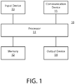
FIGURE 1 is a block diagram showing an apparatus according to at least one example embodiment; -
FIGURES 2A-2F are diagrams illustrating an apparatus according to at least one example embodiment -
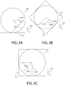
FIGURES 3A-3C are diagrams illustrating a display in relation to display angles according to at least one example embodiment; -
FIGURES 4A-4C are diagrams illustrating an array of array elements according to at least one example embodiment; -
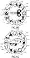
FIGURES 5A-5E are diagrams illustrating an array of menu items and/or an array of program identifiers according to at least one example embodiment; -
FIGURES 6A-6C are diagrams illustrating a virtual screen of information according to at least on example embodiment; -
FIGURE 7 is a flow diagram illustrating activities associated with determination of a contiguous subset of a sequential arrangement of information based, at least in part, on a display angle of a display according to at least one example embodiment; -
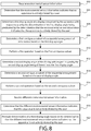
FIGURE 8 is a flow diagram illustrating activities associated with determination of a contiguous subset of a sequential arrangement of information based, at least in part, on a display angle of a display according to at least one example embodiment; -
FIGURE 9 is a flow diagram illustrating activities associated with determination of a contiguous subset of a sequential arrangement of information based, at least in part, on a display angle of a display according to at least one example embodiment; -
FIGURE 10 is a flow diagram illustrating activities associated with determination of a region of a virtual screen of information based, at least in part, on a display angle of a display according to at least one example embodiment; -
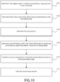
FIGURE 11 is a flow diagram illustrating activities associated with determination of an array element of an array of array elements based, at least in part, on a display angle of a display according to at least one example embodiment; -
FIGURE 12 is a flow diagram illustrating activities associated with determination of a menu item of an array of menu items based, at least in part, on a display angle of a display according to at least one example embodiment; and -
FIGURE 13 is a flow diagram illustrating activities associated with determination of a program identifier of an array of program identifiers based, at least in part, on a display angle of a display according to at least one example embodiment. - An embodiment of the invention and its potential advantages are understood by referring to
FIGURES 1 through 13 of the drawings. - Some embodiments will now be described more fully hereinafter with reference to the accompanying drawings, in which some, but not all, embodiments are shown. Various embodiments of the invention may be embodied in many different forms and should not be construed as limited to the embodiments set forth herein; rather, these embodiments are provided so that this disclosure will satisfy applicable legal requirements. Like reference numerals refer to like elements throughout. As used herein, the terms "data," "content," "information," and similar terms may be used interchangeably to refer to data capable of being transmitted, received and/or stored in accordance with embodiments of the present invention. Thus, use of any such terms should not be taken to limit the scope of embodiments of the present invention.
- Additionally, as used herein, the term 'circuitry' refers to (a) hardware-only circuit implementations (e.g., implementations in analog circuitry and/or digital circuitry); (b) combinations of circuits and computer program product(s) comprising software and/or firmware instructions stored on one or more computer readable memories that work together to cause an apparatus to perform one or more functions described herein; and (c) circuits, such as, for example, a microprocessor(s) or a portion of a microprocessor(s), that require software or firmware for operation even if the software or firmware is not physically present. This definition of 'circuitry' applies to all uses of this term herein, including in any claims. As a further example, as used herein, the term 'circuitry' also includes an implementation comprising one or more processors and/or portion(s) thereof and accompanying software and/or firmware. As another example, the term 'circuitry' as used herein also includes, for example, a baseband integrated circuit or applications processor integrated circuit for a mobile phone or a similar integrated circuit in a server, a cellular network apparatus, other network apparatus, and/or other computing apparatus.
- As defined herein, a "non-transitory computer-readable medium," which refers to a physical medium (e.g., volatile or non-volatile memory device), can be differentiated from a "transitory computer-readable medium," which refers to an electromagnetic signal.
-
FIGURE 1 is a block diagram showing an apparatus, such as anelectronic apparatus 10, according to at least one example embodiment. It should be understood, however, that an electronic apparatus as illustrated and hereinafter described is merely illustrative of an electronic apparatus that could benefit from embodiments of the invention and, therefore, should not be taken to limit the scope of the invention. Whileelectronic apparatus 10 is illustrated and will be hereinafter described for purposes of example, other types of electronic apparatuses may readily employ embodiments of the invention.Electronic apparatus 10 may be a personal digital assistant (PDAs), a pager, a mobile computer, a desktop computer, a television, a gaming apparatus, a laptop computer, a tablet computer, a media player, a camera, a video recorder, a mobile phone, a pendant apparatus, a monocular apparatus, a peripheral apparatus, a near eye display apparatus, a wearable apparatus, a viewfinder apparatus, a telescope apparatus, a monoscopic image apparatus, a binocular apparatus, a stereoscopic apparatus, a virtual reality apparatus, an augmented reality apparatus, a kaleidoscope apparatus, a global positioning system (GPS) apparatus, an automobile, a kiosk, an electronic table, and/or any other types of electronic systems. Moreover, the apparatus of at least one example embodiment need not be the entire electronic apparatus, but may be a component or group of components of the electronic apparatus in other example embodiments. For example, the apparatus may be an integrated circuit, a set of integrated circuits, and/or the like. - Furthermore, apparatuses may readily employ embodiments of the invention regardless of their intent to provide mobility. In this regard, even though embodiments of the invention may be described in conjunction with mobile applications, it should be understood that embodiments of the invention may be utilized in conjunction with a variety of other applications, both in the mobile communications industries and outside of the mobile communications industries.
- In at least one example embodiment,
electronic apparatus 10 comprisesprocessor 11 andmemory 12.Processor 11 may be any type of processor, controller, embedded controller, processor core, and/or the like. In at least one example embodiment,processor 11 utilizes computer program code to cause an apparatus to perform one or more actions.Memory 12 may comprise volatile memory, such as volatile Random Access Memory (RAM) including a cache area for the temporary storage of data and/or other memory, for example, non-volatile memory, which may be embedded and/or may be removable. The non-volatile memory may comprise an EEPROM, flash memory and/or the like.Memory 12 may store any of a number of pieces of information, and data. The information and data may be used by theelectronic apparatus 10 to implement one or more functions of theelectronic apparatus 10, such as the functions described herein. In at least one example embodiment,memory 12 includes computer program code such that the memory and the computer program code are configured to, working with the processor, cause the apparatus to perform one or more actions described herein. - The
electronic apparatus 10 may further comprise acommunication device 15. In at least one example embodiment,communication device 15 comprises an antenna, (or multiple antennae), a wired connector, and/or the like in operable communication with a transmitter and/or a receiver. In at least one example embodiment,processor 11 provides signals to a transmitter and/or receives signals from a receiver. The signals may comprise signaling information in accordance with a communications interface standard, user speech, received data, user generated data, and/or the like.Communication device 15 may operate with one or more air interface standards, communication protocols, modulation types, and access types. By way of illustration, theelectronic communication device 15 may operate in accordance with second-generation (2G) wireless communication protocols IS-136 (time division multiple access (TDMA)), Global System for Mobile communications (GSM), and IS-95 (code division multiple access (CDMA)), with third-generation (3G) wireless communication protocols, such as Universal Mobile Telecommunications System (UMTS), CDMA2000, wideband CDMA (WCDMA) and time division-synchronous CDMA (TD-SCDMA), and/or with fourth-generation (4G) wireless communication protocols, wireless networking protocols, such as 802.11, short-range wireless protocols, such as Bluetooth, and/or the like.Communication device 15 may operate in accordance with wireline protocols, such as Ethernet, digital subscriber line (DSL), asynchronous transfer mode (ATM), and/or the like. -
Processor 11 may comprise means, such as circuitry, for implementing audio, video, communication, navigation, logic functions, and/or the like, as well as for implementing embodiments of the invention including, for example, one or more of the functions described herein. For example,processor 11 may comprise means, such as a digital signal processor device, a microprocessor device, various analog to digital converters, digital to analog converters, processing circuitry and other support circuits, for performing various functions including, for example, one or more of the functions described herein. The apparatus may perform control and signal processing functions of theelectronic apparatus 10 among these devices according to their respective capabilities. Theprocessor 11 thus may comprise the functionality to encode and interleave message and data prior to modulation and transmission. Theprocessor 1 may additionally comprise an internal voice coder, and may comprise an internal data modem. Further, theprocessor 11 may comprise functionality to operate one or more software programs, which may be stored in memory and which may, among other things, cause theprocessor 11 to implement at least one embodiment including, for example, one or more of the functions described herein. For example, theprocessor 11 may operate a connectivity program, such as a conventional internet browser. The connectivity program may allow theelectronic apparatus 10 to transmit and receive internet content, such as location-based content and/or other web page content, according to a Transmission Control Protocol (TCP), Internet Protocol (IP), User Datagram Protocol (UDP), Internet Message Access Protocol (IMAP), Post Office Protocol (POP), Simple Mail Transfer Protocol (SMTP), Wireless Application Protocol (WAP), Hypertext Transfer Protocol (HTTP), and/or the like, for example. - The
electronic apparatus 10 may comprise a user interface for providing output and/or receiving input. Theelectronic apparatus 10 may comprise anoutput device 14.Output device 14 may comprise an audio output device, such as a ringer, an earphone, a speaker, and/or the like.Output device 14 may comprise a tactile output device, such as a vibration transducer, an electronically deformable surface, an electronically deformable structure, and/or the like.Output device 14 may comprise a visual output device, such as a display, a light, and/or the like. In at least one example embodiment, the apparatus causes display of information, the causation of display may comprise displaying the information on a display comprised by the apparatus, sending the information to a separate apparatus that comprises a display, and/or the like. The electronic apparatus may comprise aninput device 13.Input device 13 may comprise a light sensor, a proximity sensor, a microphone, a touch sensor, a force sensor, a button, a keypad, a motion sensor, a magnetic field sensor, a camera, and/or the like. A touch sensor and a display may be characterized as a touch display. In an embodiment comprising a touch display, the touch display may be configured to receive input from a single point of contact, multiple points of contact, and/or the like. In such an embodiment, the touch display and/or the processor may determine input based, at least in part, on position, motion, speed, contact area, and/or the like. In at least one example embodiment, the apparatus receives an indication of an input. The apparatus may receive the indication from a sensor, a driver, a separate apparatus, and/or the like. The information indicative of the input may comprise information that conveys information indicative of the input, indicative of an aspect of the input indicative of occurrence of the input, and/or the like. - The
electronic apparatus 10 may include any of a variety of touch displays including those that are configured to enable touch recognition by any of resistive, capacitive, infrared, strain gauge, surface wave, optical imaging, dispersive signal technology, acoustic pulse recognition or other techniques, and to then provide signals indicative of the location and other parameters associated with the touch. Additionally, the touch display may be configured to receive an indication of an input in the form of a touch event which may be defined as an actual physical contact between a selection object (e.g., a finger, stylus, pen, pencil, or other pointing device) and the touch display. Alternatively, a touch event may be defined as bringing the selection object in proximity to the touch display, hovering over a displayed object or approaching an object within a predefined distance, even though physical contact is not made with the touch display. As such, a touch input may comprise any input that is detected by a touch display including touch events that involve actual physical contact and touch events that do not involve physical contact but that are otherwise detected by the touch display, such as a result of the proximity of the selection object to the touch display. A touch display may be capable of receiving information associated with force applied to the touch screen in relation to the touch input. For example, the touch screen may differentiate between a heavy press touch input and a light press touch input. In at least one example embodiment, a display may display two-dimensional information, three-dimensional information and/or the like. - In embodiments including a keypad, the keypad may comprise numeric (for example, 0-9) keys, symbol keys (for example, #, *), alphabetic keys, and/or the like for operating the
electronic apparatus 10. For example, the keypad may comprise a conventional QWERTY keypad arrangement. The keypad may also comprise various soft keys with associated functions. In addition, or alternatively, theelectronic apparatus 10 may comprise an interface device such as a joystick or other user input interface. -
Input device 13 may comprise a media capturing element. The media capturing element may be any means for capturing an image, video, and/or audio for storage, display or transmission. For example, in at least one example embodiment in which the media capturing element is a camera module, the camera module may comprise a digital camera which may form a digital image file from a captured image. As such, the camera module may comprise hardware, such as a lens or other optical component(s), and/or software necessary for creating a digital image file from a captured image. Alternatively, the camera module may comprise only the hardware for viewing an image, while a memory device of theelectronic apparatus 10 stores instructions for execution by theprocessor 11 in the form of software for creating a digital image file from a captured image. In at least one example embodiment, the camera module may further comprise a processing element such as a co-processor that assists theprocessor 11 in processing image data and an encoder and/or decoder for compressing and/or decompressing image data. The encoder and/or decoder may encode and/or decode according to a standard format, for example, a Joint Photographic Experts Group (JPEG) standard format. -
FIGURES 2A-2F are diagrams illustrating an apparatus according to at least one example embodiment. The examples ofFIGURES 2A-2F are merely examples and do not limit the scope of the claims. For example, size of the apparatus, may vary, the shape of the apparatus may vary, the configuration of the apparatus may vary, and/or the like. - In some circumstances, it may be desirable to configure an electronic apparatus as a pendant apparatus. For example, configuration of an electronic apparatus as a pendant apparatus may permit a user of the electronic apparatus to easily transport the apparatus, wear the apparatus, interact with the apparatus, and/or the like. A pendant apparatus may refer to an electronic apparatus, such as an electronic apparatus similar as described regarding
FIGURE 1 , comprising a pendant form factor. For example, an apparatus comprising a pendant form factor may comprise provisions for attaching the pendant apparatus to a necklace, easily handling the apparatus in the hand of a user, standing the apparatus upright on a table, and/or the like. In at least one example embodiment, a pendant apparatus comprises a necklace. - In some circumstances, it may be desirable for a pendant apparatus to comprise a display. For example, it may be desirable to display information to a user of the pendant apparatus. It may be desirable, in some circumstances, for a display comprised by a pendant apparatus to be a near eye display. For example, a near eye display may allow for the size of the apparatus to remain compact, allow for a user to view the display at a near distance with clarity, and/or the like. In at least one example embodiment, a pendant apparatus comprises a near eye display. In some circumstances, the pendant apparatus may be configured such that the near eye display is best viewed by a single eye of the user. In circumstances such as these, the pendant apparatus may be referred to as a monocular apparatus.
- In some circumstances it may be desirable for a pendant apparatus to comprise multiple displays. For example, a pendant apparatus may be configured as a binocular apparatus. A binocular apparatus may refer to an electronic apparatus in which a first display is configured for viewing by a left eye of a user and a second display is configured for viewing by a right eye of a user, such that the displays may be viewed simultaneously by the user.
- In some circumstances, it may be desirable for a pendant apparatus to receive environmental sensor information. For example, the apparatus may determine an apparatus orientation, a user input, an apparatus mode, and/or the like by receiving environmental sensor information from at least one environmental sensor. An environmental sensor may refer to an input device similar as described regarding
FIGURE 1 . For example, an environmental sensor may be a touch sensor, an orientation sensor, an accelerometer, an infrared sensor, an optical sensor, a proximity sensor, a gyro, a magnetometer, an inertial sensor, and/or the like. - The examples of
FIGURE 2A-2C arediagrams illustrating apparatus 200 according to at least one example embodiment.FIGURE 2A is a perspective view,FIGURE 2B is a front view, andFIGURE 2C is a cutaway view of the same example. In the example ofFIGURES 2A-2C ,apparatus 200 comprisesenclosure 202,display 204,environmental sensors processor 230. The example ofFIGURES 2A-2C depictapparatus 200 as a pendant apparatus, but it should be understood thatapparatus 200 may be any type of electronic apparatus. - In some circumstances, a user may have an electronic apparatus similar as described regarding
FIGURES 2A-2C under his control. In circumstances such as these, the apparatus may receive a notification of a message, a calendar alert, and/or the like. It may be desirable in circumstances such as these for the viewer to actively view the apparatus to perceive the notification, dismiss the alert, and/or the like. For example, the user may place the apparatus near his eyes, face the apparatus in his direction, and/or the like to actively view the apparatus. During active viewing of the apparatus, a user may be focusing his attention on the apparatus, interacting with the apparatus, and/or the like. For example, during an active viewing of the apparatus, a user may be actively reading information displayed on a display comprised by the apparatus. -
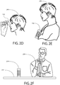
FIGURE 2D is adiagram illustrating user 240 actively viewing a display comprised byapparatus 242. Even though the example ofFIGURE 2D depictsapparatus 242 as a pendant apparatus,apparatus 242 may be any type of electronic apparatus. - As previously described, in some circumstances, a user may have an electronic apparatus similar as described regarding
FIGURES 2A-2C under his control. In some circumstances, an apparatus may be positioned such that the apparatus may not be actively viewed by the user. For example, the apparatus may be placed on a desk, placed in the user's pocket, worn on the user's body, and/or the like. In circumstances such as these, a display comprised by an apparatus may be passively viewed by a user of the apparatus. During passive viewing of the apparatus, a user may be focusing his attention on something other than the apparatus, ignoring the apparatus, viewing the apparatus with his peripheral vision, viewing the apparatus from a distance, and/or the like. For example, during passive viewing of the apparatus, a user may be reading information displayed on a display comprised by a different apparatus, performing a task independent of the apparatus, and/or the like. In this manner, an apparatus that is being passively viewed is not being actively viewed. -
FIGURE 2E is adiagram illustrating user 244 passively viewing a display comprised byapparatus 246. Even though the example ofFIGURE 2E depictsapparatus 244 as a pendant apparatus,apparatus 244 may be any type of electronic apparatus. It can be seen thatapparatus 246 is attached to a necklace worn byuser 244. Even though the example ofFIGURE 2E depictsapparatus 246 as being worn byuser 244,apparatus 246 may be attached touser 244's clothing, carried in a pocket, carried inuser 244's hand, and/or the like, such thatapparatus 246 may be passively viewed byuser 244. -
FIGURE 2F is adiagram illustrating user 250 sitting atdesk 252 passively viewing a display comprised byapparatus 254. Even though the example ofFIGURE 2F depictsapparatus 254 as a pendant apparatus,apparatus 254 may be any type of electronic apparatus. It can be seen thatapparatus 254 is positioned upright on the top surface ofdesk 252. Even though the example ofFIGURE 2E depicts apparatus as upright on the top surface ofdesk 252,apparatus 254 may positioned in other positions such thatapparatus 254 may be passively viewed byuser 250. For example,apparatus 254 may be placed upright on a floor surface, laying on a side ofapparatus 254 on top of a surface ofdesk 252, and/or the like. - As previously described, a user may be actively viewing an apparatus. For example, the user may be interacting with the apparatus in a manner similar to
user 240 ofFIGURE 2D interacting withapparatus 242. In circumstances such as these, it may be desirable for an apparatus to enter an active viewing state of the apparatus. For example, an apparatus may determine that the apparatus is being actively viewed by a user based, at least in part, on the active viewing state of the apparatus. An active viewing state may be characterized by a state in which the apparatus is configured in a manner that avoids visual impairment compensation. Visual impairment compensation may refer to the rendering of visual information in a manner that it is easier to perceive and/or comprehend when viewing conditions are less than ideal. For example, visual information rendered with visual impairment compensation may be rendered with a lower pixel resolution, with a higher brightness level, without textual information, and/or the like. Alternatively, visual information rendered without visual impairment compensation may be rendered with an increased pixel resolution, with a lower brightness level, with textual information, and/or the like. - As previously described, a user may be passively viewing an apparatus, not viewing an apparatus, and/or the like. For example, the apparatus may be passively viewed similar as described regarding
FIGURES 2E-2F . In circumstances such as these, the user may transition from passive to active viewing. For example, a user may move the apparatus from a position similar as depicted inFIGURES 2E or 2F to a position similar as depicted inFIGURE 2D . In circumstances such as these, it may be desirable for an apparatus to enter an active viewing state of the apparatus, based, at least in part, on environmental sensor information. For instance, environmental sensor information may indicate that the apparatus is actively viewed by a user. For example, environmental sensor information may indicate that the apparatus has an apparatus orientation with respect to a user. In such an example, the apparatus orientation may be similar to the orientation ofapparatus 242 ofFIGURE 2D with respect touser 240. In at least one example embodiment, the apparatus enters an active viewing state of the apparatus based, at least in part, on the determination that the environmental sensor information indicates that the apparatus is actively viewed by the user. - In some circumstances, an orientation of the apparatus may indicate that the apparatus is actively viewed by the user. For example, the apparatus may be oriented such that a display comprised by the apparatus is in a position in which the view is unobscured. For instance, the orientation of the apparatus when being actively viewed may be similar to the orientation of
apparatus 242 ofFIGURE 2D . In circumstances such as these, it may be desirable for environmental sensor information to indicate that the apparatus is actively viewed by the user based, at least in part, on the orientation of the apparatus. In at least one example embodiment, determination that the environmental sensor information indicates that the apparatus is actively viewed by a user comprises determination that an orientation of the apparatus indicates that the apparatus is actively viewed by the user. In some circumstances, the direction of gravity in relation to an apparatus may indicate may indicate that apparatus is actively viewed by a user. For example, the apparatus may be actively viewed if the direction of gravity substantially parallel to a surface of a display comprised by the apparatus. For instance, it can be seen that the direction of gravity inFIGURE 2D is substantially parallel to the display ofapparatus 242. In at least one example embodiment, environmental sensor information comprises information indicative of a direction of gravity in relation to the apparatus. In at least one example embodiment, the direction of gravity is substantially parallel to the surface of the display in circumstances where the direction of gravity deviates from being exactly parallel to the surface of the display within a predetermined threshold angle. In at least one example embodiment, the threshold angle is a predetermined angle, such as 15 degrees, 28 degrees, 45 degrees, and/or the like. In at least one example embodiment, the threshold angle varies based, at least in part, on one or more physical characteristics of the apparatus, such as the size of the apparatus, resolution of the display, obscurance of the display by a housing of the apparatus, and/or the like. In at least one example embodiment, the threshold angle may be based, at least in part, on other environmental circumstances, such as the distance between the apparatus and the user, contact between the user and the apparatus, and/or the like. For example, the threshold angle may be larger when the user is further from the apparatus, when the apparatus is larger in size, and/or the like. In another example, the threshold angle may be smaller when the user is closer to the apparatus, when the apparatus is smaller in size, and/or the like. - In some circumstances, an eye of a user proximate to a display comprised by an apparatus may indicate that the apparatus is actively viewed by the user. For example, the display may be a near eye display. A user actively viewing a near eye display may have their eye proximate to the display in a similar manner to
user 240's eye being proximate toapparatus 242 ofFIGURE 2D . In circumstances such as these, it may be desirable for environmental sensor information to indicate that the apparatus is actively viewed by the user based, at least in part, a determination that an eye of the user is proximate to the display. For example, the environmental sensor may be a proximity sensor, an infrared sensor, a sonar, a radar, a capacitive sensor, a light sensor, and/or the like, comprised by the apparatus. In at least one example embodiment, determination that the environmental sensor information indicates that the apparatus is actively viewed by a user comprises determination that an eye of the user is proximate to the display. In at least one example embodiment, the environmental sensor information comprises proximity sensor information that indicates proximity of the user in relation to the display. In at least one example embodiment, the proximity sensor information indicates proximity of the user in circumstances where the proximity sensor information indicates an object being within a threshold distance from the display. In at least one example embodiment, the threshold distance is a predetermined distance, such as 2 centimeters, 4 centimeters, 8 centimeters, and/or the like. In at least one example embodiment, the threshold distance varies based, at least in part, on one or more physical characteristics of the apparatus, such as the size of the apparatus, resolution of the display, obscurance of the display by a housing of the apparatus, and/or the like. In at least one example embodiment, the threshold distance may be based, at least in part, on other environmental circumstances, such as the distance between the apparatus and the user, contact between the user and the apparatus, and/or the like. For example, the threshold distance may be larger when the user is further from the apparatus, when the apparatus is larger in size, and/or the like. In another example, the threshold distance may be smaller when the user is closer to the apparatus, when the apparatus is smaller in size, and/or the like. - In some circumstances, a user holding an apparatus may indicate that the apparatus is actively viewed by the user. For example, a user may necessarily hold an apparatus while interacting with software associated with the apparatus. For instance, the apparatus may comprise touch sensors as an input for software control. A user actively viewing an apparatus may hold the apparatus in a similar manner to
user 240holding apparatus 242 ofFIGURE 2D . In circumstances such as these, it may be desirable for environmental sensor information to indicate that the apparatus is actively viewed by the user based, at least in part, on determination that the user is holding the apparatus. In at least one example embodiment, determination that the environmental sensor information indicates that the apparatus is actively viewed by a user comprises determination that the user is holding the apparatus. In at least one example embodiment, the environmental sensor information comprises touch sensor information indicative of a user holding the apparatus. - In some circumstances, it may be desirable to determine that an apparatus is actively viewed by a user based, at least in part, on a combination of environmental sensor information received from different environmental sensors. For instance, environmental sensor information may indicate that the apparatus is being actively viewed when no active viewing is occurring. For example, a user may briefly hold an apparatus to move it out of his way, or the apparatus may have an orientation consistent with viewing of the apparatus even though the apparatus is not being actively viewed. In circumstances such as these, the apparatus may determine that an apparatus is actively viewed by a user if a combination of environmental sensor information received from different environmental sensors is consistent with being actively viewed by a user. For example, the apparatus may determine that it is being actively viewed if it has a particular orientation and is simultaneously being held, if the apparatus is being held and the apparatus is proximate to the eye of the user, and/or the like.
- As previously described, a user may be passively viewing an apparatus, not viewing an apparatus, and/or the like. For example, the apparatus may be passively viewed similar as described regarding
FIGURES 2E-2F . In circumstances such as these, it may be desirable for an apparatus to enter a passive viewing state of the apparatus. For example, an apparatus may determine that the apparatus is not being actively viewed by a user based, at least in part, on the passive viewing state of the apparatus. A passive viewing state may be an operational state in which information is caused to be displayed in conformance with an impaired-viewing display mode absent display of information in an unimpaired-viewing display mode. A passive viewing state may be characterized by a state in which the apparatus is configured in a manner that provides visual impairment compensation. - As previously described, a user may be actively viewing an apparatus. For example, the user may be interacting with the apparatus in a manner similar to
user 240 ofFIGURE 2D interacting withapparatus 242. In circumstances such as these, the user may transition from active to passive viewing. For example, a user may move the apparatus from a position similar as depicted inFIGURE 2D to a position similar as depicted inFIGURES 2E and/orFIGURE 2F . In circumstances such as these, it may be desirable for an apparatus to enter a passive viewing state of the apparatus, based, at least in part, on environmental sensor information. For instance, environmental sensor information may indicate that the apparatus is not actively viewed by a user. For example, environmental sensor information may indicate that the apparatus has an apparatus orientation with respect to a user similar to the orientation ofapparatus 246 ofFIGURE 2E with respect touser 244, similar to the orientation ofapparatus 254 ofFIGURE 2F with respect touser 250, and/or the like. In at least one example embodiment, the apparatus enters a passive viewing state of the apparatus based, at least in part, on the determination that the environmental sensor information indicates that the apparatus is not actively viewed by the user. - In some circumstances, an orientation of the apparatus may indicate that the apparatus is not actively viewed by the user. For example, the apparatus may be oriented such that a display comprised by the apparatus is in a position in which the view is obscured. For instance, the orientation of the apparatus when being actively viewed may be similar to the orientation of
apparatus 246 ofFIGURE 2E . In circumstances such as these, it may be desirable for environmental sensor information to indicate that the apparatus is not actively viewed by the user based, at least in part, on the orientation of the apparatus. In at least one example embodiment, determination that the environmental sensor information indicates that the apparatus is not actively viewed by a user comprises determination that an orientation of the apparatus indicates that the apparatus is not actively viewed by the user. In at least one example embodiment, the environmental sensor is a magnetometer, and environmental sensor information is indicative of an orientation of the apparatus relative to the magnetic north pole of the Earth. In some circumstances, the direction of gravity in relation to an apparatus may indicate may indicate that apparatus is not actively viewed by a user. For example, the apparatus may not be actively viewed if the direction of gravity substantially perpendicular to a surface of a display comprised by the apparatus. For instance, it can be seen that the direction of gravity inFIGURE 2E is substantially perpendicular to the display ofapparatus 246, and that the direction of gravity inFIGURE 2F is substantially perpendicular to the display ofapparatus 254. In at least one example embodiment, the direction of gravity is substantially perpendicular to the surface of the display in circumstances where the direction of gravity deviates from being exactly perpendicular to the surface of the display within a predetermined threshold angle. In at least one example embodiment, the threshold angle may be a predetermined angle, such as 15 degrees, 20 degrees, 45 degrees, and/or the like. In at least one example embodiment, the threshold angle varies based, at least in part, on one or more physical characteristics of the apparatus, such as the size of the apparatus, resolution of the display, obscurance of the display by a housing of the apparatus, and/or the like. In at least one example embodiment, the threshold angle may be based, at least in part, on other environmental circumstances, such as the distance between the apparatus and the user, contact between the user and the apparatus, and/or the like. For example, the threshold angle may be larger when the user is further from the apparatus, when the apparatus is larger in size, and/or the like. In another example, the threshold angle may be smaller when the user is closer to the apparatus, when the apparatus is smaller in size, and/or the like. - In some circumstances, absences of an eye of a user proximate to a display comprised by an apparatus may indicate that the apparatus is not actively viewed by the user. For example, the display may be a near eye display. A user not actively viewing a near eye display may have their eye distant to the display in a similar manner to
user 244's eye being distant toapparatus 246 ofFIGURE 2E ,user 250's eye being distant toapparatus 254 ofFIGURE 2F , and/or the like. In circumstances such as these, it may be desirable for environmental sensor information to indicate that the apparatus is not actively viewed by the user based, at least in part, a determination that an eye of the user is distant to the display. For example, the environmental sensor may be a proximity sensor, an infrared sensor, a sonar, a radar, a capacitive sensor, a light sensor, and/or the like comprised by the apparatus. In at least one example embodiment, determination that the environmental sensor information indicates that the apparatus is not actively viewed by a user comprises determination that an eye of the user is distant to the display. In at least one example embodiment, the proximity sensor information indicates distance from the user in circumstances where the proximity sensor information indicates an object being beyond a threshold distance from the display. In at least one example embodiment, the threshold distance is a predetermined distance, such as 20 centimeters, 30 centimeters, 50 centimeters, and/or the like. In at least one example embodiment, the threshold distance varies based, at least in part, on one or more physical characteristics of the apparatus, such as the size of the apparatus, resolution of the display, obscurance of the display by a housing of the apparatus, and/or the like. In at least one example embodiment, the threshold distance may be based, at least in part, on other environmental circumstances, such as the distance between the apparatus and the user, contact between the user and the apparatus, and/or the like. For example, the threshold distance may be larger when the user is further from the apparatus, when the apparatus is larger in size, and/or the like. In another example, the threshold distance may be smaller when the user is closer to the apparatus, when the apparatus is smaller in size, and/or the like. - In some circumstances, absence of a user holding an apparatus may indicate that the apparatus is not actively viewed by the user. For example, it may be necessary for a user to hold an apparatus to interact with software associated with the apparatus. For instance, the apparatus may comprise touch sensors as an input for software control. A user that is not actively viewing an apparatus may not be holding the apparatus in a similar manner to
user 244 not holdingapparatus 246 ofFIGURE 2E ,user 250 not holdingapparatus 254 ofFIGURE 2F , and/or the like. In circumstances such as these, it may be desirable for environmental sensor information to indicate that the apparatus is not actively viewed by the user based, at least in part, on determination that the user is not holding the apparatus. In at least one example embodiment, determination that the environmental sensor information indicates that the apparatus is not actively viewed by a user comprises determination that the user is not holding the apparatus. In at least one example embodiment, the environmental sensor information comprises touch sensor information indicative of a user not holding the apparatus. - In some circumstances, it may be desirable to determine that an apparatus is not actively viewed by a user based, at least in part, on a combination of environmental sensor information received from different environmental sensors. For instance, environmental sensor information may indicate that the apparatus is not being actively viewed when active viewing is occurring. For example, a user may briefly pull the apparatus away from his eye, the apparatus may have an orientation inconsistent with viewing of the apparatus even though the apparatus is being actively viewed, and/or the like. In circumstances such as these, the apparatus may determine that an apparatus is not actively viewed by a user if a combination of environmental sensor information received from different environmental sensors is consistent with not being actively viewed by a user. For example, the apparatus may determine that it is not being actively viewed if it has a particular orientation and is simultaneously not being held, if the apparatus is not being held and the apparatus is distant from the eye of the user, and/or the like.
-
FIGURES 3A-3C are diagrams illustrating a display in relation to display angles according to at least one example embodiment. The examples ofFIGURES 3A-3C are merely examples and do not limit the scope of the claims. For example, display design and/or shape may vary, display configuration may vary, display angle may vary, and/or the like. - As previously discussed, in some circumstances, a user may desire to utilize an apparatus, such as the apparatus described in the examples of
FIGURES 2A-2F , to perceive and/or interact with information, such as content, software, textual information, graphical information, and/or the like. For example, while the apparatus is being actively viewed by the user, the user may view textual content, browse with graphical content, interact with software, and/or the like. As such, it may be desirable to provide for a method of interacting with such information via the apparatus that is easy and intuitive. The examples ofFIGURES 2A-2F depict an apparatus that is characterized by a tubular form factor, similar to a monocular apparatus, a kaleidoscope, and/or the like. As the user peers into the apparatus at a display comprised by the apparatus, it may be desirable to provide for an easy and intuitive manner in which to interact with information displayed on the display. In many circumstances, a user may be familiar with one or more manners in which to scroll, pan, browse, navigate, and/or the like, within such information. For example, the user may be familiar with a rotational input, a turning input, and/or the like. As such, it may be desirable to configure the apparatus such that the user of the apparatus may interact with information displayed on the display by way of a rotational input, a turning input, and/or the like. For example, the user may tumble the apparatus about its axis while peering at the display comprised by the apparatus. In this manner, the apparatus itself may be utilized as an input device for purposes associated with viewing textual content, browsing graphical content, interacting with software, and/or the like. - In order to facilitate such interaction with information by way of an apparatus, it may be desirable to determine an orientation of the apparatus. In many circumstances, a user may be interacting with information while the user is peering at a display of the apparatus. In such circumstances, it may be desirable to configure the apparatus such that information displayed on the display remains in an upright orientation while the user of the apparatus rolls, spins, twists, and/or the like, the apparatus. As such, it may be desirable to determine an orientation of the apparatus based upon the rotation of the display of the apparatus with respect to a gravitational force. In at least one example embodiment, an apparatus determines a display angle of a display comprised by the apparatus. In such an example embodiment, the display angle may be an angle of the display with respect to gravity. For example, determination of the display angle with respect to gravity may comprise receipt of sensor information that indicates a direction of gravity, and determination of the display angle may be based, at least in part, on the direction of gravity in relation to the display. In such an example, the determination of the display angle may comprise determination that the direction of gravity differs from a predetermined reference angle by the display angle. The predetermined reference angle may, for example, correspond with a predetermined edge of the display, a predetermined position on the display, a predetermined orientation of the display, and/or the like. In at least one example embodiment, the predetermined reference angle corresponds with an angle that is perpendicular to a bottom of the display. In such an example embodiment, the bottom of the display may be a lower edge of the display, a position at the intended bottom of the display, a bottom of the display such that the display is in an upright orientation while the apparatus is in an upright position, and/or the like. The sensor information may be received from an accelerometer sensor, a gyroscopic sensor, an orientation sensor, a gravitational force sensor, and/or the like.
-
FIGURES 3A-3C are diagrams illustrating a display in relation to display angles according to at least one example embodiment. The example ofFIGURE 3A depictsdisplay 300, havingbottom edge 301, in relation togravity 302 and display angles 304A, 304B, and 304C. The example ofFIGURE 3B depictsdisplay 310, havingbottom edge 311, in relation togravity 312 and display angles 314A, 314B, and 314C. The example ofFIGURE 3C depictsdisplay 320, havingbottom edge 321, in relation togravity 322 and display angles 324A, 324B, and 324C. In some circumstances,display 300 ofFIGURE 3A may correspond withdisplay 310 ofFIGURE 3B and/or display 320 ofFIGURE 3C . In such circumstances, each of display angles 304A-304C ofFIGURE 3A may correspond with each of display angles 314A-314C ofFIGURE 3B and/or each of display angles 324A-324C ofFIGURE 3C , respectively. In this manner, the progression of the example ofFIGURES 3A-3C may depict a display that is being reoriented from the display angle ofdisplay 300 in the example ofFIGURE 3A , to the display angle ofdisplay 310 in the example ofFIGURE 3B , and to the display angle ofdisplay 320 in the example ofFIGURE 3C . - In the example of
FIGURE 3A ,display angle 304A is approximately parallel togravity 302. As can be seen, display 300 is oriented such thatbottom edge 301 is positioned at the bottom ofdisplay 300, andgravity 302 is perpendicular tobottom edge 301 ofdisplay 300. In this manner,display 300 may be oriented in an upright orientation, a predetermined default orientation, and/or the like. As can be seen,display angle 304A is directed towards and is perpendicular tobottom edge 301. In this manner,display angle 304A may indicate that the display is in an upright orientation, a predetermined default orientation, and/or the like. For example,display angle 304A may indicate that the display is rotated 0-degrees from the upright orientation of the display, from the predetermined default orientation of the display, and/or the like. In this manner, the display angle ofdisplay 300 may be 0-degrees. - In the example of
FIGURE 3B ,display angle 314B is approximately parallel togravity 312. As can be seen, display 310 is oriented such thatbottom edge 311 has rotated in relation tobottom edge 301 ofFIGURE 3A , andgravity 312 fails to be perpendicular tobottom edge 311 ofdisplay 310. In this manner,display 310 may fail to be oriented in an upright orientation, a predetermined default orientation, and/or the like. As can be seen,display angle 314A is directed towards and is perpendicular tobottom edge 301, anddisplay angle 314B is approximately parallel togravity 312. In this manner,display angle 314B may indicate an angle of rotation away fromdisplay angle 314A. For example,display angle 314B may indicate that the display is rotated 45-degrees from the upright orientation of the display, from the predetermined default orientation of the display, and/or the like. In this manner, the display angle ofdisplay 310 may be 45-degrees. - In the example of
FIGURE 3C ,display angle 324C is approximately parallel togravity 322. As can be seen, display 320 is oriented such thatbottom edge 321 has rotated in relation tobottom edge 301 ofFIGURE 3A andbottom edge 311 ofFIGURE 3B , andgravity 322 fails to be perpendicular tobottom edge 321 ofdisplay 320. In this manner,display 320 may fail to be oriented in an upright orientation, a predetermined default orientation, and/or the like. As can be seen,display angle 324A is directed towards and is perpendicular tobottom edge 321, anddisplay angle 324C is approximately parallel togravity 322. In this manner,display angle 324C may indicate an angle of rotation away fromdisplay angle 324A. For example,display angle 324C may indicate that the display is rotated 90-degrees from the upright orientation of the display, from the predetermined default orientation of the display, and/or the like. In this manner, the display angle ofdisplay 320 may be 90-degrees. - As discussed previously, in many circumstances, a user may desire to interact with information displayed on a display of an apparatus by way of reorienting the apparatus from a first orientation to a second orientation, from a first orientation to a third orientation, and/or the like. In order to facilitate such interaction, it may be desirable to configure an apparatus such that the apparatus may enable such interaction by way of reorientation of the apparatus, reorientation of the display, and/or the like. As such, it may be desirable to configure the apparatus such that the apparatus may determine a display angle of the first orientation, a display angle of the second orientation, and/or a display angle of the third orientation, such that the apparatus may facilitate interaction with information by way of reorienting the apparatus from a display angle to a different display angle. In at least one example embodiment, an apparatus determines a contiguous subset of a sequential arrangement of information based, at least in part, on a display angle. In such an example embodiment, the sequential arrangement of information may be any information that is arranged in a sequential or ordered manner. For example, the sequential arrangement of information may be a list of information, an array of information, a matrix of information, a group of textual messages, a textual document, a gallery of graphical content, a collection of still frames of a video, and/or the like. In such an example, the contiguous subset of the sequential arrangement of information may be, respectively, one or more items on the list of information, one or more array elements of the array of information, one or more matrix elements of the matrix of information, one or more textual messages of the group of textual messages, one or more words of the textual document, one or more pictures of the gallery of pictures, one or more still frames of the video, and/or the like.
- As discussed previously, in order to interact with information displayed on the display of an apparatus, the user of the apparatus may reorient the apparatus and/or the display such that the display angle of the display changes from a display angle to a different display angle. As discussed previously, in at least one example embodiment, an apparatus determines a display angle of the display with respect to gravity, and determines a contiguous subset of a sequential arrangement of information based, at least in part, on the display angle. In such an example embodiment, the user may subsequent reorient the apparatus and/or the display such that the display is at a different display angle. In at least one example embodiment, an apparatus determines another display angle of the display with respect to gravity. In such an example embodiment, the other display angle may be different from the display angle. In such an example embodiment, the apparatus may determine another contiguous subset of the sequential arrangement based, at least in part, on the other display angle. The contiguous subset may be different from the other contiguous subset, the contiguous subset may comprise a portion of the other contiguous subset that is less than an entirety of the other contiguous subset, and/or the like.
- In order to provide for easy and intuitive interaction by way of reorienting a display of an apparatus from a display angle to a different display angle, it may be desirable to configure the apparatus such that the determination of a contiguous subset of a sequential arrangement of information is performed in a manner that is intuitive and predictable. As such, it may be desirable to base such a determination, at least in part, on a difference between the display angle and the other display angle. As discussed previously, an apparatus may determine a first display angle of the display with respect to gravity, determine a first contiguous subset of a sequential arrangement of information, and, subsequently, determine a second display angle of the display with respect to gravity. As such, it may be desirable to determine a second contiguous subset of a sequential arrangement of information based, at least in part, on the difference between the first display angle and the second display angle. In at least one example embodiment, determination of a second contiguous subset comprises determination of an angular change between a first display angle and a second display angle, and determination of the second contiguous subset based, at least in part, on the angular change and the first contiguous subset. For example, the angular change may be such that the second contiguous subset comprises at least a portion of the first contiguous subset, such that the second contiguous subset fails to comprise any portion of the first contiguous subset, and/or the like. As such, in such an example, it may be desirable to determine the second contiguous subset based, at least in part, on a relative position of the first contiguous subset and/or the second contiguous subset within the sequential arrangement of information. For example, the first contiguous subset may correspond with a first position within the sequential arrangement of information. In such an example, the determination of a second contiguous subset based, at least in part, on the angular change and the first contiguous subset may comprise determination of a magnitude of the angular change, and determination of a second position within the sequential arrangement of information based, at least in part, on the first position and the magnitude of the angular change. In this manner, the apparatus may determine the second contiguous subset such that the second contiguous subset corresponds with the second position within the sequential arrangement of information. The difference between the first position and the second position may be proportional to the magnitude of the angular change, scaled based, at least in part, on the magnitude of the angular change, dependent upon the magnitude of the angular change, and/or the like.
- For example, an angular change between the display angle of
display 300 ofFIGURE 3A and the display angle ofdisplay 310 ofFIGURE 3B may be 45-degrees. In such an example, the display angle ofdisplay 300 ofFIGURE 3A may be 0-degrees and the display angle ofdisplay 310 ofFIGURE 3B may be 45-degrees. As such, the difference between the two display angles, and thus the angular change, may be 45-degrees. In another example, an angular change between the display angle ofdisplay 310 ofFIGURE 3B and the display angle ofdisplay 320 ofFIGURE 3C may be 45-degrees. In such an example, the display angle ofdisplay 310 ofFIGURE 3B may be 45-degrees and the display angle ofdisplay 320 ofFIGURE 3C may be 90-degrees. As such, the difference between the two display angles, and thus the angular change, may be 45-degrees. In yet another example, an angular change between the display angle ofdisplay 300 ofFIGURE 3A and the display angle ofdisplay 320 ofFIGURE 3C may be 90-degrees. In such an example, the display angle ofdisplay 300 ofFIGURE 3A may be 0-degrees and the display angle ofdisplay 320 ofFIGURE 3C may be 90-degrees. As such, the difference between the two display angles, and thus the angular change, may be 90-degrees. - In many circumstances, a user may desire to interact with information displayed on a display of an apparatus in different manners. For example, the user may desire to scroll forward through information, browse backwards through content, navigate leftward through a menu, increment a value, decrease a size of an image, and/or the like. As such, it may be desirable to determine a direction in which a display has been reoriented. For example, the apparatus and/or the display may be rolled in one direction, the apparatus and/or the display may be rotated in a different direction, and/or the like. As such, it may be desirable to configure an apparatus such that the apparatus may determine a direction associated with an angular change of a display. In at least one example embodiment, an apparatus determines a direction of an angular change, and determines a second position within a sequential arrangement of information based, at least in part, on a first position, a magnitude of an angular change, and a direction of the angular change. In such an example embodiment, a positional direction from the first position to the second position may correspond with the direction of the angular change. For example, an incremental positional direction may correspond with a clockwise direction of the angular change and a decremental positional direction may correspond with a counter-clockwise direction of the angular change. In another example, an incremental positional direction may correspond with a counter-clockwise direction of the angular change and a decremental positional direction may correspond with a clockwise direction of the angular change.
- For example, an angular change between the display angle of
display 300 ofFIGURE 3A and the display angle ofdisplay 310 ofFIGURE 3B may be positive 45-degrees. In such an example, the display angle ofdisplay 300 ofFIGURE 3A may be 0-degrees and the display angle ofdisplay 310 ofFIGURE 3B may be 45-degrees. In such an example, a rotation in a clockwise direction may be indicative of an incremental rotation, a positive direction, and/or the like. As such, the difference between the two display angles, and thus magnitude and/or the direction of the angular change, may be positive 45-degrees, clockwise 45-degrees, and/or the like. In another example, an angular change between the display angle ofdisplay 320 ofFIGURE 3C and the display angle ofdisplay 300 ofFIGURE 3A may be negative 90-degrees. In such an example, the display angle ofdisplay 320 ofFIGURE 3C may be 90-degrees and the display angle ofdisplay 300 ofFIGURE 3A may be 0-degrees. In such an example, a rotation in a counter-clockwise direction may be indicative of a decremental rotation, a negative direction, and/or the like. As such, the difference between the two display angles, and thus magnitude and/or the direction of the angular change, may be negative 90-degrees, counter-clockwise 90-degrees, and/or the like. -
FIGURES 4A-4C are diagrams illustrating an array of array elements according to at least one example embodiment. The examples ofFIGURES 4A-4C are merely examples and do not limit the scope of the claims. For example, display configuration may vary, display angle may vary, array of array elements configuration and/or arrangement may vary, array element configuration may vary, representations of array elements may vary, representation of an array of array elements may vary, representation of selection of an array element may vary, and/or the like. - As previously discussed, in some circumstances, a user may desire to utilize an apparatus to perceive and/or interact with information, such as content, software, textual information, graphical information, and/or the like. In such circumstances, the apparatus may determine a display angle of a display of the apparatus, and determine a contiguous subset of a sequential arrangement of information based, at least in part, on the display angle. In order to facilitate user viewing of the contiguous subset of a sequential arrangement of information, user perception of information associated with the contiguous subset of a sequential arrangement of information, user interaction with the contiguous subset of a sequential arrangement of information, and/or the like, it may be desirable to perform one or more operations based, at least in part, on the contiguous subset. For example, the apparatus may determine a first display angle of a display comprised by the apparatus and a first contiguous subset of a sequential arrangement of information, and, subsequently, perform a first operation based, at least in part, on the first contiguous subset. In such an example, the apparatus may be reoriented by a user such that the apparatus determines a second display angle of the display, and determines a second contiguous subset of the sequential arrangement of information. In such an example, the apparatus may perform a second operation based, at least in part, on the second contiguous subset. In such an example embodiment, the first operation may be different from the second operation, the first operation may be similar to the second operation, the first operation may be identical the second operation, and/or the like.
- In many circumstances, a user may desire to interact with information in various ways depending on what type of information the user is interacting with. For example, the user may desire to pan across an image such that various portions of the image are displayed, browse through an image gallery such that images are successively displayed, select a menu item, launch an application, display a textual document such that the user may read through the entirety of the textual document a portion at a time, and/or the like. As such, it may be desirable to configure an apparatus such that the apparatus performs various operations based, at least in part, on a type or classification of a sequential arrangement of information being interacted with.
- In at least one example embodiment, the sequential arrangement of information is an array of array elements. For example, an array element may be an image, an icon, a value, a word, and/or the like. In such an example, the array of array elements may be an image gallery comprising the image, a menu comprising the icon, a list of numbers comprising the value, a sentence comprising the word, and/or the like. In such an example, a contiguous subsection of the sequential arrangement of information may be an array element. For example, a first contiguous subset may be a first array element of the array, and a second contiguous subset may be a second array element of the array. In this manner, a contiguous subset may comprise a single array element, a plurality of array elements, and/or the like.
- In the context of an array of array elements, a user may desire to indicate selection of a particular array element of the array of array elements. For example, a first operation may comprise selection of the first array element, and a second operation may comprise selection of the second array element. In at least one example embodiment, an operation comprises display of an indication of the selection of the first array element. In such an example embodiment, it may be desirable to orient display of the indication of the selection of the first array element such that the indication is perceived as upright when viewed by a user of the apparatus. For example, a user may roll the apparatus and/or the display such that the display is at a first display angle. In such an example, it may be desirable to display the indication such that the indication is upright relative to gravity, is upright relative to a current orientation of the display, and/or the like. As such, in at least one example embodiment, an operation comprises display of an indication of the selection of an array element on a display such that the orientation of the indication of the selection of the array element on the display corresponds with a display angle of the display. For example, a first operation may comprise display of an indication of a selection of a first array element on a display such that the orientation of the indication of the selection of the first array element on the display corresponds with a first display angle. In such an example, a second operation may comprise display of an indication of a selection of the second array element on the display such that the orientation of the indication of the selection of the second array element on the display corresponds with the second display angle. For example, the apparatus may display a plurality of representations of array elements of an array of array elements. In such an example, the plurality of representations of array elements of the array of array elements may comprise a representation of the first array element, a representation of the second array element, and/or the like. In at least one example embodiment, a representation of an array element is a representation that allows for user perception of the array element on a display, user comprehension of information comprised by the array element, and/or the like. In such an example embodiment, the user may desire to interact with a particular array element and may select the particular array element by way of reorienting the device such that the array element is selected, such that the array element is displayed at a certain position on the display, and/or the like. In order to facilitate user perception of such, it may be desirable for an indication of the selection to be readily perceivable by the user. For example, an indication of a selection may be an indication that indicates selection of a particular array element of an array of array elements. An indication of a selection of an array element may indicate selection of an array element by way of highlighting of a representation of the array element, outlining of a representation of the array element, enlarging of a representation of the array element, or moving of a representation of the array element, and/or the like.
-
FIGURE 4A is a diagram illustrating an array of array elements according to at least one example embodiment. The example ofFIGURE 4A depictsarray 400 comprisingarray elements 402A-402G. Each ofarray elements 402A-402G may correspond with a particular display angle such that a user may indicate a desire to select any ofarray elements 402A-402G by way of orienting a display at a display angle that corresponds with a particular array element. As can be seen,indications array elements array element 402E and, subsequently, reoriented to a display angle that corresponds witharray element 402B. In this manner, in at least one example embodiment, the display may have been rotated in a counter-clockwise direction such that the selected array element ofarray 400 decremented by three array elements. For example, a user may have rotated the apparatus such that the display was reoriented from the first display angle to the second display angle, causing termination of selection ofarray element 402E and causing selection ofarray element 402B. -
FIGURE 4B is a diagram illustrating an array of array elements according to at least one example embodiment. The example ofFIGURE 4B depictsdisplay 410, which is displayingrepresentations 412A-412D. Each ofrepresentations 412A-412D represent at least one array element of an array of array elements. As can be seen,indication 414 indicates selection of the array element represented byrepresentation 412A. In some circumstances, the user may desire to select at least one array element represented byrepresentations 412B-412D such that the array element is more visible ondisplay 410, is displayed larger ondisplay 410, and/or the like. -
FIGURE 4C is a diagram illustrating an array of array elements according to at least one example embodiment. The example ofFIGURE 4C depictsdisplay 420, which is displayingrepresentations 422A-422D. Each ofrepresentations 422A-422D represent at least one array element of an array of array elements. In at least one example embodiment,display 420 corresponds withdisplay 410 ofFIGURE 4B . In this manner, each ofarray elements 422A-422D may correspond with each ofarray elements 412A-412D ofFIGURE 4B , respectively. As can be seen in the example ofFIGURE 4C ,array element 422C has been selected, as indicated byindication 424. As depicted,representation 422C is more visible than the corresponding representation,representation 412C, inFIGURE 4B . - In this manner,
FIGURES 4B-4C may depict a sequence of orientations of the same display. For example, display 410 ofFIGURE 4B may be at a 0-degree display angle, and display 420 ofFIGURE 4C may be at a 90-degree display angle. For example embodiment, the display may have been rotated in a clockwise direction such that the selected array element incremented by two array elements, from the representation depicting a "1" to the representation depicting a "3". For example, a user may have rotated the apparatus such that the display was reoriented from the first display angle to the second display angle, causing termination of selection ofarray element 412A ofFIGURE 4B and causing selection ofarray element 422A ofFIGURE 4C . -
FIGURES 5A-5E are diagrams illustrating an array of menu items and/or an array of program identifiers according to at least one example embodiment. The examples ofFIGURES 5A-5E are merely examples and do not limit the scope of the claims. For example, display configuration may vary, display angle may vary, array of menu items configuration and/or arrangement may vary, menu item configuration may vary, representations of menu items may vary, representation of an array of menu items may vary, array of program identifiers configuration and/or arrangement may vary, program identifier configuration may vary, representations of program identifiers may vary, representation of an array of program identifiers may vary, representation of additional information may vary, content of additional information may vary, and/or the like. - As previously discussed, in some circumstances, a user may desire to interact with a menu associated with operation of the apparatus, to interact with menu-related information displayed on a display comprised by the apparatus, to interact with a menu that is associated with software that may be running on the apparatus, and/or the like. In such circumstances, it may be desirable to configure an apparatus such that the user of the apparatus may interact with the menu in an easy and intuitive manner. In at least one example embodiment, an array is an array of menu items. In such an example embodiment, an array element of the array of menu items may be a menu item. For example, a first array element may be a first menu item, a second array element may be a second menu item, and/or the like. In such circumstances, a user may desire to indicate selection of the first menu item, of the second menu item, and/or the like. As discussed previously, the user may desire to indicate selection of a particular menu item based, at least in part, on a position of the menu item and a display angle of the display of the apparatus. For example, a user may indicate selection of a particular menu item of the array of menu items by way of orienting the display such that the display angle of the display corresponds with a position of a representation of the menu item on the display. In at least one example embodiment, an apparatus causes display of a plurality of representations of array elements such that a representation of a first array element is displayed at a position that corresponds with a first display angle and a representation of a second array element is displayed at a position that corresponds with a second display angle. For example, a user may indicate selection of a particular menu item of the array of menu items by way of orienting the display such that the display angle of the display corresponds with a position of a representation of the menu item on the display. In at least one example embodiment, an apparatus causes display of a plurality of representations of menu items such that a representation of a first menu item is displayed at a position that corresponds with a first display angle and a representation of a second menu item is displayed at a position that corresponds with a second display angle. In such an example embodiment, a user may indicate a desire to select the first menu item by way of orienting the display at the first display angle, a desire to select the second program identifier by way of orienting the display at the second display angle, and/or the like. In at least one example embodiment, a position that corresponds with a display angle is a position along an axis that extends from a center of the display along the display angle. For example, the position that corresponds with the display angle may be any position along such an axis, a position along such an axis that is proximate to an outer edge of the display, and/or the like.
-
FIGURE 5A is a diagram illustrating an array of menu items according to at least one example embodiment. The example ofFIGURE 5A depictsdisplay 500, havingbottom 501, displayingrepresentations 502A-502H. In the example ofFIGURE 5A , each ofrepresentations 502A-502H represent a menu item of an array of menu items. In this manner, in the example ofFIGURE 5A ,display 500 is displaying a plurality of representations of menu items of an array of menu items. In the example ofFIGURE 5A ,display 500 is oriented such thatbottom 501 is at the bottom ofdisplay 500. As such,display 500 may be oriented in an upright orientation, in a predetermined default orientation, and/or the like. As can be seen in the example ofFIGURE 5A , each ofrepresentations 502A-502H is displayed such that the orientation of each ofrepresentations 502A-502H is based, at least in part, on the display angle ofdisplay 500. In this manner, each ofrepresentations 502A-502H is perceived by a viewer ofdisplay 500 to be upright, to be easily comprehendible, and/or the like. - As described previously, in many circumstances, a user may be interacting with information while the user is peering at a display of the apparatus. For example, the user may be interacting with an array of menu items by way of reorienting the display of the apparatus to a display angle, from a different display angle, and/or the like. In such circumstances, it may be desirable to configure the apparatus such that information displayed on the display remains in an upright orientation while the user of the apparatus rolls, spins, twists, and/or the like, the apparatus. For example, it may be desirable to ensure that user interface elements, such as a plurality of representations of menu items is displayed such that each representation is displayed in an upright orientation regardless of an orientation of the apparatus, of the display, and/or the like. As such, it may be desirable to display a representation of an array element based, at least in part, on an orientation of the apparatus, a display angle of the display, and/or the like, with respect to gravity. For example, an apparatus may display a plurality of representations of menu items of an array of menu items, determine a first display angle of a display comprised by the apparatus, and determine a first menu item of the array of menu items based, at least in part, on the first display angle. In order to provide a user with a comprehendible and upright user interface, in such an example, a first operation may comprise modification of orientation of the plurality of representations of array elements such that an orientation of each representation of the plurality of representations on the display corresponds with the first display angle. In this manner, each representation of the plurality of representations is displayed in an upright orientation such that the representations are easily comprehendible by the user. In such an example, the user may subsequently reorient the apparatus. In such an example, the apparatus may determine a second display angle of a display, and determine a second menu item of the array of menu items based, at least in part, on the second display angle. In order to continue to provide a user with a comprehendible and upright user interface, in such an example, a second operation may comprise modification of the orientation of the plurality of representations of array elements such that the orientation of each representation of the plurality of representations on the display corresponds with the second display angle.
-
FIGURE 5B is a diagram illustrating an array of menu items according to at least one example embodiment. The example ofFIGURE 5B depictsdisplay 510, havingbottom 511, displayingrepresentations 512A-512H. In the example ofFIGURE 5B , each ofrepresentations 512A-512H represent a menu item of an array of menu items. In this manner, in the example ofFIGURE 5B ,display 510 is displaying a plurality of representations of menu items of an array of menu items. In the example ofFIGURE 5B ,display 510 is oriented such thatbottom 501 fails to be at the bottom ofdisplay 510. As such,display 510 may fail to be oriented in an upright orientation, in a predetermined default orientation, and/or the like. As such, the display angle ofdisplay 510 may be 90-degrees. Similarly, the angular change between the display angle ofdisplay 500 inFIGURE 5A and display 510 may be clockwise 90-degrees, positive 90-degrees, and/or the like. As can be seen in the example ofFIGURE 5B , each ofrepresentations 512A-512H is displayed such that the orientation of each ofrepresentations 512A-512H is based, at least in part, on the display angle ofdisplay 510. In this manner, each ofrepresentations 512A-512H is perceived by a viewer ofdisplay 510 to be upright, to be easily comprehendible, and/or the like, regardless of the fact thatdisplay 510 is rotated 90-degrees from its upright orientation, predetermined default orientation, and/or the like. - In some circumstances, a user may desire to interact with information by way of one or more menu items. In such circumstances, the user may desire to perceive information associated with selection of a menu item. For example, the user may desire to indicate selection of a menu item by way of orienting a display at a particular display angle that corresponds with a position of a representation of the menu item, and desire to perceive information associated with selection of the menu item to be displayed on the display, to cause modification to information that was displayed on the display prior to such a selection, and/or the like. As such, it may be desirable to configure an apparatus such that the apparatus displays additional information associated with a particular menu item, is caused to display additional information based, at least in part, on selection of a particular menu item, and/or the like. In at least one example embodiment, an operation comprises display of a representation of additional information on the display. In such an example embodiment, the representation of the additional information may be displayed on a portion of the display, on the entirety of the display, in a center portion of the display, and/or the like. In such an example embodiment, in order to provide a user with an upright user interface, the representation of the additional information may be displayed such that the orientation of the representation of the additional information corresponds with a display angle of the display. For example, a user may indicate selection of a first menu item by way of orienting an apparatus at a first display angle that corresponds with the first menu item. In such an example, the apparatus may perform a first operation that comprises display, in a center portion of the display, of a representation of additional information that is associated with the first menu item such that the orientation of the representation of the additional information corresponds with the first display angle. In such an example, the user may subsequently reorient the apparatus to indicate selection of a second menu item by way of orienting the display at a second display angle that corresponds with the second menu item. In such an example, the apparatus may perform a second operation that comprises display, in a center portion of the display, of a representation of additional information that is associated with the second menu item such that the orientation of the representation of additional information corresponds with the second display angle.
- As previously discussed, in some circumstances, a user may desire to interact with particular software associated with an apparatus, to utilize software to facilitate performance of one or more tasks, to view information associated with a particular program, and/or the like. In such circumstances, it may be desirable to configure an apparatus such that the user of the apparatus may indicate a desire to invoke a particular program in an easy and intuitive manner. In at least one example embodiment, an array is an array of program identifiers. In such an example embodiment, an array element of the array of program identifiers may be a program identifier. For example, a first array element may be a first program identifier, a second array element may be a second program identifier, and/or the like. In such circumstances, a user may desire to indicate selection of the first program identifier, of the second program identifier, and/or the like. As discussed previously, the user may desire to indicate selection of a particular program identifier based, at least in part, on a position of the program identifier and a display angle of the display of the apparatus. For example, a user may indicate selection of a particular program identifier of the array of program identifiers by way of orienting the display such that the display angle of the display corresponds with a position of a representation of the program identifier on the display. In at least one example embodiment, an apparatus causes display of a plurality of representations of program identifier such that a representation of a first program identifier is displayed at a position that corresponds with a first display angle and a representation of a second program identifier is displayed at a position that corresponds with a second display angle. In such an example embodiment, a user may indicate a desire to invoke a program associated with the first program identifier by way of orienting the display at the first display angle, a desire to invoke a program associated with the second program identifier by way of orienting the display at the second display angle, and/or the like.
-
FIGURE 5C is a diagram illustrating an array of program identifiers according to at least one example embodiment. The example ofFIGURE 5C depictsdisplay 520, havingbottom 521, displayingrepresentations 522A-522L. In the example ofFIGURE 5C , each ofrepresentations 522A-522L represent a program identifier of an array of program identifiers. In this manner, in the example ofFIGURE 5C ,display 520 is displaying a plurality of representations of program identifier of an array of program identifiers. In the example ofFIGURE 5C ,display 520 is oriented such thatbottom 521 is at the bottom ofdisplay 520. As such,display 520 may be oriented in an upright orientation, in a predetermined default orientation, and/or the like, such that a display angle ofdisplay 520 is 0-degrees. As can be seen in the example ofFIGURE 5C , each ofrepresentations 522A-522L is displayed such that the orientation of each ofrepresentations 522A-522L is based, at least in part, on the display angle ofdisplay 520. In this manner, each ofrepresentations 522A-522L is perceived by a viewer ofdisplay 520 to be upright, to be easily comprehendible, and/or the like. - As discussed previously, in some circumstances, a user may desire to interact with information associated with a particular program, by way of specific software, and/or the like. In such circumstances, the user may desire to perceive information associated with a particular program that is identified by a program identifier. For example, the user may desire to invoke a particular program by way of orienting a display at a particular display angle that corresponds with a position of a representation of a program identifier that identifies the particular program, and desire to perceive information associated with the particular program to be displayed on the display, to cause modification to information that was displayed on the display prior to such a selection, and/or the like. As such, it may be desirable to configure an apparatus such that the apparatus displays visual information associated with a particular program, is caused to display visual information based, at least in part, on invocation of the particular program, and/or the like. In at least one example embodiment, an operation comprises display of visual information on the display. In such an example embodiment, the visual information may be displayed on a portion of the display, on the entirety of the display, in a center portion of the display, and/or the like. In such an example embodiment, the visual information may be caused to be display by a program that has been invoked by way of selection of the program identifier that identifies the program. In such an example embodiment, in order to provide a user with an upright user interface, the visual information may be displayed such that the orientation of the visual information corresponds with a display angle of the display. For example, a user may indicate a desire to cause invocation of a first program by way of orienting an apparatus at a first display angle that corresponds with a first program identifier that identifies the first program. In such an example, the apparatus may perform a first operation that comprises display, in a center portion of the display, of visual information that is caused to be displayed by the first program such that the orientation of the visual information corresponds with the first display angle. In such an example, the user may subsequently reorient the apparatus to indicate a desire to cause invocation of a second program by way of orienting the display at a second display angle that corresponds with a second program identifier that identifies the second program. In such an example, the apparatus may perform a second operation that comprises display, in a center portion of the display, of visual information that is caused to be displayed by the second program such that the orientation of the visual information corresponds with the second display angle. In such an example, the second operation may comprise preclusion of display of visual information by the first program, termination of display of the visual information caused to be displayed by the first program, modification of display of the visual information caused to be displayed by the first program and/or the like. In this manner, invocation of a particular program may provide the particular program with control over display of visual information in a portion of the display, such as a center portion of the display, a top portion of the display, a side portion of the display, and/or the like.
-
FIGURE 5D is a diagram illustrating an array of program identifiers according to at least one example embodiment. The example ofFIGURE 5D depictsdisplay 530, havingbottom 531, displayingrepresentations 532A-532L. In the example ofFIGURE 5D , each ofrepresentations 532A-532L represent a program identifier of an array of program identifiers. In this manner, in the example ofFIGURE 5D ,display 530 is displaying a plurality of representations of program identifier of an array of program identifiers. In the example ofFIGURE 5D ,display 530 is oriented such thatbottom 531 is at the bottom ofdisplay 530. As such,display 530 may be oriented in an upright orientation, in a predetermined default orientation, and/or the like, such that a display angle ofdisplay 530 is 0-degrees. As can be seen in the example ofFIGURE 5D , each ofrepresentations 532A-532L is displayed such that the orientation of each ofrepresentations 532A-532L is based, at least in part, on the display angle ofdisplay 530. In this manner, each ofrepresentations 532A-532L is perceived by a viewer ofdisplay 530 to be upright, to be easily comprehendible, and/or the like. - As can be seen in the example of
FIGURE 5D ,representation 532A is outlined in a bold dashed line. Such an indication may indicate that a program associated with the program identifier represented byrepresentation 532A has been invoked. As can be see, display 530 is displaying visual information in a center portion ofdisplay 530. In the example ofFIGURE 5D , the visual information is visual information associated with the program associated with the program identifier represented byrepresentation 532A, is visual information caused to be displayed by the program associated with the program identifier represented byrepresentation 532A, and/or the like. As can be seen in the example ofFIGURE 5D , the visual information is displayed such that the orientation of the visual information is based, at least in part, on the display angle ofdisplay 530. In this manner, the visual information is perceived by a view ofdisplay 530 to be upright, to be easily comprehendible, and/or the like. - As described previously, in many circumstances, a user may be interacting with information while the user is peering at a display of the apparatus. For example, the user may be interacting with an array of program identifiers by way of reorienting the display of the apparatus to a display angle, from a different display angle, and/or the like. In such circumstances, it may be desirable to configure the apparatus such that information displayed on the display remains in an upright orientation while the user of the apparatus rolls, spins, twists, and/or the like, the apparatus. For example, it may be desirable to ensure that user interface elements, such as a plurality of representations of program identifier are displayed such that each representation is displayed in an upright orientation regardless of an orientation of the apparatus, of the display, and/or the like. As such, it may be desirable to display a representation of an array element based, at least in part, on an orientation of the apparatus, a display angle of the display, and/or the like, with respect to gravity. For example, an apparatus may display a plurality of representations of program identifier of an array of program identifiers, determine a first display angle of a display comprised by the apparatus, and determine a first program identifier of the array of menu items based, at least in part, on the first display angle. In order to provide a user with a comprehendible and upright user interface, in such an example, a first operation may comprise modification of orientation of the plurality of representations of program identifiers such that an orientation of each representation of the plurality of representations of program identifiers on the display corresponds with the first display angle. In this manner, each representation of the plurality of representations of program identifiers may be displayed in an upright orientation such that the representations are easily comprehendible by the user. In such an example, the user may subsequently reorient the apparatus. In such an example, the apparatus may determine a second display angle of a display, and determine a second program identifier of the array of program identifiers based, at least in part, on the second display angle. In order to continue to provide a user with a comprehendible and upright user interface, in such an example, a second operation may comprise modification of the orientation of the plurality of representations of program identifiers such that the orientation of each representation of the plurality of representations of program identifiers on the display corresponds with the second display angle.
-
FIGURE 5E is a diagram illustrating an array of program identifiers according to at least one example embodiment. The example ofFIGURE 5E depictsdisplay 540, havingbottom 541, displayingrepresentations 542A-542L. In the example ofFIGURE 5E , each ofrepresentations 542A-542L represent a program identifier of an array of program identifiers. In this manner, in the example ofFIGURE 5E ,display 540 is displaying a plurality of representations of program identifier of an array of program identifiers. In the example ofFIGURE 5E ,display 540 is oriented such thatbottom 541 fails to be at the bottom ofdisplay 540. As such,display 540 may fail to be oriented in an upright orientation, in a predetermined default orientation, and/or the like. In the example ofFIGURE 5E ,display 540 has a display angle of 60-degrees, as the display is oriented 60-degrees from an upright orientation of the display, a predetermined default orientation of the display, and/or the like. For example,display 540 may correspond withdisplay 530 ofFIGURE 5D . In such an example,display 540 may have been reoriented such thatdisplay 540 is oriented at an orientation that is 60-degrees rotated from the orientation ofdisplay 530. In this manner, an angular change between the display angle ofdisplay 530 ofFIGURE 5D and the display angle ofdisplay 540 may be positive 60-degrees, clockwise 60-degrees, decrementing 60-degrees, and/or the like. - As can be seen in the example of
FIGURE 5E , each ofrepresentations 542A-542L is displayed such that the orientation of each ofrepresentations 542A-542L is based, at least in part, on the display angle ofdisplay 540. In this manner, each ofrepresentations 542A-542L may be perceived by a viewer ofdisplay 540 to be upright, to be easily comprehendible, and/or the like. - As can be seen in the example of
FIGURE 5E ,representation 542K is outlined in a bold dashed line. Such an indication may indicate that a program associated with the program identifier represented byrepresentation 542K has been invoked. As can be see, display 540 is displaying visual information in a center portion ofdisplay 540. In the example ofFIGURE 5E , the visual information is visual information associated with the program associated with the program identifier represented byrepresentation 542K, is visual information caused to be displayed by the program associated with the program identifier represented byrepresentation 542K, and/or the like. As can be seen in the example ofFIGURE 5E , the visual information is displayed such that the orientation of the visual information is based, at least in part, on the display angle ofdisplay 540. In this manner, the visual information is perceived by a view ofdisplay 540 to be upright, to be easily comprehendible, and/or the like. -
FIGURES 6A-6C are diagrams illustrating a virtual screen of information according to at least one example embodiment. The examples ofFIGURES 6A-6C are merely examples and do not limit the scope of the claims. For example, virtual screen of information configuration and/or orientation may vary, virtual screen of information size and/or count may vary, region configuration and/or orientation may vary, region size and/or count may vary, and/or the like. - As discussed previously, in many circumstances, a user may desire to view information that is displayed on a display of an apparatus. In many circumstances, a display of an apparatus may have different dimensions than the information to be displayed on the display. For example, the display may be dimensioned such that the display may be unable to display the entirety of the information that the user desires to view, interact with, and/or the like. In such an example, the content may be too large, too long, and/or the like. In such an example, it may be desirable to configure an apparatus such that a user of the apparatus may view and/or interact with the entirety of the content by way of panning, scrolling, moving, and/or the like, within a virtual screen. In at least one example embodiment, a virtual screen is a screen that is characterized by an area that is larger than an area of a display on which the virtual screen is displayed. In such an example embodiment, a portion of the virtual screen may be displayed at a given time on the display. Panning, scrolling, moving, and/or the like, within the virtual screen may cause displaying of a different portion of the virtual screen on the display. For example, the virtual screen may comprise visual information indicative of a map. In such an example, a user may desire to pan horizontally, vertically, diagonally, and/or the like, within the virtual screen such that the user may perceive various portions of the map that may be displayed on a display. In another example, the virtual screen may comprise a document of two pages. In such an example, the display may be dimensioned such that only one half of one page may be displayed. In such an example, the user may pan horizontally, vertically, diagonally, and/or the like, within the virtual screen such that the user may perceive the entirety of the document by way of at viewing at least four half-page regions of the document comprised by the virtual screen.
-
FIGURE 6A is a diagram illustrating a virtual screen of information according to at least one example embodiment. The example ofFIGURE 6A depictsvirtual screen 600 comprisingregion 602. As can be seen,region 602 comprises a portion of the information comprised byvirtual screen 600. Although the example ofFIGURE 6A depicts textual information,virtual screen 600 may comprise any type of information, such as graphical information, video information, textual information, and/or the like. Although the example ofFIGURE 6A depictsvirtual screen 600 as a rectangular area in a vertical orientation,virtual screen 600 may be configured in any shape, such as abstract, circular, and/or the like, and in any orientation, such as a horizontal orientation, a diagonal orientation, and/or the like. Although the example ofFIGURE 6A depictsregion 602 as a square region spanning the entirety of the width ofvirtual screen 600, the size ofregion 602 may vary, the shape ofregion 602 may vary, and/or the like. -
FIGURE 6B is a diagram illustrating a virtual screen of information according to at least one example embodiment. The example ofFIGURE 6B depictsvirtual screen 610 comprisingregions 612 and 614. As can be seen,region 612 comprises a portion of the information comprised byvirtual screen 610, and region 614 comprises a different portion of the information comprised byvirtual screen 610. As can be see,region 612 fails to comprise any information comprised by region 614. In the example ofFIGURE 6B , a user may have oriented a display of an apparatus such that the display was at a first display angle that indicated selection of theregion 612 ofvirtual screen 610 and, subsequently, oriented the display of the apparatus such that the display was at a second display angle that indicated selection of the region 614 ofvirtual screen 610. For example, the user may have rotated the display 30-degrees clockwise, 25-degrees counter-clockwise, and/or the like. In such an example, the difference between the position ofregion 612 withinvirtual screen 610 and the position of region 614 withinvirtual screen 610 may be proportional to the magnitude of the angular change between the first display angle and the second display angle. -
FIGURE 6C is a diagram illustrating a virtual screen of information according to at least one example embodiment.FIGURE 6C is a diagram illustrating a virtual screen of information according to at least one example embodiment. The example ofFIGURE 6C depictsvirtual screen 620 comprisingregions 622 and 624. As can be seen,region 622 comprises a portion of the information comprised byvirtual screen 620, and region 624 comprises a portion of the information comprised byvirtual screen 620. As can be see,region 622 comprises a portion of the information comprised by region 624. In the example ofFIGURE 6C , a user may have oriented a display of an apparatus such that the display was at a first display angle that indicated selection of theregion 622 ofvirtual screen 620 and, subsequently, oriented the display of the apparatus such that the display was at a second display angle that indicated selection of the region 624 ofvirtual screen 620. For example, the user may have rotated the display 15-degrees clockwise, 17-degrees counter-clockwise, and/or the like. In such an example, the difference between the position ofregion 622 withinvirtual screen 620 and the position of region 624 withinvirtual screen 620 may be proportional to the magnitude of the angular change between the first display angle and the second display angle. As can be seen, the difference in the positions ofregions 622 and 624 is less than the different in the positions ofregions 612 and 614 ofFIGURE 6B . In this manner, the magnitude of the angular change represented inFIGURE 6C may be less than the magnitude of the angular change represented inFIGURE 6B . - As such, it may be desirable to configure an apparatus such that a user of the apparatus may pan, scroll, move, and/or the like, within the virtual screen in an easy and intuitive manner. For example, it may be desirable to configure the apparatus such that the user may pan, scroll, move, and/or the like, within the virtual screen by way of reorienting the display of the apparatus at various display angles. In at least one example embodiment, a sequential arrangement of information is a virtual screen of information. In such an example embodiment, a contiguous subset of the virtual screen may be a region of the virtual screen. In this manner, a user may indicate a desire to perceive a first region of a virtual screen by way of orienting the display at a first display angle, may indicate a desire to perceive a second region of the virtual screen by way of orienting the display at a second display angle, and/or the like. In this manner, the virtual screen may be panned across, scrolled, moved within, and/or the like, based, at least in part, on the first display angle, the second display angle, the angular change between the first display angle and the second display angle, the magnitude of the angular change, the direction of the angular change, and/or the like. In order to facilitate perception of the various regions of the virtual screen by the user, it may be desirable to cause display of the various regions of the virtual screen based, at least in part, on the user rolling, rotating, and/or the like, the display, the apparatus, and/or the like. In at least one example embodiment, an apparatus performs an operation that comprises display of a region of a virtual screen on a display. For example, a user may orient the display at a first display angle, the apparatus may determine a first region of the virtual screen based, at least in part, on the first display angle, and the apparatus may display the first region of the virtual screen on the display. Subsequently, the user may desire to perceive a different region of the virtual screen, and may orient the display at a second display angle, the apparatus may determine a second region of the virtual screen based, at least in part, on the second display angle, and the apparatus may display the second region of the virtual screen on the display. In such an example, the second operation may comprise termination of display of the first region of the virtual screen prior to the display of the second region of the virtual screen, modification of the display of the first region of the virtual screen prior to the display of the second region of the virtual screen, and/or the like.
- As discussed previously, in many circumstances, it may be desirable for an apparatus to display information such that the information is perceived as being in an upright orientation from the perspective of a user of the apparatus. As such, in at least one example embodiment, the display of a region of a virtual screen is performed such that the orientation of the region of the virtual screen on the display corresponds with a display angle of a display. For example, a user may orient the display at a first display angle, the apparatus may determine a first region of the virtual screen based, at least in part, on the first display angle, and the apparatus may display the first region of the virtual screen on the display such that the orientation of the first region of the virtual screen on the display corresponds with the first display angle. Subsequently, the user may desire to perceive a different region of the virtual screen, and may orient the display at a second display angle, the apparatus may determine a second region of the virtual screen based, at least in part, on the second display angle, and the apparatus may display the second region of the virtual screen on the display such that the orientation of the second region of the virtual screen on the display corresponds with the second display angle.
-
FIGURE 7 is a flow diagram illustrating activities associated with determination of a contiguous subset of a sequential arrangement of information based, at least in part, on a display angle of a display according to at least one example embodiment. In at least one example embodiment, there is a set of operations that corresponds with the activities ofFIGURE 7 . An apparatus, for exampleelectronic apparatus 10 ofFIGURE 1 , or a portion thereof, may utilize the set of operations. The apparatus may comprise means, including, forexample processor 11 ofFIGURE 1 , for performance of such operations. In an example embodiment, an apparatus, for exampleelectronic apparatus 10 ofFIGURE 1 , is transformed by having memory, forexample memory 12 ofFIGURE 1 , comprising computer code configured to, working with a processor, forexample processor 11 ofFIGURE 1 , cause the apparatus to perform set of operations ofFIGURE 7 . - At
block 702, the apparatus determines a first display angle of a display comprised by an apparatus with respect to gravity. The determination, the first display angle, the display, and the apparatus may be similar as described regardingFIGURES 2A-2F andFIGURES 3A-3C . - At
block 704, the apparatus determines a first contiguous subset of a sequential arrangement of information based, at least in part, on the first display angle. The determination, the first contiguous subset, and the sequential arrangement of information may be similar as described regardingFIGURES 3A-3C ,FIGURES 4A-4C ,FIGURES 5A-5E , andFIGURES 6A-6C . - At
block 706, the apparatus performs a first operation based, at least in part, on the first contiguous subset. The performance and the first operation may be similar as described regardingFIGURES 4A-4C ,FIGURES 5A-5E , andFIGURES 6A-6C . - At
block 708, the apparatus determines a second display angle of the display with respect to gravity, the second display angle being different from the first display angle. The determination and the second display angle may be similar as described regardingFIGURES 2A-2F andFIGURES 3A-3C . - At
block 710, the apparatus determines a second contiguous subset of the sequential arrangement based, at least in part, on the second display angle. The determination and the second contiguous subset may be similar as described regardingFIGURES 3A-3C ,FIGURES 4A-4C ,FIGURES 5A-5E , andFIGURES 6A-6C . - At
block 712, the apparatus performs a second operation based, at least in part, on the second contiguous subset. The performance and the second operation may be similar as described regardingFIGURES 4A-4C ,FIGURES 5A-5E , andFIGURES 6A-6C . -
FIGURE 8 is a flow diagram illustrating activities associated with determination of a contiguous subset of a sequential arrangement of information based, at least in part, on a display angle of a display according to at least one example embodiment. In at least one example embodiment, there is a set of operations that corresponds with the activities ofFIGURE 8 . An apparatus, for exampleelectronic apparatus 10 ofFIGURE 1 , or a portion thereof, may utilize the set of operations. The apparatus may comprise means, including, forexample processor 11 ofFIGURE 1 , for performance of such operations. In an example embodiment, an apparatus, for exampleelectronic apparatus 10 ofFIGURE 1 , is transformed by having memory, forexample memory 12 ofFIGURE 1 , comprising computer code configured to, working with a processor, forexample processor 11 ofFIGURE 1 , cause the apparatus to perform set of operations ofFIGURE 8 . - At
block 802, the apparatus receives environmental sensor information. The receipt and the environmental sensor information may be similar as described regardingFIGURES 2A-2F . - At
block 804, the apparatus determines that the environmental sensor information indicates that the apparatus is actively viewed by a user. The determination and the apparatus being actively viewed by the user may be similar as described regardingFIGURES 2A-2F . - At
block 806, the apparatus determines a first display angle of a display comprised by the apparatus with respect to gravity. In at least one example embodiment, the determination of the first display angle is predicated by the determination that the environmental sensor information indicates that the apparatus is actively viewed by the user. The determination, the first display angle, and the display may be similar as described regardingFIGURES 2A-2F andFIGURES 3A-3C . - At
block 808, the apparatus determines a first contiguous subset of a sequential arrangement of information based, at least in part, on the first display angle. The determination, the first contiguous subset, and the sequential arrangement of information may be similar as described regardingFIGURES 3A-3C ,FIGURES 4A-4C ,FIGURES 5A-5E , andFIGURES 6A-6C . - At
block 810, the apparatus performs a first operation based, at least in part, on the first contiguous subset. The performance and the first operation may be similar as described regardingFIGURES 4A-4C ,FIGURES 5A-5E , andFIGURES 6A-6C . - At
block 812, the apparatus determines a second display angle of the display with respect to gravity, the second display angle being different from the first display angle. The determination and the second display angle may be similar as described regardingFIGURES 2A-2F andFIGURES 3A-3C . - At
block 814, the apparatus determines a second contiguous subset of the sequential arrangement based, at least in part, on the second display angle. The determination and the second contiguous subset may be similar as described regardingFIGURES 3A-3C ,FIGURES 4A-4C ,FIGURES 5A-5E , andFIGURES 6A-6C . - At
block 816, the apparatus performs a second operation based, at least in part, on the second contiguous subset. The performance and the second operation may be similar as described regardingFIGURES 4A-4C ,FIGURES 5A-5E , andFIGURES 6A-6C . - At
block 818, the apparatus receives different environmental sensor information. The receipt and the different environmental sensor information may be similar as described regardingFIGURES 2A-2F . - At
block 820, the apparatus determines that the different environmental sensor information indicates that the apparatus is not actively viewed by the user. The determination and the apparatus being not actively viewed by the user may be similar as described regardingFIGURES 2A-2F . - At
block 822, the apparatus precludes determination of a third display angle based, at least in part, on the determination that the different environmental sensor information indicates that the apparatus is not actively viewed by the user. The preclusion of determination and the third display angle may be similar as described regardingFIGURES 2A-2F andFIGURES 3A-3C . -
FIGURE 9 is a flow diagram illustrating activities associated with determination of a contiguous subset of a sequential arrangement of information based, at least in part, on a display angle of a display according to at least one example embodiment. In at least one example embodiment, there is a set of operations that corresponds with the activities ofFIGURE 9 . An apparatus, for exampleelectronic apparatus 10 ofFIGURE 1 , or a portion thereof, may utilize the set of operations. The apparatus may comprise means, including, forexample processor 11 ofFIGURE 1 , for performance of such operations. In an example embodiment, an apparatus, for exampleelectronic apparatus 10 ofFIGURE 1 , is transformed by having memory, forexample memory 12 ofFIGURE 1 , comprising computer code configured to, working with a processor, forexample processor 11 ofFIGURE 1 , cause the apparatus to perform set of operations ofFIGURE 9 . - In some circumstances, as discussed previously, it may be desirable to determine a contiguous subset of a sequential arrangement of information based, at least in part, on a magnitude of an angular change and/or a direction of an angular change between a first display angle and a second display angle.
- At
block 902, the apparatus determines a first display angle of a display comprised by an apparatus with respect to gravity. The determination, the first display angle, the display, and the apparatus may be similar as described regardingFIGURES 2A-2F andFIGURES 3A-3C . - At
block 904, the apparatus determines a first contiguous subset of a sequential arrangement of information based, at least in part, on the first display angle. In at least one example embodiment, the first contiguous subset corresponds with a first position within the sequential arrangement of information. The determination, the first contiguous subset, the sequential arrangement of information, and the first position within the sequential arrangement of information may be similar as described regardingFIGURES 3A-3C ,FIGURES 4A-4C ,FIGURES 5A-5E , andFIGURES 6A-6C . - At
block 906, the apparatus performs a first operation based, at least in part, on the first contiguous subset. The performance and the first operation may be similar as described regardingFIGURES 4A-4C ,FIGURES 5A-5E , andFIGURES 6A-6C . - At
block 908, the apparatus determines a second display angle of the display with respect to gravity, the second display angle being different from the first display angle. The determination and the second display angle may be similar as described regardingFIGURES 2A-2F andFIGURES 3A-3C . - At
block 910, the apparatus determines an angular change between the first display angle and the second display angle. The determination and the angular change may be similar as described regardingFIGURES 3A-3C . - At
block 912, the apparatus determines a magnitude of the angular change. The determination and the magnitude of the angular change may be similar as described regardingFIGURES 3A-3C . - At
block 914, the apparatus determines a direction of the angular change. The determination and the direction of the angular change may be similar as described regardingFIGURES 3A-3C . - At
block 916, the apparatus determines a second position within the sequential arrangement of information based, at least in part, on the first position, the magnitude of the angular change, and the direction of the angular change. The determination and the second position within the sequential arrangement of information may be similar as described regardingFIGURES 3A-3C ,FIGURES 4A-4C ,FIGURES 5A-5E , andFIGURES 6A-6C . - At
block 918, the apparatus determines a second contiguous subset of the sequential arrangement such that the second contiguous subset corresponds with the second position within the sequential arrangement of information. The determination and the second contiguous subset may be similar as described regardingFIGURES 3A-3C ,FIGURES 4A-4C ,FIGURES 5A-5E , andFIGURES 6A-6C . - At
block 920, the apparatus performs a second operation based, at least in part, on the second contiguous subset. The performance and the second operation may be similar as described regardingFIGURES 4A-4C ,FIGURES 5A-5E , andFIGURES 6A-6C . -
FIGURE 10 is a flow diagram illustrating activities associated with determination of a region of a virtual screen of information based, at least in part, on a display angle of a display according to at least one example embodiment. In at least one example embodiment, there is a set of operations that corresponds with the activities ofFIGURE 10 . An apparatus, for exampleelectronic apparatus 10 ofFIGURE 1 , or a portion thereof, may utilize the set of operations. The apparatus may comprise means, including, forexample processor 11 ofFIGURE 1 , for performance of such operations. In an example embodiment, an apparatus, for exampleelectronic apparatus 10 ofFIGURE 1 , is transformed by having memory, forexample memory 12 ofFIGURE 1 , comprising computer code configured to, working with a processor, forexample processor 11 ofFIGURE 1 , cause the apparatus to perform set of operations ofFIGURE 10 . - As discussed previously, in some circumstances, it may be desirable to display a region of a virtual screen of information on a display based, at least in part, on a display angle of the display.
- At
block 1002, the apparatus determines a first display angle of a display comprised by an apparatus with respect to gravity. The determination, the first display angle, the display, and the apparatus may be similar as described regardingFIGURES 2A-2F andFIGURES 3A-3C . - At
block 1004, the apparatus determines a first region of a virtual screen of information based, at least in part, on the first display angle. The determination, the first region, and the virtual screen of information may be similar as described regardingFIGURES 3A-3C ,FIGURES 4A-4C ,FIGURES 5A-5E , andFIGURES 6A-6C . - At
block 1006, the apparatus displays the first region of the virtual screen of information on the display. The display of the first region of the virtual screen of information on the display may be similar as described regardingFIGURES 2A-2F andFIGURES 6A-6C . - At
block 1008, the apparatus determines a second display angle of the display with respect to gravity, the second display angle being different from the first display angle. The determination and the second display angle may be similar as described regardingFIGURES 2A-2F andFIGURES 3A-3C . - At
block 1010, the apparatus determines a second region of the virtual screen of information based, at least in part, on the second display angle. The determination and the second region may be similar as described regardingFIGURES 3A-3C ,FIGURES 4A-4C ,FIGURES 5A-5E , andFIGURES 6A-6C . - At
block 1012, the apparatus displays the second region of the virtual screen of information on the display. The display of the second region of the virtual screen of information on the display may be similar as described regardingFIGURES 2A-2F andFIGURES 6A-6C . -
FIGURE 11 is a flow diagram illustrating activities associated with determination of an array element of an array of array elements based, at least in part, on a display angle of a display according to at least one example embodiment. In at least one example embodiment, there is a set of operations that corresponds with the activities ofFIGURE 11 . An apparatus, for exampleelectronic apparatus 10 ofFIGURE 1 , or a portion thereof, may utilize the set of operations. The apparatus may comprise means, including, forexample processor 11 ofFIGURE 1 , for performance of such operations. In an example embodiment, an apparatus, for exampleelectronic apparatus 10 ofFIGURE 1 , is transformed by having memory, forexample memory 12 ofFIGURE 1 , comprising computer code configured to, working with a processor, forexample processor 11 ofFIGURE 1 , cause the apparatus to perform set of operations ofFIGURE 11 . - As discussed previously, in some circumstances, it may be desirable to select an array element of an array of array elements based, at least in part, on a display angle of a display.
- At
block 1102, the apparatus determines a first display angle of a display comprised by an apparatus with respect to gravity. The determination, the first display angle, the display, and the apparatus may be similar as described regardingFIGURES 2A-2F andFIGURES 3A-3C . - At
block 1104, the apparatus determines a first array element of an array of array elements based, at least in part, on the first display angle. The determination, the first array element, and the array of array elements may be similar as described regardingFIGURES 3A-3C ,FIGURES 4A-4C , andFIGURES 5A-5E . - At
block 1106, the apparatus selects the first array element. The selection of the first array element may be similar as described regardingFIGURES 3A-3C ,FIGURES 4A-4C , andFIGURES 5A-5E . - At
block 1108, the apparatus determines a second display angle of the display with respect to gravity, the second display angle being different from the first display angle. The determination and the second display angle may be similar as described regardingFIGURES 2A-2F andFIGURES 3A-3C . - At
block 1110, the apparatus determines a second array element of the array of array elements based, at least in part, on the second display angle. The determination and the second array element may be similar as described regardingFIGURES 3A-3C ,FIGURES 4A-4C , andFIGURES 5A-5E . - At
block 1112, the apparatus selects the second array element. The selection of the second array element may be similar as described regardingFIGURES 3A-3C ,FIGURES 4A-4C , andFIGURES 5A-5E . -
FIGURE 12 is a flow diagram illustrating activities associated with determination of a menu item of an array of menu items based, at least in part, on a display angle of a display according to at least one example embodiment. In at least one example embodiment, there is a set of operations that corresponds with the activities ofFIGURE 12 . An apparatus, for exampleelectronic apparatus 10 ofFIGURE 1 , or a portion thereof, may utilize the set of operations. The apparatus may comprise means, including, forexample processor 11 ofFIGURE 1 , for performance of such operations. In an example embodiment, an apparatus, for exampleelectronic apparatus 10 ofFIGURE 1 , is transformed by having memory, forexample memory 12 ofFIGURE 1 , comprising computer code configured to, working with a processor, forexample processor 11 ofFIGURE 1 , cause the apparatus to perform set of operations ofFIGURE 12 . - As discussed previously, in some circumstances, it may be desirable to select a menu item of an array of menu items based, at least in part, on a display angle of a display.
- At
block 1202, the apparatus determines a first display angle of a display comprised by an apparatus with respect to gravity. The determination, the first display angle, the display, and the apparatus may be similar as described regardingFIGURES 2A-2F andFIGURES 3A-3C . - At
block 1204, the apparatus determines a first menu item of an array of menu items based, at least in part, on the first display angle. The determination, the first menu item, and the array of menu items may be similar as described regardingFIGURES 3A-3C andFIGURES 5A-5E . - At
block 1206, the apparatus selects the first menu item. The selection of the first menu item may be similar as described regardingFIGURES 3A-3C andFIGURES 5A-5E . - At
block 1208, the apparatus determines a second display angle of the display with respect to gravity, the second display angle being different from the first display angle. The determination and the second display angle may be similar as described regardingFIGURES 2A-2F andFIGURES 3A-3C . - At
block 1210, the apparatus determines a second menu item of the array of menu items based, at least in part, on the second display angle. The determination and the second menu item may be similar as described regardingFIGURES 3A-3C andFIGURES 5A-5E . - At
block 1212, the apparatus selects the second menu item. The selection of the second menu item may be similar as described regardingFIGURES 3A-3C andFIGURES 5A-5E . -
FIGURE 13 is a flow diagram illustrating activities associated with determination of a program identifier of an array of program identifiers based, at least in part, on a display angle of a display according to at least one example embodiment. In at least one example embodiment, there is a set of operations that corresponds with the activities ofFIGURE 13 . An apparatus, for exampleelectronic apparatus 10 ofFIGURE 1 , or a portion thereof, may utilize the set of operations. The apparatus may comprise means, including, forexample processor 11 ofFIGURE 1 , for performance of such operations. In an example embodiment, an apparatus, for exampleelectronic apparatus 10 ofFIGURE 1 , is transformed by having memory, forexample memory 12 ofFIGURE 1 , comprising computer code configured to, working with a processor, forexample processor 11 ofFIGURE 1 , cause the apparatus to perform set of operations ofFIGURE 13 . - As discussed previously, in some circumstances, it may be desirable to select a program identifier of an array of program identifiers based, at least in part, on a display angle of a display.
- At
block 1302, the apparatus determines a first display angle of a display comprised by an apparatus with respect to gravity. The determination, the first display angle, the display, and the apparatus may be similar as described regardingFIGURES 2A-2F andFIGURES 3A-3C . - At
block 1304, the apparatus determines a first program identifier of an array of program identifiers based, at least in part, on the first display angle. The determination, the first program identifier, and the array of program identifiers may be similar as described regardingFIGURES 3A-3C andFIGURES 5A-5E . - At
block 1306, the apparatus invokes a first program identified by the first program identifier. The invocation and the first program may be similar as described regardingFIGURES 3A-3C andFIGURES 5A-5E . - At
block 1308, the apparatus determines a second display angle of the display with respect to gravity, the second display angle being different from the first display angle. The determination and the second display angle may be similar as described regardingFIGURES 2A-2F andFIGURES 3A-3C . - At
block 1310, the apparatus determines a second program identifier of an array of program identifiers based, at least in part, on the second display angle. The determination and the second program identifier may be similar as described regardingFIGURES 3A-3C andFIGURES 5A-5E . - At
block 1312, the apparatus invokes a second program identified by the second program identifier. The invocation and the second program may be similar as described regardingFIGURES 3A-3C andFIGURES 5A-5E . - Embodiments of the invention may be implemented in software, hardware, application logic or a combination of software, hardware, and application logic. The software, application logic and/or hardware may reside on the apparatus, a separate device, or a plurality of separate devices. If desired, part of the software, application logic and/or hardware may reside on the apparatus, part of the software, application logic and/or hardware may reside on a separate device, and part of the software, application logic and/or hardware may reside on a plurality of separate devices. In an example embodiment, the application logic, software or an instruction set is maintained on any one of various conventional computer-readable media.
- If desired, the different functions discussed herein may be performed in a different order and/or concurrently with each other. For example, block 702, block 704, and block 706 of
FIGURE 7 may be performed afterblock 712 ofFIGURE 7 . Furthermore, if desired, one or more of the above-described functions may be optional or may be combined. For example, block 912 and block 914 ofFIGURE 9 may be optional and/or combined withblock 910 ofFIGURE 7 . - Although various aspects of the invention are set out in the independent claims, other aspects of the invention comprise other combinations of features from the described embodiments and/or the dependent claims with the features of the independent claims, and not solely the combinations explicitly set out in the claims.
- It is also noted herein that while the above describes example embodiments of the invention, these descriptions should not be viewed in a limiting sense. Rather, there are variations and modifications which may be made without departing from the scope of the present invention as defined in the appended claims.
Claims (13)
- A method comprising:determining a first display angle (304A) of a bottom edge of a display (300) comprised by an apparatus (200) with respect to gravity;determining a first contiguous subset (412A) of a sequential arrangement of information (412A - 412D) based, at least in part, on the first display angle;performing a first operation (414) modifying displayed information based, at least in part, on the first contiguous subset;determining a second display angle (304C) of the bottom edge of the display with respect to gravity, the second display angle being different from the first display angle;determining a second contiguous subset (422C) of the sequential arrangement based, at least in part, on the second display angle; andperforming a second operation (424) modifying displayed information based, at least in part, on the second contiguous subset;modifying an orientation of at least a portion of the sequential arrangement of information displayed on the display in order that the at least a portion of the sequential arrangement of information remains displayed in an upright orientation with respect to gravity whether the display is positioned in either the first display angle or the second display angle.
- The method of Claim 1, wherein the determination of the second contiguous subset comprises determining an angular change between the first display angle and the second display angle, and determining the second contiguous subset based, at least in part, on the angular change and the first contiguous subset.
- The method of Claim 2, wherein the first contiguous subset corresponds with a first position within the sequential arrangement of information, and the determination of the second contiguous subset based, at least in part, on the angular change and the first contiguous subset comprises determining a magnitude of the angular change, determining a second position within the sequential arrangement of information based, at least in part, on the first position and the magnitude of the angular change, and determining the second contiguous subset such that the second contiguous subset corresponds with the second position within the sequential arrangement of information.
- The method of Claim 3, wherein the determination of the second position within the sequential arrangement of information based, at least in part, on the first position and the magnitude of the angular change comprises determination of a direction of the angular change and determination of the second position within the sequential arrangement of information based, at least in part, on the first position, the magnitude of the angular change, and the direction of the angular change.
- The method of any of Claims 1-4, wherein the sequential arrangement of information is a virtual screen (600) of information, the first contiguous subset is a first region (612) of the virtual screen, the second contiguous subset is a second region (614) of the virtual screen, the first operation comprises display of the first region of the virtual screen on the display, and the second operation comprises display of the second region of the virtual screen on the display.
- The method of any of Claims 1-4, wherein the sequential arrangement of information is an array of array elements (532A - 532L), the first contiguous subset is a first array element (532A) of the array, the second contiguous subset is a second array element (542K) of the array, the first operation comprises selection of the first array element, and the second operation comprises selection of the second array element.
- The method of Claim 6, wherein the array is an array of menu items, the first array element is a first menu item, the second array element is a second menu item, the first operation comprises selection of the first menu item, and the second operation comprises selection of the second menu item.
- The method of Claim 6, wherein the array is an array of program identifiers, the first array element is a first program identifier, the second array element is a second program identifier, the first operation comprises invocation of a first program identified by the first program identifier, and the second operation comprises invocation of a second program identified by the second program identifier.
- A computer program that, when executed by a processor (11), performs:determination of a first display angle (304A) of a bottom edge of a display (300) comprised by an apparatus (200) with respect to gravity;determination of a first contiguous subset (412A) of a sequential arrangement of information (412A - 412D) based, at least in part, on the first display angle;performance of a first operation (414) modifying displayed information based, at least in part, on the first contiguous subset;determination of a second display angle (304C) of the bottom edge of the display with respect to gravity, the second display angle being different from the first display angle;determination of a second contiguous subset (422C) of the sequential arrangement based, at least in part, on the second display angle; andperformance of a second operation (424) modifying displayed information based, at least in part, on the second contiguous subset;modifying an orientation of at least a portion of the sequential arrangement of information displayed on the display in order that the at least a portion of the sequential arrangement of information remains displayed in an upright orientation with respect to gravity whether the display is positioned in either the first display angle or the second display angle.
- The computer program of Claim 9, that, when executed by the processor, performs the method of claims 2-8.
- An apparatus (200), comprising means configured to cause the apparatus to perform at least the following:determination of a first display angle (304A) of a bottom edge of a display (300) of the apparatus with respect to gravity;determination of a first contiguous subset (412A) of a sequential arrangement of information (412A - 412D) based, at least in part, on the first display angle;performance of a first operation (414) modifying displayed information based, at least in part, on the first contiguous subset;determination of a second display angle (304C) of the bottom edge of the display with respect to gravity, the second display angle being different from the first display angle;determination of a second contiguous subset (422C) of the sequential arrangement of information based, at least in part, on the second display angle; andperformance of a second operation (424) modifying displayed information based, at least in part, on the second contiguous subset;modifying an orientation of at least a portion of the sequential arrangement of information displayed on the display in order that the at least a portion of the sequential arrangement of information remains displayed in an upright orientation with respect to gravity whether the display is positioned in either the first display angle or the second display angle.
- The apparatus of claim 11 comprising a means configured to carry out the method according to any of claims 2-8.
- A hand portable mobile device (200) comprising the apparatus according to any of claims 11-12.
Applications Claiming Priority (2)
| Application Number | Priority Date | Filing Date | Title |
|---|---|---|---|
| US201361879063P | 2013-09-17 | 2013-09-17 | |
| PCT/US2014/055962 WO2015042075A1 (en) | 2013-09-17 | 2014-09-16 | Determination of a display angle of a display |
Publications (3)
| Publication Number | Publication Date |
|---|---|
| EP3047357A1 EP3047357A1 (en) | 2016-07-27 |
| EP3047357A4 EP3047357A4 (en) | 2017-05-10 |
| EP3047357B1 true EP3047357B1 (en) | 2019-12-11 |
Family
ID=52689324
Family Applications (4)
| Application Number | Title | Priority Date | Filing Date |
|---|---|---|---|
| EP14846714.5A Active EP3047364B1 (en) | 2013-09-17 | 2014-09-16 | Display of a visual event notification |
| EP14845472.1A Active EP3047358B1 (en) | 2013-09-17 | 2014-09-16 | Determination of an operation |
| EP14846378.9A Active EP3047357B1 (en) | 2013-09-17 | 2014-09-16 | Determination of a display angle of a display |
| EP19179804.0A Pending EP3575936A1 (en) | 2013-09-17 | 2014-09-16 | Determination of an operation |
Family Applications Before (2)
| Application Number | Title | Priority Date | Filing Date |
|---|---|---|---|
| EP14846714.5A Active EP3047364B1 (en) | 2013-09-17 | 2014-09-16 | Display of a visual event notification |
| EP14845472.1A Active EP3047358B1 (en) | 2013-09-17 | 2014-09-16 | Determination of an operation |
Family Applications After (1)
| Application Number | Title | Priority Date | Filing Date |
|---|---|---|---|
| EP19179804.0A Pending EP3575936A1 (en) | 2013-09-17 | 2014-09-16 | Determination of an operation |
Country Status (8)
| Country | Link |
|---|---|
| US (4) | US10497096B2 (en) |
| EP (4) | EP3047364B1 (en) |
| JP (1) | JP2016539434A (en) |
| CN (3) | CN105556457B (en) |
| AU (1) | AU2014321416B2 (en) |
| PH (2) | PH12016500510B1 (en) |
| SA (1) | SA516370712B1 (en) |
| WO (3) | WO2015042074A1 (en) |
Families Citing this family (29)
| Publication number | Priority date | Publication date | Assignee | Title |
|---|---|---|---|---|
| WO2015042074A1 (en) | 2013-09-17 | 2015-03-26 | Nokia Corporation | Determination of an operation |
| US10747416B2 (en) | 2014-02-13 | 2020-08-18 | Samsung Electronics Co., Ltd. | User terminal device and method for displaying thereof |
| US10866714B2 (en) * | 2014-02-13 | 2020-12-15 | Samsung Electronics Co., Ltd. | User terminal device and method for displaying thereof |
| US10712918B2 (en) | 2014-02-13 | 2020-07-14 | Samsung Electronics Co., Ltd. | User terminal device and displaying method thereof |
| CN106598411B (en) * | 2014-02-21 | 2020-04-24 | 联想(北京)有限公司 | Information processing method and electronic equipment |
| US9575560B2 (en) | 2014-06-03 | 2017-02-21 | Google Inc. | Radar-based gesture-recognition through a wearable device |
| US9811164B2 (en) | 2014-08-07 | 2017-11-07 | Google Inc. | Radar-based gesture sensing and data transmission |
| US11169988B2 (en) | 2014-08-22 | 2021-11-09 | Google Llc | Radar recognition-aided search |
| US9778749B2 (en) | 2014-08-22 | 2017-10-03 | Google Inc. | Occluded gesture recognition |
| US9600080B2 (en) | 2014-10-02 | 2017-03-21 | Google Inc. | Non-line-of-sight radar-based gesture recognition |
| KR102002112B1 (en) | 2015-04-30 | 2019-07-19 | 구글 엘엘씨 | RF-based micro-motion tracking for gesture tracking and recognition |
| JP6517356B2 (en) | 2015-04-30 | 2019-05-22 | グーグル エルエルシー | Type-independent RF signal representation |
| CN107430443B (en) | 2015-04-30 | 2020-07-10 | 谷歌有限责任公司 | Gesture recognition based on wide field radar |
| US10088908B1 (en) | 2015-05-27 | 2018-10-02 | Google Llc | Gesture detection and interactions |
| USD786914S1 (en) * | 2015-09-07 | 2017-05-16 | Samsung Electronics Co., Ltd. | Display screen or portion thereof with graphical user interface |
| US10817065B1 (en) | 2015-10-06 | 2020-10-27 | Google Llc | Gesture recognition using multiple antenna |
| USD828379S1 (en) * | 2016-01-05 | 2018-09-11 | Lg Electronics Inc. | Display screen with graphical user interface |
| US10492302B2 (en) | 2016-05-03 | 2019-11-26 | Google Llc | Connecting an electronic component to an interactive textile |
| US10285456B2 (en) | 2016-05-16 | 2019-05-14 | Google Llc | Interactive fabric |
| USD826961S1 (en) * | 2016-05-17 | 2018-08-28 | Google Llc | Display screen with an animated radial menu in a graphical user interface |
| CN106550135B (en) * | 2016-11-02 | 2020-04-07 | 惠州Tcl移动通信有限公司 | Display screen backlight brightness control method and system based on mobile terminal |
| US10579150B2 (en) | 2016-12-05 | 2020-03-03 | Google Llc | Concurrent detection of absolute distance and relative movement for sensing action gestures |
| USD847148S1 (en) * | 2016-12-16 | 2019-04-30 | Asustek Computer Inc. | Display screen with graphical user interface |
| USD841662S1 (en) * | 2016-12-16 | 2019-02-26 | Asustek Computer Inc. | Display screen with graphical user interface |
| FR3073622B1 (en) * | 2017-11-13 | 2021-06-25 | Sas Joyeuse | METHOD OF ORDERING A PORTABLE OBJECT AND PORTABLE OBJECT CONTROLLED BY SUCH A PROCESS |
| US11089446B2 (en) * | 2018-01-11 | 2021-08-10 | Htc Corporation | Portable electronic device, operating method for the same, and non-transitory computer readable recording medium |
| USD914042S1 (en) * | 2018-10-15 | 2021-03-23 | Koninklijke Philips N.V. | Display screen with graphical user interface |
| US11681415B2 (en) * | 2018-10-31 | 2023-06-20 | Apple Inc. | Near-viewing notification techniques |
| CN110425490B (en) * | 2019-08-19 | 2024-01-23 | 华东师范大学 | Gravity control type spherical electronic kaleidoscope lamp |
Family Cites Families (59)
| Publication number | Priority date | Publication date | Assignee | Title |
|---|---|---|---|---|
| US6115025A (en) | 1997-09-30 | 2000-09-05 | Silicon Graphics, Inc. | System for maintaining orientation of a user interface as a display changes orientation |
| IL133382A0 (en) | 1999-12-08 | 2001-04-30 | Lass Yoram | A mobile telephone tilt mouse |
| US6690351B1 (en) | 2000-04-06 | 2004-02-10 | Xybernaut Corporation | Computer display optimizer |
| US6650322B2 (en) * | 2000-12-27 | 2003-11-18 | Intel Corporation | Computer screen power management through detection of user presence |
| US20020158812A1 (en) * | 2001-04-02 | 2002-10-31 | Pallakoff Matthew G. | Phone handset with a near-to-eye microdisplay and a direct-view display |
| US20040201595A1 (en) * | 2003-04-11 | 2004-10-14 | Microsoft Corporation | Self-orienting display |
| US20070136064A1 (en) * | 2003-04-16 | 2007-06-14 | Carroll David W | Mobile personal computer with movement sensor |
| JP2005348000A (en) | 2004-06-02 | 2005-12-15 | Funai Electric Co Ltd | Television receiver |
| US8232962B2 (en) | 2004-06-21 | 2012-07-31 | Trading Technologies International, Inc. | System and method for display management based on user attention inputs |
| JP2006155268A (en) | 2004-11-30 | 2006-06-15 | Fuji Xerox Co Ltd | Information processor and information processing system |
| JP4686708B2 (en) | 2005-02-28 | 2011-05-25 | 国立大学法人神戸大学 | Pointing system and pointing method |
| US20070004451A1 (en) | 2005-06-30 | 2007-01-04 | C Anderson Eric | Controlling functions of a handheld multifunction device |
| JP4265623B2 (en) | 2006-06-28 | 2009-05-20 | 船井電機株式会社 | Movie playback device |
| JP4025802B2 (en) | 2006-07-18 | 2007-12-26 | 株式会社バンダイナムコゲームス | PROGRAM, INFORMATION STORAGE MEDIUM, AND GAME DEVICE |
| KR100879517B1 (en) | 2006-08-16 | 2009-01-22 | 삼성전자주식회사 | Mobile Terminal and Method for Changing Mode thereof |
| US8462109B2 (en) | 2007-01-05 | 2013-06-11 | Invensense, Inc. | Controlling and accessing content using motion processing on mobile devices |
| JP4728982B2 (en) * | 2007-03-05 | 2011-07-20 | 株式会社東芝 | Apparatus, method and program for interacting with user |
| KR100876754B1 (en) | 2007-04-18 | 2009-01-09 | 삼성전자주식회사 | Portable electronic apparatus for operating mode converting |
| US20090007006A1 (en) | 2007-06-29 | 2009-01-01 | Palm, Inc. | Automatic scrolling |
| US20090066637A1 (en) * | 2007-09-11 | 2009-03-12 | Gm Global Technology Operations, Inc. | Handheld electronic device with motion-controlled display |
| US8942764B2 (en) | 2007-10-01 | 2015-01-27 | Apple Inc. | Personal media device controlled via user initiated movements utilizing movement based interfaces |
| US8209635B2 (en) * | 2007-12-20 | 2012-06-26 | Sony Mobile Communications Ab | System and method for dynamically changing a display |
| JP5537044B2 (en) * | 2008-05-30 | 2014-07-02 | キヤノン株式会社 | Image display apparatus, control method therefor, and computer program |
| KR101602363B1 (en) | 2008-09-11 | 2016-03-10 | 엘지전자 주식회사 | 3 Controling Method of 3 Dimension User Interface Switchover and Mobile Terminal using the same |
| US20100079508A1 (en) | 2008-09-30 | 2010-04-01 | Andrew Hodge | Electronic devices with gaze detection capabilities |
| US8682606B2 (en) * | 2008-10-07 | 2014-03-25 | Qualcomm Incorporated | Generating virtual buttons using motion sensors |
| US8788977B2 (en) | 2008-11-20 | 2014-07-22 | Amazon Technologies, Inc. | Movement recognition as input mechanism |
| US8289162B2 (en) | 2008-12-22 | 2012-10-16 | Wimm Labs, Inc. | Gesture-based user interface for a wearable portable device |
| US20100216518A1 (en) * | 2009-02-24 | 2010-08-26 | Nokia Corporation | Foldable mobile communication device |
| US8994513B2 (en) * | 2009-12-30 | 2015-03-31 | Psion Inc. | Adaptive multi-sensor handheld computing device |
| JP5754074B2 (en) * | 2010-03-19 | 2015-07-22 | ソニー株式会社 | Image processing apparatus, image processing method, and program |
| US20110316888A1 (en) | 2010-06-28 | 2011-12-29 | Invensense, Inc. | Mobile device user interface combining input from motion sensors and other controls |
| US20120038675A1 (en) | 2010-08-10 | 2012-02-16 | Jay Wesley Johnson | Assisted zoom |
| CN103477297B (en) | 2011-03-16 | 2017-07-25 | 索尼移动通信公司 | System and method for directly accessing application when unlocking consumer-elcetronics devices |
| US8994499B2 (en) | 2011-03-16 | 2015-03-31 | Apple Inc. | Locking and unlocking a mobile device using facial recognition |
| TW201239644A (en) | 2011-03-24 | 2012-10-01 | Hon Hai Prec Ind Co Ltd | System and method for dynamically adjusting font size on screen |
| US8754831B2 (en) * | 2011-08-02 | 2014-06-17 | Microsoft Corporation | Changing between display device viewing modes |
| US9658687B2 (en) * | 2011-09-30 | 2017-05-23 | Microsoft Technology Licensing, Llc | Visual focus-based control of coupled displays |
| KR101891786B1 (en) | 2011-11-29 | 2018-08-27 | 삼성전자주식회사 | Operation Method For User Function based on a Eye-Tracking and Portable Device supporting the same |
| CN109905747A (en) * | 2011-11-30 | 2019-06-18 | 英特尔公司 | Enable the power optimization display of motion detection |
| WO2013099128A1 (en) | 2011-12-27 | 2013-07-04 | パナソニック株式会社 | Biological sample measuring device |
| US9075451B2 (en) * | 2012-02-24 | 2015-07-07 | Blackberry Limited | Handheld device with notification message viewing |
| US8988349B2 (en) * | 2012-02-28 | 2015-03-24 | Google Technology Holdings LLC | Methods and apparatuses for operating a display in an electronic device |
| US20150145883A1 (en) * | 2012-04-26 | 2015-05-28 | Qualcomm Incorporated | Altering attributes of content that is provided in a portion of a display area based on detected inputs |
| US9201625B2 (en) | 2012-06-22 | 2015-12-01 | Nokia Technologies Oy | Method and apparatus for augmenting an index generated by a near eye display |
| US10410605B2 (en) | 2012-07-09 | 2019-09-10 | Blackberry Limited | System and method for determining a display orientation of a mobile device |
| CN102821199B (en) | 2012-07-30 | 2014-05-07 | 广东欧珀移动通信有限公司 | Reminding method of memo of hand-held apparatus |
| US9417666B2 (en) | 2012-10-19 | 2016-08-16 | Microsoft Technology Licesning, LLC | User and device movement based display compensation |
| TWI502471B (en) | 2012-12-04 | 2015-10-01 | Wistron Corp | Method for controlling cursor and computer program product |
| KR102070773B1 (en) | 2013-03-14 | 2020-01-29 | 엘지전자 주식회사 | Display device and method for controlling the same |
| KR20140126492A (en) | 2013-04-23 | 2014-10-31 | 엘지전자 주식회사 | Apparatus and Method for portable device with index display area |
| US9965062B2 (en) | 2013-06-06 | 2018-05-08 | Microsoft Technology Licensing, Llc | Visual enhancements based on eye tracking |
| US9431983B2 (en) | 2013-06-17 | 2016-08-30 | Tencent Technology (Shenzhen) Company Limited | Volume adjusting method, volume adjusting apparatus and electronic device using the same |
| US9374841B2 (en) | 2013-07-22 | 2016-06-21 | Htc Corporation | Communicative connection method among multiple devices |
| TWI557637B (en) | 2013-08-06 | 2016-11-11 | 緯創資通股份有限公司 | Method for adjusting screen displaying mode and electronic device |
| WO2015042074A1 (en) | 2013-09-17 | 2015-03-26 | Nokia Corporation | Determination of an operation |
| US20150097773A1 (en) | 2013-10-08 | 2015-04-09 | Cho Yi Lin | Method for activating an application and system thereof |
| US9143720B2 (en) | 2013-10-31 | 2015-09-22 | Htc Corporation | Handheld electronic device and image projection method of the same |
| US9582851B2 (en) * | 2014-02-21 | 2017-02-28 | Microsoft Technology Licensing, Llc | Using proximity sensing to adjust information provided on a mobile device |
-
2014
- 2014-09-16 WO PCT/US2014/055959 patent/WO2015042074A1/en active Application Filing
- 2014-09-16 AU AU2014321416A patent/AU2014321416B2/en active Active
- 2014-09-16 CN CN201480051152.2A patent/CN105556457B/en active Active
- 2014-09-16 US US14/914,165 patent/US10497096B2/en active Active
- 2014-09-16 EP EP14846714.5A patent/EP3047364B1/en active Active
- 2014-09-16 EP EP14845472.1A patent/EP3047358B1/en active Active
- 2014-09-16 US US14/914,800 patent/US9947080B2/en active Active
- 2014-09-16 WO PCT/US2014/055962 patent/WO2015042075A1/en active Application Filing
- 2014-09-16 EP EP14846378.9A patent/EP3047357B1/en active Active
- 2014-09-16 CN CN201480051004.0A patent/CN105556431B/en active Active
- 2014-09-16 WO PCT/US2014/055829 patent/WO2015042034A1/en active Application Filing
- 2014-09-16 US US14/915,733 patent/US10013737B2/en active Active
- 2014-09-16 JP JP2016543957A patent/JP2016539434A/en active Pending
- 2014-09-16 CN CN201480059542.4A patent/CN105683875B/en active Active
- 2014-09-16 EP EP19179804.0A patent/EP3575936A1/en active Pending
-
2016
- 2016-03-10 SA SA516370712A patent/SA516370712B1/en unknown
- 2016-03-15 PH PH12016500510A patent/PH12016500510B1/en unknown
- 2016-03-17 PH PH12016500524A patent/PH12016500524B1/en unknown
-
2018
- 2018-05-15 US US15/980,338 patent/US11410276B2/en active Active
Non-Patent Citations (1)
| Title |
|---|
| None * |
Also Published As
Similar Documents
| Publication | Publication Date | Title |
|---|---|---|
| EP3047357B1 (en) | Determination of a display angle of a display | |
| US8605006B2 (en) | Method and apparatus for determining information for display | |
| EP1255186A2 (en) | Web browser user interface for low-resolution displays | |
| JP2007121489A (en) | Portable display device | |
| US20150242083A1 (en) | Circumferential span region of a virtual screen | |
| US10321124B2 (en) | Display of a visual representation of a view | |
| US20110154267A1 (en) | Method and Apparatus for Determining an Operation Associsated with a Continuous Stroke Input | |
| US8970483B2 (en) | Method and apparatus for determining input | |
| KR102278229B1 (en) | Electronic device and its control method | |
| US20150268825A1 (en) | Rendering of a media item | |
| US9240158B2 (en) | Method and apparatus for program utilization of display area |
Legal Events
| Date | Code | Title | Description |
|---|---|---|---|
| PUAI | Public reference made under article 153(3) epc to a published international application that has entered the european phase |
Free format text: ORIGINAL CODE: 0009012 |
|
| 17P | Request for examination filed |
Effective date: 20160314 |
|
| AK | Designated contracting states |
Kind code of ref document: A1 Designated state(s): AL AT BE BG CH CY CZ DE DK EE ES FI FR GB GR HR HU IE IS IT LI LT LU LV MC MK MT NL NO PL PT RO RS SE SI SK SM TR |
|
| AX | Request for extension of the european patent |
Extension state: BA ME |
|
| DAX | Request for extension of the european patent (deleted) | ||
| A4 | Supplementary search report drawn up and despatched |
Effective date: 20170412 |
|
| RIC1 | Information provided on ipc code assigned before grant |
Ipc: G06F 3/0487 20130101ALI20170406BHEP Ipc: G06F 3/0346 20130101AFI20170406BHEP |
|
| REG | Reference to a national code |
Ref country code: DE Ref legal event code: R079 Ref document number: 602014058372 Country of ref document: DE Free format text: PREVIOUS MAIN CLASS: G06F0003030000 Ipc: G06F0001160000 |
|
| GRAP | Despatch of communication of intention to grant a patent |
Free format text: ORIGINAL CODE: EPIDOSNIGR1 |
|
| STAA | Information on the status of an ep patent application or granted ep patent |
Free format text: STATUS: GRANT OF PATENT IS INTENDED |
|
| RIC1 | Information provided on ipc code assigned before grant |
Ipc: G06F 1/16 20060101AFI20190514BHEP Ipc: G06F 3/0487 20130101ALI20190514BHEP Ipc: G06F 3/0346 20130101ALI20190514BHEP |
|
| INTG | Intention to grant announced |
Effective date: 20190529 |
|
| RAP1 | Party data changed (applicant data changed or rights of an application transferred) |
Owner name: NOKIA TECHNOLOGIES OY |
|
| GRAS | Grant fee paid |
Free format text: ORIGINAL CODE: EPIDOSNIGR3 |
|
| GRAJ | Information related to disapproval of communication of intention to grant by the applicant or resumption of examination proceedings by the epo deleted |
Free format text: ORIGINAL CODE: EPIDOSDIGR1 |
|
| GRAL | Information related to payment of fee for publishing/printing deleted |
Free format text: ORIGINAL CODE: EPIDOSDIGR3 |
|
| STAA | Information on the status of an ep patent application or granted ep patent |
Free format text: STATUS: REQUEST FOR EXAMINATION WAS MADE |
|
| INTC | Intention to grant announced (deleted) | ||
| GRAR | Information related to intention to grant a patent recorded |
Free format text: ORIGINAL CODE: EPIDOSNIGR71 |
|
| STAA | Information on the status of an ep patent application or granted ep patent |
Free format text: STATUS: GRANT OF PATENT IS INTENDED |
|
| GRAA | (expected) grant |
Free format text: ORIGINAL CODE: 0009210 |
|
| STAA | Information on the status of an ep patent application or granted ep patent |
Free format text: STATUS: THE PATENT HAS BEEN GRANTED |
|
| INTG | Intention to grant announced |
Effective date: 20191031 |
|
| AK | Designated contracting states |
Kind code of ref document: B1 Designated state(s): AL AT BE BG CH CY CZ DE DK EE ES FI FR GB GR HR HU IE IS IT LI LT LU LV MC MK MT NL NO PL PT RO RS SE SI SK SM TR |
|
| REG | Reference to a national code |
Ref country code: GB Ref legal event code: FG4D |
|
| REG | Reference to a national code |
Ref country code: CH Ref legal event code: EP |
|
| REG | Reference to a national code |
Ref country code: AT Ref legal event code: REF Ref document number: 1212839 Country of ref document: AT Kind code of ref document: T Effective date: 20191215 |
|
| REG | Reference to a national code |
Ref country code: DE Ref legal event code: R096 Ref document number: 602014058372 Country of ref document: DE |
|
| REG | Reference to a national code |
Ref country code: IE Ref legal event code: FG4D |
|
| REG | Reference to a national code |
Ref country code: NL Ref legal event code: MP Effective date: 20191211 |
|
| REG | Reference to a national code |
Ref country code: LT Ref legal event code: MG4D |
|
| PG25 | Lapsed in a contracting state [announced via postgrant information from national office to epo] |
Ref country code: LV Free format text: LAPSE BECAUSE OF FAILURE TO SUBMIT A TRANSLATION OF THE DESCRIPTION OR TO PAY THE FEE WITHIN THE PRESCRIBED TIME-LIMIT Effective date: 20191211 Ref country code: SE Free format text: LAPSE BECAUSE OF FAILURE TO SUBMIT A TRANSLATION OF THE DESCRIPTION OR TO PAY THE FEE WITHIN THE PRESCRIBED TIME-LIMIT Effective date: 20191211 Ref country code: LT Free format text: LAPSE BECAUSE OF FAILURE TO SUBMIT A TRANSLATION OF THE DESCRIPTION OR TO PAY THE FEE WITHIN THE PRESCRIBED TIME-LIMIT Effective date: 20191211 Ref country code: GR Free format text: LAPSE BECAUSE OF FAILURE TO SUBMIT A TRANSLATION OF THE DESCRIPTION OR TO PAY THE FEE WITHIN THE PRESCRIBED TIME-LIMIT Effective date: 20200312 Ref country code: NO Free format text: LAPSE BECAUSE OF FAILURE TO SUBMIT A TRANSLATION OF THE DESCRIPTION OR TO PAY THE FEE WITHIN THE PRESCRIBED TIME-LIMIT Effective date: 20200311 Ref country code: BG Free format text: LAPSE BECAUSE OF FAILURE TO SUBMIT A TRANSLATION OF THE DESCRIPTION OR TO PAY THE FEE WITHIN THE PRESCRIBED TIME-LIMIT Effective date: 20200311 Ref country code: FI Free format text: LAPSE BECAUSE OF FAILURE TO SUBMIT A TRANSLATION OF THE DESCRIPTION OR TO PAY THE FEE WITHIN THE PRESCRIBED TIME-LIMIT Effective date: 20191211 |
|
| PG25 | Lapsed in a contracting state [announced via postgrant information from national office to epo] |
Ref country code: HR Free format text: LAPSE BECAUSE OF FAILURE TO SUBMIT A TRANSLATION OF THE DESCRIPTION OR TO PAY THE FEE WITHIN THE PRESCRIBED TIME-LIMIT Effective date: 20191211 Ref country code: RS Free format text: LAPSE BECAUSE OF FAILURE TO SUBMIT A TRANSLATION OF THE DESCRIPTION OR TO PAY THE FEE WITHIN THE PRESCRIBED TIME-LIMIT Effective date: 20191211 |
|
| PG25 | Lapsed in a contracting state [announced via postgrant information from national office to epo] |
Ref country code: AL Free format text: LAPSE BECAUSE OF FAILURE TO SUBMIT A TRANSLATION OF THE DESCRIPTION OR TO PAY THE FEE WITHIN THE PRESCRIBED TIME-LIMIT Effective date: 20191211 |
|
| PG25 | Lapsed in a contracting state [announced via postgrant information from national office to epo] |
Ref country code: RO Free format text: LAPSE BECAUSE OF FAILURE TO SUBMIT A TRANSLATION OF THE DESCRIPTION OR TO PAY THE FEE WITHIN THE PRESCRIBED TIME-LIMIT Effective date: 20191211 Ref country code: CZ Free format text: LAPSE BECAUSE OF FAILURE TO SUBMIT A TRANSLATION OF THE DESCRIPTION OR TO PAY THE FEE WITHIN THE PRESCRIBED TIME-LIMIT Effective date: 20191211 Ref country code: PT Free format text: LAPSE BECAUSE OF FAILURE TO SUBMIT A TRANSLATION OF THE DESCRIPTION OR TO PAY THE FEE WITHIN THE PRESCRIBED TIME-LIMIT Effective date: 20200506 Ref country code: EE Free format text: LAPSE BECAUSE OF FAILURE TO SUBMIT A TRANSLATION OF THE DESCRIPTION OR TO PAY THE FEE WITHIN THE PRESCRIBED TIME-LIMIT Effective date: 20191211 Ref country code: NL Free format text: LAPSE BECAUSE OF FAILURE TO SUBMIT A TRANSLATION OF THE DESCRIPTION OR TO PAY THE FEE WITHIN THE PRESCRIBED TIME-LIMIT Effective date: 20191211 Ref country code: ES Free format text: LAPSE BECAUSE OF FAILURE TO SUBMIT A TRANSLATION OF THE DESCRIPTION OR TO PAY THE FEE WITHIN THE PRESCRIBED TIME-LIMIT Effective date: 20191211 |
|
| PG25 | Lapsed in a contracting state [announced via postgrant information from national office to epo] |
Ref country code: IS Free format text: LAPSE BECAUSE OF FAILURE TO SUBMIT A TRANSLATION OF THE DESCRIPTION OR TO PAY THE FEE WITHIN THE PRESCRIBED TIME-LIMIT Effective date: 20200411 Ref country code: SK Free format text: LAPSE BECAUSE OF FAILURE TO SUBMIT A TRANSLATION OF THE DESCRIPTION OR TO PAY THE FEE WITHIN THE PRESCRIBED TIME-LIMIT Effective date: 20191211 Ref country code: SM Free format text: LAPSE BECAUSE OF FAILURE TO SUBMIT A TRANSLATION OF THE DESCRIPTION OR TO PAY THE FEE WITHIN THE PRESCRIBED TIME-LIMIT Effective date: 20191211 |
|
| REG | Reference to a national code |
Ref country code: DE Ref legal event code: R097 Ref document number: 602014058372 Country of ref document: DE |
|
| REG | Reference to a national code |
Ref country code: AT Ref legal event code: MK05 Ref document number: 1212839 Country of ref document: AT Kind code of ref document: T Effective date: 20191211 |
|
| PLBE | No opposition filed within time limit |
Free format text: ORIGINAL CODE: 0009261 |
|
| STAA | Information on the status of an ep patent application or granted ep patent |
Free format text: STATUS: NO OPPOSITION FILED WITHIN TIME LIMIT |
|
| PG25 | Lapsed in a contracting state [announced via postgrant information from national office to epo] |
Ref country code: DK Free format text: LAPSE BECAUSE OF FAILURE TO SUBMIT A TRANSLATION OF THE DESCRIPTION OR TO PAY THE FEE WITHIN THE PRESCRIBED TIME-LIMIT Effective date: 20191211 |
|
| 26N | No opposition filed |
Effective date: 20200914 |
|
| PG25 | Lapsed in a contracting state [announced via postgrant information from national office to epo] |
Ref country code: SI Free format text: LAPSE BECAUSE OF FAILURE TO SUBMIT A TRANSLATION OF THE DESCRIPTION OR TO PAY THE FEE WITHIN THE PRESCRIBED TIME-LIMIT Effective date: 20191211 Ref country code: AT Free format text: LAPSE BECAUSE OF FAILURE TO SUBMIT A TRANSLATION OF THE DESCRIPTION OR TO PAY THE FEE WITHIN THE PRESCRIBED TIME-LIMIT Effective date: 20191211 |
|
| PG25 | Lapsed in a contracting state [announced via postgrant information from national office to epo] |
Ref country code: IT Free format text: LAPSE BECAUSE OF FAILURE TO SUBMIT A TRANSLATION OF THE DESCRIPTION OR TO PAY THE FEE WITHIN THE PRESCRIBED TIME-LIMIT Effective date: 20191211 |
|
| PG25 | Lapsed in a contracting state [announced via postgrant information from national office to epo] |
Ref country code: PL Free format text: LAPSE BECAUSE OF FAILURE TO SUBMIT A TRANSLATION OF THE DESCRIPTION OR TO PAY THE FEE WITHIN THE PRESCRIBED TIME-LIMIT Effective date: 20191211 |
|
| PG25 | Lapsed in a contracting state [announced via postgrant information from national office to epo] |
Ref country code: MC Free format text: LAPSE BECAUSE OF FAILURE TO SUBMIT A TRANSLATION OF THE DESCRIPTION OR TO PAY THE FEE WITHIN THE PRESCRIBED TIME-LIMIT Effective date: 20191211 |
|
| REG | Reference to a national code |
Ref country code: CH Ref legal event code: PL |
|
| GBPC | Gb: european patent ceased through non-payment of renewal fee |
Effective date: 20200916 |
|
| REG | Reference to a national code |
Ref country code: BE Ref legal event code: MM Effective date: 20200930 |
|
| PG25 | Lapsed in a contracting state [announced via postgrant information from national office to epo] |
Ref country code: LU Free format text: LAPSE BECAUSE OF NON-PAYMENT OF DUE FEES Effective date: 20200916 |
|
| PG25 | Lapsed in a contracting state [announced via postgrant information from national office to epo] |
Ref country code: FR Free format text: LAPSE BECAUSE OF NON-PAYMENT OF DUE FEES Effective date: 20200930 |
|
| PG25 | Lapsed in a contracting state [announced via postgrant information from national office to epo] |
Ref country code: LI Free format text: LAPSE BECAUSE OF NON-PAYMENT OF DUE FEES Effective date: 20200930 Ref country code: IE Free format text: LAPSE BECAUSE OF NON-PAYMENT OF DUE FEES Effective date: 20200916 Ref country code: GB Free format text: LAPSE BECAUSE OF NON-PAYMENT OF DUE FEES Effective date: 20200916 Ref country code: CH Free format text: LAPSE BECAUSE OF NON-PAYMENT OF DUE FEES Effective date: 20200930 Ref country code: BE Free format text: LAPSE BECAUSE OF NON-PAYMENT OF DUE FEES Effective date: 20200930 |
|
| PG25 | Lapsed in a contracting state [announced via postgrant information from national office to epo] |
Ref country code: TR Free format text: LAPSE BECAUSE OF FAILURE TO SUBMIT A TRANSLATION OF THE DESCRIPTION OR TO PAY THE FEE WITHIN THE PRESCRIBED TIME-LIMIT Effective date: 20191211 Ref country code: MT Free format text: LAPSE BECAUSE OF FAILURE TO SUBMIT A TRANSLATION OF THE DESCRIPTION OR TO PAY THE FEE WITHIN THE PRESCRIBED TIME-LIMIT Effective date: 20191211 Ref country code: CY Free format text: LAPSE BECAUSE OF FAILURE TO SUBMIT A TRANSLATION OF THE DESCRIPTION OR TO PAY THE FEE WITHIN THE PRESCRIBED TIME-LIMIT Effective date: 20191211 |
|
| PG25 | Lapsed in a contracting state [announced via postgrant information from national office to epo] |
Ref country code: MK Free format text: LAPSE BECAUSE OF FAILURE TO SUBMIT A TRANSLATION OF THE DESCRIPTION OR TO PAY THE FEE WITHIN THE PRESCRIBED TIME-LIMIT Effective date: 20191211 |
|
| P01 | Opt-out of the competence of the unified patent court (upc) registered |
Effective date: 20230527 |
|
| PGFP | Annual fee paid to national office [announced via postgrant information from national office to epo] |
Ref country code: DE Payment date: 20230802 Year of fee payment: 10 |