EP3046203A1 - Wind power conversion system - Google Patents
Wind power conversion system Download PDFInfo
- Publication number
- EP3046203A1 EP3046203A1 EP16151026.8A EP16151026A EP3046203A1 EP 3046203 A1 EP3046203 A1 EP 3046203A1 EP 16151026 A EP16151026 A EP 16151026A EP 3046203 A1 EP3046203 A1 EP 3046203A1
- Authority
- EP
- European Patent Office
- Prior art keywords
- converting circuit
- generator
- converting
- wind power
- conversion system
- Prior art date
- Legal status (The legal status is an assumption and is not a legal conclusion. Google has not performed a legal analysis and makes no representation as to the accuracy of the status listed.)
- Granted
Links
Images




Classifications
-
- H—ELECTRICITY
- H02—GENERATION; CONVERSION OR DISTRIBUTION OF ELECTRIC POWER
- H02J—ELECTRIC POWER NETWORKS; CIRCUIT ARRANGEMENTS OR SYSTEMS FOR SUPPLYING OR DISTRIBUTING ELECTRIC POWER; SYSTEMS FOR STORING ELECTRIC ENERGY
- H02J3/00—Circuit arrangements for AC mains or AC distribution networks
- H02J3/38—Arrangements for feeding a single network from two or more generators or sources in parallel; Arrangements for feeding already energised networks from additional generators or sources in parallel
- H02J3/46—Controlling the sharing of generated power between the generators, sources or networks
-
- H—ELECTRICITY
- H02—GENERATION; CONVERSION OR DISTRIBUTION OF ELECTRIC POWER
- H02J—ELECTRIC POWER NETWORKS; CIRCUIT ARRANGEMENTS OR SYSTEMS FOR SUPPLYING OR DISTRIBUTING ELECTRIC POWER; SYSTEMS FOR STORING ELECTRIC ENERGY
- H02J3/00—Circuit arrangements for AC mains or AC distribution networks
- H02J3/38—Arrangements for feeding a single network from two or more generators or sources in parallel; Arrangements for feeding already energised networks from additional generators or sources in parallel
- H02J3/381—Dispersed generators
-
- H—ELECTRICITY
- H02—GENERATION; CONVERSION OR DISTRIBUTION OF ELECTRIC POWER
- H02M—APPARATUS FOR CONVERSION BETWEEN AC AND AC, BETWEEN AC AND DC, OR BETWEEN DC AND DC, AND FOR USE WITH MAINS OR SIMILAR POWER SUPPLY SYSTEMS; CONVERSION OF DC OR AC INPUT POWER INTO SURGE OUTPUT POWER; CONTROL OR REGULATION THEREOF
- H02M1/00—Details of apparatus for conversion
- H02M1/32—Means for protecting converters other than automatic disconnection
-
- H—ELECTRICITY
- H02—GENERATION; CONVERSION OR DISTRIBUTION OF ELECTRIC POWER
- H02M—APPARATUS FOR CONVERSION BETWEEN AC AND AC, BETWEEN AC AND DC, OR BETWEEN DC AND DC, AND FOR USE WITH MAINS OR SIMILAR POWER SUPPLY SYSTEMS; CONVERSION OF DC OR AC INPUT POWER INTO SURGE OUTPUT POWER; CONTROL OR REGULATION THEREOF
- H02M5/00—Conversion of AC power input into AC power output, e.g. for change of voltage, for change of frequency, for change of number of phases
- H02M5/40—Conversion of AC power input into AC power output, e.g. for change of voltage, for change of frequency, for change of number of phases with intermediate conversion into DC
- H02M5/42—Conversion of AC power input into AC power output, e.g. for change of voltage, for change of frequency, for change of number of phases with intermediate conversion into DC by static converters
- H02M5/44—Conversion of AC power input into AC power output, e.g. for change of voltage, for change of frequency, for change of number of phases with intermediate conversion into DC by static converters using discharge tubes or semiconductor devices to convert the intermediate DC into AC
- H02M5/453—Conversion of AC power input into AC power output, e.g. for change of voltage, for change of frequency, for change of number of phases with intermediate conversion into DC by static converters using discharge tubes or semiconductor devices to convert the intermediate DC into AC using devices of a triode or transistor type requiring continuous application of a control signal
- H02M5/458—Conversion of AC power input into AC power output, e.g. for change of voltage, for change of frequency, for change of number of phases with intermediate conversion into DC by static converters using discharge tubes or semiconductor devices to convert the intermediate DC into AC using devices of a triode or transistor type requiring continuous application of a control signal using semiconductor devices only
-
- H—ELECTRICITY
- H02—GENERATION; CONVERSION OR DISTRIBUTION OF ELECTRIC POWER
- H02M—APPARATUS FOR CONVERSION BETWEEN AC AND AC, BETWEEN AC AND DC, OR BETWEEN DC AND DC, AND FOR USE WITH MAINS OR SIMILAR POWER SUPPLY SYSTEMS; CONVERSION OF DC OR AC INPUT POWER INTO SURGE OUTPUT POWER; CONTROL OR REGULATION THEREOF
- H02M5/00—Conversion of AC power input into AC power output, e.g. for change of voltage, for change of frequency, for change of number of phases
- H02M5/40—Conversion of AC power input into AC power output, e.g. for change of voltage, for change of frequency, for change of number of phases with intermediate conversion into DC
- H02M5/42—Conversion of AC power input into AC power output, e.g. for change of voltage, for change of frequency, for change of number of phases with intermediate conversion into DC by static converters
- H02M5/44—Conversion of AC power input into AC power output, e.g. for change of voltage, for change of frequency, for change of number of phases with intermediate conversion into DC by static converters using discharge tubes or semiconductor devices to convert the intermediate DC into AC
- H02M5/453—Conversion of AC power input into AC power output, e.g. for change of voltage, for change of frequency, for change of number of phases with intermediate conversion into DC by static converters using discharge tubes or semiconductor devices to convert the intermediate DC into AC using devices of a triode or transistor type requiring continuous application of a control signal
- H02M5/458—Conversion of AC power input into AC power output, e.g. for change of voltage, for change of frequency, for change of number of phases with intermediate conversion into DC by static converters using discharge tubes or semiconductor devices to convert the intermediate DC into AC using devices of a triode or transistor type requiring continuous application of a control signal using semiconductor devices only
- H02M5/4585—Conversion of AC power input into AC power output, e.g. for change of voltage, for change of frequency, for change of number of phases with intermediate conversion into DC by static converters using discharge tubes or semiconductor devices to convert the intermediate DC into AC using devices of a triode or transistor type requiring continuous application of a control signal using semiconductor devices only having a rectifier with controlled elements
-
- H—ELECTRICITY
- H02—GENERATION; CONVERSION OR DISTRIBUTION OF ELECTRIC POWER
- H02M—APPARATUS FOR CONVERSION BETWEEN AC AND AC, BETWEEN AC AND DC, OR BETWEEN DC AND DC, AND FOR USE WITH MAINS OR SIMILAR POWER SUPPLY SYSTEMS; CONVERSION OF DC OR AC INPUT POWER INTO SURGE OUTPUT POWER; CONTROL OR REGULATION THEREOF
- H02M7/00—Conversion of AC power input into DC power output; Conversion of DC power input into AC power output
- H02M7/02—Conversion of AC power input into DC power output without possibility of reversal
- H02M7/04—Conversion of AC power input into DC power output without possibility of reversal by static converters
- H02M7/12—Conversion of AC power input into DC power output without possibility of reversal by static converters using discharge tubes with control electrode or semiconductor devices with control electrode
- H02M7/21—Conversion of AC power input into DC power output without possibility of reversal by static converters using discharge tubes with control electrode or semiconductor devices with control electrode using devices of a triode or transistor type requiring continuous application of a control signal
- H02M7/217—Conversion of AC power input into DC power output without possibility of reversal by static converters using discharge tubes with control electrode or semiconductor devices with control electrode using devices of a triode or transistor type requiring continuous application of a control signal using semiconductor devices only
- H02M7/25—Conversion of AC power input into DC power output without possibility of reversal by static converters using discharge tubes with control electrode or semiconductor devices with control electrode using devices of a triode or transistor type requiring continuous application of a control signal using semiconductor devices only arranged for operation in series, e.g. for multiplication of voltage
-
- H—ELECTRICITY
- H02—GENERATION; CONVERSION OR DISTRIBUTION OF ELECTRIC POWER
- H02M—APPARATUS FOR CONVERSION BETWEEN AC AND AC, BETWEEN AC AND DC, OR BETWEEN DC AND DC, AND FOR USE WITH MAINS OR SIMILAR POWER SUPPLY SYSTEMS; CONVERSION OF DC OR AC INPUT POWER INTO SURGE OUTPUT POWER; CONTROL OR REGULATION THEREOF
- H02M7/00—Conversion of AC power input into DC power output; Conversion of DC power input into AC power output
- H02M7/42—Conversion of DC power input into AC power output without possibility of reversal
- H02M7/44—Conversion of DC power input into AC power output without possibility of reversal by static converters
- H02M7/48—Conversion of DC power input into AC power output without possibility of reversal by static converters using discharge tubes with control electrode or semiconductor devices with control electrode
- H02M7/483—Converters with outputs that each can have more than two voltages levels
- H02M7/49—Combination of the output voltage waveforms of a plurality of converters
-
- H—ELECTRICITY
- H02—GENERATION; CONVERSION OR DISTRIBUTION OF ELECTRIC POWER
- H02J—ELECTRIC POWER NETWORKS; CIRCUIT ARRANGEMENTS OR SYSTEMS FOR SUPPLYING OR DISTRIBUTING ELECTRIC POWER; SYSTEMS FOR STORING ELECTRIC ENERGY
- H02J2101/00—Supply or distribution of decentralised, dispersed or local electric power generation
- H02J2101/20—Dispersed power generation using renewable energy sources
- H02J2101/28—Wind energy
-
- H—ELECTRICITY
- H02—GENERATION; CONVERSION OR DISTRIBUTION OF ELECTRIC POWER
- H02M—APPARATUS FOR CONVERSION BETWEEN AC AND AC, BETWEEN AC AND DC, OR BETWEEN DC AND DC, AND FOR USE WITH MAINS OR SIMILAR POWER SUPPLY SYSTEMS; CONVERSION OF DC OR AC INPUT POWER INTO SURGE OUTPUT POWER; CONTROL OR REGULATION THEREOF
- H02M1/00—Details of apparatus for conversion
- H02M1/0003—Details of control, feedback or regulation circuits
- H02M1/0032—Control circuits allowing low power mode operation, e.g. in standby mode
-
- H—ELECTRICITY
- H02—GENERATION; CONVERSION OR DISTRIBUTION OF ELECTRIC POWER
- H02M—APPARATUS FOR CONVERSION BETWEEN AC AND AC, BETWEEN AC AND DC, OR BETWEEN DC AND DC, AND FOR USE WITH MAINS OR SIMILAR POWER SUPPLY SYSTEMS; CONVERSION OF DC OR AC INPUT POWER INTO SURGE OUTPUT POWER; CONTROL OR REGULATION THEREOF
- H02M1/00—Details of apparatus for conversion
- H02M1/0067—Converter structures employing plural converter units, other than for parallel operation of the units on a single load
- H02M1/0074—Plural converter units whose inputs are connected in series
-
- Y—GENERAL TAGGING OF NEW TECHNOLOGICAL DEVELOPMENTS; GENERAL TAGGING OF CROSS-SECTIONAL TECHNOLOGIES SPANNING OVER SEVERAL SECTIONS OF THE IPC; TECHNICAL SUBJECTS COVERED BY FORMER USPC CROSS-REFERENCE ART COLLECTIONS [XRACs] AND DIGESTS
- Y02—TECHNOLOGIES OR APPLICATIONS FOR MITIGATION OR ADAPTATION AGAINST CLIMATE CHANGE
- Y02B—CLIMATE CHANGE MITIGATION TECHNOLOGIES RELATED TO BUILDINGS, e.g. HOUSING, HOUSE APPLIANCES OR RELATED END-USER APPLICATIONS
- Y02B70/00—Technologies for an efficient end-user side electric power management and consumption
- Y02B70/10—Technologies improving the efficiency by using switched-mode power supplies [SMPS], i.e. efficient power electronics conversion e.g. power factor correction or reduction of losses in power supplies or efficient standby modes
-
- Y—GENERAL TAGGING OF NEW TECHNOLOGICAL DEVELOPMENTS; GENERAL TAGGING OF CROSS-SECTIONAL TECHNOLOGIES SPANNING OVER SEVERAL SECTIONS OF THE IPC; TECHNICAL SUBJECTS COVERED BY FORMER USPC CROSS-REFERENCE ART COLLECTIONS [XRACs] AND DIGESTS
- Y02—TECHNOLOGIES OR APPLICATIONS FOR MITIGATION OR ADAPTATION AGAINST CLIMATE CHANGE
- Y02E—REDUCTION OF GREENHOUSE GAS [GHG] EMISSIONS, RELATED TO ENERGY GENERATION, TRANSMISSION OR DISTRIBUTION
- Y02E10/00—Energy generation through renewable energy sources
- Y02E10/70—Wind energy
- Y02E10/72—Wind turbines with rotation axis in wind direction
-
- Y—GENERAL TAGGING OF NEW TECHNOLOGICAL DEVELOPMENTS; GENERAL TAGGING OF CROSS-SECTIONAL TECHNOLOGIES SPANNING OVER SEVERAL SECTIONS OF THE IPC; TECHNICAL SUBJECTS COVERED BY FORMER USPC CROSS-REFERENCE ART COLLECTIONS [XRACs] AND DIGESTS
- Y02—TECHNOLOGIES OR APPLICATIONS FOR MITIGATION OR ADAPTATION AGAINST CLIMATE CHANGE
- Y02E—REDUCTION OF GREENHOUSE GAS [GHG] EMISSIONS, RELATED TO ENERGY GENERATION, TRANSMISSION OR DISTRIBUTION
- Y02E10/00—Energy generation through renewable energy sources
- Y02E10/70—Wind energy
- Y02E10/76—Power conversion electric or electronic aspects
Definitions
- the present invention relates to a wind power conversion system, and more particularly to a wind power conversion system that is easily controlled and cost-effective.
- the wind power conversion system operated in the medium voltage levels usually has the following circuitry configurations.
- the first type is a cascade circuitry configuration of plural power components.
- the second type is a multi-level (e.g. three-level or more than three-level) circuitry configuration of plural serially-connected power components with lower voltage withstanding capacity (e.g. 1.7KV).
- the third type is a multi-level (e.g. two-level or more than two-level) circuitry configuration of plural serially connected power components with higher voltage withstanding capacity (e.g. 3.3KV, 4.5KV or 6KV).
- the first type wind power conversion system comprises plural converting circuits (e.g. at least six converting circuits) in cascade connection.
- the isolating transformer between the AC power network and the wind power conversion system has plural secondary windings (e.g. at least six secondary windings) to be electrically connected with the plural converting circuits.
- the overall cost associated with the factory or instrument is high.
- the second type wind power conversion system comprises plural serially-connected power components (e.g. switch elements) with lower voltage withstanding capacity, more power components are required to produce the multi-level circuitry configuration. Consequently, the method of controlling the power components is more complicated. Moreover, since more power components are employed, the fabricating cost is high.
- the two-level circuitry configuration of the third type wind power conversion system uses less power components. However, since the power components have higher voltage withstanding capacity, the fabricating cost of the third type wind power conversion system is increased due to the increased cost of using the power components having higher voltage withstanding capacity.
- An object of the present invention provides a wind power conversion system.
- the wind power conversion system comprises plural first converting circuits and a second converting circuit.
- the plural second generator-side terminals of the second converting circuit are electrically connected with the corresponding first generator-side terminals of the plural first converting circuits in series.
- the second network-side terminal of the second converting circuit is electrically connected with the corresponding secondary winding of the plural secondary windings of an isolating transformer.
- the second converting circuit is selectively operated in a crowbar mode or a non-crowbar mode according to the result of comparing the phase voltage of each phase winding of the wind power generator with the maximum output voltage of the corresponding first generator-side terminal of the first converting circuit.
- the second converting circuit is operated in the crowbar mode, the second converting circuit is disabled, so that the power consumption of the wind power conversion system is reduced.
- the power converting task of the plural first converting circuits is shared by the second converting circuit.
- a further object of the present invention provides a wind power conversion system.
- the first generator-side converters of the plural first converting circuits and the second generator-side converter of the second converting circuit may be controlled by a sinusoidal pulse width modulation (SPWM) method based on a carrier phase-shifting technique. Consequently, the transient voltage response and the harmonic voltages at the first generator-side terminals of the first converting circuit and the second generator-side terminals of the second converting circuit will be minimized.
- SPWM sinusoidal pulse width modulation
- a wind power conversion system is electrically connected between a wind power generator and an isolating transformer.
- the wind power conversion system includes plural first converting circuits and a second converting circuit.
- the plural first converting circuits perform a power converting task, and include respective first generator-side terminals and respective first network-side terminals.
- the first generator-side terminals are electrically connected with the wind power generator.
- the first network-side terminals are electrically connected with corresponding secondary windings of plural secondary windings of the isolating transformer.
- the second converting circuit includes plural second generator-side terminals and a second network-side terminal.
- the second network-side terminal is electrically connected with the corresponding secondary winding of plural secondary windings of the isolating transformer.
- the second generator-side terminals are serially connected with the corresponding first generator-side terminals of the first converting circuits and electrically connected with the wind power generator through the first converting circuits.
- the second converting circuit is selectively enabled or disabled. When the second converting circuit is enabled, the power converting task of the plural first converting circuits is shared by the second converting circuit.
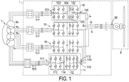
- FIG. 1 is a schematic circuit diagram of a wind power conversion system according to a first embodiment of the present invention.
- the wind power conversion system 1 is electrically connected between a wind power generator 8 and an isolating transformer T.
- a primary side of the isolating transformer T is electrically connected with an AC power network.
- the AC power from the wind power generator 8 may be converted by the wind power conversion system 1 and then transmitted to the AC power network through the isolating transformer T.
- the AC power received by the isolating transformer T may be converted by the wind power conversion system 1 and then transmitted to the wind power generator 8.
- the wind power conversion system 1 may convert and transmit the electric energy in a single direction or bilateral directions.
- the voltage levels of the wind power generator 8 and the AC power network are medium voltage levels, for example 1KV ⁇ 10KV.
- the wind power conversion system 1 comprises plural first converting circuits 10 and a second converting circuit 11.
- a first generator-side terminal 100 of each first converting circuit 10 is electrically connected with a power transmission terminal 80 of the wind power generator 8.
- a first network-side terminal 101 of each first converting circuit 10 is electrically connected with the corresponding secondary winding Np of the plural secondary windings Np of the isolating transformer T.
- the AC power from the wind power generator 8 is converted by each first converting circuit 10 and then transmitted to the AC power network through the isolating transformer T.
- the AC power received by the isolating transformer T may be converted by each first converting circuit 10 and then transmitted to the wind power generator 8.
- the second converting circuit 11 comprises plural second generator-side terminals 110.
- the plural second generator-side terminals 110 are electrically connected with the corresponding first generator-side terminals 100 of the plural first converting circuits 10 in series. That is, the plurality of second generator-side terminals 110 may correspond to the plurality of the first converting circuits 10 in a one-to-one ratio.
- the plural second generator-side terminals 110 are electrically connected with the corresponding phase windings of the power transmission terminal 80 of the wind power generator 8 through the corresponding first converting circuits 10.
- a second network-side terminal 111 of the second converting circuit 11 is electrically connected with the corresponding secondary winding Np of the plural secondary windings Np of the isolating transformer T.
- the second converting circuit 11 is selectively enabled or disabled.
- the AC power from the wind power generator 8 is converted by the second converting circuit 11 and then transmitted to the AC power network through the isolating transformer T.
- the AC power received by the isolating transformer T may be converted by the second converting circuit 11 and then transmitted to the wind power generator 8.
- the second converting circuit 11 is enabled, the power converting task of the plural first converting circuits 10 is shared by the second converting circuit 11. Consequently, the voltage stress applied to the plural first converting circuits 10 will be reduced.
- the wind power generator 8 is a (3N)-phase wind power generator, wherein N is a natural number.
- the wind power generator 8 is a three-phase wind power generator. Consequently, the power transmission terminal 80 of the wind power generator 8 comprises three phase windings. The three phase winding have respective phase voltages.
- the first generator-side terminals 100 of the first converting circuits 10 are electrically connected with the corresponding phase windings of the wind power generator 8.
- the wind power conversion system 1 comprises 3N first converting circuits 10. In this embodiment, the wind power conversion system 1 comprises three first converting circuits 10.
- the number of the secondary windings Np of the isolating transformer T is equal to the total number of the first converting circuits 10 and the second converting circuit 11. Since the wind power conversion system 1 of FIG. 1 comprises three first converting circuits 10 and one second converting circuit 11, the isolating transformer T has four secondary windings Np.
- each first converting circuit 10 is a three/single phase converting circuit.
- each first converting circuit 10 comprises a first generator-side converter 102, a first network-side converter 103 and a first DC bus storage unit 104.
- the first generator-side converter 102 has a first AC side and a first DC side.
- the first AC side is electrically connected with the first generator-side terminal 100 of the first converting circuit 10 and electrically connected with the wind power generator 8 through the first generator-side terminal 100.
- the first generator-side converter 102 is controlled by a pulse width modulation (PWM) method.
- PWM pulse width modulation
- the first AC side is served as the first generator-side terminal 100.
- the first network-side converter 103 has a second AC side and a second DC side.
- the second AC side is electrically connected with the corresponding secondary winding Np of the plural secondary windings Np of the isolating transformer T.
- the second AC side is served as the first network-side terminal 101.
- the first network-side converter 103 is also controlled by the PWM method.
- the first DC bus storage unit 104 comprises at least one bus capacitor.
- the first DC bus storage unit 104 is electrically connected between the first DC side of the first generator-side converter 102 and the second DC side of the first network-side converter 103.
- the first DC bus storage unit 104 is used for storing electric energy, so that the voltage difference across the first DC bus storage unit 104 is equal to a first DC voltage Vdc1. Since the first converting circuit 10 comprises the first generator-side converter 102, the first network-side converter 103 and the first DC bus storage unit 104, the first converting circuit 10 has an AC/DC/AC circuitry configuration.
- the first converting circuit 10 has a two-level circuitry configuration.
- the first generator-side converter 102 comprises two bridge arms. That is, the first generator-side converter 102 has a single-phase full-bridge two-level circuitry configuration.
- the two bridge arms are collaboratively defined as an H bridge.
- each bridge arm contains two serially-connected switch elements.
- An example of the switch element includes but is not limited to an insulated gate bipolar transistor (IGBT).
- the first network-side converter 103 has a three-phase full-bridge two-level circuitry configuration.
- the first network-side converter 103 comprises three bridge arms, including an A-phase bridge arm, a B-phase bridge arm and a C-phase bridge arm.
- each phase bridge arm contains two serially-connected switch elements.
- the first generator-side converter 102 further comprises a chopper circuit 105.
- the chopper circuit 105 is connected with the two bridge arms of the first generator-side converter 102 in parallel.
- the chopper circuit 105 comprises at least one switch element and at least one resistor, which are connected with each other in series.
- the chopper circuit 105 is used for inhibiting the voltage and current of the first converting circuit 10 in order to achieve a protecting purpose.
- the second converting circuit 11 is a three/three phase converting circuit.
- the second converting circuit 11 comprises a second generator-side converter 112, a second network-side converter 113 and a second DC bus storage unit 114.
- the second generator-side converter 112 has a third AC side and a third DC side.
- the third AC side is electrically connected with the plural second generator-side terminals 110 of the second converting circuit 11, serially connected with the corresponding first generator-side terminals 100 of the plural first converting circuits 10 through the plural second generator-side terminals 110, and electrically connected with the power transmission terminals 80 of the wind power generator 8.
- the second generator-side converter 112 is controlled by a pulse width modulation (PWM) method.
- PWM pulse width modulation
- the second network-side converter 113 has a fourth AC side and a fourth DC side.
- the fourth AC side is electrically connected with the corresponding secondary winding Np of the plural secondary windings Np of the isolating transformer T.
- the fourth AC side is served as the second network-side terminal 111.
- the second network-side converter 113 is also controlled by the PWM method.
- the second DC bus storage unit 114 comprises at least one bus capacitor.
- the second DC bus storage unit 114 is electrically connected between the third DC side of the second generator-side converter 112 and the fourth DC side of the second network-side converter 113.
- the second DC bus storage unit 114 is used for storing electric energy, so that the voltage difference across the second DC bus storage unit 114 is equal to a second DC voltage Vdc2. Since the second converting circuit 11 comprises the second generator-side converter 112, the second network-side converter 113 and the second DC bus storage unit 114, the second converting circuit 11 has an AC/DC/AC circuitry configuration.
- the second converting circuit 11 has a two-level circuitry configuration.
- the second generator-side converter 112 comprises three bridge arms, wherein each bride arm comprises two serially-connected switch elements. That is, the second generator-side converter 112 has a three-phase full-bridge two-level circuitry configuration.
- the second network-side converter 113 comprises three bridge arms, wherein each bride arm comprises two serially-connected switch elements. That is, the second network-side converter 113 also has a three-phase full-bridge two-level circuitry configuration.
- the node between the two serially-connected switch elements of each bridge arm of the second generator-side converter 112 is connected with the corresponding second generator-side terminal 110.
- the second generator-side converter 112 further comprises a chopper circuit.
- the function of the chopper circuit of the second generator-side converter 112 is similar to that of the chopper circuit 105 of the first generator-side converter 102, and is not redundantly described herein.
- first converting circuit and the second converting circuit may be made while retaining the teachings of the invention.
- some variant examples of the first converting circuit and the second converting circuit will be illustrated with reference to FIGS. 2 ⁇ 5 .
- Component parts and elements corresponding to those of the first embodiment are designated by identical numeral references, and detailed descriptions thereof are omitted.
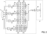
- FIG. 2 is a schematic circuit diagram of a wind power conversion system according to a second embodiment of the present invention.
- the first converting circuit 20 of the wind power conversion system 1 of this embodiment has a three-level circuitry configuration.
- the first generator-side converter 202 of the first converting circuit 20 has a single-phase full-bridge three-level circuitry configuration, and the first network-side converter 203 of the first converting circuit 20 has a three-phase three-level circuitry configuration.
- the second converting circuit 21 of the wind power conversion system 1 of this embodiment has a three-level circuitry configuration.
- the second generator-side converter 212 of the second converting circuit 21 has a three-phase full-bridge three-level circuitry configuration, and the second network-side converter 213 of the second converting circuit 21 has a three-phase three-level circuitry configuration.
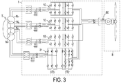
- FIG. 3 is a schematic circuit diagram of a wind power conversion system according to a third embodiment of the present invention.
- the second converting circuit 11 has the AC/DC/AC circuitry configuration.
- the second converting circuit 31 is a two stage matrix converting circuit. Consequently, the second converting circuit 31 has an AC/AC circuitry configuration.
- the second converting circuit 31 comprises a second generator-side converter 312 and a second network-side converter 313, but the second DC bus storage unit 114 of FIG. 1 is omitted.
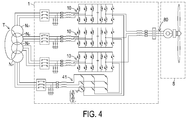
- FIG. 4 is a schematic circuit diagram of a wind power conversion system according to a fourth embodiment of the present invention.
- the second converting circuit 41 of this embodiment also has an AC/AC circuitry configuration.
- the second converting circuit 41 is a conventional matrix converting circuit.
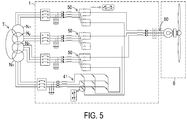
- FIG. 5 is a schematic circuit diagram of a wind power conversion system according to a fifth embodiment of the present invention.
- the first converting circuit 10 has the AC/DC/AC circuitry configuration.
- the first converting circuit 50 of this embodiment is a three/single phase matrix converting circuit. That is, the first converting circuit 50 has an AC/AC circuitry configuration.
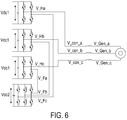
- FIG. 6 is a schematic circuit diagram illustrating a portion of the wind power conversion system of FIG. 1 .
- FIG. 7 is a schematic circuit diagram illustrating the simplified model of FIG. 6 .
- the voltages V_Fa, V_Fb and V_Fc are phase voltages at the A-phase second generator-side terminal 110, the B-phase second generator-side terminal 110 and the C-phase second generator-side terminal 110 of the second converting circuit 11, respectively.
- the voltage V_Ha is the output voltage from the first AC side of the first generator-side converter 102 of the first converting circuit 10 which is connected with the A-phase winding of the three phase windings of the wind power generator 8.
- the voltage V_Hb is the output voltage from the first AC side of the first generator-side converter 102 of the first converting circuit 10 which is connected with the B-phase winding of the three phase windings of the wind power generator 8.
- the voltage V_Hc is the output voltage from the first AC side of the first generator-side converter 102 of the first converting circuit 10 which is connected with the C-phase winding of the three phase windings of the wind power generator 8.
- the voltages V_Gen_a, V_Gen_b and V_Gen_c are the phase voltages of the A-phase winding, the B-phase winding and the C-phase winding of the three phase windings of the wind power generator 8, respectively.
- the voltage V_conv_a is the output voltage from the first generator-side terminal 100 of the first converting circuit 10 which is connected with the A-phase winding of the three phase windings of the wind power generator 8.
- the voltage V_conv_b is the output voltage from the first generator-side terminal 100 of the first converting circuit 10 which is connected with the B-phase winding of the three phase windings of the wind power generator 8.
- the voltage V_conv_c is the output voltage from the first generator-side terminal 100 of the first converting circuit 10 which is connected with the C-phase winding of the three phase windings of the wind power generator 8.
- S_Ha, S_Hb and S_Hc are the duty ratios of the switch elements of the bridge arms in the first generator-side converters 102 which are connected with the A-phase winding, the B-phase winding and the C-phase winding of the three phase windings of the wind power generator 8, respectively, and Vdc1 is the first DC voltage of the first DC bus storage unit 104.
- the first converting circuit is a matrix converting circuit (e.g. the matrix converting circuit of FIG. 5 )
- the first DC voltage Vdc1 is a virtual DC voltage.
- S_Fa, S_Fb and S_Fc are the duty ratios of the switch elements in the three bridge arms of the second generator-side converter 112 of the second converting circuit 21, respectively, and Vdc2 is the second DC voltage of the second DC bus storage unit 114.
- the second converting circuit is a matrix converting circuit (e.g. the matrix converting circuit of FIG. 3 or FIG. 4 )
- the second DC voltage Vdc2 is a virtual DC voltage.
- each second generator-side terminal 110 of the second converting circuit 11 is electrically connected with the corresponding first generator-side terminal 100 of the first converting circuit 10 in series, the output voltage from the first generator-side terminal 100 of the first converting circuit 10 and the output voltage from the corresponding second generator-side terminal 110 of the second converting circuit 11 are connected with each other in series.
- the sum of the phase voltage V_Fa and the output voltage V_Ha is equal to the A-phase output voltage V_conv_a of the first converting circuit 10
- the sum of the phase voltage V_Fb and the output voltage V_Hb is equal to the B-phase output voltage V_conv_b of the first converting circuit 10
- the sum of the phase voltage V_Fc and the output voltage V_Hc is equal to the C-phase output voltage V_conv_c of the first converting circuit 10.
- the wind power conversion system of the present invention may be applied to the wind power generator 8 at 3.3kV.
- the wind power conversion system 1 comprises the plural first converting circuits 10 and the second converting circuit 11.
- the plural second generator-side terminals 110 of the second converting circuit 11 are electrically connected with the corresponding first generator-side terminals 100 of the plural first converting circuits 10 in series.
- the second network-side terminal 111 of the second converting circuit 11 is electrically connected with the corresponding secondary winding Np of the plural secondary windings Np of the isolating transformer T.
- the overall cost of the wind power conversion system 1 is reduced.
- the power converting task of the plural first converting circuits 10 is shared by the second converting circuit 11, the voltage stress applied to the plural first converting circuits 10 will be reduced. Consequently, the power components (e.g. switch elements) with lower voltage-withstanding capacity (e.g. 1.7KV) may be used in the wind power conversion system 1 in order to control the wind power generator 8 at the medium voltage levels.
- the fabricating cost of the wind power conversion system 1 is largely reduced.
- the second converting circuit as shown in FIGS. 1 ⁇ 5 is selectively operated in a crowbar mode or a non-crowbar mode according to the result of comparing the phase voltage of each phase winding of the wind power generator 8 with the maximum output voltage of the corresponding first generator-side terminal 100 of the first converting circuit 10.
- the wind power conversion system 1 of FIG. 1 Take the wind power conversion system 1 of FIG. 1 as an example. If the phase voltage of each phase winding of the wind power generator 8 is lower than or equal to the maximum output voltage of the corresponding first generator-side terminal 100 of the first converting circuit 10, the second converting circuit 11 is operated in the crowbar mode. In the crowbar mode, the switching actions of all switch elements of the second converting circuit 11 are disabled.
- the second generator-side terminals 110 of the second converting circuit 11 are short-circuited. That is, when the second converting circuit 11 is operated in the crowbar mode, only the plural first converting circuits 10 of the wind power conversion system 1 are enabled to perform the power conversion between the wind power generator 8 and the AC power network. Since the second converting circuit 11 is disabled, the power consumption of the wind power conversion system 1 is reduced. On the other hand, if the phase voltage of one phase winding of the wind power generator 8 is higher than the maximum output voltage of the corresponding first generator-side terminal 100 of the first converting circuit 10, the second converting circuit 11 is operated in the non-crowbar mode. In the non-crowbar mode, the switching actions of all switch elements of the second converting circuit 11 are enabled.
- the power converting task of the plural first converting circuits 10 is shared by the second converting circuit 11.
- the phase voltage at each second generator-side terminal 110 is one half of the output voltage from the first generator-side terminal 100 of the corresponding first converting circuit 10.
- the wind power conversion system 1 further comprises a controlling circuit (not shown). Under control of the controlling circuit, the second converting circuit 11 is operated in the crowbar mode or the non-crowbar mode.
- the first generator-side converters 102 of the plural first converting circuits 10 and the second generator-side converter 112 of the second converting circuit 11 of the wind power conversion system as shown in FIG. 1 , 2 , 3 or 4 may be controlled by a sinusoidal pulse width modulation (SPWM) method based on a carrier phase-shifting technique.
- SPWM sinusoidal pulse width modulation
- the phase shift angle for the carrier phase-shifting technique may be determined according to the circuitry configuration and the operating mode of the second converting circuit.
- FIG. 8 is a schematic waveform diagram illustrating the associated signals of the A-phase circuit of the wind power conversion system of FIG. 1 in a first carrier phase-shifting mode and with the SPWM control.
- FIG. 9 is a schematic waveform diagram illustrating the associated signals of the A-phase circuit of the wind power conversion system of FIG. 1 in a second carrier phase-shifting mode and with the SPWM control.
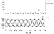
- FIG. 10 is a schematic waveform diagram illustrating the three phase currents (ia, ib, ic) and the current spectrum of the two-level first converting circuit or the two-level second converting circuit in the first carrier phase-shifting mode and with the SPWM control.
- FIG. 8 is a schematic waveform diagram illustrating the associated signals of the A-phase circuit of the wind power conversion system of FIG. 1 in a first carrier phase-shifting mode and with the SPWM control.
- FIG. 9 is a schematic waveform diagram illustrating the associated signals of the A-phase circuit of the wind power conversion system of FIG. 1 in a second carrier
- FIG. 11 is a schematic waveform diagram illustrating the three phase currents and the current spectrum of the two-level first converting circuit or the two-level second converting circuit in the first carrier phase-shifting mode and without the SPWM control.
- FIG. 12 is a schematic waveform diagram illustrating the three phase currents and the current spectrum of the two-level first converting circuit or the two-level second converting circuit in the second carrier phase-shifting mode and with the SPWM control.
- FIG. 13 is a schematic waveform diagram illustrating the three phase currents and the current spectrum of the two-level first converting circuit or the two-level second converting circuit in the second carrier phase-shifting mode and without the SPWM control.
- the first converting circuits and the second converting circuit have the AC/DC/AC circuitry configurations. If the second converting circuit is operated in the non-crowbar mode, the phase shift angles among the carrier waves of the two bridge arms of the first generator-side converter of the first converting circuit (e.g. the H bridge) and the corresponding bridge arm of the second converting circuit (e.g. the three-phase full bridge) are 120°. In FIG.
- tri1 denotes the carrier wave of the left bridge arm of the first generator-side converter of the first converting circuit
- tri2 denotes the carrier wave of the right bridge arm of the first generator-side converter of the first converting circuit
- tri3 denotes the carrier wave of the corresponding bridge arm of the second generator-side converter of the second converting circuit.
- the phase shift angles among tri1, tri2 and tri3 are 120°, and the modulated waves S_a of them are identical.
- the linear voltage Vab outputted by the first converting circuit has seven levels.
- the modulation result of FIG. 11 i.e.
- the modulation result of FIG. 10 indicates that the transient voltage response and the harmonic voltages at the first generator-side terminals 100 of the first converting circuit 10 and the second generator-side terminals 110 of the second converting circuit 11 are reduced.
- the first converting circuit and the second converting circuit have the AC/DC/AC circuitry configurations (i.e.
- the second converting circuit 11 is operated in the crowbar mode
- only the first generator-side converters 102 of the plural first converting circuits 10 are controlled by the SPWM method based on the carrier phase-shifting technique because the second converting circuit 11 is disabled.
- the phase shift angle between the carrier waves of the two bridge arms of the first generator-side converter of the first converting circuit is 180°.
- the transient voltage response and the harmonic voltages at the first generator-side terminals 100 of the first converting circuit 10 and the second generator-side terminals 110 of the second converting circuit 11 are reduced.
- the first converting circuits In the first carrier phase-shifting mode, the first converting circuits have the AC/DC/AC circuitry configurations, and the second converting circuit has the AC/AC circuitry configuration.
- the first generator-side converters 102 of the plural first converting circuits 10 are controlled by the SPWM method based on the carrier phase-shifting technique. Regardless of whether the second converting circuit is operated in the crowbar mode or the non-crowbar mode, the phase shift angle between the carrier waves of the two bridge arms of the first generator-side converter of the first converting circuit is 180°. In FIG.
- tri1 denotes the carrier wave of the left bridge arm of the first generator-side converter of the first converting circuit
- tri2 denotes the carrier wave of the right bridge arm of the first generator-side converter of the first converting circuit.
- the modulated wave S_a is identical.
- the linear voltage Vab outputted by the first converting circuit has five levels.
- the modulation result of FIG. 12 i.e. in the second carrier phase-shifting mode and without the SPWM control
- the amplitude modulation ratio in the crowbar mode is 1.5 times the amplitude modulation ratio in the non-crowbar mode. Consequently, the harmonic component is further reduced.
- the present invention provides a wind power conversion system.
- the wind power conversion system comprises plural first converting circuits and a second converting circuit.
- the plural second generator-side terminals of the second converting circuit are electrically connected with the corresponding first generator-side terminals of the plural first converting circuits in series.
- the second network-side terminal of the second converting circuit is electrically connected with the corresponding secondary winding of the plural secondary windings of an isolating transformer.
- the power components with lower voltage-withstanding capacity may be used in the wind power conversion system in order to control the wind power generator at the medium voltage levels.
- the fabricating cost of the wind power conversion system is largely reduced.
- the second converting circuit is selectively operated in a crowbar mode or a non-crowbar mode according to the result of comparing the phase voltage of each phase winding of the wind power generator with the output voltage of the corresponding first generator-side terminal of the first converting circuit. When the second converting circuit is operated in the crowbar mode, the second converting circuit is disabled, so that the power consumption of the wind power conversion system is reduced.
- the power converting task of the plural first converting circuits is shared by the second converting circuit.
- the first generator-side converters of the plural first converting circuits and the second generator-side converter of the second converting circuit may be controlled by a sinusoidal pulse width modulation (SPWM) method based on a carrier phase-shifting technique. Consequently, the transient voltage response and the harmonic voltages at the first generator-side terminals of the first converting circuit and the second generator-side terminals of the second converting circuit will be minimized.
- SPWM sinusoidal pulse width modulation
Landscapes
- Engineering & Computer Science (AREA)
- Power Engineering (AREA)
- Control Of Eletrric Generators (AREA)
- Inverter Devices (AREA)
Abstract
Description
- The present invention relates to a wind power conversion system, and more particularly to a wind power conversion system that is easily controlled and cost-effective.
- Nowadays, the energy crisis problem becomes more serious. With increasing environmental consciousness, there are growing demands on renewable energy. For example, solar energy and wind power are the well-known power sources of the renewable energy. In the conventional renewable power generation system, the frequency and the amplitude of the AC power outputted by the power generator are different from the frequency and the amplitude of the AC power network. Consequently, a converting circuit is required to convert the AC power outputted by the power generator. By the converting circuit, the frequency and the amplitude of the AC power outputted by the power generator are identical to those of the AC power of the AC power network. Then, the converted AC power is transmitted to the AC power network through an isolating transformer. As a consequence, the purpose of the grid connected power generation can be achieved.
- For example, the wind power conversion system operated in the medium voltage levels (e.g. 1KV∼10KV) usually has the following circuitry configurations. The first type is a cascade circuitry configuration of plural power components. The second type is a multi-level (e.g. three-level or more than three-level) circuitry configuration of plural serially-connected power components with lower voltage withstanding capacity (e.g. 1.7KV). The third type is a multi-level (e.g. two-level or more than two-level) circuitry configuration of plural serially connected power components with higher voltage withstanding capacity (e.g. 3.3KV, 4.5KV or 6KV).
- The first type wind power conversion system comprises plural converting circuits (e.g. at least six converting circuits) in cascade connection. For complying with plural independent DC bus lines in the plural converting circuits, the isolating transformer between the AC power network and the wind power conversion system has plural secondary windings (e.g. at least six secondary windings) to be electrically connected with the plural converting circuits. Under this circumstance, the overall cost associated with the factory or instrument is high. Although the second type wind power conversion system comprises plural serially-connected power components (e.g. switch elements) with lower voltage withstanding capacity, more power components are required to produce the multi-level circuitry configuration. Consequently, the method of controlling the power components is more complicated. Moreover, since more power components are employed, the fabricating cost is high. The two-level circuitry configuration of the third type wind power conversion system uses less power components. However, since the power components have higher voltage withstanding capacity, the fabricating cost of the third type wind power conversion system is increased due to the increased cost of using the power components having higher voltage withstanding capacity.
- Therefore, there is a need of providing an improved wind power conversion system in order to overcome the above drawbacks.
- An object of the present invention provides a wind power conversion system. The wind power conversion system comprises plural first converting circuits and a second converting circuit. The plural second generator-side terminals of the second converting circuit are electrically connected with the corresponding first generator-side terminals of the plural first converting circuits in series. The second network-side terminal of the second converting circuit is electrically connected with the corresponding secondary winding of the plural secondary windings of an isolating transformer. By means of the circuitry configuration of the wind power conversion system, the number of the secondary windings of the isolating transformer is reduced. Moreover, since the power converting task of the plural first converting circuits is shared by the second converting circuit, the voltage stress applied to the plural first converting circuits will be reduced. Consequently, the power components with lower voltage-withstanding capacity may be used in the wind power conversion system in order to control the wind power generator at the medium voltage levels.
- Another object of the present invention provides a wind power conversion system. The second converting circuit is selectively operated in a crowbar mode or a non-crowbar mode according to the result of comparing the phase voltage of each phase winding of the wind power generator with the maximum output voltage of the corresponding first generator-side terminal of the first converting circuit. When the second converting circuit is operated in the crowbar mode, the second converting circuit is disabled, so that the power consumption of the wind power conversion system is reduced. When the second converting circuit is operated in the non-crowbar mode, the power converting task of the plural first converting circuits is shared by the second converting circuit.
- A further object of the present invention provides a wind power conversion system. The first generator-side converters of the plural first converting circuits and the second generator-side converter of the second converting circuit may be controlled by a sinusoidal pulse width modulation (SPWM) method based on a carrier phase-shifting technique. Consequently, the transient voltage response and the harmonic voltages at the first generator-side terminals of the first converting circuit and the second generator-side terminals of the second converting circuit will be minimized.
- In accordance with an aspect of the present invention, there is provided a wind power conversion system. The wind power conversion system is electrically connected between a wind power generator and an isolating transformer. The wind power conversion system includes plural first converting circuits and a second converting circuit. The plural first converting circuits perform a power converting task, and include respective first generator-side terminals and respective first network-side terminals. The first generator-side terminals are electrically connected with the wind power generator. The first network-side terminals are electrically connected with corresponding secondary windings of plural secondary windings of the isolating transformer. The second converting circuit includes plural second generator-side terminals and a second network-side terminal. The second network-side terminal is electrically connected with the corresponding secondary winding of plural secondary windings of the isolating transformer. The second generator-side terminals are serially connected with the corresponding first generator-side terminals of the first converting circuits and electrically connected with the wind power generator through the first converting circuits. The second converting circuit is selectively enabled or disabled. When the second converting circuit is enabled, the power converting task of the plural first converting circuits is shared by the second converting circuit.
- The above contents of the present invention will become more readily apparent to those ordinarily skilled in the art after reviewing the following detailed description and accompanying drawings.
-
-
FIG. 1 is a schematic circuit diagram of a wind power conversion system according to a first embodiment of the present invention; -
FIG. 2 is a schematic circuit diagram of a wind power conversion system according to a second embodiment of the present invention; -
FIG. 3 is a schematic circuit diagram of a wind power conversion system according to a third embodiment of the present invention; -
FIG. 4 is a schematic circuit diagram of a wind power conversion system according to a fourth embodiment of the present invention; -
FIG. 5 is a schematic circuit diagram of a wind power conversion system according to a fifth embodiment of the present invention; -
FIG. 6 is a schematic circuit diagram illustrating a portion of the wind power conversion system ofFIG. 1 ; -
FIG. 7 is a schematic circuit diagram illustrating the simplified model ofFIG. 6 ; -
FIG. 8 is a schematic waveform diagram illustrating the associated signals of the A-phase circuit of the wind power conversion system ofFIG. 1 in a first carrier phase-shifting mode and with the SPWM control; -
FIG. 9 is a schematic waveform diagram illustrating the associated signals of the A-phase circuit of the wind power conversion system ofFIG. 1 in a second carrier phase-shifting mode and with the SPWM control; -
FIG. 10 is a schematic waveform diagram illustrating the three phase currents and the current spectrum of the two-level first converting circuit or the two-level second converting circuit in the first carrier phase-shifting mode and with the SPWM control; -
FIG. 11 is a schematic waveform diagram illustrating the three phase currents and the current spectrum of the two-level first converting circuit or the two-level second converting circuit in the first carrier phase-shifting mode and without the SPWM control; -
FIG. 12 is a schematic waveform diagram illustrating the three phase currents and the current spectrum of the two-level first converting circuit or the two-level second converting circuit in the second carrier phase-shifting mode and with the SPWM control; and -
FIG. 13 is a schematic waveform diagram illustrating the three phase currents and the current spectrum of the two-level first converting circuit or the two-level second converting circuit in the second carrier phase-shifting mode and without the SPWM control. - The present invention will now be described more specifically with reference to the following embodiments. It is to be noted that the following descriptions of preferred embodiments of this invention are presented herein for purpose of illustration and description only. It is not intended to be exhaustive or to be limited to the precise form disclosed.
-
FIG. 1 is a schematic circuit diagram of a wind power conversion system according to a first embodiment of the present invention. As shown inFIG. 1 , the windpower conversion system 1 is electrically connected between awind power generator 8 and an isolating transformer T. A primary side of the isolating transformer T is electrically connected with an AC power network. In this embodiment, the AC power from thewind power generator 8 may be converted by the windpower conversion system 1 and then transmitted to the AC power network through the isolating transformer T. Optionally, the AC power received by the isolating transformer T may be converted by the windpower conversion system 1 and then transmitted to thewind power generator 8. In other words, the windpower conversion system 1 may convert and transmit the electric energy in a single direction or bilateral directions. - In this embodiment, the voltage levels of the
wind power generator 8 and the AC power network are medium voltage levels, for example 1KV∼10KV. - As shown in
FIG. 1 , the windpower conversion system 1 comprises plural first convertingcircuits 10 and a second convertingcircuit 11. A first generator-side terminal 100 of each first convertingcircuit 10 is electrically connected with apower transmission terminal 80 of thewind power generator 8. A first network-side terminal 101 of each first convertingcircuit 10 is electrically connected with the corresponding secondary winding Np of the plural secondary windings Np of the isolating transformer T. The AC power from thewind power generator 8 is converted by each first convertingcircuit 10 and then transmitted to the AC power network through the isolating transformer T. Optionally, the AC power received by the isolating transformer T may be converted by each first convertingcircuit 10 and then transmitted to thewind power generator 8. - The second converting
circuit 11 comprises plural second generator-side terminals 110. The plural second generator-side terminals 110 are electrically connected with the corresponding first generator-side terminals 100 of the plural first convertingcircuits 10 in series. That is, the plurality of second generator-side terminals 110 may correspond to the plurality of the first convertingcircuits 10 in a one-to-one ratio. Moreover, the plural second generator-side terminals 110 are electrically connected with the corresponding phase windings of thepower transmission terminal 80 of thewind power generator 8 through the corresponding first convertingcircuits 10. A second network-side terminal 111 of the second convertingcircuit 11 is electrically connected with the corresponding secondary winding Np of the plural secondary windings Np of the isolating transformer T. The second convertingcircuit 11 is selectively enabled or disabled. When the second convertingcircuit 11 is enabled, the AC power from thewind power generator 8 is converted by the second convertingcircuit 11 and then transmitted to the AC power network through the isolating transformer T. Optionally, the AC power received by the isolating transformer T may be converted by the second convertingcircuit 11 and then transmitted to thewind power generator 8. In other words, when the second convertingcircuit 11 is enabled, the power converting task of the plural first convertingcircuits 10 is shared by the second convertingcircuit 11. Consequently, the voltage stress applied to the plural first convertingcircuits 10 will be reduced. - In accordance with the present invention, the
wind power generator 8 is a (3N)-phase wind power generator, wherein N is a natural number. In this embodiment, thewind power generator 8 is a three-phase wind power generator. Consequently, thepower transmission terminal 80 of thewind power generator 8 comprises three phase windings. The three phase winding have respective phase voltages. The first generator-side terminals 100 of the first convertingcircuits 10 are electrically connected with the corresponding phase windings of thewind power generator 8. Correspondingly, the windpower conversion system 1 comprises 3N first convertingcircuits 10. In this embodiment, the windpower conversion system 1 comprises three first convertingcircuits 10. The number of the secondary windings Np of the isolating transformer T is equal to the total number of the first convertingcircuits 10 and the second convertingcircuit 11. Since the windpower conversion system 1 ofFIG. 1 comprises three first convertingcircuits 10 and one second convertingcircuit 11, the isolating transformer T has four secondary windings Np. - Moreover, each first converting
circuit 10 is a three/single phase converting circuit. In this embodiment, each first convertingcircuit 10 comprises a first generator-side converter 102, a first network-side converter 103 and a first DCbus storage unit 104. The first generator-side converter 102 has a first AC side and a first DC side. The first AC side is electrically connected with the first generator-side terminal 100 of the first convertingcircuit 10 and electrically connected with thewind power generator 8 through the first generator-side terminal 100. The first generator-side converter 102 is controlled by a pulse width modulation (PWM) method. Moreover, the first AC side is served as the first generator-side terminal 100. The first network-side converter 103 has a second AC side and a second DC side. The second AC side is electrically connected with the corresponding secondary winding Np of the plural secondary windings Np of the isolating transformer T. The second AC side is served as the first network-side terminal 101. Moreover, the first network-side converter 103 is also controlled by the PWM method. In this embodiment, the first DCbus storage unit 104 comprises at least one bus capacitor. The first DCbus storage unit 104 is electrically connected between the first DC side of the first generator-side converter 102 and the second DC side of the first network-side converter 103. Moreover, the first DCbus storage unit 104 is used for storing electric energy, so that the voltage difference across the first DCbus storage unit 104 is equal to a first DC voltage Vdc1. Since the first convertingcircuit 10 comprises the first generator-side converter 102, the first network-side converter 103 and the first DCbus storage unit 104, the first convertingcircuit 10 has an AC/DC/AC circuitry configuration. - In the embodiment of
FIG. 1 , the first convertingcircuit 10 has a two-level circuitry configuration. Moreover, the first generator-side converter 102 comprises two bridge arms. That is, the first generator-side converter 102 has a single-phase full-bridge two-level circuitry configuration. Moreover, the two bridge arms are collaboratively defined as an H bridge. And each bridge arm contains two serially-connected switch elements. An example of the switch element includes but is not limited to an insulated gate bipolar transistor (IGBT). The first network-side converter 103 has a three-phase full-bridge two-level circuitry configuration. Moreover, the first network-side converter 103 comprises three bridge arms, including an A-phase bridge arm, a B-phase bridge arm and a C-phase bridge arm. And each phase bridge arm contains two serially-connected switch elements. Moreover, the first generator-side converter 102 further comprises achopper circuit 105. Thechopper circuit 105 is connected with the two bridge arms of the first generator-side converter 102 in parallel. In this embodiment, thechopper circuit 105 comprises at least one switch element and at least one resistor, which are connected with each other in series. Thechopper circuit 105 is used for inhibiting the voltage and current of the first convertingcircuit 10 in order to achieve a protecting purpose. - Moreover, the second converting
circuit 11 is a three/three phase converting circuit. In this embodiment, the second convertingcircuit 11 comprises a second generator-side converter 112, a second network-side converter 113 and a second DCbus storage unit 114. The second generator-side converter 112 has a third AC side and a third DC side. The third AC side is electrically connected with the plural second generator-side terminals 110 of the second convertingcircuit 11, serially connected with the corresponding first generator-side terminals 100 of the plural first convertingcircuits 10 through the plural second generator-side terminals 110, and electrically connected with thepower transmission terminals 80 of thewind power generator 8. The second generator-side converter 112 is controlled by a pulse width modulation (PWM) method. The second network-side converter 113 has a fourth AC side and a fourth DC side. The fourth AC side is electrically connected with the corresponding secondary winding Np of the plural secondary windings Np of the isolating transformer T. The fourth AC side is served as the second network-side terminal 111. Moreover, the second network-side converter 113 is also controlled by the PWM method. In this embodiment, the second DCbus storage unit 114 comprises at least one bus capacitor. The second DCbus storage unit 114 is electrically connected between the third DC side of the second generator-side converter 112 and the fourth DC side of the second network-side converter 113. Moreover, the second DCbus storage unit 114 is used for storing electric energy, so that the voltage difference across the second DCbus storage unit 114 is equal to a second DC voltage Vdc2. Since the second convertingcircuit 11 comprises the second generator-side converter 112, the second network-side converter 113 and the second DCbus storage unit 114, the second convertingcircuit 11 has an AC/DC/AC circuitry configuration. - In the embodiment of
FIG. 1 , the second convertingcircuit 11 has a two-level circuitry configuration. Moreover, the second generator-side converter 112 comprises three bridge arms, wherein each bride arm comprises two serially-connected switch elements. That is, the second generator-side converter 112 has a three-phase full-bridge two-level circuitry configuration. Moreover, the second network-side converter 113 comprises three bridge arms, wherein each bride arm comprises two serially-connected switch elements. That is, the second network-side converter 113 also has a three-phase full-bridge two-level circuitry configuration. Moreover, the node between the two serially-connected switch elements of each bridge arm of the second generator-side converter 112 is connected with the corresponding second generator-side terminal 110. Moreover, the second generator-side converter 112 further comprises a chopper circuit. The function of the chopper circuit of the second generator-side converter 112 is similar to that of thechopper circuit 105 of the first generator-side converter 102, and is not redundantly described herein. - It is noted that numerous modifications and alterations of the first converting circuit and the second converting circuit may be made while retaining the teachings of the invention. Hereinafter, some variant examples of the first converting circuit and the second converting circuit will be illustrated with reference to
FIGS. 2∼5 . Component parts and elements corresponding to those of the first embodiment are designated by identical numeral references, and detailed descriptions thereof are omitted. -
FIG. 2 is a schematic circuit diagram of a wind power conversion system according to a second embodiment of the present invention. In comparison withFIG. 1 , the first convertingcircuit 20 of the windpower conversion system 1 of this embodiment has a three-level circuitry configuration. The first generator-side converter 202 of the first convertingcircuit 20 has a single-phase full-bridge three-level circuitry configuration, and the first network-side converter 203 of the first convertingcircuit 20 has a three-phase three-level circuitry configuration. In comparison withFIG. 1 , the second convertingcircuit 21 of the windpower conversion system 1 of this embodiment has a three-level circuitry configuration. The second generator-side converter 212 of the second convertingcircuit 21 has a three-phase full-bridge three-level circuitry configuration, and the second network-side converter 213 of the second convertingcircuit 21 has a three-phase three-level circuitry configuration. -
FIG. 3 is a schematic circuit diagram of a wind power conversion system according to a third embodiment of the present invention. In the embodiment ofFIG. 1 , the second convertingcircuit 11 has the AC/DC/AC circuitry configuration. In this embodiment, the second convertingcircuit 31 is a two stage matrix converting circuit. Consequently, the second convertingcircuit 31 has an AC/AC circuitry configuration. In this embodiment, the second convertingcircuit 31 comprises a second generator-side converter 312 and a second network-side converter 313, but the second DCbus storage unit 114 ofFIG. 1 is omitted. -
FIG. 4 is a schematic circuit diagram of a wind power conversion system according to a fourth embodiment of the present invention. Like the second convertingcircuit 31 ofFIG. 3 , the second convertingcircuit 41 of this embodiment also has an AC/AC circuitry configuration. However, the second convertingcircuit 41 is a conventional matrix converting circuit. -
FIG. 5 is a schematic circuit diagram of a wind power conversion system according to a fifth embodiment of the present invention. In the embodiment ofFIG. 4 , the first convertingcircuit 10 has the AC/DC/AC circuitry configuration. In comparison withFIG. 4 , the first convertingcircuit 50 of this embodiment is a three/single phase matrix converting circuit. That is, the first convertingcircuit 50 has an AC/AC circuitry configuration. - Hereinafter, the performance of the wind
power conversion system 1 of the present invention will be illustrated with reference toFIGS. 1 ,6 and7 .FIG. 6 is a schematic circuit diagram illustrating a portion of the wind power conversion system ofFIG. 1 .FIG. 7 is a schematic circuit diagram illustrating the simplified model ofFIG. 6 . As shown inFIGS. 6 and7 , the voltages V_Fa, V_Fb and V_Fc are phase voltages at the A-phase second generator-side terminal 110, the B-phase second generator-side terminal 110 and the C-phase second generator-side terminal 110 of the second convertingcircuit 11, respectively. The voltage V_Ha is the output voltage from the first AC side of the first generator-side converter 102 of the first convertingcircuit 10 which is connected with the A-phase winding of the three phase windings of thewind power generator 8. The voltage V_Hb is the output voltage from the first AC side of the first generator-side converter 102 of the first convertingcircuit 10 which is connected with the B-phase winding of the three phase windings of thewind power generator 8. The voltage V_Hc is the output voltage from the first AC side of the first generator-side converter 102 of the first convertingcircuit 10 which is connected with the C-phase winding of the three phase windings of thewind power generator 8. The voltages V_Gen_a, V_Gen_b and V_Gen_c are the phase voltages of the A-phase winding, the B-phase winding and the C-phase winding of the three phase windings of thewind power generator 8, respectively. The voltage V_conv_a is the output voltage from the first generator-side terminal 100 of the first convertingcircuit 10 which is connected with the A-phase winding of the three phase windings of thewind power generator 8. The voltage V_conv_b is the output voltage from the first generator-side terminal 100 of the first convertingcircuit 10 which is connected with the B-phase winding of the three phase windings of thewind power generator 8. The voltage V_conv_c is the output voltage from the first generator-side terminal 100 of the first convertingcircuit 10 which is connected with the C-phase winding of the three phase windings of thewind power generator 8. - The output voltages V_Ha, V_Hb and V_Hc from the three first converting
circuits 10 may be expressed by the following formulae:


- In the above formulae, S_Ha, S_Hb and S_Hc are the duty ratios of the switch elements of the bridge arms in the first generator-
side converters 102 which are connected with the A-phase winding, the B-phase winding and the C-phase winding of the three phase windings of thewind power generator 8, respectively, and Vdc1 is the first DC voltage of the first DCbus storage unit 104. In case that the first converting circuit is a matrix converting circuit (e.g. the matrix converting circuit ofFIG. 5 ), the first DC voltage Vdc1 is a virtual DC voltage. - The phase voltages V_Fa, V_Fb and V_Fc from the second converting
circuit 11 may be expressed by the following formulae:


- In the above formulae, S_Fa, S_Fb and S_Fc are the duty ratios of the switch elements in the three bridge arms of the second generator-
side converter 112 of the second convertingcircuit 21, respectively, and Vdc2 is the second DC voltage of the second DCbus storage unit 114. In case that the second converting circuit is a matrix converting circuit (e.g. the matrix converting circuit ofFIG. 3 orFIG. 4 ), the second DC voltage Vdc2 is a virtual DC voltage. - Since each second generator-
side terminal 110 of the second convertingcircuit 11 is electrically connected with the corresponding first generator-side terminal 100 of the first convertingcircuit 10 in series, the output voltage from the first generator-side terminal 100 of the first convertingcircuit 10 and the output voltage from the corresponding second generator-side terminal 110 of the second convertingcircuit 11 are connected with each other in series. Consequently, the sum of the phase voltage V_Fa and the output voltage V_Ha is equal to the A-phase output voltage V_conv_a of the first convertingcircuit 10, the sum of the phase voltage V_Fb and the output voltage V_Hb is equal to the B-phase output voltage V_conv_b of the first convertingcircuit 10, and the sum of the phase voltage V_Fc and the output voltage V_Hc is equal to the C-phase output voltage V_conv_c of the first convertingcircuit 10. If Vdc1=Vdc2 and S_Hx=S_Fx (x=a, b, c), the output voltages V_conv_a, V_conv_b and V_conv_c may be expressed by the following formulae:


- From the above formulae, if Vdc1=2000V and the duty ratio is the largest, the maximum linear voltage outputted from each first converting
circuit 10 is equal to
- Consequently, the wind power conversion system of the present invention may be applied to the
wind power generator 8 at 3.3kV. - From the above descriptions, the wind
power conversion system 1 comprises the plural first convertingcircuits 10 and the second convertingcircuit 11. The plural second generator-side terminals 110 of the second convertingcircuit 11 are electrically connected with the corresponding first generator-side terminals 100 of the plural first convertingcircuits 10 in series. The second network-side terminal 111 of the second convertingcircuit 11 is electrically connected with the corresponding secondary winding Np of the plural secondary windings Np of the isolating transformer T. By means of the circuitry configuration of the wind power conversion system, the number of the secondary windings Np of the isolating transformer T is reduced. For example, as shown inFIG. 1 , the isolating transformer T comprises only four secondary windings Np. Consequently, the overall cost of the windpower conversion system 1 is reduced. Moreover, since the power converting task of the plural first convertingcircuits 10 is shared by the second convertingcircuit 11, the voltage stress applied to the plural first convertingcircuits 10 will be reduced. Consequently, the power components (e.g. switch elements) with lower voltage-withstanding capacity (e.g. 1.7KV) may be used in the windpower conversion system 1 in order to control thewind power generator 8 at the medium voltage levels. Moreover, since the number of the power components used in the windpower conversion system 1 is reduced and the power components have the lower voltage-withstanding capacity, the fabricating cost of the windpower conversion system 1 is largely reduced. - In some embodiments, the second converting circuit as shown in
FIGS. 1∼5 is selectively operated in a crowbar mode or a non-crowbar mode according to the result of comparing the phase voltage of each phase winding of thewind power generator 8 with the maximum output voltage of the corresponding first generator-side terminal 100 of the first convertingcircuit 10. Take the windpower conversion system 1 ofFIG. 1 as an example. If the phase voltage of each phase winding of thewind power generator 8 is lower than or equal to the maximum output voltage of the corresponding first generator-side terminal 100 of the first convertingcircuit 10, the second convertingcircuit 11 is operated in the crowbar mode. In the crowbar mode, the switching actions of all switch elements of the second convertingcircuit 11 are disabled. Under this circumstance, the second generator-side terminals 110 of the second convertingcircuit 11 are short-circuited. That is, when the second convertingcircuit 11 is operated in the crowbar mode, only the plural first convertingcircuits 10 of the windpower conversion system 1 are enabled to perform the power conversion between thewind power generator 8 and the AC power network. Since the second convertingcircuit 11 is disabled, the power consumption of the windpower conversion system 1 is reduced. On the other hand, if the phase voltage of one phase winding of thewind power generator 8 is higher than the maximum output voltage of the corresponding first generator-side terminal 100 of the first convertingcircuit 10, the second convertingcircuit 11 is operated in the non-crowbar mode. In the non-crowbar mode, the switching actions of all switch elements of the second convertingcircuit 11 are enabled. Consequently, the power converting task of the plural first convertingcircuits 10 is shared by the second convertingcircuit 11. In an embodiment, the phase voltage at each second generator-side terminal 110 is one half of the output voltage from the first generator-side terminal 100 of the corresponding first convertingcircuit 10. - Moreover, the wind
power conversion system 1 further comprises a controlling circuit (not shown). Under control of the controlling circuit, the second convertingcircuit 11 is operated in the crowbar mode or the non-crowbar mode. For reducing the transient voltage response (dv/dt) and the harmonic voltages at the first generator-side terminals 100 of the first convertingcircuit 10 and the second generator-side terminals 110 of the second convertingcircuit 11, the first generator-side converters 102 of the plural first convertingcircuits 10 and the second generator-side converter 112 of the second convertingcircuit 11 of the wind power conversion system as shown inFIG. 1 ,2 ,3 or4 may be controlled by a sinusoidal pulse width modulation (SPWM) method based on a carrier phase-shifting technique. Moreover, the phase shift angle for the carrier phase-shifting technique may be determined according to the circuitry configuration and the operating mode of the second converting circuit. - The benefits of the SPWM control will be illustrated with reference to
FIGS. 8∼13 .FIG. 8 is a schematic waveform diagram illustrating the associated signals of the A-phase circuit of the wind power conversion system ofFIG. 1 in a first carrier phase-shifting mode and with the SPWM control.FIG. 9 is a schematic waveform diagram illustrating the associated signals of the A-phase circuit of the wind power conversion system ofFIG. 1 in a second carrier phase-shifting mode and with the SPWM control.FIG. 10 is a schematic waveform diagram illustrating the three phase currents (ia, ib, ic) and the current spectrum of the two-level first converting circuit or the two-level second converting circuit in the first carrier phase-shifting mode and with the SPWM control.FIG. 11 is a schematic waveform diagram illustrating the three phase currents and the current spectrum of the two-level first converting circuit or the two-level second converting circuit in the first carrier phase-shifting mode and without the SPWM control.FIG. 12 is a schematic waveform diagram illustrating the three phase currents and the current spectrum of the two-level first converting circuit or the two-level second converting circuit in the second carrier phase-shifting mode and with the SPWM control.FIG. 13 is a schematic waveform diagram illustrating the three phase currents and the current spectrum of the two-level first converting circuit or the two-level second converting circuit in the second carrier phase-shifting mode and without the SPWM control. - In the first carrier phase-shifting mode, the first converting circuits and the second converting circuit have the AC/DC/AC circuitry configurations. If the second converting circuit is operated in the non-crowbar mode, the phase shift angles among the carrier waves of the two bridge arms of the first generator-side converter of the first converting circuit (e.g. the H bridge) and the corresponding bridge arm of the second converting circuit (e.g. the three-phase full bridge) are 120°. In
FIG. 8 , tri1 denotes the carrier wave of the left bridge arm of the first generator-side converter of the first converting circuit, tri2 denotes the carrier wave of the right bridge arm of the first generator-side converter of the first converting circuit, and tri3 denotes the carrier wave of the corresponding bridge arm of the second generator-side converter of the second converting circuit. According to the A-phase circuit modulation result ofFIG. 8 , the phase shift angles among tri1, tri2 and tri3 are 120°, and the modulated waves S_a of them are identical. By this modulation method, the linear voltage Vab outputted by the first converting circuit has seven levels. In comparison with the modulation result ofFIG. 11 (i.e. in the first carrier phase-shifting mode and without the SPWM control), the modulation result ofFIG. 10 (i.e. in the first carrier phase-shifting mode and with the SPWM control) indicates that the transient voltage response and the harmonic voltages at the first generator-side terminals 100 of the first convertingcircuit 10 and the second generator-side terminals 110 of the second convertingcircuit 11 are reduced. On the other hand, if the first converting circuit and the second converting circuit have the AC/DC/AC circuitry configurations (i.e. in the first carrier phase-shifting mode) and the second converting circuit is operated in the crowbar mode, only the first generator-side converters 102 of the plural first convertingcircuits 10 are controlled by the SPWM method based on the carrier phase-shifting technique because the second convertingcircuit 11 is disabled. Under this circumstance, the phase shift angle between the carrier waves of the two bridge arms of the first generator-side converter of the first converting circuit is 180°. Similarly, the transient voltage response and the harmonic voltages at the first generator-side terminals 100 of the first convertingcircuit 10 and the second generator-side terminals 110 of the second convertingcircuit 11 are reduced. - In the first carrier phase-shifting mode, the first converting circuits have the AC/DC/AC circuitry configurations, and the second converting circuit has the AC/AC circuitry configuration. The first generator-
side converters 102 of the plural first convertingcircuits 10 are controlled by the SPWM method based on the carrier phase-shifting technique. Regardless of whether the second converting circuit is operated in the crowbar mode or the non-crowbar mode, the phase shift angle between the carrier waves of the two bridge arms of the first generator-side converter of the first converting circuit is 180°. InFIG. 9 , tri1 denotes the carrier wave of the left bridge arm of the first generator-side converter of the first converting circuit, and tri2 denotes the carrier wave of the right bridge arm of the first generator-side converter of the first converting circuit. In addition, the modulated wave S_a is identical. By this modulation method, the linear voltage Vab outputted by the first converting circuit (seeFIG. 1 ) has five levels. In comparison with the modulation result ofFIG. 13 (i.e. in the second carrier phase-shifting mode and without the SPWM control), the modulation result ofFIG. 12 (i.e. in the second carrier phase-shifting mode and with the SPWM control) indicates that the transient voltage response and the harmonic voltages at the first generator-side terminals 100 of the first convertingcircuit 10 and the second generator-side terminals 110 of the second convertingcircuit 11 are reduced. Moreover, the amplitude modulation ratio in the crowbar mode is 1.5 times the amplitude modulation ratio in the non-crowbar mode. Consequently, the harmonic component is further reduced. - From the above descriptions, the present invention provides a wind power conversion system. The wind power conversion system comprises plural first converting circuits and a second converting circuit. The plural second generator-side terminals of the second converting circuit are electrically connected with the corresponding first generator-side terminals of the plural first converting circuits in series. The second network-side terminal of the second converting circuit is electrically connected with the corresponding secondary winding of the plural secondary windings of an isolating transformer. By means of the circuitry configuration of the wind power conversion system, the number of the secondary windings of the isolating transformer is reduced. Moreover, since the power converting task of the plural first converting circuits is shared by the second converting circuit, the voltage stress applied to the plural first converting circuits will be reduced. Consequently, the power components with lower voltage-withstanding capacity may be used in the wind power conversion system in order to control the wind power generator at the medium voltage levels. Moreover, since the number of the power components used in the wind power conversion system is reduced and the power components have the lower voltage-withstanding capacity, the fabricating cost of the wind power conversion system is largely reduced. Moreover, the second converting circuit is selectively operated in a crowbar mode or a non-crowbar mode according to the result of comparing the phase voltage of each phase winding of the wind power generator with the output voltage of the corresponding first generator-side terminal of the first converting circuit. When the second converting circuit is operated in the crowbar mode, the second converting circuit is disabled, so that the power consumption of the wind power conversion system is reduced. When the second converting circuit is operated in the non-crowbar mode, the power converting task of the plural first converting circuits is shared by the second converting circuit. Moreover, the first generator-side converters of the plural first converting circuits and the second generator-side converter of the second converting circuit may be controlled by a sinusoidal pulse width modulation (SPWM) method based on a carrier phase-shifting technique. Consequently, the transient voltage response and the harmonic voltages at the first generator-side terminals of the first converting circuit and the second generator-side terminals of the second converting circuit will be minimized.
Claims (15)
- A wind power conversion system (1) electrically connected between a wind power generator (8) and an isolating transformer (T), the wind power conversion system (1) comprising:plural first converting circuits (10, 20, 50) performing a power converting task, and comprising respective first generator-side terminals (100) and respective first network-side terminals (101), wherein the first generator-side terminals (100) are electrically connected with the wind power generator (8), and the first network-side terminals (101) are electrically connected with corresponding secondary windings (Np) of plural secondary windings (Np) of the isolating transformer (T); anda second converting circuit (11, 21, 31, 41) comprising plural second generator-side terminals (110) and a second network-side terminal (111), wherein the second network-side terminal (111) is electrically connected with the corresponding secondary winding (Np) of plural secondary windings (Np) of the isolating transformer (T), and the second generator-side terminals (110) are serially connected with the corresponding first generator-side terminals (100) of the first converting circuits (10, 20, 50) and electrically connected with the wind power generator (8) through the first converting circuits (10, 20, 50), wherein the second converting circuit (11, 21, 31, 41) is selectively enabled or disabled, wherein when the second converting circuit (11, 21, 31, 41) is enabled, the power converting task of the plural first converting circuits (10, 20, 50) is shared by the second converting circuit (11, 21, 31, 41).
- The wind power conversion system according to claim 1, wherein the wind power generator (8) is operated at a voltage level of 1KV∼10KV.
- The wind power conversion system according to claim 1 or 2, wherein the wind power generator (8) comprises three phase windings, and the first generator-side terminals (100) of the first converting circuits (10, 20, 50) are electrically connected with the corresponding phase windings.
- The wind power conversion system according to claim 3, wherein if a phase voltage of one phase winding of the wind power generator (8) is higher than the maximum output voltage of the corresponding first generator-side terminal (100) of the first converting circuit (10, 20, 50), the second converting circuit (11, 21, 31, 41) is operated in a non-crowbar mode, wherein in the non-crowbar mode, the second converting circuit (11, 21, 31, 41) is enabled to share the power converting task.
- The wind power conversion system according to any of the claims 3 to 4, wherein if a phase voltage of each phase winding of the wind power generator (8) is lower than or equal to the maximum output voltage of the corresponding first generator-side terminal (100) of the first converting circuit (10, 20, 50), the second converting circuit (11, 21, 31, 41) is operated in a crowbar mode, wherein in the crowbar mode, the second converting circuit (11, 21, 31, 41) is disabled.
- The wind power conversion system according to any of the claims 3 to 5, wherein each of the first converting circuits (10, 20) is a three/single phase converting circuit and has an AC/DC/AC circuitry configuration, and the second converting circuit (11, 21) is a three/three phase converting circuit and has an AC/DC/AC circuitry configuration.
- The wind power conversion system according to claim 6, wherein each of the first converting circuits (10, 20) comprises a first generator-side converter (102, 202) with two bridge arms, and the second converting circuit (11, 21) comprises a second generator-side converter (112, 212) with three bridge arms.
- The wind power conversion system according to claim 7, wherein the first generator-side converter (102, 202) of each first converting circuit (10, 20) and the second generator-side converter (112, 212) of the second converting circuit (11, 21) are controlled by a sinusoidal pulse width modulation method based on a carrier phase-shifting technique, wherein if the second converting circuit (11, 21) is operated in the non-crowbar mode, phase shift angles among carrier waves of the two bridge arms of the first generator-side converter (102, 202) of the first converting circuit (10, 20) and the corresponding bridge arm of the second converting circuit (11, 21) are 120°.
- The wind power conversion system according to any of the claims 7 to 8, wherein the first generator-side converter (102, 202) of each first converting circuit (10, 20) is controlled by a sinusoidal pulse width modulation method based on a carrier phase-shifting technique, wherein if the second converting circuit (11, 21) is operated in the crowbar mode, a phase shift angle between carrier waves of the two bridge arms of the first generator-side converter (102, 202) of the first converting circuit (10, 20) is 180°.
- The wind power conversion system according to any of the claims 3 to 9, wherein the first converting circuits (10) and the second converting circuits (11) have two-level circuitry configurations, or the first converting circuits (20) and the second converting circuits (21) have three-level circuitry configurations.
- The wind power conversion system according to any of the claims 3 to 10, wherein each of the first converting circuits (10, 20) is a three/single phase converting circuit and has an AC/DC/AC circuitry configuration, and the second converting circuit (31, 41) is a three/three phase converting circuit and has an AC/AC circuitry configuration.
- The wind power conversion system according to claim 11, wherein each of the first converting circuits (10, 20) comprises a first generator-side converter (102, 202) with two bridge arms, wherein the first generator-side converter (102, 202) of each first converting circuit (10, 20) is controlled by a sinusoidal pulse width modulation method based on a carrier phase-shifting technique, and a phase shift angle between carrier waves of the two bridge arms of the first generator-side converter (102, 202) of the first converting circuit (10, 20) is 180°.
- The wind power conversion system according to claim 11 or 12, wherein the second converting circuit (31) is a two stage matrix converting circuit, or the second converting circuit (41) is a conventional matrix converting circuit.
- The wind power conversion system according to any of the claims 3 to 13, wherein each of the first converting circuits (50) is a three/single phase converting circuit and has an AC/AC circuitry configuration.
- The wind power conversion system according to any of the claims 1 to 14, wherein the number of the plural secondary windings (Np) of the isolating transformer (T) is equal to the total number of the plural first converting circuits (10, 20, 50) and the second converting circuit (11, 21, 31, 41), wherein the plural first converting circuits (10, 20, 50) comprise three first converting circuits (10, 20, 50), and the isolating transformer (T) comprises four secondary windings (Np).
Applications Claiming Priority (1)
| Application Number | Priority Date | Filing Date | Title |
|---|---|---|---|
| CN201510026057.3A CN104533725B (en) | 2015-01-19 | 2015-01-19 | Wind power generation system |
Publications (2)
| Publication Number | Publication Date |
|---|---|
| EP3046203A1 true EP3046203A1 (en) | 2016-07-20 |
| EP3046203B1 EP3046203B1 (en) | 2017-11-15 |
Family
ID=52849315
Family Applications (1)
| Application Number | Title | Priority Date | Filing Date |
|---|---|---|---|
| EP16151026.8A Active EP3046203B1 (en) | 2015-01-19 | 2016-01-13 | Wind power conversion system |
Country Status (6)
| Country | Link |
|---|---|
| US (1) | US9722505B2 (en) |
| EP (1) | EP3046203B1 (en) |
| CN (1) | CN104533725B (en) |
| DK (1) | DK3046203T3 (en) |
| ES (1) | ES2654245T3 (en) |
| TW (1) | TWI568930B (en) |
Families Citing this family (11)
| Publication number | Priority date | Publication date | Assignee | Title |
|---|---|---|---|---|
| US8792261B2 (en) * | 2009-03-30 | 2014-07-29 | Hitachi, Ltd. | Power conversion device |
| US10103645B2 (en) * | 2014-03-19 | 2018-10-16 | Tokyo Institute Of Technology | Power converter |
| CN105990846B (en) * | 2014-09-05 | 2018-10-09 | 台达电子工业股份有限公司 | Wind power converter devices and converter devices |
| US9768706B2 (en) * | 2014-09-05 | 2017-09-19 | Delta Electronics, Inc. | Wind power converter device and converter device |
| CN105790298B (en) * | 2014-12-23 | 2019-03-12 | 台达电子工业股份有限公司 | wind power generation control device and wind power generation system |
| US9876438B2 (en) * | 2015-03-19 | 2018-01-23 | Mitsubishi Electric Corporation | Converter unit system having inrush-current suppression circuit |
| EP3200331B1 (en) * | 2016-01-27 | 2019-11-20 | GE Energy Power Conversion Technology Ltd | Method to protect a power converter arrangement and power converter arrangement with a protective device |
| FR3048139B1 (en) * | 2016-02-18 | 2018-01-26 | Schneider Toshiba Inverter Europe Sas | METHOD AND CONTROL SYSTEM FOR AN ELECTRIC MOTOR CONTROL INSTALLATION |
| CN109149626B (en) * | 2017-12-28 | 2022-01-25 | 北京金风科创风电设备有限公司 | Operation control method, device and system of generator set |
| CN108879773B (en) * | 2018-07-19 | 2021-04-27 | 湖南大学 | Control method of six-phase wind driven generator direct-current grid-connected structure |
| CN111817575A (en) * | 2020-06-30 | 2020-10-23 | 深圳市禾望电气股份有限公司 | Seven-level frequency converter |
Citations (3)
| Publication number | Priority date | Publication date | Assignee | Title |
|---|---|---|---|---|
| US6229722B1 (en) * | 1997-10-09 | 2001-05-08 | Kabushiki Kaisha Toshiba | Multiple inverter system |
| US6320767B1 (en) * | 1998-12-18 | 2001-11-20 | Kabushiki Kaisha Toshiba | Inverter apparatus |
| CN201946995U (en) * | 2011-03-22 | 2011-08-24 | 深圳市禾望电气有限公司 | Full-power wind generating set |
Family Cites Families (23)
| Publication number | Priority date | Publication date | Assignee | Title |
|---|---|---|---|---|
| US5933339A (en) * | 1998-03-23 | 1999-08-03 | Electric Boat Corporation | Modular static power converter connected in a multi-level, multi-phase, multi-circuit configuration |
| US6377478B1 (en) * | 1999-05-28 | 2002-04-23 | Toshiba International Corporation | Inverter device |
| US7042110B2 (en) * | 2003-05-07 | 2006-05-09 | Clipper Windpower Technology, Inc. | Variable speed distributed drive train wind turbine system |
| US7430132B2 (en) * | 2006-02-17 | 2008-09-30 | Toshiba International Corporation | Medium voltage inverter system |
| US7830687B2 (en) * | 2006-07-13 | 2010-11-09 | Florida State University Research Foundation, Inc. | Adaptive power electronics interface for hybrid energy systems |
| US7535738B2 (en) * | 2006-08-23 | 2009-05-19 | Rockwell Automation Technologies, Inc. | Method and apparatus including multi-drive configurations for medium voltage loads |
| US7787270B2 (en) * | 2007-06-06 | 2010-08-31 | General Electric Company | DC-DC and DC-AC power conversion system |
| US7679941B2 (en) * | 2007-06-06 | 2010-03-16 | General Electric Company | Power conversion system with galvanically isolated high frequency link |
| US8198742B2 (en) * | 2007-12-28 | 2012-06-12 | Vestas Wind Systems A/S | Variable speed wind turbine with a doubly-fed induction generator and rotor and grid inverters that use scalar controls |
| US8644037B2 (en) * | 2008-07-15 | 2014-02-04 | General Electric Company | AC-AC converter with high frequency link |
| CN101465606A (en) * | 2008-09-17 | 2009-06-24 | 刘建政 | Parallel-in converter for directly-driving wind power generation system |
| US8248828B2 (en) * | 2009-04-01 | 2012-08-21 | Toshiba International Corporation | Medium voltage inverter system |
| CN101621204B (en) * | 2009-08-14 | 2011-05-11 | 清华大学 | Method for designing crowbar resistor for passing through low voltage of double-fed type wind generator system |
| CN102511123B (en) * | 2009-09-16 | 2014-09-24 | 三菱电机株式会社 | power conversion device |
| US7978445B2 (en) * | 2009-12-31 | 2011-07-12 | General Electric Company | Systems and apparatus relating to wind turbine electrical control and operation |
| CN101860231A (en) * | 2010-05-20 | 2010-10-13 | 新疆全新环保新技术科技有限公司 | Special tri-level full-power converter set for large power wind-driven generator |
| CN102263414A (en) * | 2010-05-25 | 2011-11-30 | 新能动力(北京)电气科技有限公司 | Electrical energy changer and system |
| CN101969201A (en) * | 2010-09-17 | 2011-02-09 | 北京三得普华科技有限责任公司 | Dynamic voltage stabilizer for assisting wind driven generator in realizing low voltage ride through (LVRT) |
| JP5437314B2 (en) * | 2011-05-31 | 2014-03-12 | 日産自動車株式会社 | Power converter |
| US9007789B2 (en) * | 2011-12-12 | 2015-04-14 | Chen Na | Electric circuit for high voltage power conversion |
| CN103208812B (en) * | 2012-01-17 | 2015-04-29 | 台达电子企业管理(上海)有限公司 | Wind power converter structure and wind power generation system comprising same |
| CN103337871B (en) * | 2013-04-16 | 2015-01-07 | 许继集团有限公司 | Low voltage ride through circuit and corresponding control method for wind power generating set |
| CN204458214U (en) * | 2015-01-19 | 2015-07-08 | 台达电子工业股份有限公司 | Wind power generation system |
-
2015
- 2015-01-19 CN CN201510026057.3A patent/CN104533725B/en active Active
- 2015-04-09 TW TW104111508A patent/TWI568930B/en active
- 2015-11-13 US US14/941,122 patent/US9722505B2/en active Active
-
2016
- 2016-01-13 ES ES16151026.8T patent/ES2654245T3/en active Active
- 2016-01-13 EP EP16151026.8A patent/EP3046203B1/en active Active
- 2016-01-13 DK DK16151026.8T patent/DK3046203T3/en active
Patent Citations (3)
| Publication number | Priority date | Publication date | Assignee | Title |
|---|---|---|---|---|
| US6229722B1 (en) * | 1997-10-09 | 2001-05-08 | Kabushiki Kaisha Toshiba | Multiple inverter system |
| US6320767B1 (en) * | 1998-12-18 | 2001-11-20 | Kabushiki Kaisha Toshiba | Inverter apparatus |
| CN201946995U (en) * | 2011-03-22 | 2011-08-24 | 深圳市禾望电气有限公司 | Full-power wind generating set |
Also Published As
| Publication number | Publication date |
|---|---|
| TWI568930B (en) | 2017-02-01 |
| DK3046203T3 (en) | 2018-02-19 |
| CN104533725B (en) | 2017-09-15 |
| ES2654245T3 (en) | 2018-02-12 |
| US20160211763A1 (en) | 2016-07-21 |
| US9722505B2 (en) | 2017-08-01 |
| CN104533725A (en) | 2015-04-22 |
| TW201627575A (en) | 2016-08-01 |
| EP3046203B1 (en) | 2017-11-15 |
Similar Documents
| Publication | Publication Date | Title |
|---|---|---|
| EP3046203B1 (en) | Wind power conversion system | |
| CN109391166B (en) | A conversion circuit, control method and power supply equipment | |
| KR102600766B1 (en) | Modular multi-level converter | |
| US9800167B2 (en) | Multi-phase AC/AC step-down converter for distribution systems | |
| EP2290799A1 (en) | Bi-directional multilevel AC-DC converter arrangements | |
| US9479075B2 (en) | Multilevel converter system | |
| US20160218637A1 (en) | A new four-level converter cell topology for cascaded modular multilevel converters | |
| EP2451071A1 (en) | Control method for converting power, and electronic power converter adapted to carry out said method | |
| EP2779403B1 (en) | Power conversion system and method | |
| CA2696215C (en) | Medium voltage inverter system | |
| US20180241321A1 (en) | Voltage source converter and control thereof | |
| KR20190126718A (en) | Power converting apparatus having scott transformer | |
| Sujitha et al. | A new hybrid cascaded h-bridge multilevel inverter-performance analysis | |
| US20160380551A1 (en) | Converter arrangement having multi-step converters connected in parallel and method for controlling these | |
| CN107947222A (en) | DC fan power transmission system | |
| Xing et al. | Series-connected current source inverters with less switches | |
| KR20160040378A (en) | Dab convertor with multi-phase structure | |
| Sandoval et al. | A new delta inverter system for grid integration of large scale photovoltaic power plants | |
| KR20210004589A (en) | Multi-level converter | |
| Gandomi et al. | High frequency isolated dual active three-phase modular multilevel converter | |
| Marzoughi et al. | A new control strategy for cascaded H-bridge multilevel converter to operate as a D-STATCOM | |
| JP7230633B2 (en) | power converter | |
| Suresh et al. | An improved performance of cascaded multilevel inverter with single DC source by employing three-phase transformers | |
| Gupta et al. | A power-dense and fault-tolerant power electronic converter architecture for high-voltage dc (hvdc) systems | |
| Cheng et al. | The topology analysis and compare of high-frequency power electronic transformer |
Legal Events
| Date | Code | Title | Description |
|---|---|---|---|
| PUAI | Public reference made under article 153(3) epc to a published international application that has entered the european phase |
Free format text: ORIGINAL CODE: 0009012 |
|
| AK | Designated contracting states |
Kind code of ref document: A1 Designated state(s): AL AT BE BG CH CY CZ DE DK EE ES FI FR GB GR HR HU IE IS IT LI LT LU LV MC MK MT NL NO PL PT RO RS SE SI SK SM TR |
|
| AX | Request for extension of the european patent |
Extension state: BA ME |
|
| STAA | Information on the status of an ep patent application or granted ep patent |
Free format text: STATUS: REQUEST FOR EXAMINATION WAS MADE |
|
| 17P | Request for examination filed |
Effective date: 20170116 |
|
| RBV | Designated contracting states (corrected) |
Designated state(s): AL AT BE BG CH CY CZ DE DK EE ES FI FR GB GR HR HU IE IS IT LI LT LU LV MC MK MT NL NO PL PT RO RS SE SI SK SM TR |
|
| GRAP | Despatch of communication of intention to grant a patent |
Free format text: ORIGINAL CODE: EPIDOSNIGR1 |
|
| STAA | Information on the status of an ep patent application or granted ep patent |
Free format text: STATUS: GRANT OF PATENT IS INTENDED |
|
| RIC1 | Information provided on ipc code assigned before grant |
Ipc: H02M 5/458 20060101ALI20170627BHEP Ipc: H02M 7/49 20070101ALI20170627BHEP Ipc: H02M 7/25 20060101ALI20170627BHEP Ipc: H02M 1/32 20070101ALI20170627BHEP Ipc: H02J 3/38 20060101AFI20170627BHEP Ipc: H02M 1/00 20070101ALN20170627BHEP |
|
| RIC1 | Information provided on ipc code assigned before grant |
Ipc: H02M 1/00 20070101ALN20170703BHEP Ipc: H02M 5/458 20060101ALI20170703BHEP Ipc: H02M 1/32 20070101ALI20170703BHEP Ipc: H02J 3/38 20060101AFI20170703BHEP Ipc: H02M 7/49 20070101ALI20170703BHEP Ipc: H02M 7/25 20060101ALI20170703BHEP |
|
| INTG | Intention to grant announced |
Effective date: 20170725 |
|
| GRAS | Grant fee paid |
Free format text: ORIGINAL CODE: EPIDOSNIGR3 |
|
| GRAA | (expected) grant |
Free format text: ORIGINAL CODE: 0009210 |
|
| STAA | Information on the status of an ep patent application or granted ep patent |
Free format text: STATUS: THE PATENT HAS BEEN GRANTED |
|
| AK | Designated contracting states |
Kind code of ref document: B1 Designated state(s): AL AT BE BG CH CY CZ DE DK EE ES FI FR GB GR HR HU IE IS IT LI LT LU LV MC MK MT NL NO PL PT RO RS SE SI SK SM TR |
|
| REG | Reference to a national code |
Ref country code: CH Ref legal event code: EP Ref country code: GB Ref legal event code: FG4D Ref country code: AT Ref legal event code: REF Ref document number: 947160 Country of ref document: AT Kind code of ref document: T Effective date: 20171115 |
|
| REG | Reference to a national code |
Ref country code: IE Ref legal event code: FG4D |
|
| REG | Reference to a national code |
Ref country code: DE Ref legal event code: R096 Ref document number: 602016000764 Country of ref document: DE |
|
| REG | Reference to a national code |
Ref country code: FR Ref legal event code: PLFP Year of fee payment: 3 |
|
| REG | Reference to a national code |
Ref country code: ES Ref legal event code: FG2A Ref document number: 2654245 Country of ref document: ES Kind code of ref document: T3 Effective date: 20180212 |
|
| REG | Reference to a national code |
Ref country code: DK Ref legal event code: T3 Effective date: 20180216 |
|
| REG | Reference to a national code |
Ref country code: NL Ref legal event code: MP Effective date: 20171115 |
|
| REG | Reference to a national code |
Ref country code: LT Ref legal event code: MG4D |
|
| REG | Reference to a national code |
Ref country code: AT Ref legal event code: MK05 Ref document number: 947160 Country of ref document: AT Kind code of ref document: T Effective date: 20171115 |
|
| PG25 | Lapsed in a contracting state [announced via postgrant information from national office to epo] |
Ref country code: SE Free format text: LAPSE BECAUSE OF FAILURE TO SUBMIT A TRANSLATION OF THE DESCRIPTION OR TO PAY THE FEE WITHIN THE PRESCRIBED TIME-LIMIT Effective date: 20171115 Ref country code: NO Free format text: LAPSE BECAUSE OF FAILURE TO SUBMIT A TRANSLATION OF THE DESCRIPTION OR TO PAY THE FEE WITHIN THE PRESCRIBED TIME-LIMIT Effective date: 20180215 Ref country code: NL Free format text: LAPSE BECAUSE OF FAILURE TO SUBMIT A TRANSLATION OF THE DESCRIPTION OR TO PAY THE FEE WITHIN THE PRESCRIBED TIME-LIMIT Effective date: 20171115 Ref country code: LT Free format text: LAPSE BECAUSE OF FAILURE TO SUBMIT A TRANSLATION OF THE DESCRIPTION OR TO PAY THE FEE WITHIN THE PRESCRIBED TIME-LIMIT Effective date: 20171115 Ref country code: FI Free format text: LAPSE BECAUSE OF FAILURE TO SUBMIT A TRANSLATION OF THE DESCRIPTION OR TO PAY THE FEE WITHIN THE PRESCRIBED TIME-LIMIT Effective date: 20171115 |
|
| PG25 | Lapsed in a contracting state [announced via postgrant information from national office to epo] |
Ref country code: AT Free format text: LAPSE BECAUSE OF FAILURE TO SUBMIT A TRANSLATION OF THE DESCRIPTION OR TO PAY THE FEE WITHIN THE PRESCRIBED TIME-LIMIT Effective date: 20171115 Ref country code: LV Free format text: LAPSE BECAUSE OF FAILURE TO SUBMIT A TRANSLATION OF THE DESCRIPTION OR TO PAY THE FEE WITHIN THE PRESCRIBED TIME-LIMIT Effective date: 20171115 Ref country code: HR Free format text: LAPSE BECAUSE OF FAILURE TO SUBMIT A TRANSLATION OF THE DESCRIPTION OR TO PAY THE FEE WITHIN THE PRESCRIBED TIME-LIMIT Effective date: 20171115 Ref country code: GR Free format text: LAPSE BECAUSE OF FAILURE TO SUBMIT A TRANSLATION OF THE DESCRIPTION OR TO PAY THE FEE WITHIN THE PRESCRIBED TIME-LIMIT Effective date: 20180216 Ref country code: RS Free format text: LAPSE BECAUSE OF FAILURE TO SUBMIT A TRANSLATION OF THE DESCRIPTION OR TO PAY THE FEE WITHIN THE PRESCRIBED TIME-LIMIT Effective date: 20171115 Ref country code: BG Free format text: LAPSE BECAUSE OF FAILURE TO SUBMIT A TRANSLATION OF THE DESCRIPTION OR TO PAY THE FEE WITHIN THE PRESCRIBED TIME-LIMIT Effective date: 20180215 |
|
| PG25 | Lapsed in a contracting state [announced via postgrant information from national office to epo] |
Ref country code: EE Free format text: LAPSE BECAUSE OF FAILURE TO SUBMIT A TRANSLATION OF THE DESCRIPTION OR TO PAY THE FEE WITHIN THE PRESCRIBED TIME-LIMIT Effective date: 20171115 Ref country code: CY Free format text: LAPSE BECAUSE OF FAILURE TO SUBMIT A TRANSLATION OF THE DESCRIPTION OR TO PAY THE FEE WITHIN THE PRESCRIBED TIME-LIMIT Effective date: 20171115 Ref country code: SK Free format text: LAPSE BECAUSE OF FAILURE TO SUBMIT A TRANSLATION OF THE DESCRIPTION OR TO PAY THE FEE WITHIN THE PRESCRIBED TIME-LIMIT Effective date: 20171115 Ref country code: CZ Free format text: LAPSE BECAUSE OF FAILURE TO SUBMIT A TRANSLATION OF THE DESCRIPTION OR TO PAY THE FEE WITHIN THE PRESCRIBED TIME-LIMIT Effective date: 20171115 |
|
| REG | Reference to a national code |
Ref country code: DE Ref legal event code: R097 Ref document number: 602016000764 Country of ref document: DE |
|
| PG25 | Lapsed in a contracting state [announced via postgrant information from national office to epo] |
Ref country code: IT Free format text: LAPSE BECAUSE OF FAILURE TO SUBMIT A TRANSLATION OF THE DESCRIPTION OR TO PAY THE FEE WITHIN THE PRESCRIBED TIME-LIMIT Effective date: 20171115 Ref country code: SM Free format text: LAPSE BECAUSE OF FAILURE TO SUBMIT A TRANSLATION OF THE DESCRIPTION OR TO PAY THE FEE WITHIN THE PRESCRIBED TIME-LIMIT Effective date: 20171115 Ref country code: RO Free format text: LAPSE BECAUSE OF FAILURE TO SUBMIT A TRANSLATION OF THE DESCRIPTION OR TO PAY THE FEE WITHIN THE PRESCRIBED TIME-LIMIT Effective date: 20171115 Ref country code: PL Free format text: LAPSE BECAUSE OF FAILURE TO SUBMIT A TRANSLATION OF THE DESCRIPTION OR TO PAY THE FEE WITHIN THE PRESCRIBED TIME-LIMIT Effective date: 20171115 |
|
| PLBE | No opposition filed within time limit |
Free format text: ORIGINAL CODE: 0009261 |
|
| STAA | Information on the status of an ep patent application or granted ep patent |
Free format text: STATUS: NO OPPOSITION FILED WITHIN TIME LIMIT |
|
| 26N | No opposition filed |
Effective date: 20180817 |
|
| PG25 | Lapsed in a contracting state [announced via postgrant information from national office to epo] |
Ref country code: LU Free format text: LAPSE BECAUSE OF NON-PAYMENT OF DUE FEES Effective date: 20180113 |
|
| REG | Reference to a national code |
Ref country code: IE Ref legal event code: MM4A |
|
| REG | Reference to a national code |
Ref country code: BE Ref legal event code: MM Effective date: 20180131 |
|
| PG25 | Lapsed in a contracting state [announced via postgrant information from national office to epo] |
Ref country code: SI Free format text: LAPSE BECAUSE OF FAILURE TO SUBMIT A TRANSLATION OF THE DESCRIPTION OR TO PAY THE FEE WITHIN THE PRESCRIBED TIME-LIMIT Effective date: 20171115 Ref country code: BE Free format text: LAPSE BECAUSE OF NON-PAYMENT OF DUE FEES Effective date: 20180131 |
|
| PG25 | Lapsed in a contracting state [announced via postgrant information from national office to epo] |
Ref country code: IE Free format text: LAPSE BECAUSE OF NON-PAYMENT OF DUE FEES Effective date: 20180113 |
|
| PG25 | Lapsed in a contracting state [announced via postgrant information from national office to epo] |
Ref country code: MC Free format text: LAPSE BECAUSE OF FAILURE TO SUBMIT A TRANSLATION OF THE DESCRIPTION OR TO PAY THE FEE WITHIN THE PRESCRIBED TIME-LIMIT Effective date: 20171115 |
|
| REG | Reference to a national code |
Ref country code: CH Ref legal event code: PL |
|
| PG25 | Lapsed in a contracting state [announced via postgrant information from national office to epo] |
Ref country code: CH Free format text: LAPSE BECAUSE OF NON-PAYMENT OF DUE FEES Effective date: 20190131 Ref country code: LI Free format text: LAPSE BECAUSE OF NON-PAYMENT OF DUE FEES Effective date: 20190131 |
|
| PG25 | Lapsed in a contracting state [announced via postgrant information from national office to epo] |
Ref country code: MT Free format text: LAPSE BECAUSE OF NON-PAYMENT OF DUE FEES Effective date: 20180113 |
|
| PG25 | Lapsed in a contracting state [announced via postgrant information from national office to epo] |
Ref country code: TR Free format text: LAPSE BECAUSE OF FAILURE TO SUBMIT A TRANSLATION OF THE DESCRIPTION OR TO PAY THE FEE WITHIN THE PRESCRIBED TIME-LIMIT Effective date: 20171115 |
|
| PG25 | Lapsed in a contracting state [announced via postgrant information from national office to epo] |
Ref country code: PT Free format text: LAPSE BECAUSE OF FAILURE TO SUBMIT A TRANSLATION OF THE DESCRIPTION OR TO PAY THE FEE WITHIN THE PRESCRIBED TIME-LIMIT Effective date: 20171115 |
|
| PG25 | Lapsed in a contracting state [announced via postgrant information from national office to epo] |
Ref country code: HU Free format text: LAPSE BECAUSE OF FAILURE TO SUBMIT A TRANSLATION OF THE DESCRIPTION OR TO PAY THE FEE WITHIN THE PRESCRIBED TIME-LIMIT; INVALID AB INITIO Effective date: 20160113 Ref country code: MK Free format text: LAPSE BECAUSE OF NON-PAYMENT OF DUE FEES Effective date: 20171115 |
|
| PG25 | Lapsed in a contracting state [announced via postgrant information from national office to epo] |
Ref country code: AL Free format text: LAPSE BECAUSE OF FAILURE TO SUBMIT A TRANSLATION OF THE DESCRIPTION OR TO PAY THE FEE WITHIN THE PRESCRIBED TIME-LIMIT Effective date: 20171115 Ref country code: IS Free format text: LAPSE BECAUSE OF FAILURE TO SUBMIT A TRANSLATION OF THE DESCRIPTION OR TO PAY THE FEE WITHIN THE PRESCRIBED TIME-LIMIT Effective date: 20180315 |
|
| PGFP | Annual fee paid to national office [announced via postgrant information from national office to epo] |
Ref country code: GB Payment date: 20251120 Year of fee payment: 11 |
|
| PGFP | Annual fee paid to national office [announced via postgrant information from national office to epo] |
Ref country code: FR Payment date: 20251110 Year of fee payment: 11 |
|
| PGFP | Annual fee paid to national office [announced via postgrant information from national office to epo] |
Ref country code: ES Payment date: 20260212 Year of fee payment: 11 |
|
| PGFP | Annual fee paid to national office [announced via postgrant information from national office to epo] |
Ref country code: DE Payment date: 20251119 Year of fee payment: 11 Ref country code: DK Payment date: 20260113 Year of fee payment: 11 |