EP3046202A1 - Photovoltaic device - Google Patents
Photovoltaic device Download PDFInfo
- Publication number
- EP3046202A1 EP3046202A1 EP15194414.7A EP15194414A EP3046202A1 EP 3046202 A1 EP3046202 A1 EP 3046202A1 EP 15194414 A EP15194414 A EP 15194414A EP 3046202 A1 EP3046202 A1 EP 3046202A1
- Authority
- EP
- European Patent Office
- Prior art keywords
- information
- photovoltaic device
- state
- representing
- sensor
- Prior art date
- Legal status (The legal status is an assumption and is not a legal conclusion. Google has not performed a legal analysis and makes no representation as to the accuracy of the status listed.)
- Granted
Links
Images



Classifications
-
- H—ELECTRICITY
- H02—GENERATION; CONVERSION OR DISTRIBUTION OF ELECTRIC POWER
- H02S—GENERATION OF ELECTRIC POWER BY CONVERSION OF INFRARED RADIATION, VISIBLE LIGHT OR ULTRAVIOLET LIGHT, e.g. USING PHOTOVOLTAIC [PV] MODULES
- H02S50/00—Monitoring or testing of PV systems, e.g. load balancing or fault identification
-
- G—PHYSICS
- G01—MEASURING; TESTING
- G01D—MEASURING NOT SPECIALLY ADAPTED FOR A SPECIFIC VARIABLE; ARRANGEMENTS FOR MEASURING TWO OR MORE VARIABLES NOT COVERED IN A SINGLE OTHER SUBCLASS; TARIFF METERING APPARATUS; MEASURING OR TESTING NOT OTHERWISE PROVIDED FOR
- G01D21/00—Measuring or testing not otherwise provided for
- G01D21/02—Measuring two or more variables by means not covered by a single other subclass
-
- H—ELECTRICITY
- H02—GENERATION; CONVERSION OR DISTRIBUTION OF ELECTRIC POWER
- H02J—ELECTRIC POWER NETWORKS; CIRCUIT ARRANGEMENTS OR SYSTEMS FOR SUPPLYING OR DISTRIBUTING ELECTRIC POWER; SYSTEMS FOR STORING ELECTRIC ENERGY
- H02J13/00—Circuit arrangements for providing remote monitoring or remote control of equipment in a power distribution network
- H02J13/12—Monitoring network conditions, e.g. electrical magnitudes or operational status
-
- H—ELECTRICITY
- H02—GENERATION; CONVERSION OR DISTRIBUTION OF ELECTRIC POWER
- H02J—ELECTRIC POWER NETWORKS; CIRCUIT ARRANGEMENTS OR SYSTEMS FOR SUPPLYING OR DISTRIBUTING ELECTRIC POWER; SYSTEMS FOR STORING ELECTRIC ENERGY
- H02J13/00—Circuit arrangements for providing remote monitoring or remote control of equipment in a power distribution network
- H02J13/18—Circuit arrangements for providing remote monitoring or remote control of equipment in a power distribution network characterised by the remotely-controlled equipment, e.g. converters or transformers
- H02J13/333—Circuit arrangements for providing remote monitoring or remote control of equipment in a power distribution network characterised by the remotely-controlled equipment, e.g. converters or transformers the equipment forming part of substations
-
- H—ELECTRICITY
- H02—GENERATION; CONVERSION OR DISTRIBUTION OF ELECTRIC POWER
- H02J—ELECTRIC POWER NETWORKS; CIRCUIT ARRANGEMENTS OR SYSTEMS FOR SUPPLYING OR DISTRIBUTING ELECTRIC POWER; SYSTEMS FOR STORING ELECTRIC ENERGY
- H02J3/00—Circuit arrangements for AC mains or AC distribution networks
- H02J3/38—Arrangements for feeding a single network from two or more generators or sources in parallel; Arrangements for feeding already energised networks from additional generators or sources in parallel
- H02J3/381—Dispersed generators
-
- H—ELECTRICITY
- H02—GENERATION; CONVERSION OR DISTRIBUTION OF ELECTRIC POWER
- H02J—ELECTRIC POWER NETWORKS; CIRCUIT ARRANGEMENTS OR SYSTEMS FOR SUPPLYING OR DISTRIBUTING ELECTRIC POWER; SYSTEMS FOR STORING ELECTRIC ENERGY
- H02J2101/00—Supply or distribution of decentralised, dispersed or local electric power generation
- H02J2101/20—Dispersed power generation using renewable energy sources
- H02J2101/22—Solar energy
- H02J2101/24—Photovoltaics
-
- Y—GENERAL TAGGING OF NEW TECHNOLOGICAL DEVELOPMENTS; GENERAL TAGGING OF CROSS-SECTIONAL TECHNOLOGIES SPANNING OVER SEVERAL SECTIONS OF THE IPC; TECHNICAL SUBJECTS COVERED BY FORMER USPC CROSS-REFERENCE ART COLLECTIONS [XRACs] AND DIGESTS
- Y02—TECHNOLOGIES OR APPLICATIONS FOR MITIGATION OR ADAPTATION AGAINST CLIMATE CHANGE
- Y02E—REDUCTION OF GREENHOUSE GAS [GHG] EMISSIONS, RELATED TO ENERGY GENERATION, TRANSMISSION OR DISTRIBUTION
- Y02E10/00—Energy generation through renewable energy sources
- Y02E10/50—Photovoltaic [PV] energy
- Y02E10/56—Power conversion systems, e.g. maximum power point trackers
-
- Y—GENERAL TAGGING OF NEW TECHNOLOGICAL DEVELOPMENTS; GENERAL TAGGING OF CROSS-SECTIONAL TECHNOLOGIES SPANNING OVER SEVERAL SECTIONS OF THE IPC; TECHNICAL SUBJECTS COVERED BY FORMER USPC CROSS-REFERENCE ART COLLECTIONS [XRACs] AND DIGESTS
- Y02—TECHNOLOGIES OR APPLICATIONS FOR MITIGATION OR ADAPTATION AGAINST CLIMATE CHANGE
- Y02E—REDUCTION OF GREENHOUSE GAS [GHG] EMISSIONS, RELATED TO ENERGY GENERATION, TRANSMISSION OR DISTRIBUTION
- Y02E40/00—Technologies for an efficient electrical power generation, transmission or distribution
- Y02E40/70—Smart grids as climate change mitigation technology in the energy generation sector
-
- Y—GENERAL TAGGING OF NEW TECHNOLOGICAL DEVELOPMENTS; GENERAL TAGGING OF CROSS-SECTIONAL TECHNOLOGIES SPANNING OVER SEVERAL SECTIONS OF THE IPC; TECHNICAL SUBJECTS COVERED BY FORMER USPC CROSS-REFERENCE ART COLLECTIONS [XRACs] AND DIGESTS
- Y02—TECHNOLOGIES OR APPLICATIONS FOR MITIGATION OR ADAPTATION AGAINST CLIMATE CHANGE
- Y02E—REDUCTION OF GREENHOUSE GAS [GHG] EMISSIONS, RELATED TO ENERGY GENERATION, TRANSMISSION OR DISTRIBUTION
- Y02E60/00—Enabling technologies; Technologies with a potential or indirect contribution to GHG emissions mitigation
-
- Y—GENERAL TAGGING OF NEW TECHNOLOGICAL DEVELOPMENTS; GENERAL TAGGING OF CROSS-SECTIONAL TECHNOLOGIES SPANNING OVER SEVERAL SECTIONS OF THE IPC; TECHNICAL SUBJECTS COVERED BY FORMER USPC CROSS-REFERENCE ART COLLECTIONS [XRACs] AND DIGESTS
- Y04—INFORMATION OR COMMUNICATION TECHNOLOGIES HAVING AN IMPACT ON OTHER TECHNOLOGY AREAS
- Y04S—SYSTEMS INTEGRATING TECHNOLOGIES RELATED TO POWER NETWORK OPERATION, COMMUNICATION OR INFORMATION TECHNOLOGIES FOR IMPROVING THE ELECTRICAL POWER GENERATION, TRANSMISSION, DISTRIBUTION, MANAGEMENT OR USAGE, i.e. SMART GRIDS
- Y04S10/00—Systems supporting electrical power generation, transmission or distribution
- Y04S10/12—Monitoring or controlling equipment for energy generation units, e.g. distributed energy generation [DER] or load-side generation
- Y04S10/123—Monitoring or controlling equipment for energy generation units, e.g. distributed energy generation [DER] or load-side generation the energy generation units being or involving renewable energy sources
-
- Y—GENERAL TAGGING OF NEW TECHNOLOGICAL DEVELOPMENTS; GENERAL TAGGING OF CROSS-SECTIONAL TECHNOLOGIES SPANNING OVER SEVERAL SECTIONS OF THE IPC; TECHNICAL SUBJECTS COVERED BY FORMER USPC CROSS-REFERENCE ART COLLECTIONS [XRACs] AND DIGESTS
- Y04—INFORMATION OR COMMUNICATION TECHNOLOGIES HAVING AN IMPACT ON OTHER TECHNOLOGY AREAS
- Y04S—SYSTEMS INTEGRATING TECHNOLOGIES RELATED TO POWER NETWORK OPERATION, COMMUNICATION OR INFORMATION TECHNOLOGIES FOR IMPROVING THE ELECTRICAL POWER GENERATION, TRANSMISSION, DISTRIBUTION, MANAGEMENT OR USAGE, i.e. SMART GRIDS
- Y04S10/00—Systems supporting electrical power generation, transmission or distribution
- Y04S10/30—State monitoring, e.g. fault, temperature monitoring, insulator monitoring, corona discharge
Definitions
- the present disclosure relates to a photovoltaic device.
- photovoltaic power generation which generates electricity on a mass scale by deploying a panel in a large scale with a photovoltaic cell attached thereon to use solar voltaic energy. Since the photovoltaic power generation uses solar voltaic energy that is unlimited and pollution-free, there is no occurrence of air pollution or wastes.
- photovoltaic power generation types There are two photovoltaic power generation types of an off-grid type and on-grid type.
- a photovoltaic device In the off-grid type, a photovoltaic device is connected to a stand-alone load that is not connected to a grid.
- a photovoltaic device In the on-grid type, a photovoltaic device is connected to an existing grid. The photovoltaic device transmits electricity, which is generated in the daytime, to the grid and receives electricity from the grid at night or in case of rain.
- a photovoltaic system is introduced for storing idle power in a Battery Energy Storage System (BESS) in case of a light load, and for supplying power discharged from the BESS in addition to power from the photovoltaic device to the grid in case of overload.
- BESS Battery Energy Storage System
- Power generation output of this photovoltaic device is influenced by environmental factors such as weather or time. Accordingly, it is necessary to continuously detect these environmental elements.
- the photovoltaic device requires a relatively wide area for absorbing a large amount of solar light. Accordingly, there are many cases where the photovoltaic device is located remotely from a general residence area or a working area of a manager who manages the photovoltaic device. Due to this reason, the photovoltaic device includes a data logger for collecting a state of the photovoltaic device and transmit it to the outside thereof.
- Embodiments provide a photovoltaic device for efficiently and accurately recording and transmitting a state of the photovoltaic device.
- Embodiments also provide a photovoltaic device for recording and transmitting together a state of the photovoltaic device and a time when the state of the photovoltaic device is detected. At this point, a plurality of sensing units may record the state of the photovoltaic device at the same time.
- a photovoltaic device includes: a photovoltaic cell array absorbing solar voltaic energy to convert the solar voltaic energy to electrical energy; and a sensing unit sensing at least any one of power generation information for representing a state of the photovoltaic device and environmental information for representing environmental information around the photovoltaic device, and measuring a time when the at least one of the power generation information and the environmental information is sensed.
- the sensing unit may include a plurality of sensors, wherein the plurality of sensors sense the at least any one of the power generation information and the environmental information at an identical time.
- the sensing unit may transmit state information including the at least any one of the power generation information and the environmental information, and the time when the at least any one of the power generation information and the environmental information is sensed.
- the sensing unit may include a plurality of sensors, wherein the plurality of sensors sequentially transmit the state information.
- the state information may include at least any one of identification information for identifying a sensor included in the sensing unit, measurement information for representing a value sensed by the sensor, time information for representing a time when the sensor senses, and error detecting information for detecting an information error.
- the identification information may include at least any one of sensor address information for representing a connection position of the sensor, and sensor type information for representing a type of the sensor.
- the power generation information may include at least any one of a voltage of power generated by the photovoltaic device and a temperature in the photovoltaic device, and the state information may include at least any one of a solar insolation and temperature of a place where the photovoltaic device is located.
- an operation method of a photovoltaic device includes: absorbing solar voltaic energy to convert the solar voltaic energy to electrical energy; sensing at least any one of power generation information for representing a state of the photovoltaic device and environmental information for representing environmental information around the photovoltaic device; and measuring a time when the at least one of the power generation information and the environmental information is sensed.
- FIG. 1 is a block diagram of a photovoltaic device according to an embodiment.
- a photovoltaic device 300 includes a photovoltaic array 301, an inverter 303, an AC filter 305, an AC/AC converter 307, a grid 309, a charging controller 311, a Battery Energy Storage System (BESS) 313, a system controller 315, a load 317, a sensing unit 319, and a data logger 330.
- BESS Battery Energy Storage System
- the photovoltaic cell array 301 absorbs the solar voltaic energy to convert it to the electrical energy.
- the inverter 303 inverts DC power to AC power.
- the inverter 303 receives, through the charging controller 311, the DC power supplied by the photovoltaic cell array 301 or the DC power discharged from the BESS 113 to invert it to the AC power.
- the AC filter 305 filters noise from the inverted AC power.
- the AC/AC converter 307 performs conversion on the magnitude of the AC power that the noise is filtered and supplies the magnitude-converted AC power to the grid 309 and load 317.
- the grid 309 is a system in which a power plant, a substation, a transmission/distribution line, and a load are integrated to generate and use power.
- the charging controller 311 controls charge of and discharge from the BESS 313.
- the BESS 313 receives electrical energy from the photovoltaic cell array 301 to be charged therewith and discharges the electrical energy according to a power supply-demand situation of the grid 309 or load 317.
- the system controller 315 controls operations of the charging controller 311, inverter 303, AC filter 305, and AC/AC converter 307.
- the load 317 receives to consume the electrical energy.
- the sensing unit 319 senses at least any one of a state of the photovoltaic device 300 and a surrounding environment state around the photovoltaic device 300.
- the sensing unit 319 may detect the state of the photovoltaic device 300.
- the state of the photovoltaic device 300 may include at least any one of a voltage of power generated by the photovoltaic device 300 and a temperature in the photovoltaic device 300.
- the sensing unit 319 may detect the state of surrounding environment around the photovoltaic device 300.
- the state of the photovoltaic device 300 may include at least any one of a solar insolation and temperature of a place where the photovoltaic device 300 is located.
- the sensing unit 319 may include a plurality of sensors.
- the sensing unit 319 may include at least any one of a solar insolation sensor, temperature sensor, and voltage sensor.
- the data logger 330 receives the state information from the sensing unit 319 to transmit it to an external management server 350.
- the manager of the photovoltaic device 300 may check whether the photovoltaic device 300 is abnormal and a power generation state through the state information that is transmitted to the managing server 350. In detail, the manager of the photovoltaic device 300 may check whether a failure occurs in the photovoltaic device 300 when the power generation is smaller compared to the solar insolation. Accordingly, the manager of the photovoltaic device 300 may inspect the photovoltaic device 300. In another detailed embodiment, when quality of power generated by the photovoltaic device 300 is not good, the manager of the photovoltaic device 300 may estimate a replacement period of an element that is necessary to the photovoltaic device 300.
- the manager may stop operation of the photovoltaic device 300 for a certain period.
- the information transmitted by the data logger 330 may be a basis material for the income.
- the owner of the photovoltaic device 300 may check a cause of the small amount of power generation by using information on a small solar insolation transmitted from the data logger 330.
- the sensing unit 319 and data logger 330 allow the photovoltaic device 300 to be efficiently managed and maintained.
- Fig. 2 is an operation flowchart of a photovoltaic device according to an embodiment.
- the photovoltaic cell array 301 converts the solar voltaic energy to the electrical energy (operation S101).
- the system controller 315 determines whether it is necessary to supply power to the grid 309 (operation S103). Whether it is necessary to supply power to the grid 309 may be determined on the basis of whether the grid 309 is overloaded or light-loaded.
- the system controller 315 controls the charging controller 311 to charge the BESS 313 (operation S105).
- the system controller 315 may generate a control signal for controlling the charging controller 311.
- the charging controller 311 may receive the control signal and charge the BESS 313.
- the system controller 315 determines whether it is necessary to discharge the BESS 313 (operation S107).
- the system controller 115 may determine whether it is necessary to discharge the BESS, since power demand of the grid 309 is not satisfied only with electrical energy supplied by the photovoltaic cell array 301.
- the system controller 315 may determine whether the BESS 313 stores enough energy to discharge.
- the system controller 315 controls the charging controller 311 to discharge the BESS 313.
- the system controller 315 may generate a control signal for controlling the charging controller 311.
- the charging controller 311 may receive the control signal and discharge the BESS 313.
- the inverter 303 inverts, to AC power, the electrical energy discharged from the BESS 313 and the electrical energy converted by the photovoltaic cell array 301 (operation S111).
- the on-grid photovoltaic device 300 inverts, with one inverter 303, the electrical energy discharged from the BESS 313 and the electrical energy converted by the photovoltaic cell array 301.
- Each electrical device has an available power limit. This limit is divided into an instant limit and a long time use limit, and regulatory power is determined as maximum power that does not damage a device and is available for a long time.
- the BESS 313 and the photovoltaic cell array 301 are required to supply power so that the inverter 303 uses power of about 40 % to about 60 % of such a regulatory power.
- the AC filter 305 filters noise from the inverted AC power (operation S113).
- the AC/AC converter 307 performs conversion on the magnitude of voltage of the filtered AC power to supply power to the grid 309 or load 317 (operation S115).
- the photovoltaic device 300 supplies the converted power to the grid 309 or load 317 (operation S117).
- FIG. 3 is a block diagram of a data logger connected to a photovoltaic device according to another embodiment.
- the data logger 330 includes a controller 331, a communication unit 333, and a memory 335.
- the controller 331 controls an operation of the data logger 330.
- the communication unit 333 receives, from the sensing unit 319, state information representing at least any one of a state of the photovoltaic device 300 and a surrounding environment state of the photovoltaic device 300. In addition, the communication unit 333 transmits the state information on the photovoltaic device 300 to the management server 350.
- the memory 335 stores information necessary for operation of the data logger 330.
- FIG. 4 is an operation flowchart of a photovoltaic device according to another embodiment.
- the sensing unit 319 senses at least any one of a state of the photovoltaic device 300 and a surrounding environment state of the photovoltaic device 300 (operation S301). As described above, the sensing unit 319 may sense at least any one of a voltage of power generated by the photovoltaic device 300, solar insolation on and a temperature of a place where the photovoltaic device 300 is located, and a temperature in the photovoltaic device 300.
- the sensing unit 319 transmits state information representing at least any one of a state of the photovoltaic device 300 and a surrounding environment state of the photovoltaic device 300 (operation S303).
- the sensing unit 319 may transmit, to the data logger 330, the state information representing at least any one of a state of the photovoltaic device 300 and a surrounding environment state of the photovoltaic device 300.
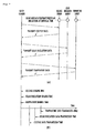
- Figs. 5a and 5b illustrate that a sensing unit detects at least any one of a state of a photovoltaic device and environmental information around the photovoltaic device, and transmits, to a data logger, state information representing at least any one of the state of the photovoltaic device and environmental information around the photovoltaic device according to another embodiment.
- Fig. 5a illustrates information transmission between the sensing unit 319 and the data logger 330.
- Fig. 5b illustrates that each sensor of the sensing unit 319 sequentially sense at least any one of the state of the photovoltaic device 300 and environmental information around the photovoltaic device 300.
- the sensing unit 319 includes a voltage sensor, solar insolation sensor, and temperature sensor.
- the plurality of sensors sequentially sense at least any one of the state of the photovoltaic device 300 and environmental information around the photovoltaic device 300 and sequentially transmit state information representing the sensed information, there exist time differences between state informations representing different states.
- the state information in performance analysis and analysis of causes of failures of the photovoltaic device 300.
- MPPT maximum power point tracking
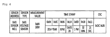
- Fig. 6 shows a syntax of state information for a photovoltaic device according to another embodiment.
- the state information representing at least any one of the state of the photovoltaic device 300 and the environmental information around the photovoltaic device 300 may include at least any one of identification information for identifying a sensor, measurement information for representing a value sensed by the sensor, time information for representing a sensing time, and error detection information for detecting an information error.
- the identification information for identifying a sensor may include at least any one of sensor address information for representing a connection position of the sensor and sensor type information for representing a sensor type.
- the error detection information may be cyclic redundancy check (CRC) information.
- CRC cyclic redundancy check
- a state information packet of the sensing unit 319 includes a field for representing the sensor address information, a field for representing the sensor type information, a field for representing the measurement information, a field for representing the time information, and a field for representing the error detection information.
- the management server 350 may precisely and efficiently manage the photovoltaic device 300 on the basis of the time information included in the state information.
- the sensing unit 319 may insert, into the state information, at least any one of the identification information for identifying the sensor, the measurement information for representing a value sensed by the sensor, the time information for representing the sensing time, and the error detection information for detecting the information error, and may transmit the state information to the data logger 330.
- the sensing unit 319 may transmit the state information without inserting the time information and the data logger 330 may insert the time information to the state information transmitted by the sensing unit 319. Furthermore, in a detailed embodiment, the sensing unit 319 may transmit only the measurement information and the data logger 330 may insert informations other than the measurement information included in the state information. In detail, the sensing unit 319 may transmit the state information including only the measurement information, and the data logger 330 may insert, into the state information, at least any one of the time information for representing the sensing time and the error detection information for detecting the information error to transmit the state information to the management server 450. In this case, a configuration of the sensing unit 319 may be simplified because the sensing unit 319 senses at least any one of the state of the photovoltaic device 300 and the environmental information around the photovoltaic device 300, and simply transmits the sensed result.
- Figs. 7a and 7b illustrate that a sensing unit detects at least any one of a state of a photovoltaic device and environmental information around the photovoltaic device, and transmits, to a data logger, state information representing at least any one of the state of the photovoltaic device and environmental information around the photovoltaic device according to another embodiment.
- Fig. 7a illustrates information transmission between the sensing unit 319 and the data logger 330.
- Fig. 7b illustrates that the sensors of the sensing unit 319 simultaneously sense at least any one of the state of the photovoltaic device 300 and environmental information around the photovoltaic device 300.
- the sensing unit 319 includes the voltage sensor, solar insolation sensor, and temperature sensor. As illustrated in Figs. 7a and 7b , when the plurality of sensors included in the sensing unit 319 simultaneously sense at least any one of the state of the photovoltaic device 300 and the environmental information around the photovoltaic device 300, the state information may be obtained more consistently than the case of being sequentially sensed.
- the sensing unit 319 may sequentially transmit it to the data logger 330.
- FIG. 8 is an operation flowchart of a sensing unit of a photovoltaic device according to another embodiment.
- the sensing unit 319 senses at least any one of the state of the photovoltaic device 300 and the surrounding environment state of the photovoltaic device 300 (operation S501). As described above, the sensing unit 319 may sense at least any one of a voltage of the power generated by the photovoltaic device 300, a solar insolation and temperature of a place where the photovoltaic device 300 is located, and a temperature in the photovoltaic device 300.
- the sensing unit 319 obtains time information for representing a time when at least any one of the state of the photovoltaic device 300 and the surrounding environment state of the photovoltaic device 300 is sensed (operation S503).
- the sensing unit 319 transmits state information representing the time information and at least any one of the state of the photovoltaic device 300 and the surrounding environment state of the photovoltaic device 300 (operation S505).
- the sensing unit 319 may transmit, to the data logger 330, the state information representing at least any one of the state of the photovoltaic device 300 and the surrounding environment state of the photovoltaic device 300.
- the state information may have the same format as that explained in relation to Fig. 6 .
- the sensing unit 319 may sense the at least any one of the state of the photovoltaic device 300 and the surrounding environment state of the photovoltaic device 300, and may transmit state information including only the sensed information.
- the data logger 330 may insert time information into the state information and then transmit the state information to the management server 450.
- the photovoltaic device 300 may be efficiently managed by obtaining the state of the photovoltaic device 300 and precise information on the surrounding environment thereof.
- a photovoltaic device can be efficiently and precisely managed by providing the photovoltaic device for efficiently and accurately recording and transmitting a state thereof.
- the embodiments allow the time when the state of the photovoltaic device is recorded to be known by recording a state of the photovoltaic device and a time when the state of the photovoltaic device is detected and transmitting them together.
- a plurality of sensing units record the state of the photovoltaic device at the same time and allow that a plurality of states of the photovoltaic device are precisely analyzed.
Landscapes
- Engineering & Computer Science (AREA)
- Power Engineering (AREA)
- Physics & Mathematics (AREA)
- General Physics & Mathematics (AREA)
- Photovoltaic Devices (AREA)
- Supply And Distribution Of Alternating Current (AREA)
- Photometry And Measurement Of Optical Pulse Characteristics (AREA)
- Remote Monitoring And Control Of Power-Distribution Networks (AREA)
- Air Conditioning Control Device (AREA)
Abstract
Description
- The present disclosure relates to a photovoltaic device.
- Interest in alternative energy is picking up because of depletion of fossil energy such as petroleum and concern about environmental pollution. Among them, photovoltaic power generation is being spotlighted which generates electricity on a mass scale by deploying a panel in a large scale with a photovoltaic cell attached thereon to use solar voltaic energy. Since the photovoltaic power generation uses solar voltaic energy that is unlimited and pollution-free, there is no occurrence of air pollution or wastes.
- There are two photovoltaic power generation types of an off-grid type and on-grid type. In the off-grid type, a photovoltaic device is connected to a stand-alone load that is not connected to a grid. In the on-grid type, a photovoltaic device is connected to an existing grid. The photovoltaic device transmits electricity, which is generated in the daytime, to the grid and receives electricity from the grid at night or in case of rain. In order to efficiently use the on-grid type photovoltaic system, a photovoltaic system is introduced for storing idle power in a Battery Energy Storage System (BESS) in case of a light load, and for supplying power discharged from the BESS in addition to power from the photovoltaic device to the grid in case of overload.
- Power generation output of this photovoltaic device is influenced by environmental factors such as weather or time. Accordingly, it is necessary to continuously detect these environmental elements. In addition, the photovoltaic device requires a relatively wide area for absorbing a large amount of solar light. Accordingly, there are many cases where the photovoltaic device is located remotely from a general residence area or a working area of a manager who manages the photovoltaic device. Due to this reason, the photovoltaic device includes a data logger for collecting a state of the photovoltaic device and transmit it to the outside thereof.
- Embodiments provide a photovoltaic device for efficiently and accurately recording and transmitting a state of the photovoltaic device.
- Embodiments also provide a photovoltaic device for recording and transmitting together a state of the photovoltaic device and a time when the state of the photovoltaic device is detected. At this point, a plurality of sensing units may record the state of the photovoltaic device at the same time.
- In one embodiment, a photovoltaic device includes: a photovoltaic cell array absorbing solar voltaic energy to convert the solar voltaic energy to electrical energy; and a sensing unit sensing at least any one of power generation information for representing a state of the photovoltaic device and environmental information for representing environmental information around the photovoltaic device, and measuring a time when the at least one of the power generation information and the environmental information is sensed.
- The sensing unit may include a plurality of sensors, wherein the plurality of sensors sense the at least any one of the power generation information and the environmental information at an identical time.
- The sensing unit may transmit state information including the at least any one of the power generation information and the environmental information, and the time when the at least any one of the power generation information and the environmental information is sensed.
- The sensing unit may include a plurality of sensors, wherein the plurality of sensors sequentially transmit the state information.
- The state information may include at least any one of identification information for identifying a sensor included in the sensing unit, measurement information for representing a value sensed by the sensor, time information for representing a time when the sensor senses, and error detecting information for detecting an information error.
- The identification information may include at least any one of sensor address information for representing a connection position of the sensor, and sensor type information for representing a type of the sensor.
- The power generation information may include at least any one of a voltage of power generated by the photovoltaic device and a temperature in the photovoltaic device, and the state information may include at least any one of a solar insolation and temperature of a place where the photovoltaic device is located.
- In another embodiment, an operation method of a photovoltaic device, includes: absorbing solar voltaic energy to convert the solar voltaic energy to electrical energy; sensing at least any one of power generation information for representing a state of the photovoltaic device and environmental information for representing environmental information around the photovoltaic device; and measuring a time when the at least one of the power generation information and the environmental information is sensed.
- The details of one or more embodiments are set forth in the accompanying drawings and the description below. Other features will be apparent from the description and drawings, and from the claims.
-
-
Fig. 1 is a block diagram of a photovoltaic device according to an embodiment. -
Fig. 2 is an operation flowchart of a photovoltaic device according to an embodiment. -
Fig. 3 is a block diagram of a data logger connected to a photovoltaic device according to another embodiment. -
Fig. 4 is an operation flowchart of a photovoltaic device according to another embodiment. -
Figs. 5a and 5b illustrate that a sensing unit detects at least any one of a state of a photovoltaic device and environmental information around the photovoltaic device, and transmits, to a data logger, state information representing at least any one of the state of the photovoltaic device and environmental information around the photovoltaic device according to another embodiment. -
Fig. 6 shows a syntax of state information for a photovoltaic device according to another embodiment. -
Figs. 7a and 7b illustrate that a sensing unit detects at least any one of a state of a photovoltaic device and environmental information around the photovoltaic device, and transmits, to a data logger, state information representing at least any one of the state of the photovoltaic device and environmental information around the photovoltaic device according to another embodiment. -
Fig. 8 is an operation flowchart of a sensing unit of a photovoltaic device according to another embodiment. - Reference will now be made in detail to the embodiments of the present disclosure, examples of which are illustrated in the accompanying drawings.
- A photovoltaic device according to an embodiment will be described in detail with reference to the accompanying drawings. The invention may, however, be embodied in many different forms and should not be construed as being limited to the embodiments set forth herein; rather, that alternate embodiments included in other retrogressive inventions or falling within the spirit and scope of the present disclosure can easily be derived through adding, altering, and changing, and will fully convey the concept of the invention to those skilled in the art.
- Hereinafter, embodiments of the present invention will be described in detail with reference to the accompanying drawings so that the present invention can be easily realized by those skilled in the art. The present invention can be practiced in various ways and is not limited to the embodiments described herein. In the drawings, parts which are not related to the description are omitted to clearly set forth the present invention and similar elements are denoted by similar reference symbols throughout the specification.
- In addition, when an element is referred to as "comprising" or "including" a component, it does not preclude another component but may further include the other component unless the context clearly indicates otherwise.
-
FIG. 1 is a block diagram of a photovoltaic device according to an embodiment. - A photovoltaic device 300 according to an embodiment includes a
photovoltaic array 301, aninverter 303, anAC filter 305, an AC/AC converter 307, agrid 309, a chargingcontroller 311, a Battery Energy Storage System (BESS) 313, asystem controller 315, aload 317, asensing unit 319, and adata logger 330. - Accordingly, the
photovoltaic cell array 301 absorbs the solar voltaic energy to convert it to the electrical energy. - The
inverter 303 inverts DC power to AC power. Theinverter 303 receives, through the chargingcontroller 311, the DC power supplied by thephotovoltaic cell array 301 or the DC power discharged from theBESS 113 to invert it to the AC power. - The
AC filter 305 filters noise from the inverted AC power. - The AC/
AC converter 307 performs conversion on the magnitude of the AC power that the noise is filtered and supplies the magnitude-converted AC power to thegrid 309 andload 317. - The
grid 309 is a system in which a power plant, a substation, a transmission/distribution line, and a load are integrated to generate and use power. - The charging
controller 311 controls charge of and discharge from theBESS 313. - The
BESS 313 receives electrical energy from thephotovoltaic cell array 301 to be charged therewith and discharges the electrical energy according to a power supply-demand situation of thegrid 309 orload 317. - The
system controller 315 controls operations of the chargingcontroller 311,inverter 303,AC filter 305, and AC/AC converter 307. - The
load 317 receives to consume the electrical energy. - The
sensing unit 319 senses at least any one of a state of the photovoltaic device 300 and a surrounding environment state around the photovoltaic device 300. In detail, thesensing unit 319 may detect the state of the photovoltaic device 300. At this point, the state of the photovoltaic device 300 may include at least any one of a voltage of power generated by the photovoltaic device 300 and a temperature in the photovoltaic device 300. In addition, thesensing unit 319 may detect the state of surrounding environment around the photovoltaic device 300. At this point, the state of the photovoltaic device 300 may include at least any one of a solar insolation and temperature of a place where the photovoltaic device 300 is located. Accordingly, thesensing unit 319 may include a plurality of sensors. In detail, thesensing unit 319 may include at least any one of a solar insolation sensor, temperature sensor, and voltage sensor. - The
data logger 330 receives the state information from thesensing unit 319 to transmit it to anexternal management server 350. - The manager of the photovoltaic device 300 may check whether the photovoltaic device 300 is abnormal and a power generation state through the state information that is transmitted to the managing
server 350. In detail, the manager of the photovoltaic device 300 may check whether a failure occurs in the photovoltaic device 300 when the power generation is smaller compared to the solar insolation. Accordingly, the manager of the photovoltaic device 300 may inspect the photovoltaic device 300. In another detailed embodiment, when quality of power generated by the photovoltaic device 300 is not good, the manager of the photovoltaic device 300 may estimate a replacement period of an element that is necessary to the photovoltaic device 300. In another detailed embodiment, when a temperature of the photovoltaic device 300 is excessively high or a surrounding temperature of the photovoltaic device is excessively high, the manager may stop operation of the photovoltaic device 300 for a certain period. In another detailed embodiment, when an owner of the photovoltaic device 300 earns an income for supplying power to thegrid 309, the information transmitted by thedata logger 330 may be a basis material for the income. In detail, when a less income is calculated than that of other days due to a small amount of supplying power, the owner of the photovoltaic device 300 may check a cause of the small amount of power generation by using information on a small solar insolation transmitted from thedata logger 330. Like this, thesensing unit 319 anddata logger 330 allow the photovoltaic device 300 to be efficiently managed and maintained. -
Fig. 2 is an operation flowchart of a photovoltaic device according to an embodiment. - The
photovoltaic cell array 301 converts the solar voltaic energy to the electrical energy (operation S101). - The
system controller 315 determines whether it is necessary to supply power to the grid 309 (operation S103). Whether it is necessary to supply power to thegrid 309 may be determined on the basis of whether thegrid 309 is overloaded or light-loaded. - When it is not necessary to supply power to the
grid 309, thesystem controller 315 controls the chargingcontroller 311 to charge the BESS 313 (operation S105). In detail, thesystem controller 315 may generate a control signal for controlling the chargingcontroller 311. The chargingcontroller 311 may receive the control signal and charge theBESS 313. - The
system controller 315 determines whether it is necessary to discharge the BESS 313 (operation S107). Thesystem controller 115 may determine whether it is necessary to discharge the BESS, since power demand of thegrid 309 is not satisfied only with electrical energy supplied by thephotovoltaic cell array 301. In addition, thesystem controller 315 may determine whether theBESS 313 stores enough energy to discharge. - When it is necessary to discharge the
BESS 313, thesystem controller 315 controls the chargingcontroller 311 to discharge theBESS 313. In detail, thesystem controller 315 may generate a control signal for controlling the chargingcontroller 311. The chargingcontroller 311 may receive the control signal and discharge theBESS 313. - The
inverter 303 inverts, to AC power, the electrical energy discharged from theBESS 313 and the electrical energy converted by the photovoltaic cell array 301 (operation S111). At this point, the on-grid photovoltaic device 300 inverts, with oneinverter 303, the electrical energy discharged from theBESS 313 and the electrical energy converted by thephotovoltaic cell array 301. Each electrical device has an available power limit. This limit is divided into an instant limit and a long time use limit, and regulatory power is determined as maximum power that does not damage a device and is available for a long time. In order to maximize efficiency of theinverter 303, theBESS 313 and thephotovoltaic cell array 301 are required to supply power so that theinverter 303 uses power of about 40 % to about 60 % of such a regulatory power. - The
AC filter 305 filters noise from the inverted AC power (operation S113). - The AC/
AC converter 307 performs conversion on the magnitude of voltage of the filtered AC power to supply power to thegrid 309 or load 317 (operation S115). - The photovoltaic device 300 supplies the converted power to the
grid 309 or load 317 (operation S117). - An operation of the
data logger 330 will be described in detail with reference toFigs. 3 and 4 . -
FIG. 3 is a block diagram of a data logger connected to a photovoltaic device according to another embodiment. - The
data logger 330 includes acontroller 331, acommunication unit 333, and amemory 335. - The
controller 331 controls an operation of thedata logger 330. - The
communication unit 333 receives, from thesensing unit 319, state information representing at least any one of a state of the photovoltaic device 300 and a surrounding environment state of the photovoltaic device 300. In addition, thecommunication unit 333 transmits the state information on the photovoltaic device 300 to themanagement server 350. - The
memory 335 stores information necessary for operation of thedata logger 330. -
FIG. 4 is an operation flowchart of a photovoltaic device according to another embodiment. - The
sensing unit 319 senses at least any one of a state of the photovoltaic device 300 and a surrounding environment state of the photovoltaic device 300 (operation S301). As described above, thesensing unit 319 may sense at least any one of a voltage of power generated by the photovoltaic device 300, solar insolation on and a temperature of a place where the photovoltaic device 300 is located, and a temperature in the photovoltaic device 300. - The
sensing unit 319 transmits state information representing at least any one of a state of the photovoltaic device 300 and a surrounding environment state of the photovoltaic device 300 (operation S303). In detail, thesensing unit 319 may transmit, to thedata logger 330, the state information representing at least any one of a state of the photovoltaic device 300 and a surrounding environment state of the photovoltaic device 300. -
Figs. 5a and 5b illustrate that a sensing unit detects at least any one of a state of a photovoltaic device and environmental information around the photovoltaic device, and transmits, to a data logger, state information representing at least any one of the state of the photovoltaic device and environmental information around the photovoltaic device according to another embodiment. -
Fig. 5a illustrates information transmission between thesensing unit 319 and thedata logger 330.Fig. 5b illustrates that each sensor of thesensing unit 319 sequentially sense at least any one of the state of the photovoltaic device 300 and environmental information around the photovoltaic device 300. In embodiments illustrated inFigs. 5a and 5b , thesensing unit 319 includes a voltage sensor, solar insolation sensor, and temperature sensor. As illustrated inFig. 5 , when the plurality of sensors sequentially sense at least any one of the state of the photovoltaic device 300 and environmental information around the photovoltaic device 300 and sequentially transmit state information representing the sensed information, there exist time differences between state informations representing different states. Accordingly, it is difficult to use the state information in performance analysis and analysis of causes of failures of the photovoltaic device 300. For example, it is difficult to use the state information in a maximum power point tracking (MPPT) algorithm for analyzing a function of a solar light inverter. - In addition, it is also difficult to determine the state information by considering a time when the
data logger 330 or themanagement server 350 is sensed, since information transmitted by thesensing unit 319 does not include the time when the state information is sensed. An operation of thesensing unit 319 or thedata logger 330 for addressing these limitations will be described with reference toFigs. 6 to 8 . -
Fig. 6 shows a syntax of state information for a photovoltaic device according to another embodiment. - The state information representing at least any one of the state of the photovoltaic device 300 and the environmental information around the photovoltaic device 300 may include at least any one of identification information for identifying a sensor, measurement information for representing a value sensed by the sensor, time information for representing a sensing time, and error detection information for detecting an information error. In detail, the identification information for identifying a sensor may include at least any one of sensor address information for representing a connection position of the sensor and sensor type information for representing a sensor type. In addition, in a detailed embodiment, the error detection information may be cyclic redundancy check (CRC) information. In the embodiment illustrated in
Fig. 6 , a state information packet of thesensing unit 319 includes a field for representing the sensor address information, a field for representing the sensor type information, a field for representing the measurement information, a field for representing the time information, and a field for representing the error detection information. When the state information includes the time information for representing the time when the sensor senses, themanagement server 350 may precisely and efficiently manage the photovoltaic device 300 on the basis of the time information included in the state information. - In a detailed embodiment, the
sensing unit 319 may insert, into the state information, at least any one of the identification information for identifying the sensor, the measurement information for representing a value sensed by the sensor, the time information for representing the sensing time, and the error detection information for detecting the information error, and may transmit the state information to thedata logger 330. - In a detailed embodiment, when sensing information and immediately transmitting the information, the
sensing unit 319 may transmit the state information without inserting the time information and thedata logger 330 may insert the time information to the state information transmitted by thesensing unit 319. Furthermore, in a detailed embodiment, thesensing unit 319 may transmit only the measurement information and thedata logger 330 may insert informations other than the measurement information included in the state information. In detail, thesensing unit 319 may transmit the state information including only the measurement information, and thedata logger 330 may insert, into the state information, at least any one of the time information for representing the sensing time and the error detection information for detecting the information error to transmit the state information to the management server 450. In this case, a configuration of thesensing unit 319 may be simplified because thesensing unit 319 senses at least any one of the state of the photovoltaic device 300 and the environmental information around the photovoltaic device 300, and simply transmits the sensed result. -
Figs. 7a and 7b illustrate that a sensing unit detects at least any one of a state of a photovoltaic device and environmental information around the photovoltaic device, and transmits, to a data logger, state information representing at least any one of the state of the photovoltaic device and environmental information around the photovoltaic device according to another embodiment. -
Fig. 7a illustrates information transmission between thesensing unit 319 and thedata logger 330.Fig. 7b illustrates that the sensors of thesensing unit 319 simultaneously sense at least any one of the state of the photovoltaic device 300 and environmental information around the photovoltaic device 300. In embodiments ofFigs. 7a and 7b , thesensing unit 319 includes the voltage sensor, solar insolation sensor, and temperature sensor. As illustrated inFigs. 7a and 7b , when the plurality of sensors included in thesensing unit 319 simultaneously sense at least any one of the state of the photovoltaic device 300 and the environmental information around the photovoltaic device 300, the state information may be obtained more consistently than the case of being sequentially sensed. In addition, when being unable to simultaneously transmit, to thedata logger 330, the at least any one of the sensed state of the photovoltaic device 300 or the sensed environmental information around the photovoltaic device 300 due to a communication traffic control or the like, thesensing unit 319 may sequentially transmit it to thedata logger 330. -
FIG. 8 is an operation flowchart of a sensing unit of a photovoltaic device according to another embodiment. - The
sensing unit 319 senses at least any one of the state of the photovoltaic device 300 and the surrounding environment state of the photovoltaic device 300 (operation S501). As described above, thesensing unit 319 may sense at least any one of a voltage of the power generated by the photovoltaic device 300, a solar insolation and temperature of a place where the photovoltaic device 300 is located, and a temperature in the photovoltaic device 300. - The
sensing unit 319 obtains time information for representing a time when at least any one of the state of the photovoltaic device 300 and the surrounding environment state of the photovoltaic device 300 is sensed (operation S503). - The
sensing unit 319 transmits state information representing the time information and at least any one of the state of the photovoltaic device 300 and the surrounding environment state of the photovoltaic device 300 (operation S505). In detail, thesensing unit 319 may transmit, to thedata logger 330, the state information representing at least any one of the state of the photovoltaic device 300 and the surrounding environment state of the photovoltaic device 300. At this point, the state information may have the same format as that explained in relation toFig. 6 . In addition, as described above, thesensing unit 319 may sense the at least any one of the state of the photovoltaic device 300 and the surrounding environment state of the photovoltaic device 300, and may transmit state information including only the sensed information. Thedata logger 330 may insert time information into the state information and then transmit the state information to the management server 450. - Through this operation, the photovoltaic device 300 may be efficiently managed by obtaining the state of the photovoltaic device 300 and precise information on the surrounding environment thereof.
- According to embodiments, a photovoltaic device can be efficiently and precisely managed by providing the photovoltaic device for efficiently and accurately recording and transmitting a state thereof. In particular, the embodiments allow the time when the state of the photovoltaic device is recorded to be known by recording a state of the photovoltaic device and a time when the state of the photovoltaic device is detected and transmitting them together. In addition, a plurality of sensing units record the state of the photovoltaic device at the same time and allow that a plurality of states of the photovoltaic device are precisely analyzed.
- In the foregoing, features, structures, or effects described in connection with embodiments are included in at least one embodiment, and are not necessarily limited to one embodiment. Furthermore, the exemplified features, structures, or effects in various embodiments can be combined and modified by those skilled in the art. Accordingly, contents in connection with these combination and modification should be construed to fall in the scope of the present invention.
- Although embodiments have been described with reference to a number of illustrative embodiments thereof, it should be understood that numerous other modifications and embodiments can be devised by those skilled in the art that will fall within the spirit and scope of the principles of this disclosure. More particularly, various variations and modifications are possible in the component parts and/or arrangements of the subject combination arrangement within the scope of the disclosure, the drawings and the appended claims. In addition to variations and modifications in the component parts and/or arrangements, alternative uses will also be apparent to those skilled in the art.
Claims (14)
- A photovoltaic device (300) comprising:a photovoltaic cell array (301) absorbing solar voltaic energy to convert the solar voltaic energy to electrical energy; anda sensing unit (319) sensing at least any one of power generation information for representing a state of the photovoltaic device (300) and environmental information for representing environmental information around the photovoltaic device (300), and measuring a time when the at least one of the power generation information and the environmental information is sensed.
- The photovoltaic device (300) according to claim 1, wherein the sensing unit (319) comprises a plurality of sensors,
wherein the plurality of sensors sense the at least any one of the power generation information and the environmental information at an identical time. - The photovoltaic device (300) according to claim 1, wherein the sensing unit (319) transmits state information comprising the at least any one of the power generation information and the environmental information, and the time when the at least any one of the power generation information and the environmental information is sensed.
- The photovoltaic device (300) according to claim 3, wherein the sensing unit (319) comprises a plurality of sensors,
wherein the plurality of sensors sequentially transmit the state information. - The photovoltaic device (300) according to claim 3, wherein the state information comprises at least any one of identification information for identifying a sensor comprised in the sensing unit (319), measurement information for representing a value sensed by the sensor, time information for representing a time when the sensor senses, and error detecting information for detecting an information error.
- The photovoltaic device (300) according to claim 5, wherein the identification information comprises at least any one of sensor address information for representing a connection position of the sensor, and sensor type information for representing a type of the sensor.
- The photovoltaic device (300) according to claim 1, wherein the power generation information comprises at least any one of a voltage of power generated by the photovoltaic device (300) and a temperature in the photovoltaic device (300), and
the state information comprises at least any one of a solar insolation and temperature of a place where the photovoltaic device (300) is located. - An operation method of a photovoltaic device (300), the operation method comprising:absorbing solar voltaic energy to convert the solar voltaic energy to electrical energy;sensing at least any one of power generation information for representing a state of the photovoltaic device (300) and environmental information for representing environmental information around the photovoltaic device; andmeasuring a time when the at least one of the power generation information and the environmental information is sensed.
- The operation method according to claim 8, wherein the sensing of the at least any one of power generation information and the environmental information comprises sensing, by a plurality of sensors, at least any one of the power generation information and the environmental information at an identical time.
- The operation method according to claim 8, further comprising:transmitting state information comprising the at least any one of the power generation information and the environmental information, and the time when the at least any one of the power generation information and the environmental information is sensed.
- The operation method according to claim 10, wherein the transmitting of the state information comprises sequentially transmitting, by a plurality of sensors, the state information.
- The operation method according to claim 10, wherein the state information comprises at least any one of identification information for identifying a sensor comprised in the sensing unit, measurement information for representing a value sensed by the sensor, time information for representing a time when the sensor senses, and error detecting information for detecting an error in information.
- The operation method according to claim 12, wherein the identification information comprises at least any one of sensor address information for representing a connection position of the sensor, and sensor type information for representing a type of the sensor.
- The operation method according to claim 8, wherein the power generation information comprises at least any one of a voltage of power generated by the photovoltaic device and a temperature in the photovoltaic device (300), and
the state information comprises at least any one of a solar insolation and temperature of a place where the photovoltaic device (300) is located.
Applications Claiming Priority (1)
| Application Number | Priority Date | Filing Date | Title |
|---|---|---|---|
| KR1020150008919A KR101962329B1 (en) | 2015-01-19 | 2015-01-19 | Photovoltaic device |
Publications (2)
| Publication Number | Publication Date |
|---|---|
| EP3046202A1 true EP3046202A1 (en) | 2016-07-20 |
| EP3046202B1 EP3046202B1 (en) | 2020-03-18 |
Family
ID=54544952
Family Applications (1)
| Application Number | Title | Priority Date | Filing Date |
|---|---|---|---|
| EP15194414.7A Active EP3046202B1 (en) | 2015-01-19 | 2015-11-13 | Photovoltaic device |
Country Status (6)
| Country | Link |
|---|---|
| US (1) | US9882388B2 (en) |
| EP (1) | EP3046202B1 (en) |
| JP (1) | JP2016135094A (en) |
| KR (1) | KR101962329B1 (en) |
| CN (1) | CN105811879B (en) |
| ES (1) | ES2795007T3 (en) |
Families Citing this family (2)
| Publication number | Priority date | Publication date | Assignee | Title |
|---|---|---|---|---|
| CN109104152A (en) * | 2018-08-28 | 2018-12-28 | 韩劲草 | Auto cleaning system and clean method for photovoltaic plant |
| US20220328703A1 (en) * | 2021-04-12 | 2022-10-13 | OptoGlo, Inc. | Printable solar sign |
Citations (5)
| Publication number | Priority date | Publication date | Assignee | Title |
|---|---|---|---|---|
| US20050051209A1 (en) * | 2003-09-04 | 2005-03-10 | Konkuk University | System and method for implementing virtual solar cell |
| US20080147335A1 (en) * | 2006-12-06 | 2008-06-19 | Meir Adest | Monitoring of distributed power harvesting systems using dc power sources |
| US20110282600A1 (en) * | 2010-05-12 | 2011-11-17 | General Electric Company | System and method for photovoltaic plant power curve measurement and health monitoring |
| US20120242320A1 (en) * | 2011-03-22 | 2012-09-27 | Fischer Kevin C | Automatic Generation And Analysis Of Solar Cell IV Curves |
| EP2600406A2 (en) * | 2011-11-29 | 2013-06-05 | LSIS Co., Ltd. | Solar device |
Family Cites Families (11)
| Publication number | Priority date | Publication date | Assignee | Title |
|---|---|---|---|---|
| CN101640434A (en) | 2008-08-01 | 2010-02-03 | 新奥科技发展有限公司 | Photovoltaic parallel grid charging system for electric car |
| US20110139184A1 (en) * | 2009-12-16 | 2011-06-16 | Nagendra Srinivas Cherukupalli | Systems, Circuits, and Methods for an Intelligent Cleaning System for an Adaptive Solar Power System |
| US8502129B2 (en) * | 2010-02-16 | 2013-08-06 | Western Gas And Electric, Inc. | Integrated remotely controlled photovoltaic system |
| JP2011181853A (en) * | 2010-03-03 | 2011-09-15 | Mitsubishi Electric Corp | Solar photovoltaic power generation system, maintenance terminal, and data collection device |
| JP5558375B2 (en) * | 2011-01-20 | 2014-07-23 | 三菱電機株式会社 | Data update device, data update system, data update program, and data update method |
| US20120310427A1 (en) * | 2011-05-31 | 2012-12-06 | Williams B Jeffery | Automatic Monitoring and Adjustment of a Solar Panel Array |
| JP2013038345A (en) | 2011-08-10 | 2013-02-21 | Toshiba Corp | Photovoltaic power generation system |
| CN202260633U (en) | 2011-10-10 | 2012-05-30 | 保定天威集团有限公司 | Photovoltaic power station monitoring system |
| WO2014031145A1 (en) * | 2012-08-22 | 2014-02-27 | LT Lighting (Taiwan) Corp. | New electric energy deployment model for solar system |
| KR20140127930A (en) | 2013-03-28 | 2014-11-05 | (주) 디지털파워 | Solar photovoltaic power generation system |
| KR101817340B1 (en) * | 2014-01-20 | 2018-01-10 | 한국전자통신연구원 | Apparatus and method for collecting state information of solar module |
-
2015
- 2015-01-19 KR KR1020150008919A patent/KR101962329B1/en not_active Expired - Fee Related
- 2015-11-02 US US14/930,517 patent/US9882388B2/en not_active Expired - Fee Related
- 2015-11-13 EP EP15194414.7A patent/EP3046202B1/en active Active
- 2015-11-13 ES ES15194414T patent/ES2795007T3/en active Active
- 2015-11-17 JP JP2015224602A patent/JP2016135094A/en active Pending
-
2016
- 2016-01-07 CN CN201610009425.8A patent/CN105811879B/en not_active Expired - Fee Related
Patent Citations (5)
| Publication number | Priority date | Publication date | Assignee | Title |
|---|---|---|---|---|
| US20050051209A1 (en) * | 2003-09-04 | 2005-03-10 | Konkuk University | System and method for implementing virtual solar cell |
| US20080147335A1 (en) * | 2006-12-06 | 2008-06-19 | Meir Adest | Monitoring of distributed power harvesting systems using dc power sources |
| US20110282600A1 (en) * | 2010-05-12 | 2011-11-17 | General Electric Company | System and method for photovoltaic plant power curve measurement and health monitoring |
| US20120242320A1 (en) * | 2011-03-22 | 2012-09-27 | Fischer Kevin C | Automatic Generation And Analysis Of Solar Cell IV Curves |
| EP2600406A2 (en) * | 2011-11-29 | 2013-06-05 | LSIS Co., Ltd. | Solar device |
Also Published As
| Publication number | Publication date |
|---|---|
| US9882388B2 (en) | 2018-01-30 |
| KR20160089228A (en) | 2016-07-27 |
| CN105811879B (en) | 2018-09-04 |
| ES2795007T3 (en) | 2020-11-20 |
| EP3046202B1 (en) | 2020-03-18 |
| CN105811879A (en) | 2016-07-27 |
| JP2016135094A (en) | 2016-07-25 |
| US20160211671A1 (en) | 2016-07-21 |
| KR101962329B1 (en) | 2019-03-26 |
Similar Documents
| Publication | Publication Date | Title |
|---|---|---|
| CN101636847B (en) | Monitoring system of distributed power harvesting systems using DC power sources | |
| KR101066064B1 (en) | Remote monitoring device and method of solar module | |
| KR200457335Y1 (en) | Smart solar power system | |
| US20100201493A1 (en) | Photoelectric cell device and malfunction determining method | |
| KR101674019B1 (en) | Solar power equipment monitoring device server | |
| KR101023445B1 (en) | Solar cell module remote monitoring and control system | |
| US20120249152A1 (en) | Charging/discharging determination apparatus and computer-readable non-transitory medium storing charging/discharging determination program | |
| KR20170007625A (en) | Micro-grid solar energy havesting based energy integrated management system for energy efficiency | |
| CN105811577B (en) | Data acquisition device for photovoltaic devices | |
| JP6437473B2 (en) | Solar power system | |
| US9882388B2 (en) | Photovoltaic device | |
| KR101424165B1 (en) | System for monitoring a solar photovoltaic power generation having a idealized monitoring network circumstance | |
| KR102281897B1 (en) | DAQ and Independent solar remote control system through clustering-based power measurement using DAQ | |
| KR20200017747A (en) | Solar Energy Storage System | |
| CN116802377A (en) | blind device | |
| KR20200017585A (en) | Sunlight generation ess management system for house | |
| KR20220131082A (en) | Distributed energy storage system of photovoltaic power generation and photovoltaic power generation system using the same | |
| US20190067948A1 (en) | System and method for integrally managing electric energy | |
| KR101395642B1 (en) | System for monitoring a solar photovoltaic power generation able to caculate a degree of pollution of solar photovoltaic power generation | |
| KR101957188B1 (en) | Data collecting device for photovoltaic device | |
| KR101957195B1 (en) | A monitoring apparatus for photovoltaic device | |
| KR102200296B1 (en) | Photovoltaic device | |
| KR20120131706A (en) | Smart solar power system | |
| Mahamud et al. | IoT Based Wireless Battery Monitoring System for Enhanced Solar Micro-Grid Performance in Bangladesh | |
| CN204681315U (en) | A kind of data acquisition unit of solar panel |
Legal Events
| Date | Code | Title | Description |
|---|---|---|---|
| PUAI | Public reference made under article 153(3) epc to a published international application that has entered the european phase |
Free format text: ORIGINAL CODE: 0009012 |
|
| AK | Designated contracting states |
Kind code of ref document: A1 Designated state(s): AL AT BE BG CH CY CZ DE DK EE ES FI FR GB GR HR HU IE IS IT LI LT LU LV MC MK MT NL NO PL PT RO RS SE SI SK SM TR |
|
| AX | Request for extension of the european patent |
Extension state: BA ME |
|
| STAA | Information on the status of an ep patent application or granted ep patent |
Free format text: STATUS: REQUEST FOR EXAMINATION WAS MADE |
|
| 17P | Request for examination filed |
Effective date: 20170104 |
|
| RBV | Designated contracting states (corrected) |
Designated state(s): AL AT BE BG CH CY CZ DE DK EE ES FI FR GB GR HR HU IE IS IT LI LT LU LV MC MK MT NL NO PL PT RO RS SE SI SK SM TR |
|
| STAA | Information on the status of an ep patent application or granted ep patent |
Free format text: STATUS: EXAMINATION IS IN PROGRESS |
|
| 17Q | First examination report despatched |
Effective date: 20190807 |
|
| GRAP | Despatch of communication of intention to grant a patent |
Free format text: ORIGINAL CODE: EPIDOSNIGR1 |
|
| STAA | Information on the status of an ep patent application or granted ep patent |
Free format text: STATUS: GRANT OF PATENT IS INTENDED |
|
| INTG | Intention to grant announced |
Effective date: 20191107 |
|
| RAP1 | Party data changed (applicant data changed or rights of an application transferred) |
Owner name: LSIS CO., LTD. |
|
| RIN1 | Information on inventor provided before grant (corrected) |
Inventor name: CHO, CHOONG KUN |
|
| GRAS | Grant fee paid |
Free format text: ORIGINAL CODE: EPIDOSNIGR3 |
|
| GRAA | (expected) grant |
Free format text: ORIGINAL CODE: 0009210 |
|
| STAA | Information on the status of an ep patent application or granted ep patent |
Free format text: STATUS: THE PATENT HAS BEEN GRANTED |
|
| AK | Designated contracting states |
Kind code of ref document: B1 Designated state(s): AL AT BE BG CH CY CZ DE DK EE ES FI FR GB GR HR HU IE IS IT LI LT LU LV MC MK MT NL NO PL PT RO RS SE SI SK SM TR |
|
| REG | Reference to a national code |
Ref country code: GB Ref legal event code: FG4D |
|
| REG | Reference to a national code |
Ref country code: DE Ref legal event code: R096 Ref document number: 602015048915 Country of ref document: DE |
|
| REG | Reference to a national code |
Ref country code: AT Ref legal event code: REF Ref document number: 1247045 Country of ref document: AT Kind code of ref document: T Effective date: 20200415 Ref country code: IE Ref legal event code: FG4D |
|
| PG25 | Lapsed in a contracting state [announced via postgrant information from national office to epo] |
Ref country code: RS Free format text: LAPSE BECAUSE OF FAILURE TO SUBMIT A TRANSLATION OF THE DESCRIPTION OR TO PAY THE FEE WITHIN THE PRESCRIBED TIME-LIMIT Effective date: 20200318 Ref country code: FI Free format text: LAPSE BECAUSE OF FAILURE TO SUBMIT A TRANSLATION OF THE DESCRIPTION OR TO PAY THE FEE WITHIN THE PRESCRIBED TIME-LIMIT Effective date: 20200318 Ref country code: NO Free format text: LAPSE BECAUSE OF FAILURE TO SUBMIT A TRANSLATION OF THE DESCRIPTION OR TO PAY THE FEE WITHIN THE PRESCRIBED TIME-LIMIT Effective date: 20200618 |
|
| REG | Reference to a national code |
Ref country code: NL Ref legal event code: MP Effective date: 20200318 |
|
| PG25 | Lapsed in a contracting state [announced via postgrant information from national office to epo] |
Ref country code: HR Free format text: LAPSE BECAUSE OF FAILURE TO SUBMIT A TRANSLATION OF THE DESCRIPTION OR TO PAY THE FEE WITHIN THE PRESCRIBED TIME-LIMIT Effective date: 20200318 Ref country code: LV Free format text: LAPSE BECAUSE OF FAILURE TO SUBMIT A TRANSLATION OF THE DESCRIPTION OR TO PAY THE FEE WITHIN THE PRESCRIBED TIME-LIMIT Effective date: 20200318 Ref country code: SE Free format text: LAPSE BECAUSE OF FAILURE TO SUBMIT A TRANSLATION OF THE DESCRIPTION OR TO PAY THE FEE WITHIN THE PRESCRIBED TIME-LIMIT Effective date: 20200318 Ref country code: BG Free format text: LAPSE BECAUSE OF FAILURE TO SUBMIT A TRANSLATION OF THE DESCRIPTION OR TO PAY THE FEE WITHIN THE PRESCRIBED TIME-LIMIT Effective date: 20200618 Ref country code: GR Free format text: LAPSE BECAUSE OF FAILURE TO SUBMIT A TRANSLATION OF THE DESCRIPTION OR TO PAY THE FEE WITHIN THE PRESCRIBED TIME-LIMIT Effective date: 20200619 |
|
| REG | Reference to a national code |
Ref country code: LT Ref legal event code: MG4D |
|
| PG25 | Lapsed in a contracting state [announced via postgrant information from national office to epo] |
Ref country code: NL Free format text: LAPSE BECAUSE OF FAILURE TO SUBMIT A TRANSLATION OF THE DESCRIPTION OR TO PAY THE FEE WITHIN THE PRESCRIBED TIME-LIMIT Effective date: 20200318 |
|
| PG25 | Lapsed in a contracting state [announced via postgrant information from national office to epo] |
Ref country code: RO Free format text: LAPSE BECAUSE OF FAILURE TO SUBMIT A TRANSLATION OF THE DESCRIPTION OR TO PAY THE FEE WITHIN THE PRESCRIBED TIME-LIMIT Effective date: 20200318 Ref country code: SK Free format text: LAPSE BECAUSE OF FAILURE TO SUBMIT A TRANSLATION OF THE DESCRIPTION OR TO PAY THE FEE WITHIN THE PRESCRIBED TIME-LIMIT Effective date: 20200318 Ref country code: CZ Free format text: LAPSE BECAUSE OF FAILURE TO SUBMIT A TRANSLATION OF THE DESCRIPTION OR TO PAY THE FEE WITHIN THE PRESCRIBED TIME-LIMIT Effective date: 20200318 Ref country code: IS Free format text: LAPSE BECAUSE OF FAILURE TO SUBMIT A TRANSLATION OF THE DESCRIPTION OR TO PAY THE FEE WITHIN THE PRESCRIBED TIME-LIMIT Effective date: 20200718 Ref country code: LT Free format text: LAPSE BECAUSE OF FAILURE TO SUBMIT A TRANSLATION OF THE DESCRIPTION OR TO PAY THE FEE WITHIN THE PRESCRIBED TIME-LIMIT Effective date: 20200318 Ref country code: PT Free format text: LAPSE BECAUSE OF FAILURE TO SUBMIT A TRANSLATION OF THE DESCRIPTION OR TO PAY THE FEE WITHIN THE PRESCRIBED TIME-LIMIT Effective date: 20200812 Ref country code: EE Free format text: LAPSE BECAUSE OF FAILURE TO SUBMIT A TRANSLATION OF THE DESCRIPTION OR TO PAY THE FEE WITHIN THE PRESCRIBED TIME-LIMIT Effective date: 20200318 Ref country code: SM Free format text: LAPSE BECAUSE OF FAILURE TO SUBMIT A TRANSLATION OF THE DESCRIPTION OR TO PAY THE FEE WITHIN THE PRESCRIBED TIME-LIMIT Effective date: 20200318 |
|
| PGFP | Annual fee paid to national office [announced via postgrant information from national office to epo] |
Ref country code: FR Payment date: 20200910 Year of fee payment: 6 Ref country code: GB Payment date: 20200910 Year of fee payment: 6 |
|
| REG | Reference to a national code |
Ref country code: AT Ref legal event code: MK05 Ref document number: 1247045 Country of ref document: AT Kind code of ref document: T Effective date: 20200318 |
|
| REG | Reference to a national code |
Ref country code: ES Ref legal event code: FG2A Ref document number: 2795007 Country of ref document: ES Kind code of ref document: T3 Effective date: 20201120 |
|
| REG | Reference to a national code |
Ref country code: DE Ref legal event code: R097 Ref document number: 602015048915 Country of ref document: DE |
|
| PLBE | No opposition filed within time limit |
Free format text: ORIGINAL CODE: 0009261 |
|
| STAA | Information on the status of an ep patent application or granted ep patent |
Free format text: STATUS: NO OPPOSITION FILED WITHIN TIME LIMIT |
|
| PG25 | Lapsed in a contracting state [announced via postgrant information from national office to epo] |
Ref country code: DK Free format text: LAPSE BECAUSE OF FAILURE TO SUBMIT A TRANSLATION OF THE DESCRIPTION OR TO PAY THE FEE WITHIN THE PRESCRIBED TIME-LIMIT Effective date: 20200318 Ref country code: AT Free format text: LAPSE BECAUSE OF FAILURE TO SUBMIT A TRANSLATION OF THE DESCRIPTION OR TO PAY THE FEE WITHIN THE PRESCRIBED TIME-LIMIT Effective date: 20200318 |
|
| PGFP | Annual fee paid to national office [announced via postgrant information from national office to epo] |
Ref country code: DE Payment date: 20200908 Year of fee payment: 6 Ref country code: IT Payment date: 20201116 Year of fee payment: 6 Ref country code: ES Payment date: 20201210 Year of fee payment: 6 |
|
| 26N | No opposition filed |
Effective date: 20201221 |
|
| PG25 | Lapsed in a contracting state [announced via postgrant information from national office to epo] |
Ref country code: PL Free format text: LAPSE BECAUSE OF FAILURE TO SUBMIT A TRANSLATION OF THE DESCRIPTION OR TO PAY THE FEE WITHIN THE PRESCRIBED TIME-LIMIT Effective date: 20200318 |
|
| PG25 | Lapsed in a contracting state [announced via postgrant information from national office to epo] |
Ref country code: SI Free format text: LAPSE BECAUSE OF FAILURE TO SUBMIT A TRANSLATION OF THE DESCRIPTION OR TO PAY THE FEE WITHIN THE PRESCRIBED TIME-LIMIT Effective date: 20200318 |
|
| PG25 | Lapsed in a contracting state [announced via postgrant information from national office to epo] |
Ref country code: MC Free format text: LAPSE BECAUSE OF FAILURE TO SUBMIT A TRANSLATION OF THE DESCRIPTION OR TO PAY THE FEE WITHIN THE PRESCRIBED TIME-LIMIT Effective date: 20200318 |
|
| REG | Reference to a national code |
Ref country code: CH Ref legal event code: PL |
|
| PG25 | Lapsed in a contracting state [announced via postgrant information from national office to epo] |
Ref country code: LU Free format text: LAPSE BECAUSE OF NON-PAYMENT OF DUE FEES Effective date: 20201113 |
|
| REG | Reference to a national code |
Ref country code: BE Ref legal event code: MM Effective date: 20201130 |
|
| PG25 | Lapsed in a contracting state [announced via postgrant information from national office to epo] |
Ref country code: LI Free format text: LAPSE BECAUSE OF NON-PAYMENT OF DUE FEES Effective date: 20201130 Ref country code: CH Free format text: LAPSE BECAUSE OF NON-PAYMENT OF DUE FEES Effective date: 20201130 |
|
| PG25 | Lapsed in a contracting state [announced via postgrant information from national office to epo] |
Ref country code: IE Free format text: LAPSE BECAUSE OF NON-PAYMENT OF DUE FEES Effective date: 20201113 |
|
| PG25 | Lapsed in a contracting state [announced via postgrant information from national office to epo] |
Ref country code: TR Free format text: LAPSE BECAUSE OF FAILURE TO SUBMIT A TRANSLATION OF THE DESCRIPTION OR TO PAY THE FEE WITHIN THE PRESCRIBED TIME-LIMIT Effective date: 20200318 Ref country code: MT Free format text: LAPSE BECAUSE OF FAILURE TO SUBMIT A TRANSLATION OF THE DESCRIPTION OR TO PAY THE FEE WITHIN THE PRESCRIBED TIME-LIMIT Effective date: 20200318 Ref country code: CY Free format text: LAPSE BECAUSE OF FAILURE TO SUBMIT A TRANSLATION OF THE DESCRIPTION OR TO PAY THE FEE WITHIN THE PRESCRIBED TIME-LIMIT Effective date: 20200318 |
|
| REG | Reference to a national code |
Ref country code: DE Ref legal event code: R119 Ref document number: 602015048915 Country of ref document: DE |
|
| PG25 | Lapsed in a contracting state [announced via postgrant information from national office to epo] |
Ref country code: MK Free format text: LAPSE BECAUSE OF FAILURE TO SUBMIT A TRANSLATION OF THE DESCRIPTION OR TO PAY THE FEE WITHIN THE PRESCRIBED TIME-LIMIT Effective date: 20200318 Ref country code: AL Free format text: LAPSE BECAUSE OF FAILURE TO SUBMIT A TRANSLATION OF THE DESCRIPTION OR TO PAY THE FEE WITHIN THE PRESCRIBED TIME-LIMIT Effective date: 20200318 |
|
| GBPC | Gb: european patent ceased through non-payment of renewal fee |
Effective date: 20211113 |
|
| PG25 | Lapsed in a contracting state [announced via postgrant information from national office to epo] |
Ref country code: BE Free format text: LAPSE BECAUSE OF NON-PAYMENT OF DUE FEES Effective date: 20201130 |
|
| PG25 | Lapsed in a contracting state [announced via postgrant information from national office to epo] |
Ref country code: GB Free format text: LAPSE BECAUSE OF NON-PAYMENT OF DUE FEES Effective date: 20211113 Ref country code: DE Free format text: LAPSE BECAUSE OF NON-PAYMENT OF DUE FEES Effective date: 20220601 |
|
| PG25 | Lapsed in a contracting state [announced via postgrant information from national office to epo] |
Ref country code: FR Free format text: LAPSE BECAUSE OF NON-PAYMENT OF DUE FEES Effective date: 20211130 |
|
| PG25 | Lapsed in a contracting state [announced via postgrant information from national office to epo] |
Ref country code: IT Free format text: LAPSE BECAUSE OF NON-PAYMENT OF DUE FEES Effective date: 20211113 |
|
| REG | Reference to a national code |
Ref country code: ES Ref legal event code: FD2A Effective date: 20230216 |
|
| PG25 | Lapsed in a contracting state [announced via postgrant information from national office to epo] |
Ref country code: ES Free format text: LAPSE BECAUSE OF NON-PAYMENT OF DUE FEES Effective date: 20211114 |