EP3045929A1 - Sensor for the detection of movements of a patient in an imaging system - Google Patents
Sensor for the detection of movements of a patient in an imaging system Download PDFInfo
- Publication number
- EP3045929A1 EP3045929A1 EP15199836.6A EP15199836A EP3045929A1 EP 3045929 A1 EP3045929 A1 EP 3045929A1 EP 15199836 A EP15199836 A EP 15199836A EP 3045929 A1 EP3045929 A1 EP 3045929A1
- Authority
- EP
- European Patent Office
- Prior art keywords
- patient
- motion sensor
- resonator
- sensor according
- res
- Prior art date
- Legal status (The legal status is an assumption and is not a legal conclusion. Google has not performed a legal analysis and makes no representation as to the accuracy of the status listed.)
- Withdrawn
Links
Images

Classifications
-
- G—PHYSICS
- G01—MEASURING; TESTING
- G01R—MEASURING ELECTRIC VARIABLES; MEASURING MAGNETIC VARIABLES
- G01R33/00—Arrangements or instruments for measuring magnetic variables
- G01R33/20—Arrangements or instruments for measuring magnetic variables involving magnetic resonance
- G01R33/44—Arrangements or instruments for measuring magnetic variables involving magnetic resonance using nuclear magnetic resonance [NMR]
- G01R33/48—NMR imaging systems
- G01R33/54—Signal processing systems, e.g. using pulse sequences ; Generation or control of pulse sequences; Operator console
- G01R33/56—Image enhancement or correction, e.g. subtraction or averaging techniques, e.g. improvement of signal-to-noise ratio and resolution
- G01R33/567—Image enhancement or correction, e.g. subtraction or averaging techniques, e.g. improvement of signal-to-noise ratio and resolution gated by physiological signals, i.e. synchronization of acquired MR data with periodical motion of an object of interest, e.g. monitoring or triggering system for cardiac or respiratory gating
- G01R33/5673—Gating or triggering based on a physiological signal other than an MR signal, e.g. ECG gating or motion monitoring using optical systems for monitoring the motion of a fiducial marker
-
- A—HUMAN NECESSITIES
- A61—MEDICAL OR VETERINARY SCIENCE; HYGIENE
- A61B—DIAGNOSIS; SURGERY; IDENTIFICATION
- A61B5/00—Measuring for diagnostic purposes; Identification of persons
- A61B5/05—Detecting, measuring or recording for diagnosis by means of electric currents or magnetic fields; Measuring using microwaves or radio waves
- A61B5/055—Detecting, measuring or recording for diagnosis by means of electric currents or magnetic fields; Measuring using microwaves or radio waves involving electronic [EMR] or nuclear [NMR] magnetic resonance, e.g. magnetic resonance imaging
-
- G—PHYSICS
- G01—MEASURING; TESTING
- G01R—MEASURING ELECTRIC VARIABLES; MEASURING MAGNETIC VARIABLES
- G01R33/00—Arrangements or instruments for measuring magnetic variables
- G01R33/20—Arrangements or instruments for measuring magnetic variables involving magnetic resonance
- G01R33/28—Details of apparatus provided for in groups G01R33/44 - G01R33/64
-
- A—HUMAN NECESSITIES
- A61—MEDICAL OR VETERINARY SCIENCE; HYGIENE
- A61B—DIAGNOSIS; SURGERY; IDENTIFICATION
- A61B5/00—Measuring for diagnostic purposes; Identification of persons
- A61B5/103—Detecting, measuring or recording devices for testing the shape, pattern, colour, size or movement of the body or parts thereof, for diagnostic purposes
- A61B5/11—Measuring movement of the entire body or parts thereof, e.g. head or hand tremor, mobility of a limb
- A61B5/1113—Local tracking of patients, e.g. in a hospital or private home
- A61B5/1114—Tracking parts of the body
-
- A—HUMAN NECESSITIES
- A61—MEDICAL OR VETERINARY SCIENCE; HYGIENE
- A61B—DIAGNOSIS; SURGERY; IDENTIFICATION
- A61B5/00—Measuring for diagnostic purposes; Identification of persons
- A61B5/103—Detecting, measuring or recording devices for testing the shape, pattern, colour, size or movement of the body or parts thereof, for diagnostic purposes
- A61B5/11—Measuring movement of the entire body or parts thereof, e.g. head or hand tremor, mobility of a limb
- A61B5/113—Measuring movement of the entire body or parts thereof, e.g. head or hand tremor, mobility of a limb occurring during breathing
-
- G—PHYSICS
- G01—MEASURING; TESTING
- G01R—MEASURING ELECTRIC VARIABLES; MEASURING MAGNETIC VARIABLES
- G01R33/00—Arrangements or instruments for measuring magnetic variables
- G01R33/20—Arrangements or instruments for measuring magnetic variables involving magnetic resonance
- G01R33/28—Details of apparatus provided for in groups G01R33/44 - G01R33/64
- G01R33/32—Excitation or detection systems, e.g. using radio frequency signals
- G01R33/34—Constructional details, e.g. resonators, specially adapted to MR
- G01R33/341—Constructional details, e.g. resonators, specially adapted to MR comprising surface coils
-
- G—PHYSICS
- G01—MEASURING; TESTING
- G01R—MEASURING ELECTRIC VARIABLES; MEASURING MAGNETIC VARIABLES
- G01R33/00—Arrangements or instruments for measuring magnetic variables
- G01R33/20—Arrangements or instruments for measuring magnetic variables involving magnetic resonance
- G01R33/44—Arrangements or instruments for measuring magnetic variables involving magnetic resonance using nuclear magnetic resonance [NMR]
- G01R33/48—NMR imaging systems
- G01R33/54—Signal processing systems, e.g. using pulse sequences ; Generation or control of pulse sequences; Operator console
- G01R33/56—Image enhancement or correction, e.g. subtraction or averaging techniques, e.g. improvement of signal-to-noise ratio and resolution
- G01R33/563—Image enhancement or correction, e.g. subtraction or averaging techniques, e.g. improvement of signal-to-noise ratio and resolution of moving material, e.g. flow contrast angiography
-
- G—PHYSICS
- G01—MEASURING; TESTING
- G01R—MEASURING ELECTRIC VARIABLES; MEASURING MAGNETIC VARIABLES
- G01R33/00—Arrangements or instruments for measuring magnetic variables
- G01R33/20—Arrangements or instruments for measuring magnetic variables involving magnetic resonance
- G01R33/44—Arrangements or instruments for measuring magnetic variables involving magnetic resonance using nuclear magnetic resonance [NMR]
- G01R33/48—NMR imaging systems
- G01R33/54—Signal processing systems, e.g. using pulse sequences ; Generation or control of pulse sequences; Operator console
- G01R33/56—Image enhancement or correction, e.g. subtraction or averaging techniques, e.g. improvement of signal-to-noise ratio and resolution
- G01R33/565—Correction of image distortions, e.g. due to magnetic field inhomogeneities
- G01R33/56509—Correction of image distortions, e.g. due to magnetic field inhomogeneities due to motion, displacement or flow, e.g. gradient moment nulling
-
- G—PHYSICS
- G01—MEASURING; TESTING
- G01R—MEASURING ELECTRIC VARIABLES; MEASURING MAGNETIC VARIABLES
- G01R33/00—Arrangements or instruments for measuring magnetic variables
- G01R33/20—Arrangements or instruments for measuring magnetic variables involving magnetic resonance
- G01R33/28—Details of apparatus provided for in groups G01R33/44 - G01R33/64
- G01R33/32—Excitation or detection systems, e.g. using radio frequency signals
- G01R33/34—Constructional details, e.g. resonators, specially adapted to MR
-
- G—PHYSICS
- G01—MEASURING; TESTING
- G01R—MEASURING ELECTRIC VARIABLES; MEASURING MAGNETIC VARIABLES
- G01R33/00—Arrangements or instruments for measuring magnetic variables
- G01R33/20—Arrangements or instruments for measuring magnetic variables involving magnetic resonance
- G01R33/28—Details of apparatus provided for in groups G01R33/44 - G01R33/64
- G01R33/32—Excitation or detection systems, e.g. using radio frequency signals
- G01R33/36—Electrical details, e.g. matching or coupling of the coil to the receiver
- G01R33/3692—Electrical details, e.g. matching or coupling of the coil to the receiver involving signal transmission without using electrically conductive connections, e.g. wireless communication or optical communication of the MR signal or an auxiliary signal other than the MR signal
Definitions
- the invention relates to motion sensors and methods for detecting movements of a patient in an imaging medical system, in particular magnetic resonance tomography system.
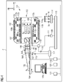
- FIG. 4 shows (including in particular the technical background) a (in a shielded room or Faraday cage F befindliches) imaging magnetic resonance apparatus MRT 101 with a hollow cylinder 102 with a tubular space 103 in which a patient couch 104 with a body such as an object to be examined (eg Patients) 105 (with or without local coil arrangement 106) can be moved in the direction of the arrow z in order to generate images of the patient 105 by means of an imaging method.
- a local coil arrangement 106 is arranged on the patient 105, with which MR images of a partial area of the body 105 in the FoV can be generated in a local area (also called field of view or FoV).
- Signals of the local coil arrangement 106 can be evaluated by an evaluation device (168, 115, 117, 119, 120, 121, etc.) of the MRT 101 that can be connected to the local coil arrangement 106 via coaxial cable or by radio (167) etc. (eg converted into images, stored or displayed).
- a strong magnet (often a cryomagnet 107) in a measuring booth with a tunnel-shaped opening 103 here generates a static strong main magnetic field B 0 , which is eg 0.2 Tesla to 3 Tesla or even more.
- a body 105 to be examined is mounted on a patient couch 104 in a viewing area FoV (also called "Field Of View” or "field of view”) approximately homogeneous region of the main magnetic field B0.
- An excitation of the nuclear spins of atomic nuclei of the body 105 via magnetic high-frequency excitation pulses B1 (x, y, z, t) via a here as (eg multi-part 108a, 108b, 108c) body coil 108 very simplified illustrated high-frequency antenna (and / or if necessary, a local coil arrangement) are irradiated.
- High-frequency excitation pulses are generated, for example, by a pulse generation unit 109 which is controlled by a pulse sequence control unit 110. After being amplified by a high-frequency amplifier 111, they are sent to the high-frequency antenna 108.
- the high-frequency system shown here is only indicated schematically. It is also possible that more than one pulse generating unit 109, more than one high-frequency amplifier 111 and a plurality of high-frequency antennas 108 a, b, c are used in a magnetic resonance apparatus 101.
- the magnetic resonance device 101 has gradient coils 112x, 112y, 112z with which magnetic gradient fields B G (x, y, z, t) for selective slice excitation and for spatial coding of the measured signal are radiated during a measurement.
- the gradient coils 112x, 112y, 112z become is controlled by a gradient coil control unit 114 (and possibly via amplifiers Vx, Vy, Vz) which, like the pulse generation unit 109, is connected to the pulse sequence control unit 110.
- Signals emitted by the excited nuclear spins are received by the body coil 108 and / or at least one local coil arrangement 106, amplified by associated high-frequency preamplifiers 116 and further processed and digitized by a receiving unit 117.
- the recorded measurement data are digitized and stored as complex numerical values in a k-space matrix. From the k-space matrix occupied with values, a corresponding MR image can be reconstructed by means of a multi-dimensional Fourier transformation.
- the correct signal transmission is controlled by an upstream transceiver 118.
- An image processing unit 119 generates from the measurement data an image that is displayed to a user via an operating console 120 and / or stored in a memory unit 121.
- a central computer unit 122 controls the individual system components.
- a switching matrix (sometimes called RCCS) is installed between receiving antennas and receiver, for example. This routes the currently active receive channels (usually those that are currently in the field of view of the magnet) to the existing receivers. This makes it possible to connect more coil elements than receivers are present, since in a full-body coverage only the coils must be read, which are located in the FoV or in the homogeneity volume of the magnet.
- a local coil arrangement 106 is generally referred to, for example, an antenna system, which may consist of one or as an array coil of a plurality of antenna elements (esp. Coil elements), for example. These individual antenna elements are designed, for example, as loop antennas (loops), butterfly, flex coils or saddle coils.
- a local coil arrangement comprises, for example, coil elements, a preamplifier, further electronics (standing wave barriers, etc.), a housing, supports and usually a cable with plug, by means of which it is connected to the MRT system.
- a receiver 168 mounted on the system filters and digitizes a signal received by a local coil 106, for example by radio etc., and transmits the data of a digital signal processing device which usually derives an image or a spectrum from the data obtained by a measurement and for example for subsequent diagnosis by the user provides him and / or storage.
- FIG. 1-4 show some details of exemplary embodiments of the invention.
- unwanted patient movement during image acquisition can cause severe image artifacts.
- Such unwanted motion artifacts can also be caused by respiration in the chest or abdominal area. Therefore, it may be useful to detect the patient's breathing and to synchronize the (MRI) image acquisition with the respiration cycle. This can be particularly helpful for magnetic resonance imaging (MRI) because imaging (MRI) can take several minutes and not every patient can hold their breath for so long.
- MRI magnetic resonance imaging
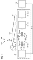
- Fig. 1 shows an embodiment of the invention with a placement here one or alternatively a plurality of RF resonators (resonant circuits) HF-Res in the vicinity of the patient 105 in the chest region BrB and / or abdominal region BaB.
- the RF resonator HF-Res (and / or the motion sensor AS with evaluation electronics) can be integrated into the patient couch 104 of a magnetic resonance tomography apparatus 101, for example.
- an RF signal from an RF generator (RF-Si-Srs) for example, via a coupling coil Cpl-In (or capacitive with eg a coupling capacitor or with other coupling) coupled.
- the RF signal generated in the HF generator RF-Si-Srs and coupled into the RF resonator HF-Res is coupled out again from the HF resonator (inductively or capacitively with, for example, a coupling capacitor or with a different coupling). out) and with the eg narrow-band RF detector (RF-Filt and / or HF-Dtect) filtered and detected.
- the eg narrow-band RF detector RF-Filt and / or HF-Dtect
- WW Properties (WW, in this case in particular quality) of the RF resonator are influenced here by the respiration of the patient and thereby also changes the transmission (S21) of the RF signal via the RF resonator (ie the difference S21diff between S21-e in the patient who has inhaled compared to S21-a in the patient who has exhaled).
- This arrangement allows a measurement of the transmission losses of the RF resonator HF-Res, as in Fig. 1 is shown.
- the RF resonator HF-Res is constructed here so that the induced electromagnetic field RF-Si of the RF resonator HF-Res enters the body of the patient 105 so that an interaction WW between the RF resonator HF-Res and the body of the Patient 105 is enabled.
- a body movement AB (as well as a breathing movement or a displacement of the anatomy within the body, which could not be visible to the outside) then causes a change in the loaded quality of the RF resonator HF-Res.
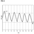
- breathing movements AB of the patient 105 may be considered as in Fig. 3 shown temporal changes S21-diff of transmission S21-e-S21-a (before and after inhalation) over time t [s] are measured.
- the resonance frequency of the RF resonator HF-Res differs from the MR frequency of the magnetic resonance tomography device 101, so that little or as far as possible no mutual interference between the motion sensor or respiratory sensor AS and MR imaging arises can.
- the RF resonator HF-Res behaves e.g. as an inductive or capacitive sensor and not (or hardly) like an MRI imaging antenna (106) because of the inductive (or capacitive) near field. This minimizes radiated RF energy.
- Embodiments of the invention may be sensitive to respiration because the measured transmission losses of an RF resonator HF-Res depend on the air-tissue distribution;
- the muscle tissue can have large RF losses compared to the inhaled air.
- a transmission measurement does not require a directional coupler such as a measurement of the reflection factor and may be less sensitive to mismatches in a measurement path.
- Transmittance measurements according to the invention are feasible in a wide dynamic range and may be less ambiguous (zero crossing and sign change) than a measurement of the reflection factor.
- An HF resonator HF-Res can work similarly to an inductive sensor with negligible radiation, insofar as only the near field is necessary for the function.
- Embodiments of the invention may have a negligible impact on the SAR balance (as opposed to MR navigators) insofar as the used RF signals may have low power (eg, 1mW).
- a motion sensor AS can be integrated in a patient couch 104.
- the body distance can always be the same and in comparison with other methods, no new visible wiring will be necessary.
- the distance between a movement sensor AS and a patient 105 can be very constant in a motion sensor AS integrated in a patient couch 104, in particular in comparison to the alternative of placing the sensor above the patient behind the bore cover.
- Fig. 1 For example, an RF filter RF-Filt and an RF detector HF-Detect for detecting an RF signal are generally shown.
Abstract
Die Erfindung betrifft Verfahren und einen Bewegungssensor (AS) zur Detektion von Bewegungen (AB) eines Patienten (105) in einem bildgebenden medizinischen System, insbesondere in einem Magnetresonanztomographiesystem (101), dadurch gekennzeichnet, dass er (AS) mindestens einen HF-Resonator (HF-Res) zum Senden eines von einer HF-Signal-Quelle (HF-Si-Srs) in ihn eingespeisten (CPL-in) HF-Signals (HF-Si) und zum Empfang (CPL-out, HF-Filt, HF-Dtect) eines Antwort-Signals (HF-Ressi) aufweist, und dass er (AS) eine Detektionseinrichtung (HF-Filt, HF-Detect) zur Detektion von Bewegungen (AB) des Patienten (105) aufweist.The invention relates to methods and a movement sensor (AS) for detecting movements (AB) of a patient (105) in an imaging medical system, in particular in a magnetic resonance imaging system (101), characterized in that it (AS) comprises at least one RF resonator (RF-Res) for transmitting a (CPL-in) RF signal (RF-Si.) fed thereto from an RF signal source (RF-Si-Srs) ) and for the reception (CPL-out, RF-Filt, HF-Dtect) of a response signal (RF-Ressi), and that it (AS) comprises a detection device (HF-Filt, HF-Detect) for the detection of movements ( AB) of the patient (105).
Description
Die Erfindung betrifft Bewegungssensoren und Verfahren zur Erfassung von Bewegungen eines Patienten in einem bildgebenden medizinischen System, insbesondere Magnetresonanztomographiesystem.The invention relates to motion sensors and methods for detecting movements of a patient in an imaging medical system, in particular magnetic resonance tomography system.
Verfahren zur Erfassung von Bewegungen (insbesondere zur Atemerfassung) in einem Magnetresonanztomographiesystem sind beispielsweise in folgenden Schriften beschrieben:
- Die Veröffentlichung
Buikman, Helzel, Röschmann: The Coil as a Sensitive Motion Detector for MRI-Magnetic-Resonance-Imaging, Vol. 6, Num. 3, 1988
- The publication
Buikman, Helzel, Röschmann: The Coil as a Sensitive Motion Detector for MRI Magnetic Resonance Imaging, Vol. 6, Num. 3, 1988
Es ist eine Aufgabe der vorliegenden Erfindung, ein medizinisches Gerät (insbesondere Magnetresonanztomographiesystem) hinsichtlich einer Bewegungserfassung zu optimieren. Diese Aufgabe wird jeweils durch die Merkmale der unabhängigen Patentansprüche gelöst. Ausgestaltungen der Erfindung können eine zu bestehenden Varianten alternative, effiziente Bewegungserfassung ermöglichen. Vorteilhafte Weiterbildungen sind in den Unteransprüchen und der nachfolgenden Beschreibung angegeben.It is an object of the present invention to optimize a medical device (in particular magnetic resonance tomography system) with regard to movement detection. This object is achieved in each case by the features of the independent patent claims. Embodiments of the invention may provide alternative, efficient motion detection to existing variants enable. Advantageous developments are specified in the subclaims and the following description.
Weitere Merkmale und Vorteile von möglichen Ausgestaltungen der Erfindung ergeben sich aus der nachfolgenden Beschreibung von Ausführungsbeispielen anhand der Zeichnung. Dabei zeigt:
- Fig. 1
- ein Ausführungsbeispiel einer Messanordnung mit einem offenen LC-Resonator,
- Fig. 2
- gemessene Änderungen der Transmission S21 durch eine Körperbewegung,
- Fig. 3
- gemessene zeitliche Änderungen der Transmission S21 durch Atmung,
- Fig. 4
- schematisch ein MRT-System.
- Fig. 1
- an embodiment of a measuring arrangement with an open LC resonator,
- Fig. 2
- Measured changes in transmission S21 due to body movement,
- Fig. 3
- Measured temporal changes of the transmission S21 by respiration,
- Fig. 4
- schematically an MRI system.
Um mit einem Magnetresonanzgerät MRT 101 einen Körper 105 (ein Untersuchungsobjekt oder einen Patienten) mittels einer Magnet-Resonanz-Bildgebung zu untersuchen, werden verschiedene, in ihrer zeitlichen und räumlichen Charakteristik genauestens aufeinander abgestimmte Magnetfelder auf den Körper 105 eingestrahlt. Ein starker Magnet (oft ein Kryomagnet 107) in einer Messkabine mit einer hier tunnelförmigen Öffnung 103, erzeugt ein statisches starkes Hauptmagnetfeld B0, das z.B. 0,2 Tesla bis 3 Tesla oder auch mehr beträgt. Ein zu untersuchender Körper 105 wird auf einer Patientenliege 104 gelagert in einen im Betrachtungsbereich FoV (auch "Field Of View" oder "field of view" genannt) etwa homogenen Bereich des Hauptmagnetfeldes B0 gefahren. Eine Anregung der Kernspins von Atomkernen des Körpers 105 erfolgt über magnetische Hochfrequenz-Anregungspulse B1(x, y, z, t) die über eine hier als (z.B. mehrteilige = 108a, 108b, 108c) Körperspule 108 sehr vereinfacht dargestellte Hochfrequenzantenne (und/oder ggf. eine Lokalspulenanordnung) eingestrahlt werden. Hochfrequenz-Anregungspulse werden z.B. von einer Pulserzeugungseinheit 109 erzeugt, die von einer Pulssequenz-Steuerungseinheit 110 gesteuert wird. Nach einer Verstärkung durch einen Hochfrequenzverstärker 111 werden sie zur Hochfrequenzantenne 108 geleitet. Das hier gezeigte Hochfrequenzsystem ist lediglich schematisch angedeutet. Möglicherweise werden auch mehr als eine Pulserzeugungseinheit 109, mehr als ein Hochfrequenzverstärker 111 und mehrere Hochfrequenzantennen 108 a, b, c in einem Magnet-Resonanz-Gerät 101 eingesetzt.In order to examine a body 105 (an examination subject or a patient) by means of a magnetic resonance imaging with a magnetic
Weiterhin verfügt das Magnet-Resonanz-Gerät 101 über Gradientenspulen 112x, 112 y, 112 z, mit denen bei einer Messung magnetische Gradientenfelder BG(x, y, z, t) zur selektiven Schichtanregung und zur Ortskodierung des Messsignals eingestrahlt werden. Die Gradientenspulen 112x, 112y, 112z werden von einer Gradientenspulen-Steuerungseinheit 114 (und ggf. über Verstärker Vx, Vy, Vz) gesteuert, die ebenso wie die Pulserzeugungseinheit 109 mit der Pulssequenz-Steuerungseinheit 110 in Verbindung steht.Furthermore, the
Von den angeregten Kernspins (der Atomkerne im Untersuchungsobjekt) ausgesendete Signale werden von der Körperspule 108 und/oder mindestens einer Lokalspulenanordnung 106 empfangen, durch zugeordnete Hochfrequenzvorverstärker 116 verstärkt und von einer Empfangseinheit 117 weiterverarbeitet und digitalisiert. Die aufgezeichneten Messdaten werden digitalisiert und als komplexe Zahlenwerte in einer k-Raum-Matrix abgelegt. Aus der mit Werten belegten k-Raum-Matrix ist mittels einer mehrdimensionalen Fourier-Transformation ein zugehöriges MR-Bild rekonstruierbar.Signals emitted by the excited nuclear spins (of the atomic nuclei in the examination subject) are received by the body coil 108 and / or at least one
Für eine Spule, die sowohl im Sende- als auch im Empfangsmodus betrieben werden kann, wie z.B. die Körperspule 108 oder eine Lokalspule 106, wird die korrekte Signalweiterleitung durch eine vorgeschaltete Sende-Empfangs-Weiche 118 geregelt.For a coil that can be operated in both the transmit and receive modes, e.g. the body coil 108 or a
Eine Bildverarbeitungseinheit 119 erzeugt aus den Messdaten ein Bild, das über eine Bedienkonsole 120 einem Anwender dargestellt und/oder in einer Speichereinheit 121 gespeichert wird. Eine zentrale Rechnereinheit 122 steuert die einzelnen Anlagekomponenten.An
In der MR-Tomographie werden Bilder mit hohem Signal/Rauschverhältnis (SNR) heute in der Regel mit so genannten Lokalspulenanordnungen (Coils, Local Coils) aufgenommen. Dies sind Antennensysteme, die in unmittelbarer Nähe auf (anterior) oder unter (posterior) oder an oder in dem Körper 105 angebracht werden. Bei einer MR-Messung induzieren die angeregten Kerne in den einzelnen Antennen der Lokalspule eine Spannung, die dann mit einem rauscharmen Vorverstärker (z.B. LNA, Preamp) verstärkt und schließlich an die Empfangselektronik weitergeleitet wird. Zur Verbesserung des Signal/Rauschverhältnisses auch bei hochaufgelösten Bildern werden so genannte Hochfeldanlagen eingesetzt (1.5T-12T oder mehr). Wenn an ein MR-Empfangssystem mehr Einzelantennen angeschlossen werden können, als Empfänger vorhanden sind, wird zwischen Empfangsantennen und Empfänger z.B. eine Schaltmatrix (teilweise auch RCCS genannt) eingebaut. Diese routet die momentan aktiven Empfangskanäle (meist die, die gerade im Field of View des Magneten liegen) auf die vorhandenen Empfänger. Dadurch ist es möglich, mehr Spulenelemente anzuschließen, als Empfänger vorhanden sind, da bei einer Ganzkörperabdeckung nur die Spulen ausgelesen werden müssen, die sich im FoV bzw. im Homogenitätsvolumen des Magneten befinden.In MR tomography, images with a high signal-to-noise ratio (SNR) are generally recorded today with so-called local coil arrangements (coils, local coils). These are antenna systems that are mounted in close proximity on (anterior) or below (posterior) or on or in the
Als Lokalspulenanordnung 106 wird z.B. allgemein ein Antennensystem bezeichnet, das z.B. aus einem oder als Array-Spule aus mehreren Antennenelementen (insb. Spulenelementen) bestehen kann. Diese einzelnen Antennenelemente sind z.B. als Loopantennen (Loops), Butterfly, Flexspulen oder Sattelspulen ausgeführt. Eine Lokalspulenanordnung umfasst z.B. Spulenelemente, einen Vorverstärker, weitere Elektronik (Mantelwellensperren etc.), ein Gehäuse, Auflagen und meistens ein Kabel mit Stecker, durch den sie an die MRT-Anlage angeschlossen wird. Ein anlagenseitig angebrachte Empfänger 168 filtert und digitalisiert ein von einer Lokalspule 106 z.B. per Funk etc. empfangenes Signal und übergibt die Daten einer digitalen Signalverarbeitungseinrichtung die aus den durch eine Messung gewonnenen Daten meist ein Bild oder ein Spektrum ableitet und dem Nutzer z.B. zur nachfolgenden Diagnose durch ihn und/ oder Speicherung zur Verfügung stellt.As a
Bei der medizinischen Bildgebung können ungewünschte Patienten-Bewegung während der Bildaufnahme starke Bildartefakte verursachen. Solche ungewünschte Bewegungsartefakte können im Brust- oder Bauch-Bereich auch durch Atmung verursacht werden. Deshalb kann es sinnvoll sein, die Patienten-Atmung zu detektieren und die (MRT-)Bildaufnahme mit dem Atmung-Zyklus zu synchronisieren. Das kann insbesondere hilfreich sein für Magnetresonanztomographie (MRT), weil die Bildaufnahme (MR-Sequenz) einige Minuten dauern kann und nicht jeder Patient den Atem so lange anhalten kann.In medical imaging, unwanted patient movement during image acquisition can cause severe image artifacts. Such unwanted motion artifacts can also be caused by respiration in the chest or abdominal area. Therefore, it may be useful to detect the patient's breathing and to synchronize the (MRI) image acquisition with the respiration cycle. This can be particularly helpful for magnetic resonance imaging (MRI) because imaging (MRI) can take several minutes and not every patient can hold their breath for so long.
Eigenschaften (WW, wie hier insbesondere Güte) des HF-Resonators werden hier durch die Atmung des Patienten beeinflusst und dadurch ändert sich auch die Transmission (S21) des HF-Signals über den HF-Resonator (also die Differenz S21diff zwischen S21-e beim Patienten der eingeatmet hat im Vergleich zu S21-a beim Patienten der ausgeatmet hat). Diese Anordnung ermöglicht eine Messung der Transmissionsverluste des HF-Resonators HF-Res, wie in
Der HF-Resonator HF-Res ist hier so aufgebaut, dass das induzierte elektromagnetische Feld HF-Si des HF-Resonators HF-Res in den Körper des Patienten 105 eindringt damit eine Wechselwirkung WW zwischen dem HF-Resonator HF-Res und dem Körper des Patienten 105 ermöglicht wird. Eine Körperbewegung AB (wie auch z.B. eine Atembewegung oder eine Verschiebung der Anatomie innerhalb des Körpers, die nach außen auch nicht sichtbar sein könnte) verursacht dann hier eine Änderung der belasteten Güte des HF-Resonators HF-Res.The RF resonator HF-Res is constructed here so that the induced electromagnetic field RF-Si of the RF resonator HF-Res enters the body of the
Das kann z.B. wie in
Ferner können Atembewegungen AB des Patienten 105 als in
Wenn die Abmessungen des benutzten HF-Resonators HF-Res deutlich kleiner sind als die benutzte Wellenlänge des Messsignals, dann verhält sich der HF-Resonator HF-Res z.B. als ein induktiver oder kapazitiver Sensor und nicht (oder kaum) wie eine MRT-Bildgebungs-Antenne (106), weil man im induktiven (bzw. kapazitiven) Nahfeld arbeitet. Dadurch wird die abgestrahlte HF-Energie minimiert.If the dimensions of the used RF resonator HF-Res are significantly smaller than the used wavelength of the measurement signal, then the RF resonator HF-Res behaves e.g. as an inductive or capacitive sensor and not (or hardly) like an MRI imaging antenna (106) because of the inductive (or capacitive) near field. This minimizes radiated RF energy.
Ausgestaltungen der Erfindung können sensibel für die Atmung sein, weil die gemessenen Transmissionsverluste eines HF-Resonators HF-Res von der Luft-Gewebe-Verteilung abhängig sind; das Muskel-Gewebe kann große HF-Verluste im Vergleich mit der eingeatmeten Luft haben.Embodiments of the invention may be sensitive to respiration because the measured transmission losses of an RF resonator HF-Res depend on the air-tissue distribution; The muscle tissue can have large RF losses compared to the inhaled air.
Eine Transmissionsmessung benötigt keinen Richtkoppler wie eine Messung des Reflexionsfaktors und kann weniger empfindlich auf Fehlanpassungen in einer Messstrecke sein. Erfindungsgemäße Transmissionsmessungen sind in eine großen Dynamikbereich durchführbar und können weniger mehrdeutig (Nulldurchgang und Vorzeichenänderung) als eine Messung des Reflexionsfaktors sein.A transmission measurement does not require a directional coupler such as a measurement of the reflection factor and may be less sensitive to mismatches in a measurement path. Transmittance measurements according to the invention are feasible in a wide dynamic range and may be less ambiguous (zero crossing and sign change) than a measurement of the reflection factor.
Ein HF-Resonator HF-Res kann ähnlich wie ein induktiver Sensor mit einer vernachlässigbaren Abstrahlung arbeiten, insoweit nur das Nahfeld für die Funktion notwendig ist.An HF resonator HF-Res can work similarly to an inductive sensor with negligible radiation, insofar as only the near field is necessary for the function.
Eine berührungslose Messung kann ermöglicht werden. Der Atemsensor muss nicht auf dem Körper eines Patienten 105 platziert und befestigt werden.A non-contact measurement can be made possible. The respiratory sensor need not be placed and secured on the body of a
Ausgestaltungen der Erfindung können einen vernachlässigbaren Einfluss auf die SAR-Bilanz haben (im Gegensatz zu MR-Navigatoren) haben, insoweit die benutzten HF-Signale eine geringe Leistung haben kann (von z.B. 1mW).Embodiments of the invention may have a negligible impact on the SAR balance (as opposed to MR navigators) insofar as the used RF signals may have low power (eg, 1mW).
Ein Bewegungssensor AS kann in einer Patientenliege 104 integriert sein. Derart kann der Körper-Abstand immer gleich sein und im Vergleich mit anderen Methoden keine neue sichtbare Verkabelung notwendig werden. Der Abstand zwischen einem Bewegungssensor AS und einem Patient 105 kann bei einem in einer Patientenliege 104 integrierten Bewegungssensor AS sehr konstant sein, insbesondere im Vergleich zu der Alternative, den Sensor oberhalb des Patienten hinter der Bore-Verkleidung zu platzieren.A motion sensor AS can be integrated in a
Wie eine Transmissionsmessung ausführbar sein könnte, ist dem Fachmann an sich bekannt z.B. auch aus www.wikipedia.de; im Prinzip werden z.B. S-Parameter wie z.B. der Vorwärts-Transmissionsfaktor S21 mit Hilfe von Netzwerkanalysatoren als Funktion der Frequenz gemessen, s. z.B. in http://de.wikipedia.org/wiki/Netzwerkanalysator#mediaviewer/F ile:Vna3.png dargestellte Netzwerkanalysatoren, es können aber auch beliebige andere Netzwerkanalanalysatoren erwogen werden.How a transmission measurement could be carried out is known to the person skilled in the art, for example, from www.wikipedia.de; In principle, for example, S-parameters such as the forward transmission factor S21 are measured as a function of frequency with the help of network analyzers, eg in network analyzers shown in http://en.wikipedia.org/wiki/Network_Analyzer#mediaviewer/File:Vna3.png However, any other network analyzer can be considered.
In
Claims (21)
dadurch gekennzeichnet,
dass er (AS) mindestens einen HF-Resonator (HF-Res) zum Senden eines von einer HF-Signal-Quelle (HF-Si-Srs) in ihn eingespeisten (CPL-in) HF-Signals (HF-Si)
und zum Empfang (CPL-out, HF-Filt, HF-Dtect) des Signals (HF-Si) aufweist,
und dass er (AS) eine Detektionseinrichtung (HF-Filt, HF-Detect) zur Detektion von Bewegungen (AB) des Patienten (105) aufweist.Motion sensor (AS) for detecting movements (AB) of a patient (105) in an imaging medical system, in particular in a magnetic resonance imaging system (101),
characterized,
in that it (AS) has at least one RF resonator (HF-Res) for transmitting a (CPL-in) RF signal (HF-Si) fed into it from an HF signal source (HF-Si-Sr).
and for receiving (CPL-out, RF-Filt, RF-Dtect) the signal (HF-Si),
and that it (AS) has a detection device (RF-Filt, RF-Detect) for detecting movements (AB) of the patient (105).
dadurch gekennzeichnet,
dass sich die Frequenz des vom HF-Resonator (HF-Res) sendbaren HF-Signals (HF-Si) sich von der Frequenz von sendbaren Hochfrequenz-Anregungspulsen B1(x, y, z, t) des medizinischen System in Form eines Magnetresonanztomographiegeräts (101, 108) unterscheidet.Motion sensor according to claim 1,
characterized,
in that the frequency of the RF signal (RF-Si) which can be transmitted by the RF resonator (RF-Si) is dependent on the frequency of the radio-frequency excitable RF pulses B1 (x, y, z, t) of the medical system in the form of a magnetic resonance tomography apparatus ( 101, 108).
dadurch gekennzeichnet, dass
genau einer oder mehrere HF-Resonatoren (HF-Res) vorgesehen sind.Motion sensor according to one of the preceding claims,
characterized in that
exactly one or more RF resonators (RF-Res) are provided.
der HF-Resonator (HF-Res) einen LC-Resonator mit mindestens einer Spule (LR) und mindestens einem Kondensator (CR) aufweist.Motion sensor according to one of the preceding claims, characterized in that
the RF resonator (RF-Res) an LC resonator having at least one coil (LR) and at least one capacitor (CR).
dadurch gekennzeichnet, dass
ein vom HF-Resonator (HF-Res) empfangenes HF-Signal (HF-Si) mit einem vorzugsweise schmalbandigen HF-Detektor (HF-Filt, HF-Dtect) detektiert wird.Motion sensor according to one of the preceding claims,
characterized in that
a RF signal (HF-Si) received by the RF resonator (HF-Res) is detected with a preferably narrowband RF detector (RF-Filt, HF-Dtect).
dadurch gekennzeichnet, dass
Unterschiede (S21diff) des detektierten HF-Signals (HF-Si) im eingeatmeten und ausgeatmeten Zustand des Patienten gemessen werden.Motion sensor according to one of the preceding claims,
characterized in that
Differences (S21diff) of the detected RF signal (HF-Si) in the patient's inspired and exhaled states can be measured.
dadurch gekennzeichnet, dass
der HF-Resonator (HF-Res) so aufgebaut ist, dass das induzierte elektromagnetische Feld (HF-Si) des HF-Resonators (HF-Res) in den Körper des Patienten (105) eindringt, damit eine Wechselwirkung (WW) zwischen dem Resonator (HF-Res) und dem Körper des Patienten (105) ermöglicht wird.Motion sensor according to one of the preceding claims,
characterized in that
the RF resonator (RF-Res) is constructed so that the induced electromagnetic field (RF-Si) of the RF resonator (RF-Res) penetrates into the body of the patient (105), so that an interaction (WW) between the Resonator (HF-Res) and the body of the patient (105) is made possible.
dadurch gekennzeichnet, dass
mindestens ein HF-Resonator (HF-Res) in der Nähe und/oder unterhalb des Brust-Bereichs (BrB) und/oder Bauch-Bereichs (BaB) eines Patienten (105) angeordnet ist.Motion sensor according to one of the preceding claims,
characterized in that
at least one RF resonator (RF-Res) is arranged in the vicinity of and / or below the breast region (BrB) and / or abdominal region (BaB) of a patient (105).
dadurch gekennzeichnet, dass
der Bewegungssensor (AS) in einer Patientenliege (104) eines Magnetresonanztomographiesystems (101) angeordnet ist.Motion sensor according to one of the preceding claims,
characterized in that
the movement sensor (AS) is arranged in a patient couch (104) of a magnetic resonance tomography system (101).
dadurch gekennzeichnet, dass
ein HF-Resonator (HF-Res) oberhalb des Patienten hinter der Bore-Verkleidung des Magnetresonanztomographiesystems (101) angeordnet ist.Motion sensor according to one of the preceding claims,
characterized in that
an RF resonator (RF-Res) is disposed above the patient behind the boron cover of the magnetic resonance imaging system (101).
dadurch gekennzeichnet, dass
er dazu ausgebildet ist, eine Körperbewegung und/oder eine Verschiebung der Anatomie innerhalb des Körpers eines Patienten (105) durch eine Änderung der belasteten Güte des HF-Resonators (HF-Res) und/oder eines Transmissionsfaktors (S21) zu detektieren.Motion sensor according to one of the preceding claims,
characterized in that
it is designed to detect a body movement and / or a displacement of the anatomy within the body of a patient (105) by a change in the loaded quality of the RF resonator (HF-Res) and / or a transmission factor (S21).
dadurch gekennzeichnet, dass
er dazu ausgebildet (119) ist, eine Körperbewegung oder eine Verschiebung der Anatomie innerhalb des Körpers eines Patienten (105) aufgrund einer zeitlichen Änderungen der Transmission (S21) zu detektieren. (Fig. 3)Motion sensor according to one of the preceding claims,
characterized in that
it is adapted (119) to detect a body movement or a displacement of the anatomy within the body of a patient (105) due to a temporal change of the transmission (S21). (Fig. 3)
dadurch gekennzeichnet, dass
die Abmessungen des HF-Resonators (HF-Res) kleiner sind als die Wellenlänge des HF-Signals (HF-Si).Motion sensor according to one of the preceding claims,
characterized in that
the dimensions of the RF resonator (HF-Res) are smaller than the wavelength of the RF signal (HF-Si).
dadurch gekennzeichnet, dass
der HF-Resonator (HF-Res) dazu ausgebildet ist, als ein induktiver und/oder kapazitiver Sensor im induktiven und/oder kapazitiven Nahfeld zu arbeiten.Motion sensor according to one of the preceding claims,
characterized in that
the RF resonator (RF-Res) is designed to operate as an inductive and / or capacitive sensor in the inductive and / or capacitive near field.
dadurch gekennzeichnet, dass
er dazu ausgebildet ist, eine Atmungsbewegung eines Patienten (105) eines MRT (101) berührungslos zu messen.Motion sensor according to one of the preceding claims,
characterized in that
it is designed to contactlessly measure a respiratory movement of a patient (105) of an MRT (101).
dadurch gekennzeichnet, dass
die benutzten HF-Signale eine Leistung von weniger als 10 mW, insbesondere maximal 1mW haben.Motion sensor according to one of the preceding claims,
characterized in that
the used RF signals have a power of less than 10 mW, in particular a maximum of 1 mW.
dadurch gekennzeichnet, dass
er ein Atemsensor zur Erfassung von Atembewegungen eines Patienten (105) in einem MRT (101) ist.Motion sensor according to one of the preceding claims,
characterized in that
it is a respiratory sensor for detecting respiratory movements of a patient (105) in an MRI (101).
dadurch gekennzeichnet, dass
er mit einem Magnetresonanztomographiesystem (101) verbunden ist, das dazu ausgebildet (119) ist, eine aufgrund einer zeitlichen Änderungen der Transmission (S21) detektierte gemessene Körperbewegung und/oder Verschiebung der Anatomie innerhalb des Körpers eines Patienten (105) bei einer Korrektur von mit dem Magnetresonanztomographiesystem (101) bestimmten Bilddaten zur Erzeugung von Bildern des Körpers des Patienten (105) zu berücksichtigen.Motion sensor according to one of the preceding claims,
characterized in that
it is connected to a magnetic resonance imaging system (101) adapted (119) for a measured body movement detected by a temporal change of the transmission (S21) and / or displacement of the anatomy within the body of a patient (105) with a correction of the magnetic resonance imaging system (101) to take into account image data for generating images of the body of the patient (105).
dadurch gekennzeichnet, dass
das bildgebende medizinische System ein Magnetresonanztomographiesystem (101) ist.Motion sensor according to one of the preceding claims,
characterized in that
the medical imaging system is a magnetic resonance imaging system (101).
dadurch gekennzeichnet, dass die Einkoppelung des HF-Signals (HF-Si) in den HF-Resonator (HF-Res) und/oder die Auskoppelung des HF-Signals (HF-Si) aus dem HF-Resonator
induktiv (Cpl-in, Cpl-out) oder kapazitiv oder mit einer andere Koppelung vorgesehen ist.Motion sensor according to one of the preceding claims,
characterized in that the coupling of the RF signal (HF-Si) in the RF resonator (HF-Res) and / or the decoupling of the RF signal (HF-Si) from the RF resonator
Inductive (Cpl-in, Cpl-out) or capacitive or provided with another coupling.
dadurch gekennzeichnet, dass ein Bewegungssensor (AS) nach einem der vorhergehenden Ansprüche verwendet wird.Method for detecting movements (AB) of a patient (105) in an imaging medical system, in particular in a magnetic resonance tomography system (101),
characterized in that a movement sensor (AS) according to one of the preceding claims is used.
Applications Claiming Priority (1)
| Application Number | Priority Date | Filing Date | Title |
|---|---|---|---|
| DE102015200510.0A DE102015200510A1 (en) | 2015-01-15 | 2015-01-15 | motion sensor |
Publications (1)
| Publication Number | Publication Date |
|---|---|
| EP3045929A1 true EP3045929A1 (en) | 2016-07-20 |
Family
ID=54936789
Family Applications (1)
| Application Number | Title | Priority Date | Filing Date |
|---|---|---|---|
| EP15199836.6A Withdrawn EP3045929A1 (en) | 2015-01-15 | 2015-12-14 | Sensor for the detection of movements of a patient in an imaging system |
Country Status (5)
| Country | Link |
|---|---|
| US (1) | US20160209486A1 (en) |
| EP (1) | EP3045929A1 (en) |
| JP (1) | JP2016131880A (en) |
| CN (1) | CN105796104A (en) |
| DE (1) | DE102015200510A1 (en) |
Families Citing this family (6)
| Publication number | Priority date | Publication date | Assignee | Title |
|---|---|---|---|---|
| US10264200B2 (en) * | 2016-12-23 | 2019-04-16 | Omnivision Technologies, Inc. | Random sampling for horizontal noise reduction |
| EP3486672A1 (en) * | 2017-11-16 | 2019-05-22 | Koninklijke Philips N.V. | Magnetic resonance imaging system with rf motion detection |
| WO2020131250A2 (en) | 2018-12-19 | 2020-06-25 | Hyperfine Research, Inc. | System and methods for grounding patients during magnetic resonance imaging |
| US11419516B2 (en) * | 2019-08-26 | 2022-08-23 | GE Precision Healthcare LLC | MRI system comprising patient motion sensor |
| AU2020363637A1 (en) * | 2019-10-08 | 2022-03-24 | Hyperfine Operations, Inc. | System and methods for detecting electromagnetic interference in patients during magnetic resonance imaging |
| US20210124001A1 (en) * | 2019-10-25 | 2021-04-29 | Hyperfine Research, Inc. | Systems and methods for detecting patient motion during magnetic resonance imaging |
Citations (8)
| Publication number | Priority date | Publication date | Assignee | Title |
|---|---|---|---|---|
| EP0186238A2 (en) * | 1984-12-21 | 1986-07-02 | Philips Patentverwaltung GmbH | Method of producing a movement signal and nuclear spin tomograph for such a method |
| DE4238831A1 (en) * | 1992-11-17 | 1994-05-19 | Siemens Ag | HF arrangement for NMR tomography appts - includes surface coil inductively coupled to HF transmission antenna, and electronic switch for damping |
| US5575287A (en) * | 1993-01-25 | 1996-11-19 | Fonar Corporation | Inductively coupled RF coils for magnetic resonance studies |
| US6023166A (en) * | 1997-11-19 | 2000-02-08 | Fonar Corporation | MRI antenna |
| WO2011033422A1 (en) * | 2009-09-17 | 2011-03-24 | Koninklijke Philips Electronics N.V. | Mr imaging system comprising physiological sensors |
| DE102009052412A1 (en) | 2009-10-02 | 2011-04-07 | Universität Duisburg-Essen | Measuring system for use in magnetic resonance tomograph to detect position of heart in human being, has detector detecting detuning or impedance of antenna or signals as measuring signals to determine position of heart in human being |
| WO2013190451A1 (en) * | 2012-06-21 | 2013-12-27 | Koninklijke Philips N.V. | Magnetic resonance examination system with motion detection |
| DE102014209488A1 (en) | 2014-05-20 | 2015-11-26 | Siemens Aktiengesellschaft | Method for measuring the breathing process of a patient during a magnetic resonance examination, measuring arrangement and magnetic resonance device |
Family Cites Families (6)
| Publication number | Priority date | Publication date | Assignee | Title |
|---|---|---|---|---|
| US20100106008A1 (en) * | 2007-03-20 | 2010-04-29 | Koninklijke Philips Electronics N.V. | Magnetic resonance imaging system and method |
| DE102009019896A1 (en) * | 2009-05-04 | 2010-11-18 | Siemens Aktiengesellschaft | Device for use in diagnostic magnetic resonance device to detect heart movements of patient, has signal analysis unit extracting signal corresponding to heart movements of patient from changes caused by heart movements |
| DE102009048150A1 (en) * | 2009-10-02 | 2011-04-07 | Siemens Aktiengesellschaft | Accelerator and method for controlling an accelerator |
| EP2578148A1 (en) * | 2011-10-04 | 2013-04-10 | Koninklijke Philips Electronics N.V. | Medical imaging system with motion detection |
| JP2013228226A (en) * | 2012-04-24 | 2013-11-07 | Toshiba Corp | Pet-mri apparatus |
| CN104248436A (en) | 2013-06-26 | 2014-12-31 | 西门子公司 | Respiratory cycle collection |
-
2015
- 2015-01-15 DE DE102015200510.0A patent/DE102015200510A1/en not_active Withdrawn
- 2015-12-14 EP EP15199836.6A patent/EP3045929A1/en not_active Withdrawn
-
2016
- 2016-01-12 JP JP2016003376A patent/JP2016131880A/en active Pending
- 2016-01-14 CN CN201610023557.6A patent/CN105796104A/en active Pending
- 2016-01-14 US US14/995,408 patent/US20160209486A1/en not_active Abandoned
Patent Citations (8)
| Publication number | Priority date | Publication date | Assignee | Title |
|---|---|---|---|---|
| EP0186238A2 (en) * | 1984-12-21 | 1986-07-02 | Philips Patentverwaltung GmbH | Method of producing a movement signal and nuclear spin tomograph for such a method |
| DE4238831A1 (en) * | 1992-11-17 | 1994-05-19 | Siemens Ag | HF arrangement for NMR tomography appts - includes surface coil inductively coupled to HF transmission antenna, and electronic switch for damping |
| US5575287A (en) * | 1993-01-25 | 1996-11-19 | Fonar Corporation | Inductively coupled RF coils for magnetic resonance studies |
| US6023166A (en) * | 1997-11-19 | 2000-02-08 | Fonar Corporation | MRI antenna |
| WO2011033422A1 (en) * | 2009-09-17 | 2011-03-24 | Koninklijke Philips Electronics N.V. | Mr imaging system comprising physiological sensors |
| DE102009052412A1 (en) | 2009-10-02 | 2011-04-07 | Universität Duisburg-Essen | Measuring system for use in magnetic resonance tomograph to detect position of heart in human being, has detector detecting detuning or impedance of antenna or signals as measuring signals to determine position of heart in human being |
| WO2013190451A1 (en) * | 2012-06-21 | 2013-12-27 | Koninklijke Philips N.V. | Magnetic resonance examination system with motion detection |
| DE102014209488A1 (en) | 2014-05-20 | 2015-11-26 | Siemens Aktiengesellschaft | Method for measuring the breathing process of a patient during a magnetic resonance examination, measuring arrangement and magnetic resonance device |
Non-Patent Citations (1)
| Title |
|---|
| BUIKMAN; HELZEL; RÖSCHMANN, THE COIL AS A SENSITIVE MOTION DETECTOR FOR MRI-MAGNETIC-RESONANCE-IMAGING, vol. 6, no. 3, 1988 |
Also Published As
| Publication number | Publication date |
|---|---|
| JP2016131880A (en) | 2016-07-25 |
| US20160209486A1 (en) | 2016-07-21 |
| DE102015200510A1 (en) | 2016-07-21 |
| CN105796104A (en) | 2016-07-27 |
Similar Documents
| Publication | Publication Date | Title |
|---|---|---|
| EP3045929A1 (en) | Sensor for the detection of movements of a patient in an imaging system | |
| DE102012211147B4 (en) | Automatic detuning of unconnected transmit-receive coils for MRI | |
| DE102012207722B3 (en) | Whole-body coil for MRI apparatus e.g. functional MRI apparatus used for performing investigation of patient, has radio frequency antenna whose capacitance is changed by changing distance of RF-screen | |
| DE102010004515B4 (en) | Spine coil array for MRI applications with enhanced imaging capabilities for dedicated body regions | |
| DE102010004514A1 (en) | Dynamic tracking of the HF adjustment with parallel transmission | |
| DE102012200600A1 (en) | MRI local coil position detection in an MRI system | |
| DE102011079564B4 (en) | MRT local coil | |
| DE102012206066A1 (en) | Detection of unmated local coils in a magnetic resonance tomograph | |
| DE102013217555B3 (en) | Combined shim and RF coil elements | |
| DE102012215004A1 (en) | Detection of the static position of transmitter / receiver coils of a magnetic resonance tomograph with the aid of electronically readable labels | |
| DE102012204527B4 (en) | Multi-ply cushion for optimal adaptation to anatomy and susceptibility adjustment | |
| DE102014210657A1 (en) | Axis-displaceable local coil | |
| DE102012215007A1 (en) | Detecting the position of transmitter / receiver coils of a magnetic resonance tomograph with the aid of labels read in motion | |
| DE102012208325A1 (en) | Automatic positioning and adaptation in a calibration procedure for a Shim field map based on AutoAlign and AutoCoverage | |
| DE102013218226A1 (en) | Compatible magnetic resonance receiver | |
| DE102012215006A1 (en) | Detection of transmitter / receiver coils of a magnetic resonance tomograph with the aid of electronically readable labels | |
| DE102010004664B4 (en) | Flow sensor for cooling water in a gradient coil | |
| DE102009019896A1 (en) | Device for use in diagnostic magnetic resonance device to detect heart movements of patient, has signal analysis unit extracting signal corresponding to heart movements of patient from changes caused by heart movements | |
| DE102013217012B4 (en) | Local SAR reduction for e.g. Patients with metallic implants | |
| DE102014216402B4 (en) | Signal processing in a magnetic resonance tomography device | |
| DE102013213907A1 (en) | Automatic local coil isocentering | |
| DE102014207843B4 (en) | Knee Coil | |
| DE102014202716A1 (en) | Improve local SAR behavior of MRI transmit coils by using orthogonal loop antennas | |
| DE102010063724B4 (en) | Local coil and method for changing the inner diameter of a local coil | |
| DE102014223878A1 (en) | Phase monitoring for multi-channel MR transmission systems |
Legal Events
| Date | Code | Title | Description |
|---|---|---|---|
| PUAI | Public reference made under article 153(3) epc to a published international application that has entered the european phase |
Free format text: ORIGINAL CODE: 0009012 |
|
| AK | Designated contracting states |
Kind code of ref document: A1 Designated state(s): AL AT BE BG CH CY CZ DE DK EE ES FI FR GB GR HR HU IE IS IT LI LT LU LV MC MK MT NL NO PL PT RO RS SE SI SK SM TR |
|
| AX | Request for extension of the european patent |
Extension state: BA ME |
|
| STAA | Information on the status of an ep patent application or granted ep patent |
Free format text: STATUS: THE APPLICATION IS DEEMED TO BE WITHDRAWN |
|
| 18D | Application deemed to be withdrawn |
Effective date: 20170121 |