EP3045864A1 - Flight path search device and flight path search program - Google Patents
Flight path search device and flight path search program Download PDFInfo
- Publication number
- EP3045864A1 EP3045864A1 EP16150535.9A EP16150535A EP3045864A1 EP 3045864 A1 EP3045864 A1 EP 3045864A1 EP 16150535 A EP16150535 A EP 16150535A EP 3045864 A1 EP3045864 A1 EP 3045864A1
- Authority
- EP
- European Patent Office
- Prior art keywords
- cell
- enemy
- score
- flight path
- cells
- Prior art date
- Legal status (The legal status is an assumption and is not a legal conclusion. Google has not performed a legal analysis and makes no representation as to the accuracy of the status listed.)
- Granted
Links
Images


Classifications
-
- G—PHYSICS
- G01—MEASURING; TESTING
- G01C—MEASURING DISTANCES, LEVELS OR BEARINGS; SURVEYING; NAVIGATION; GYROSCOPIC INSTRUMENTS; PHOTOGRAMMETRY OR VIDEOGRAMMETRY
- G01C21/00—Navigation; Navigational instruments not provided for in groups G01C1/00 - G01C19/00
- G01C21/20—Instruments for performing navigational calculations
-
- G—PHYSICS
- G08—SIGNALLING
- G08G—TRAFFIC CONTROL SYSTEMS
- G08G5/00—Traffic control systems for aircraft, e.g. air-traffic control [ATC]
- G08G5/003—Flight plan management
- G08G5/0034—Assembly of a flight plan
-
- G—PHYSICS
- G01—MEASURING; TESTING
- G01C—MEASURING DISTANCES, LEVELS OR BEARINGS; SURVEYING; NAVIGATION; GYROSCOPIC INSTRUMENTS; PHOTOGRAMMETRY OR VIDEOGRAMMETRY
- G01C21/00—Navigation; Navigational instruments not provided for in groups G01C1/00 - G01C19/00
- G01C21/38—Electronic maps specially adapted for navigation; Updating thereof
- G01C21/3863—Structures of map data
- G01C21/387—Organisation of map data, e.g. version management or database structures
- G01C21/3881—Tile-based structures
Landscapes
- Engineering & Computer Science (AREA)
- Radar, Positioning & Navigation (AREA)
- Remote Sensing (AREA)
- Physics & Mathematics (AREA)
- General Physics & Mathematics (AREA)
- Automation & Control Theory (AREA)
- Databases & Information Systems (AREA)
- Aviation & Aerospace Engineering (AREA)
- Traffic Control Systems (AREA)
- Navigation (AREA)
Abstract
Description
- The present invention relates to a flight path search device and flight path search method to search for a flight path for entry to an enemy region where an attack from enemy forces is conceivable.
- Conventionally, flight paths for aircraft have been set taking into consideration various conditions, such as the flight environment of the aircraft, geographical features along the route, and so forth. Various technologies have been proposed relating to this point (see Japanese Unexamined Patent Application Publication
JP 2003-099 900 A JP 3 557 444 B2 JP 2 812 639 B2 - However, the above conventional technology does not assume application to military aircraft, and does not take into consideration safety regarding attacks from enemy forces. Accordingly, the conventional related art does not provide for searching for an optimal flight path for entry to an enemy region where an attack from enemy forces is conceivable such that a target point can be quickly reached while avoiding attacks.
- It is desirable to enable searching for an optimal flight path for entry to an enemy region where an attack from enemy forces is conceivable.
- A first aspect of the present invention provides a flight path search device that is adapted to search for a flight path of an aircraft, from outside of an enemy region including an enemy forces point to a predetermined point within the enemy region. The flight path search device includes:
- a storage unit that is adapted to store map information of a predetermined range,
- and enemy force range information; a grid divider that is adapted to divide the map information stored in the storage, into cells in grid form on a horizontal plane;
- a score calculator that is adapted to calculate a score relating to an attack avoidance degree, for each of the cells, based on the map information and enemy force range information stored in the storage;
- a cell calculator that is adapted to calculate a second cell that is situated on an extension of a straight line connecting the enemy forces point and a first cell within the enemy region, on the map information, and is situated outside of the enemy region, the extension extending towards the first cell; a searcher that is adapted to search for, among adjacent cells adjacent to the first cell on the map information, an optimal cell to which to move from the first cell when moving from the first cell toward the second cell, based on the score calculated by the score calculator; and
- an updater that is adapted to update the first cell by setting the optimal cell as a new first cell, in a case where the optimal cell found by the searcher does not agree with the second cell.
- The cell where the predetermined point is situated is set as the first point, and the calculating of the second cell by the cell calculator, the searching for the optimal cell by the searcher using the second cell, and the updating of the first cell by the updater, are repeated until the optimal cell found by the searcher agrees with the second cell.
- The score calculator may calculate the score for each of the adjacent cells adjacent to the first cell, each time the updater updates the first cell. The searcher may search for the optimal cell based on the scores of each of the adjacent cells calculated by the score calculator.
- The score calculator may calculate the score relating to attack avoidance degree of the each of the cells, based on both a score relating to distance between the first cell and the each of the cells, and a score relating to a degree of threat of enemy forces present at the enemy forces point. The score relating to the degree of threat of enemy forces may be calculated based on both a score relating to distance between the enemy forces and the each of the cells, and a score relating to geographical features of the each of the cells from the perspective of avoiding attack.
- A second aspect of the present invention provides a flight path search program that is adapted to search for a flight path of an aircraft, from outside of an enemy region including an enemy forces point to a predetermined point within the enemy region.
- The program is adapted to cause a computer, including storage that stores map information of a predetermined range and enemy force range information, to perform the following steps:
- a grid dividing function of dividing the map information stored in the storage, into a cells in grid form on a horizontal plane;
- a score calculating function of calculating a score relating to an attack avoidance degree, for each of the cells, based on the map information and enemy force range information stored in the storage;
- a cell calculating function of calculating a second cell that is situated on an extension of a straight line connecting the enemy forces point and a first cell within the enemy region, on the map information, and is situated outside of the enemy region, the extension extending towards the first cell; a searching function of searching for, among adjacent cells adjacent to the first cell on the map information, an optimal cell to which to move from the first cell when moving from the first cell toward the second cell, based on the score calculated by the score calculating function; and an updating function of updating the first cell by setting the optimal cell as a new first cell, in a case where the optimal cell found by the searching function does not agree with the second cell.
- The cell where the predetermined point is situated is set as the first point, and the calculating of the second cell by the cell calculating function, the searching for the optimal cell by the searching function using the second cell, and the updating of the first cell by the updating function, are repeated until the optimal cell found by the searching function agrees with the second cell.
-
- FIG. 1
- is a block diagram illustrating a functional configuration of an aircraft according to an embodiment of the present invention;
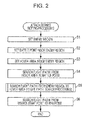
- FIG. 2
- is a flowchart illustrating the flow of attack details setting processing;
- FIG. 3
- is a diagram for describing attack details setting processing;
- FIG. 4
- is a flowchart illustrating the flow of flight path search setting processing;
- FIGS. 5A to 5F
- are diagrams for describing flight path search processing; and
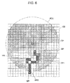
- FIG. 6
- is a diagram for describing flight path search processing.
- An implementation of the present invention will be described with reference to the drawings.
- The configuration of a flight path search device according to an embodiment of the present invention will be described with reference to
FIG. 1 . In the drawings,FIG. 1 is a block diagram illustrating the functional configuration of anaircraft 10 to which the flight path search device according to an embodiment of the present invention has been applied. - The
aircraft 10 in the embodiment is a military rotorcraft (attack helicopter) bearing armament, that carries out missions to start moving from a predetermined mission start point, and attack a target existing at a target point TP within later-described enemy region ADU (seeFIG. 3 , etc.). More specifically, theaircraft 10 includes aflight mechanism 11, aweaponry launch mechanism 12, anoperating unit 13, adisplay unit 14, astorage unit 15, acontrol unit 18, and so forth, as illustrated inFIG. 1 . Theflight mechanism 11 is a mechanism that causes theaircraft 10 to fly, and primarily includes a main rotor that generates lift necessary for the aircraft to fly, and an internal combustion engine (e.g., a jet engine) that generates thrust. - The
weaponry launch mechanism 12 is a mechanism to launch rockets, missiles, and so forth, with which theaircraft 10 is armed. - The
operating unit 13 includes a control stick, various types of operating keys, and so forth. Signals corresponding to the operation state of this control stick, various types of operating keys, and so forth, are output to thecontrol unit 18. Thedisplay unit 14 includes a display that is omitted from illustration, and displays various types of information on the display based on display signals input from thecontrol unit 18. - The
storage unit 15 is memory that stores programs and data to realize the various functions of theaircraft 10, and also functions as work area. Thestorage unit 15 according to the present embodiment stores an attackdetails setting program 150,map data 155, and so forth. - The attack
details setting program 150 is a program that causes thecontrol unit 18 to execute later-described attack details setting processing (seeFIG. 2 ). The attackdetails setting program 150 has a flightpath search program 151 according to the embodiment of the present invention. The flightpath search program 151 is a program that causes thecontrol unit 18 to execute later-described flight path search processing (seeFIG. 4 ). - The
map data 155 has comprehensive geographical information including, in addition to land features such as mountains, rivers, and so forth, information relating to the state of usage of land, such as roads and railways, buildings, fields, and so forth. Themap data 155 may be information of a regional range relating to the mission, i.e., a predetermined range including at least a target point TP within later-described and enemy region ADU (seeFIG. 3 ). - The
storage unit 15 also stores various types of information necessary for the later-described attack details setting processing, such as coordinates of the mission start point and so forth, information of the range of enemy forces within the enemy region ADU, and so forth. - The
control unit 18 centrally controls the parts of theaircraft 10. Specifically, thecontrol unit 18 performs such as controlling the operations of theflight mechanism 11, theweaponry launch mechanism 12, and so forth, loading a specified program from programs stored in thestorage unit 15 and executing various processes cooperatively with the loaded program, and so forth, based on pilot operations at the operatingunit 13. - Next, operations at the time of the
aircraft 10 performing the attack details setting processing will be described with reference toFIGS. 2 to 6 .FIG. 2 is a flowchart illustrating the flow of attack details setting processing, andFIG. 3 is a diagram for describing attack details setting processing.FIG. 4 is a flowchart illustrating the flow of flight path search setting processing, andFIGS. 5A to 6 are diagrams for describing flight path search processing. - The attack details setting processing is processing to set an optimal battle point BP for carrying out an attack on a target point TP which is an enemy forces point, and then searching and setting a flight path to this battle point BP. This attack details setting processing is executed by the
control unit 18 reading out and loading the attack details settingprogram 150 from thestorage unit 15 upon an execution instruction for the attack details setting processing being input by pilot operations. - Upon the attack details setting processing being performed, first, as illustrated in
FIGS. 2 and3 , thecontrol unit 18 sets an enemy region ADU within a predetermined range including a target point TP (step S1). An enemy region ADU is a geographical range regarding which there is a possibility of being attacked by enemy forces, primarily at the target point TP. The enemy region ADU may be calculated based on enemy force range information and so forth stored in thestorage unit 15 or directly input by the pilot, and set. Thecontrol unit 18 then stores the set enemy region ADU in thestorage unit 15. - Next, the
control unit 18 sets a battle point BP within the enemy region ADU, for carrying out an attack on the target point TP (step S2). The battle point BP may be calculated based onmap data 155 and enemy force range information and so forth stored in thestorage unit 15 or directly input by the pilot, and set. Thecontrol unit 18 then stores the coordinates of the battle point BP that has been set in thestorage unit 15. - The
control unit 18 next sets a hover area HA within the enemy region ADU, from which the battle point BP is visible (step S3). This hover area HA in the present embodiment is a point at a distance within a predetermined amount of time from the battle point BP by flying hugging the ground, and from which the battle point BP is visible. This hover area HA may be calculated based onmap data 155 and enemy force range information and so forth stored in thestorage unit 15 or directly input by the pilot, and set. Thecontrol unit 18 then stores the coordinates of the hover area HA that has been set in thestorage unit 15. - Next, the
control unit 18 searches for a first flight path FP 1 from the hover area HA to the battle point BP (step S4). The first flight path FP1 is searched for by predetermined search processing, as a path from the battle point BP to the hover area HA, which is the opposite direction to the actual flight direction. This first flight path FP1 may be searched for in the same way as a second flight path FP2 in step S5, to be described later. - The
control unit 18 next executes flight path search processing, to search for a second flight path FP2 from a waypoint WP outside of the enemy region ADU to the hover area HA inside of the enemy region ADU (step S5). - The waypoint WP is undetermined at the and the present point, and is searched and set as the same time as the second flight path FP2 in the flight path search processing, as a point outside of the enemy region ADU, from which the enemy region ADU can be safely and quickly entered as far as the hover area HA.
- This flight path search processing is executed by the
control unit 18 reading out and loading the flightpath search program 151 from thestorage unit 15 upon an execution instruction for the flight path search processing being input by pilot operations. - Upon the flight path search processing being executed, the
control unit 18 first reads themap data 155 from thestorage unit 15, and divides themap data 155 into a grid form of multiple cells C in a horizontal plane, as illustrated inFIG. 4 (step S51). Thecontrol unit 18 generates the multiple cells C as a square grid along the division lines that run north-south and east-west on themap data 155 in the embodiment. Each square is 50 meters each way. The shape of the cells does not have to be square, as long as a grid is realized. For example, a rhombic grid, a hexagonal grid (honeycomb), or the like, may be used. - The
control unit 18 next initially sets a cell C where the hover area HA exists as a current location cell Cp for the search processing (step S52,FIG. 5A ). The current location cell Cp is a tentative current location for theaircraft 10 in the search processing. The current location cell Cp is dynamically changed by the following processing whereby a path from the hover area HA to outside of the enemy region ADU, which is opposite to the actual flight direction, is searched. - Next, the
control unit 18 calculates a score P relating to the attack avoidance degree of each of the multiple cells C adjacent to the current location cell Cp, based on themap data 155 and enemy force range information stored in the storage unit 15 (step S53). - The score P indicates the likelihood of the
aircraft 10 being attacked by enemy forces when flying from the current location cell Cp to this cell C, and the lower the value is, the more readily attack is avoided, i.e., the safer the cell C is. More specifically, thecontrol unit 18 calculates the score of the cell C in step S53 using the following Expression (1)

- P2 is a score relating to the degree of threat of the target existing at the target point TP, and is calculated by the following Expression (3)

- The closer the distance from the target point TP to the cell C is in in linear distance, the larger the value set to P21 is. Specifically, P21 is set using a table or relational expression in which this distance and the score P21 have been correlated. P22 is set based on the
map data 155 and enemy force range information stored in thestorage unit 15. - The geographical feature state of the cell C is selected from the following items (1) through (4) in the present embodiment. The score of the cell C is set in descending order from (1) to (4).
- (1) Exposed to at least one enemy regardless of altitude
- (2) Not exposed to any enemy, but cannot gain altitude above 150 feet.
- (3) Can gain altitude above 150 feet without being exposed to any enemy, but the enemy sees sky when ascending from exposure height to 100 feet.
- (4) Can gain altitude above 150 feet without being exposed to any enemy, and also the enemy does not see sky when ascending from exposure height to 100 feet.
- Next, the
control unit 18 calculates a destination point cell Cg corresponding to the current location cell Cp at the current point (step S54). Specifically, thecontrol unit 18 calculates the closest cell C which is on a straight line connecting the target point TP and the current location cell Cp on themap data 155, extended to the current location cell Cp side, and which is situated outside of the enemy region ADU (FIG. 5A ), as destination point cell Cg. - The
control unit 18 then searches for a cell C to move to next from the current location cell Cp, based on the scores P of the multiple cells C relating to the attack avoidance degree calculated in step S53 (step S55). Specifically, thecontrol unit 18 finds, of the multiple cells C adjacent to the current location cell Cp on themap data 155, a cell C optimal to move to from the current location cell Cp when moving from the current location cell Cp to the destination point cell Cg, as the smallest score P on this path of movement. The present embodiment uses the A* (pronounced "A-star") search algorithm, which is a representative search algorithm, for this search. - The
control unit 18 next determines whether or not the cell C found in step S55 and the destination point cell Cg agree (step S56), and if determined to not agree (NO in step S56), the found cell C is updated to the current location cell Cp as a new current location cell Cp (step S57,FIG. 5B ), and the flow returns to step S53 described above. - That is to say, in this case the processing of steps S53 to S57 is repeated until the current location cell Cp agrees with the destination point cell Cg at that time (
FIGS. 5C to 5F ). Note thatFIGS. 5A to 5F use difference in darkness of hatching to illustrate the magnitude in score at cells C other than cells C adjacent to the current location cell Cp as well, in a simplified manner. - In a case where the
control unit 18 determines that the cell C found in step S55 agrees with the destination point cell Cg (YES in step S56), this found cell C is set as the waypoint WP and the path from the hover area HA to the waypoint WP is set as the second flight path FP2, as illustrated inFIG. 6 (step S58), and the flight path search processing ends. - Next, the
control unit 18 executes the attack details setting processing again, and searches for a third flight path FP3 that is omitted from illustration (step S6). The third flight path FP3 is searched for by predetermined search processing, as a path from the mission start point to the waypoint WP, which is the opposite direction to the actual flight direction. - This third flight path FP3 may be searched for in the same way as the second flight path FP2 described above in step S5. Thus, a flight path made up of the first flight path FP1, the second flight path FP2, and the third flight path FP3, from the mission start point to the battle point BP within the enemy region ADU, is set.
- As described above, according to the present embodiment, the
map data 155 is first divided into a grid form of multiple cells C in a horizontal plane, and scores P relating to the attack avoidance degree of each of the multiple cells C, based on themap data 155 and enemy force range information. Calculation of a destination point cell Cg which is on a straight line connecting the target point TP within the enemy region ADU and the current location cell Cp and which is situated outside of the enemy region, searching for a cell C optimal to move to from the current location cell Cp when moving from the current location cell Cp to the destination point cell Cg, based on the score P, and updating this cell C to a new current location cell Cp in a case where this optimal cell C does not agree with the destination point cell Cg, are repeated. - That is to say, the current location cell Cp within the enemy region ADU is set as a tentative current location, and the closest point (destination point cell Cg) for linearly moving away from the target point TP to the outside of the enemy region ADU is set as a tentative destination point. This is dynamically changed to successively calculate the destination of movement where the attack avoidance degree is the highest when heading to this closest point, as the new current location cell Cp, up to outside of the enemy region ADU.
- Accordingly, by setting the cell C where the hover area HA is situated as the current location cell Cp, the second flight path FP2 heading from outside of the enemy region ADU to the hover area HA inside of the enemy region ADU is searched as a flight path where outside of the enemy region ADU can be safely and speedily reached from the hover area HA, in the opposed direction from the actual flight direction. Accordingly, an optimal flight path can be searched for entry to the enemy region ADU where an attack from enemy forces is conceivable.
- Note that embodiments to which the present invention is applicable are not restricted to the above-described implementation, and that modifications may be made as necessary without departing from the essence of the present invention. For example, while description has been made above that the first current location cell Cp is set as the hover area HA, the initial current location cell Cp is not restricted in particular as long as it is a predetermined point within the enemy region ADU, and if there is no hover area HA, may be set to the battle point BP.
- Also, while description has been made that the
aircraft 10 carries out an attack on the target point TP within the enemy region ADU, it is sufficient that the aircraft according to the present invention enters an enemy region including an enemy forces point, and may be for reconnaissance alone, or the like, for example. - Also, while an example has been described where the flight path search device according to the present invention is applied to an
aircraft 10, the flight path search device according to the present invention is not restricted to this arrangement, and for example may be provided within ground equipment that performs communication with theaircraft 10, or the like. -
- 10
- aircraft
- 11
- flight mechanism
- 12
- weaponry launch mechanism
- 13
- operating unit
- 14
- display unit
- 15
- storage unit
- 18
- control unit
- 150
- attack details setting program
- 151
- flight path program data
- 155
- map data
- ADU
- enemy region
- BP
- battle point
- C
- cell
- Cg
- destination point cell
- Cp
- current location cell
- FP1
- first flight path
- FP2
- second flight path
- TP
- target point
- WP
- way point
Claims (4)
- A flight path search device that is adapted to search for a flight path of an aircraft (10), from outside of an enemy region including an enemy forces point to a predetermined point within the enemy region, the flight path search device comprising:- storage unit that is adapted to store map information (155) of a predetermined range, and enemy force range information;- a grid divider that is adapted to divide the map information (155) stored in the storage unit, into cells (C)in grid form on a horizontal plane;- a score calculator that is adapted to calculate a score (P) relating to an attack avoidance degree, for each of the cells (C), based on the map information (155) and enemy force range information stored in the storage;- a cell calculator that is adapted to calculate a second cell that is situated on an extension of a straight line connecting the enemy forces point and a first cell within the enemy region, on the map information, and is situated outside of the enemy region, the extension extending towards the first cell;- a searcher that is adapted to search for, among adjacent cells adjacent to the first cell on the map information (155), an optimal cell to which to move from the first cell when moving from the first cell toward the second cell, based on the score (P) calculated by the score calculator; and- an updater that is adapted to update the first cell by setting the optimal cell as a new first cell, in a case where the optimal cell found by the searcher does not agree with the second cell,wherein
the cell where the predetermined point is situated is set as the first cell, and the calculating of the second cell by the cell calculator,
the searching for the optimal cell by the searcher using the second cell, and the updating of the first cell by the updater,
are repeated until the optimal cell found by the searcher agrees with the second cell. - The flight path search device according to claim 1,
wherein the score calculator is adapted to calculate the score (P) for each of the adjacent cells adjacent to the first cell, each time the updater updates the first cell, and
the searcher is adapted to search for the optimal cell based on the scores (P) of each of the adjacent cells calculated by the score calculator. - The flight path search device according to either of claims 1 and 2,
wherein the score calculator is adapted to calculate the score (P) relating to attack avoidance degree of the each of the cells, based on both a score (P) relating to distance between the first cell and the each of cells, and a score (P) relating to a degree of threat of enemy forces present at the enemy forces point, and
the score (P) relating to the degree of threat of enemy forces is calculated based on both a score (P) relating to distance between the enemy forces and the each of the cells, and a score (P) relating to geographical features of the each of the cells from the perspective of avoiding attack. - A machine readable flight path search program (151) that is adapted to search for a flight path of an aircraft (10), from outside of an enemy region (ADU) including an enemy forces point to a predetermined point within the enemy region, the program being adapted to cause a computer, including a storage unit (15) that stores map information (155) of a predetermined range and enemy force range information, to perform the following steps:- a grid dividing function of dividing the map information (155) stored in the storage unit (15), into cells in grid form on a horizontal plane;- a score calculating function of calculating a score (P) relating to an attack avoidance degree, for each of the cells, based on the map information (155) and enemy force range information stored in the storage unit (15);- a cell calculating function of calculating a second cell that is situated on an extension of a straight line connecting the enemy forces point and a first cell within the enemy region, on the map information (155), and is situated outside of the enemy region (ADU), the extension extending towards the first cell;- a searching function of searching for, among adjacent cells adjacent to the first cell on the map information (155), an optimal cell to which to move from the first cell when moving from the first cell toward the second cell, based on the score (P) calculated by the score calculating function; and- an updating function of updating the first cell by setting the optimal cell as a new first cell, in a case where the optimal cell found by the searching function does not agree with the second cell,wherein
the cell where the predetermined point is situated is set as the first point, and
the calculating of the second cell by the cell calculating function,
the searching for the optimal cell by the searching function using the second cell, and
the updating of the first cell by the updating function,
are repeated until the optimal cell found by the searching function agrees with the second cell.
Applications Claiming Priority (1)
| Application Number | Priority Date | Filing Date | Title |
|---|---|---|---|
| JP2015006340A JP6073387B2 (en) | 2015-01-16 | 2015-01-16 | Flight path search device and flight path search program |
Publications (2)
| Publication Number | Publication Date |
|---|---|
| EP3045864A1 true EP3045864A1 (en) | 2016-07-20 |
| EP3045864B1 EP3045864B1 (en) | 2017-11-15 |
Family
ID=55077432
Family Applications (1)
| Application Number | Title | Priority Date | Filing Date |
|---|---|---|---|
| EP16150535.9A Active EP3045864B1 (en) | 2015-01-16 | 2016-01-08 | Flight path search device and flight path search program |
Country Status (3)
| Country | Link |
|---|---|
| US (1) | US9711052B2 (en) |
| EP (1) | EP3045864B1 (en) |
| JP (1) | JP6073387B2 (en) |
Cited By (3)
| Publication number | Priority date | Publication date | Assignee | Title |
|---|---|---|---|---|
| CN107272025A (en) * | 2017-06-05 | 2017-10-20 | 浙江百世技术有限公司 | A kind of driving trace detection method of regular bus/bus |
| CN111143500A (en) * | 2019-12-27 | 2020-05-12 | 中国联合网络通信集团有限公司 | Visualized area calculation method, terminal, control device and storage medium |
| CN112684789A (en) * | 2019-10-17 | 2021-04-20 | 诺基亚通信公司 | Controlling movement of a device |
Families Citing this family (9)
| Publication number | Priority date | Publication date | Assignee | Title |
|---|---|---|---|---|
| US11327508B2 (en) * | 2015-09-29 | 2022-05-10 | University Of Malta | Fast flight trajectory optimisation for in-flight computation and flight management systems |
| JP6200539B1 (en) * | 2016-03-24 | 2017-09-20 | 株式会社Subaru | Reconnaissance position calculation device, reconnaissance position calculation method, and reconnaissance position calculation program |
| JP6788540B2 (en) * | 2017-03-30 | 2020-11-25 | 株式会社Subaru | Patrol route setting device, patrol route setting method and patrol route setting program |
| JP6894970B2 (en) * | 2017-04-20 | 2021-06-30 | エスゼット ディージェイアイ テクノロジー カンパニー リミテッドSz Dji Technology Co.,Ltd | Flight path determination method, information processing device, program and recording medium |
| CN110192161B (en) * | 2017-05-31 | 2022-04-22 | 深圳市大疆创新科技有限公司 | Method and system for operating a movable platform using ray casting mapping |
| CN107885194B (en) * | 2017-11-10 | 2020-10-20 | 广东工业大学 | Unmanned exploration device and control method and system thereof |
| CN109655063B (en) * | 2018-11-12 | 2023-10-27 | 中航通飞华南飞机工业有限公司 | Marine search route planning method for large amphibious aircraft |
| WO2020103034A1 (en) * | 2018-11-21 | 2020-05-28 | 深圳市道通智能航空技术有限公司 | Method and device for planning path of unmanned aerial vehicle, and unmanned aerial vehicle |
| CN116362390B (en) * | 2023-03-20 | 2023-09-12 | 中国人民解放军军事科学院战略评估咨询中心 | Marine volt-ampere prediction method and system based on probabilistic neural network |
Citations (9)
| Publication number | Priority date | Publication date | Assignee | Title |
|---|---|---|---|---|
| JP2812639B2 (en) | 1993-06-15 | 1998-10-22 | 三菱電機株式会社 | Route search system and route search method |
| JP2003099900A (en) | 2001-09-21 | 2003-04-04 | Mitsubishi Heavy Ind Ltd | Flight route setting method |
| JP3557444B2 (en) | 2001-10-25 | 2004-08-25 | 防衛庁技術研究本部長 | Method and apparatus for creating low altitude flight path |
| US20050150997A1 (en) * | 2002-02-08 | 2005-07-14 | Saab Ab | Method and system for calculating a flight route |
| US20060116814A1 (en) * | 2003-04-09 | 2006-06-01 | Milbert Randy L | Method and system for generating and presenting off-road travel routes |
| US7194353B1 (en) * | 2004-12-03 | 2007-03-20 | Gestalt, Llc | Method and system for route planning of aircraft using rule-based expert system and threat assessment |
| US20110029234A1 (en) * | 2009-07-29 | 2011-02-03 | Lockheed Martin Corporation | Threat Analysis Toolkit |
| US20130124089A1 (en) * | 2011-11-11 | 2013-05-16 | Lockheed Martin Corporation | Spatiotemporal survivability data compression using objective oriented constraints |
| JP2015001377A (en) * | 2013-06-13 | 2015-01-05 | 富士重工業株式会社 | Flight route searching apparatus, and flight route searching program |
Family Cites Families (3)
| Publication number | Priority date | Publication date | Assignee | Title |
|---|---|---|---|---|
| JPH06149376A (en) * | 1992-11-05 | 1994-05-27 | Mitsubishi Electric Corp | Path generating device |
| US6963800B1 (en) * | 2002-05-10 | 2005-11-08 | Solider Vision | Routing soldiers around enemy attacks and battlefield obstructions |
| US9070101B2 (en) * | 2007-01-12 | 2015-06-30 | Fatdoor, Inc. | Peer-to-peer neighborhood delivery multi-copter and method |
-
2015
- 2015-01-16 JP JP2015006340A patent/JP6073387B2/en active Active
- 2015-12-15 US US14/970,258 patent/US9711052B2/en active Active
-
2016
- 2016-01-08 EP EP16150535.9A patent/EP3045864B1/en active Active
Patent Citations (9)
| Publication number | Priority date | Publication date | Assignee | Title |
|---|---|---|---|---|
| JP2812639B2 (en) | 1993-06-15 | 1998-10-22 | 三菱電機株式会社 | Route search system and route search method |
| JP2003099900A (en) | 2001-09-21 | 2003-04-04 | Mitsubishi Heavy Ind Ltd | Flight route setting method |
| JP3557444B2 (en) | 2001-10-25 | 2004-08-25 | 防衛庁技術研究本部長 | Method and apparatus for creating low altitude flight path |
| US20050150997A1 (en) * | 2002-02-08 | 2005-07-14 | Saab Ab | Method and system for calculating a flight route |
| US20060116814A1 (en) * | 2003-04-09 | 2006-06-01 | Milbert Randy L | Method and system for generating and presenting off-road travel routes |
| US7194353B1 (en) * | 2004-12-03 | 2007-03-20 | Gestalt, Llc | Method and system for route planning of aircraft using rule-based expert system and threat assessment |
| US20110029234A1 (en) * | 2009-07-29 | 2011-02-03 | Lockheed Martin Corporation | Threat Analysis Toolkit |
| US20130124089A1 (en) * | 2011-11-11 | 2013-05-16 | Lockheed Martin Corporation | Spatiotemporal survivability data compression using objective oriented constraints |
| JP2015001377A (en) * | 2013-06-13 | 2015-01-05 | 富士重工業株式会社 | Flight route searching apparatus, and flight route searching program |
Non-Patent Citations (1)
| Title |
|---|
| "AI Programming Wisdom 4", 20 February 2008, CHARLES RIVER MEDIA, article FERNS PAANAKKER: "Risk-Adverse Pathfinding Using Influence Maps", pages: 173 - 178, XP055277511 * |
Cited By (6)
| Publication number | Priority date | Publication date | Assignee | Title |
|---|---|---|---|---|
| CN107272025A (en) * | 2017-06-05 | 2017-10-20 | 浙江百世技术有限公司 | A kind of driving trace detection method of regular bus/bus |
| CN112684789A (en) * | 2019-10-17 | 2021-04-20 | 诺基亚通信公司 | Controlling movement of a device |
| EP3809231A1 (en) * | 2019-10-17 | 2021-04-21 | Nokia Solutions and Networks Oy | Controlling movement of a device |
| US11662726B2 (en) | 2019-10-17 | 2023-05-30 | Nokia Solutions And Networks Oy | Controlling movement of a device |
| CN111143500A (en) * | 2019-12-27 | 2020-05-12 | 中国联合网络通信集团有限公司 | Visualized area calculation method, terminal, control device and storage medium |
| CN111143500B (en) * | 2019-12-27 | 2023-07-18 | 中国联合网络通信集团有限公司 | Visual area calculation method, terminal, control device and storage medium |
Also Published As
| Publication number | Publication date |
|---|---|
| JP2016133321A (en) | 2016-07-25 |
| US20160210865A1 (en) | 2016-07-21 |
| US9711052B2 (en) | 2017-07-18 |
| EP3045864B1 (en) | 2017-11-15 |
| JP6073387B2 (en) | 2017-02-01 |
Similar Documents
| Publication | Publication Date | Title |
|---|---|---|
| EP3045864B1 (en) | Flight path search device and flight path search program | |
| Zarchan | Tactical and strategic missile guidance | |
| Yanushevsky | Guidance of unmanned aerial vehicles | |
| JP5822676B2 (en) | Multistage rocket guidance device, multistage rocket guidance program, multistage rocket guidance method, and multistage rocket guidance system | |
| EP3045865B1 (en) | Route point setting device and route point setting program | |
| CN105005651A (en) | Gradient separate zone optimization design method for spacecraft pulse rendezvous trajectory | |
| JP2015001377A (en) | Flight route searching apparatus, and flight route searching program | |
| CN110822994B (en) | Linear pseudo-spectrum spreading control guidance method with falling angle constraint | |
| US20160210866A1 (en) | Navigational aid method depending on meteorological conditions | |
| Karelahti et al. | Automated generation of realistic near-optimal aircraft trajectories | |
| Gaudet et al. | Integrated Guidance and Control for Lunar Landing using a Stabilized Seeker | |
| JP2017172877A (en) | Reconnaissance position computing apparatus, reconnaissance position computing method, and reconnaissance position computing program | |
| Deyst Jr et al. | Optimal stochastic guidance laws for tactical missiles. | |
| Floyd | Missile Modeling and Simulation of Nominal and Abnormal Scenarios Resulting from External Damage | |
| Shima et al. | End-game guidance laws for dual-control missiles | |
| Cremaschi et al. | Launch vehicle design and GNC sizing with ASTOS | |
| Tennakoon et al. | Design and simulation of a UAV controller system with high maneuverability | |
| Renfrow et al. | F-14 flight control law design, verification, and validation using computer aided engineering tools | |
| Arikapalli et al. | Investigative design of missile longitudinal dynamics using LQR-LQG controller in presence of measurement noise and inaccurate model | |
| Onushkin et al. | Comprehensive approach to mathematical modeling and helicopter flight task optimization | |
| Li et al. | An evading strategy for hypersonic vehicle against multiple interceptors via reinforcement learning | |
| Hitt et al. | Apollo 2/mission G/spacecraft dispersion analysis. Volume 2-Translunar and transearth phases | |
| Moody | Sensors, measurement fusion and missile trajectory optimisation | |
| Ryu et al. | No-Escape Envelope with Field of Regard Constraint using Gradient-Based Direct Method for Pursuit-Evasion Games | |
| CN117539283A (en) | Method, system, equipment and readable storage medium for rolling speed reduction of seeking guidance section |
Legal Events
| Date | Code | Title | Description |
|---|---|---|---|
| PUAI | Public reference made under article 153(3) epc to a published international application that has entered the european phase |
Free format text: ORIGINAL CODE: 0009012 |
|
| AK | Designated contracting states |
Kind code of ref document: A1 Designated state(s): AL AT BE BG CH CY CZ DE DK EE ES FI FR GB GR HR HU IE IS IT LI LT LU LV MC MK MT NL NO PL PT RO RS SE SI SK SM TR |
|
| AX | Request for extension of the european patent |
Extension state: BA ME |
|
| 17P | Request for examination filed |
Effective date: 20161214 |
|
| RBV | Designated contracting states (corrected) |
Designated state(s): AL AT BE BG CH CY CZ DE DK EE ES FI FR GB GR HR HU IE IS IT LI LT LU LV MC MK MT NL NO PL PT RO RS SE SI SK SM TR |
|
| REG | Reference to a national code |
Ref country code: DE Ref legal event code: R079 Ref document number: 602016000761 Country of ref document: DE Free format text: PREVIOUS MAIN CLASS: G01C0021000000 Ipc: G08G0005000000 |
|
| GRAP | Despatch of communication of intention to grant a patent |
Free format text: ORIGINAL CODE: EPIDOSNIGR1 |
|
| RIC1 | Information provided on ipc code assigned before grant |
Ipc: G08G 5/00 20060101AFI20170502BHEP Ipc: G01C 21/00 20060101ALI20170502BHEP |
|
| INTG | Intention to grant announced |
Effective date: 20170524 |
|
| RAP1 | Party data changed (applicant data changed or rights of an application transferred) |
Owner name: SUBARU CORPORATION |
|
| GRAS | Grant fee paid |
Free format text: ORIGINAL CODE: EPIDOSNIGR3 |
|
| GRAA | (expected) grant |
Free format text: ORIGINAL CODE: 0009210 |
|
| RIN1 | Information on inventor provided before grant (corrected) |
Inventor name: MIZUTANI, TAKUMA Inventor name: YANASE, YASUHIKO |
|
| AK | Designated contracting states |
Kind code of ref document: B1 Designated state(s): AL AT BE BG CH CY CZ DE DK EE ES FI FR GB GR HR HU IE IS IT LI LT LU LV MC MK MT NL NO PL PT RO RS SE SI SK SM TR |
|
| REG | Reference to a national code |
Ref country code: CH Ref legal event code: EP Ref country code: GB Ref legal event code: FG4D Ref country code: AT Ref legal event code: REF Ref document number: 946980 Country of ref document: AT Kind code of ref document: T Effective date: 20171115 |
|
| REG | Reference to a national code |
Ref country code: IE Ref legal event code: FG4D |
|
| REG | Reference to a national code |
Ref country code: DE Ref legal event code: R096 Ref document number: 602016000761 Country of ref document: DE |
|
| REG | Reference to a national code |
Ref country code: FR Ref legal event code: PLFP Year of fee payment: 3 |
|
| REG | Reference to a national code |
Ref country code: NL Ref legal event code: MP Effective date: 20171115 |
|
| REG | Reference to a national code |
Ref country code: LT Ref legal event code: MG4D |
|
| REG | Reference to a national code |
Ref country code: AT Ref legal event code: MK05 Ref document number: 946980 Country of ref document: AT Kind code of ref document: T Effective date: 20171115 |
|
| PG25 | Lapsed in a contracting state [announced via postgrant information from national office to epo] |
Ref country code: FI Free format text: LAPSE BECAUSE OF FAILURE TO SUBMIT A TRANSLATION OF THE DESCRIPTION OR TO PAY THE FEE WITHIN THE PRESCRIBED TIME-LIMIT Effective date: 20171115 Ref country code: NO Free format text: LAPSE BECAUSE OF FAILURE TO SUBMIT A TRANSLATION OF THE DESCRIPTION OR TO PAY THE FEE WITHIN THE PRESCRIBED TIME-LIMIT Effective date: 20180215 Ref country code: SE Free format text: LAPSE BECAUSE OF FAILURE TO SUBMIT A TRANSLATION OF THE DESCRIPTION OR TO PAY THE FEE WITHIN THE PRESCRIBED TIME-LIMIT Effective date: 20171115 Ref country code: NL Free format text: LAPSE BECAUSE OF FAILURE TO SUBMIT A TRANSLATION OF THE DESCRIPTION OR TO PAY THE FEE WITHIN THE PRESCRIBED TIME-LIMIT Effective date: 20171115 Ref country code: ES Free format text: LAPSE BECAUSE OF FAILURE TO SUBMIT A TRANSLATION OF THE DESCRIPTION OR TO PAY THE FEE WITHIN THE PRESCRIBED TIME-LIMIT Effective date: 20171115 Ref country code: LT Free format text: LAPSE BECAUSE OF FAILURE TO SUBMIT A TRANSLATION OF THE DESCRIPTION OR TO PAY THE FEE WITHIN THE PRESCRIBED TIME-LIMIT Effective date: 20171115 |
|
| PG25 | Lapsed in a contracting state [announced via postgrant information from national office to epo] |
Ref country code: GR Free format text: LAPSE BECAUSE OF FAILURE TO SUBMIT A TRANSLATION OF THE DESCRIPTION OR TO PAY THE FEE WITHIN THE PRESCRIBED TIME-LIMIT Effective date: 20180216 Ref country code: AT Free format text: LAPSE BECAUSE OF FAILURE TO SUBMIT A TRANSLATION OF THE DESCRIPTION OR TO PAY THE FEE WITHIN THE PRESCRIBED TIME-LIMIT Effective date: 20171115 Ref country code: RS Free format text: LAPSE BECAUSE OF FAILURE TO SUBMIT A TRANSLATION OF THE DESCRIPTION OR TO PAY THE FEE WITHIN THE PRESCRIBED TIME-LIMIT Effective date: 20171115 Ref country code: LV Free format text: LAPSE BECAUSE OF FAILURE TO SUBMIT A TRANSLATION OF THE DESCRIPTION OR TO PAY THE FEE WITHIN THE PRESCRIBED TIME-LIMIT Effective date: 20171115 Ref country code: HR Free format text: LAPSE BECAUSE OF FAILURE TO SUBMIT A TRANSLATION OF THE DESCRIPTION OR TO PAY THE FEE WITHIN THE PRESCRIBED TIME-LIMIT Effective date: 20171115 Ref country code: BG Free format text: LAPSE BECAUSE OF FAILURE TO SUBMIT A TRANSLATION OF THE DESCRIPTION OR TO PAY THE FEE WITHIN THE PRESCRIBED TIME-LIMIT Effective date: 20180215 |
|
| PG25 | Lapsed in a contracting state [announced via postgrant information from national office to epo] |
Ref country code: EE Free format text: LAPSE BECAUSE OF FAILURE TO SUBMIT A TRANSLATION OF THE DESCRIPTION OR TO PAY THE FEE WITHIN THE PRESCRIBED TIME-LIMIT Effective date: 20171115 Ref country code: DK Free format text: LAPSE BECAUSE OF FAILURE TO SUBMIT A TRANSLATION OF THE DESCRIPTION OR TO PAY THE FEE WITHIN THE PRESCRIBED TIME-LIMIT Effective date: 20171115 Ref country code: CY Free format text: LAPSE BECAUSE OF FAILURE TO SUBMIT A TRANSLATION OF THE DESCRIPTION OR TO PAY THE FEE WITHIN THE PRESCRIBED TIME-LIMIT Effective date: 20171115 Ref country code: CZ Free format text: LAPSE BECAUSE OF FAILURE TO SUBMIT A TRANSLATION OF THE DESCRIPTION OR TO PAY THE FEE WITHIN THE PRESCRIBED TIME-LIMIT Effective date: 20171115 Ref country code: SK Free format text: LAPSE BECAUSE OF FAILURE TO SUBMIT A TRANSLATION OF THE DESCRIPTION OR TO PAY THE FEE WITHIN THE PRESCRIBED TIME-LIMIT Effective date: 20171115 |
|
| REG | Reference to a national code |
Ref country code: DE Ref legal event code: R119 Ref document number: 602016000761 Country of ref document: DE |
|
| PG25 | Lapsed in a contracting state [announced via postgrant information from national office to epo] |
Ref country code: SM Free format text: LAPSE BECAUSE OF FAILURE TO SUBMIT A TRANSLATION OF THE DESCRIPTION OR TO PAY THE FEE WITHIN THE PRESCRIBED TIME-LIMIT Effective date: 20171115 Ref country code: RO Free format text: LAPSE BECAUSE OF FAILURE TO SUBMIT A TRANSLATION OF THE DESCRIPTION OR TO PAY THE FEE WITHIN THE PRESCRIBED TIME-LIMIT Effective date: 20171115 Ref country code: PL Free format text: LAPSE BECAUSE OF FAILURE TO SUBMIT A TRANSLATION OF THE DESCRIPTION OR TO PAY THE FEE WITHIN THE PRESCRIBED TIME-LIMIT Effective date: 20171115 |
|
| PLBE | No opposition filed within time limit |
Free format text: ORIGINAL CODE: 0009261 |
|
| STAA | Information on the status of an ep patent application or granted ep patent |
Free format text: STATUS: NO OPPOSITION FILED WITHIN TIME LIMIT |
|
| 26N | No opposition filed |
Effective date: 20180817 |
|
| PG25 | Lapsed in a contracting state [announced via postgrant information from national office to epo] |
Ref country code: LU Free format text: LAPSE BECAUSE OF NON-PAYMENT OF DUE FEES Effective date: 20180108 Ref country code: DE Free format text: LAPSE BECAUSE OF NON-PAYMENT OF DUE FEES Effective date: 20180801 |
|
| REG | Reference to a national code |
Ref country code: IE Ref legal event code: MM4A |
|
| REG | Reference to a national code |
Ref country code: BE Ref legal event code: MM Effective date: 20180131 |
|
| PG25 | Lapsed in a contracting state [announced via postgrant information from national office to epo] |
Ref country code: BE Free format text: LAPSE BECAUSE OF NON-PAYMENT OF DUE FEES Effective date: 20180131 Ref country code: SI Free format text: LAPSE BECAUSE OF FAILURE TO SUBMIT A TRANSLATION OF THE DESCRIPTION OR TO PAY THE FEE WITHIN THE PRESCRIBED TIME-LIMIT Effective date: 20171115 |
|
| PG25 | Lapsed in a contracting state [announced via postgrant information from national office to epo] |
Ref country code: IE Free format text: LAPSE BECAUSE OF NON-PAYMENT OF DUE FEES Effective date: 20180108 |
|
| PG25 | Lapsed in a contracting state [announced via postgrant information from national office to epo] |
Ref country code: MC Free format text: LAPSE BECAUSE OF FAILURE TO SUBMIT A TRANSLATION OF THE DESCRIPTION OR TO PAY THE FEE WITHIN THE PRESCRIBED TIME-LIMIT Effective date: 20171115 |
|
| REG | Reference to a national code |
Ref country code: CH Ref legal event code: PL |
|
| PG25 | Lapsed in a contracting state [announced via postgrant information from national office to epo] |
Ref country code: CH Free format text: LAPSE BECAUSE OF NON-PAYMENT OF DUE FEES Effective date: 20190131 Ref country code: LI Free format text: LAPSE BECAUSE OF NON-PAYMENT OF DUE FEES Effective date: 20190131 |
|
| PG25 | Lapsed in a contracting state [announced via postgrant information from national office to epo] |
Ref country code: MT Free format text: LAPSE BECAUSE OF NON-PAYMENT OF DUE FEES Effective date: 20180108 |
|
| PG25 | Lapsed in a contracting state [announced via postgrant information from national office to epo] |
Ref country code: TR Free format text: LAPSE BECAUSE OF FAILURE TO SUBMIT A TRANSLATION OF THE DESCRIPTION OR TO PAY THE FEE WITHIN THE PRESCRIBED TIME-LIMIT Effective date: 20171115 |
|
| PG25 | Lapsed in a contracting state [announced via postgrant information from national office to epo] |
Ref country code: PT Free format text: LAPSE BECAUSE OF FAILURE TO SUBMIT A TRANSLATION OF THE DESCRIPTION OR TO PAY THE FEE WITHIN THE PRESCRIBED TIME-LIMIT Effective date: 20171115 |
|
| PG25 | Lapsed in a contracting state [announced via postgrant information from national office to epo] |
Ref country code: HU Free format text: LAPSE BECAUSE OF FAILURE TO SUBMIT A TRANSLATION OF THE DESCRIPTION OR TO PAY THE FEE WITHIN THE PRESCRIBED TIME-LIMIT; INVALID AB INITIO Effective date: 20160108 Ref country code: MK Free format text: LAPSE BECAUSE OF NON-PAYMENT OF DUE FEES Effective date: 20171115 |
|
| PG25 | Lapsed in a contracting state [announced via postgrant information from national office to epo] |
Ref country code: AL Free format text: LAPSE BECAUSE OF FAILURE TO SUBMIT A TRANSLATION OF THE DESCRIPTION OR TO PAY THE FEE WITHIN THE PRESCRIBED TIME-LIMIT Effective date: 20171115 Ref country code: IS Free format text: LAPSE BECAUSE OF FAILURE TO SUBMIT A TRANSLATION OF THE DESCRIPTION OR TO PAY THE FEE WITHIN THE PRESCRIBED TIME-LIMIT Effective date: 20180315 |
|
| GBPC | Gb: european patent ceased through non-payment of renewal fee |
Effective date: 20200108 |
|
| PG25 | Lapsed in a contracting state [announced via postgrant information from national office to epo] |
Ref country code: GB Free format text: LAPSE BECAUSE OF NON-PAYMENT OF DUE FEES Effective date: 20200108 |
|
| PGFP | Annual fee paid to national office [announced via postgrant information from national office to epo] |
Ref country code: FR Payment date: 20230124 Year of fee payment: 8 |
|
| PGFP | Annual fee paid to national office [announced via postgrant information from national office to epo] |
Ref country code: IT Payment date: 20230120 Year of fee payment: 8 |