EP3045859B9 - Less-lethal munition and mechanical firing device - Google Patents
Less-lethal munition and mechanical firing device Download PDFInfo
- Publication number
- EP3045859B9 EP3045859B9 EP16151664.6A EP16151664A EP3045859B9 EP 3045859 B9 EP3045859 B9 EP 3045859B9 EP 16151664 A EP16151664 A EP 16151664A EP 3045859 B9 EP3045859 B9 EP 3045859B9
- Authority
- EP
- European Patent Office
- Prior art keywords
- centerfire
- assembly
- cartridge
- casing
- primer
- Prior art date
- Legal status (The legal status is an assumption and is not a legal conclusion. Google has not performed a legal analysis and makes no representation as to the accuracy of the status listed.)
- Active
Links
- 238000010304 firing Methods 0.000 title claims description 119
- 239000003380 propellant Substances 0.000 claims description 70
- 150000001875 compounds Chemical class 0.000 claims description 29
- 238000000034 method Methods 0.000 claims description 20
- 230000004044 response Effects 0.000 claims description 15
- 239000000463 material Substances 0.000 claims description 7
- 230000037452 priming Effects 0.000 claims description 5
- 230000000717 retained effect Effects 0.000 claims description 5
- 238000004519 manufacturing process Methods 0.000 claims description 4
- 229910052755 nonmetal Inorganic materials 0.000 claims description 3
- 229920000642 polymer Polymers 0.000 claims description 3
- 229910052782 aluminium Inorganic materials 0.000 claims description 2
- XAGFODPZIPBFFR-UHFFFAOYSA-N aluminium Chemical compound [Al] XAGFODPZIPBFFR-UHFFFAOYSA-N 0.000 claims description 2
- 231100000518 lethal Toxicity 0.000 description 19
- 230000001665 lethal effect Effects 0.000 description 19
- 239000000843 powder Substances 0.000 description 17
- 238000010586 diagram Methods 0.000 description 3
- 239000007789 gas Substances 0.000 description 3
- 229910001369 Brass Inorganic materials 0.000 description 2
- 244000046052 Phaseolus vulgaris Species 0.000 description 2
- 235000010627 Phaseolus vulgaris Nutrition 0.000 description 2
- 208000027418 Wounds and injury Diseases 0.000 description 2
- 239000010951 brass Substances 0.000 description 2
- 238000010276 construction Methods 0.000 description 2
- 238000005516 engineering process Methods 0.000 description 2
- 238000004880 explosion Methods 0.000 description 2
- 239000002360 explosive Substances 0.000 description 2
- 230000003116 impacting effect Effects 0.000 description 2
- 230000014759 maintenance of location Effects 0.000 description 2
- 239000002184 metal Substances 0.000 description 2
- 229910052751 metal Inorganic materials 0.000 description 2
- 239000000203 mixture Substances 0.000 description 2
- 231100001160 nonlethal Toxicity 0.000 description 2
- 230000008569 process Effects 0.000 description 2
- 241000237858 Gastropoda Species 0.000 description 1
- 229910000831 Steel Inorganic materials 0.000 description 1
- 230000009471 action Effects 0.000 description 1
- 238000007792 addition Methods 0.000 description 1
- 238000005452 bending Methods 0.000 description 1
- 230000009286 beneficial effect Effects 0.000 description 1
- 238000007664 blowing Methods 0.000 description 1
- 230000008878 coupling Effects 0.000 description 1
- 238000010168 coupling process Methods 0.000 description 1
- 238000005859 coupling reaction Methods 0.000 description 1
- 238000002788 crimping Methods 0.000 description 1
- 230000006378 damage Effects 0.000 description 1
- 230000002498 deadly effect Effects 0.000 description 1
- 230000001419 dependent effect Effects 0.000 description 1
- 230000000694 effects Effects 0.000 description 1
- 239000000835 fiber Substances 0.000 description 1
- 230000001939 inductive effect Effects 0.000 description 1
- 208000014674 injury Diseases 0.000 description 1
- 230000007246 mechanism Effects 0.000 description 1
- 229910001092 metal group alloy Inorganic materials 0.000 description 1
- 239000007769 metal material Substances 0.000 description 1
- 238000012986 modification Methods 0.000 description 1
- 230000004048 modification Effects 0.000 description 1
- 239000004033 plastic Substances 0.000 description 1
- 230000001681 protective effect Effects 0.000 description 1
- 238000007493 shaping process Methods 0.000 description 1
- 239000010959 steel Substances 0.000 description 1
Images


Classifications
-
- F—MECHANICAL ENGINEERING; LIGHTING; HEATING; WEAPONS; BLASTING
- F42—AMMUNITION; BLASTING
- F42B—EXPLOSIVE CHARGES, e.g. FOR BLASTING, FIREWORKS, AMMUNITION
- F42B5/00—Cartridge ammunition, e.g. separately-loaded propellant charges
- F42B5/02—Cartridges, i.e. cases with charge and missile
-
- F—MECHANICAL ENGINEERING; LIGHTING; HEATING; WEAPONS; BLASTING
- F41—WEAPONS
- F41A—FUNCTIONAL FEATURES OR DETAILS COMMON TO BOTH SMALLARMS AND ORDNANCE, e.g. CANNONS; MOUNTINGS FOR SMALLARMS OR ORDNANCE
- F41A19/00—Firing or trigger mechanisms; Cocking mechanisms
- F41A19/06—Mechanical firing mechanisms, e.g. counterrecoil firing, recoil actuated firing mechanisms
- F41A19/13—Percussion or firing pins, i.e. fixed or slidably-mounted striker elements; Mountings therefor
-
- F—MECHANICAL ENGINEERING; LIGHTING; HEATING; WEAPONS; BLASTING
- F41—WEAPONS
- F41A—FUNCTIONAL FEATURES OR DETAILS COMMON TO BOTH SMALLARMS AND ORDNANCE, e.g. CANNONS; MOUNTINGS FOR SMALLARMS OR ORDNANCE
- F41A19/00—Firing or trigger mechanisms; Cocking mechanisms
- F41A19/06—Mechanical firing mechanisms, e.g. counterrecoil firing, recoil actuated firing mechanisms
- F41A19/15—Modular firing mechanism units
-
- F—MECHANICAL ENGINEERING; LIGHTING; HEATING; WEAPONS; BLASTING
- F41—WEAPONS
- F41A—FUNCTIONAL FEATURES OR DETAILS COMMON TO BOTH SMALLARMS AND ORDNANCE, e.g. CANNONS; MOUNTINGS FOR SMALLARMS OR ORDNANCE
- F41A19/00—Firing or trigger mechanisms; Cocking mechanisms
- F41A19/06—Mechanical firing mechanisms, e.g. counterrecoil firing, recoil actuated firing mechanisms
- F41A19/25—Mechanical firing mechanisms, e.g. counterrecoil firing, recoil actuated firing mechanisms having only slidably-mounted striker elements, i.e. percussion or firing pins
- F41A19/27—Mechanical firing mechanisms, e.g. counterrecoil firing, recoil actuated firing mechanisms having only slidably-mounted striker elements, i.e. percussion or firing pins the percussion or firing pin being movable relative to the breech-block
-
- F—MECHANICAL ENGINEERING; LIGHTING; HEATING; WEAPONS; BLASTING
- F41—WEAPONS
- F41A—FUNCTIONAL FEATURES OR DETAILS COMMON TO BOTH SMALLARMS AND ORDNANCE, e.g. CANNONS; MOUNTINGS FOR SMALLARMS OR ORDNANCE
- F41A33/00—Adaptations for training; Gun simulators
-
- F—MECHANICAL ENGINEERING; LIGHTING; HEATING; WEAPONS; BLASTING
- F42—AMMUNITION; BLASTING
- F42B—EXPLOSIVE CHARGES, e.g. FOR BLASTING, FIREWORKS, AMMUNITION
- F42B5/00—Cartridge ammunition, e.g. separately-loaded propellant charges
- F42B5/26—Cartridge cases
- F42B5/32—Cartridge cases for rim fire
-
- F—MECHANICAL ENGINEERING; LIGHTING; HEATING; WEAPONS; BLASTING
- F42—AMMUNITION; BLASTING
- F42B—EXPLOSIVE CHARGES, e.g. FOR BLASTING, FIREWORKS, AMMUNITION
- F42B8/00—Practice or training ammunition
- F42B8/02—Cartridges
-
- F—MECHANICAL ENGINEERING; LIGHTING; HEATING; WEAPONS; BLASTING
- F42—AMMUNITION; BLASTING
- F42C—AMMUNITION FUZES; ARMING OR SAFETY MEANS THEREFOR
- F42C19/00—Details of fuzes
- F42C19/08—Primers; Detonators
- F42C19/0823—Primers or igniters for the initiation or the propellant charge in a cartridged ammunition
- F42C19/083—Primers or igniters for the initiation or the propellant charge in a cartridged ammunition characterised by the shape and configuration of the base element embedded in the cartridge bottom, e.g. the housing for the squib or percussion cap
-
- F—MECHANICAL ENGINEERING; LIGHTING; HEATING; WEAPONS; BLASTING
- F42—AMMUNITION; BLASTING
- F42B—EXPLOSIVE CHARGES, e.g. FOR BLASTING, FIREWORKS, AMMUNITION
- F42B33/00—Manufacture of ammunition; Dismantling of ammunition; Apparatus therefor
- F42B33/001—Devices or processes for assembling ammunition, cartridges or cartridge elements from parts
Definitions
- the invention relates generally to the field of munitions, and more specifically to a less-lethal cartridge.
- Conventional munitions for small arms i.e., revolvers, pistols, rifles; and light weapons, i.e., hand-held grenade launchers, recoilless rifles; typically utilize a cartridge with a rimfire or centerfire primer.
- the primer compound explodes to ignite the propellant charge within the cartridge and the projectile is expelled from the cartridge casing.
- a conventional firearm may be used with lethal or less-lethal cartridges.
- Munitions are available in different calibers, gauges, and loads for a variety of purposes.
- Military, police, and security forces typically employ lethal and less-lethal cartridges for self-defense, refugee control, crowd control, riot control, and prisoner control.
- Lethal cartridges are intended to cause grave bodily injury and even death to a living target.
- Less-lethal cartridges are intended to be less likely to significantly wound or kill a living target and although a severe casualty or death may result whenever lethal or less-lethal force is applied, a less-lethal cartridge is intended to minimize that risk.
- a conventional firearm with a less-lethal cartridge may be referred to as a non-lethal weapon, less-lethal weapon, a less-than-lethal weapon, a non-deadly weapon, a compliance weapon, riot gun, less-lethal launcher, or a pain-inducing weapon.
- Much of the construction of the customary less-lethal cartridge such as the size of the cartridge and the use of a centerfire primer, is essentially identical to the conventional lethal cartridge except that the less-lethal cartridge includes less powder charge, and/or the projectile of the less-lethal cartridge is made of a low-density material, such as rubber.
- a low-density material such as rubber.
- the present invention is directed to less-lethal ammunition and use of a compatible less-lethal mechanical firing device, wherein a conventional lethal cartridge is not able to be fired from the less-lethal firing device. More particularly, the present invention includes a non-centerfire less-lethal cartridge. Consequently, a non-centerfire firearm is able to fire a less-lethal non-centerfire cartridge, but is not able to fire a conventional lethal cartridge having a rimfire or centerfire primer.
- the present invention is directed to a less-lethal shotgun/shotshell, 37mm, or 40mm cartridge according to claim 1 and the corresponding method of manufacturing the cartridge according to claim 9.
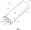
- FIG. 1 is a perspective view of one embodiment of the present invention directed to non-centerfire ammunition 100.
- the ammunition includes a cartridge 102 having a non-centerfire propellant assembly 104 and a cylindrically-shaped casing 106 retaining a projectile (not shown) thereto and/or therein.
- the casing 106 includes a case head 108 proximate a first end 110 of the cartridge 100 and the casing 106, and a hull 112 or hull body proximate a second end 114 of the cartridge 100 and the casing 106.
- the case head 108 and hull 112 of the casing 106 may be constructed of a unitary piece of material, for example, aluminum, that has been machined, formed, stamped, and/or drawn to form the casing 106.
- the casing 106, case head 108, and/or hull 112 may also be formed or generated using a 3D printer.
- the case head 108 and hull 112 may be contiguous pieces of similar or different material and integrated to each other.
- the case head 108 may be a metal or metal alloy and the hull 112 may be plastic, paper, polymer, and the like, and vice-versa.
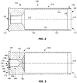
- FIG. 2 is a cross-sectional illustration of one embodiment of the casing 106 shown in FIG. 1 .
- the casing 106 encompasses an interior 116 and includes a longitudinal axis 118 extending through the first 110 and second 114 ends of the casing 106.
- the first 110 and second 114 ends of the casing 106 lie within respective planes that are substantially perpendicular to the longitudinal axis 118 of the casing 106.
- the hull 112 of the casing 106 includes a circumference or wall 120 having an exterior surface 122 and an interior surface 124.
- the thickness of the casing 106 for example, near the wall 120 of the hull 112, is substantially equal to the distance between the interior 124 and exterior 122 surfaces of the casing 106.
- the thickness of the wall 120 is substantially equal to an outer diameter of a portion of the casing 106 minus an interior diameter of the corresponding portion of the casing 106.
- the thickness of the wall 120 may taper 126 near the second 114 end of the casing 106 to facilitate crimping or deforming the casing 106 proximate the second end 114 of the casing 106 to fully or partially enclose the interior 116 of the hull 112.
- Portions of the hull 112 proximate the second end 114 of the casing 106 may also include means for affixing 128 the projectile (not shown) to and/or within the hull 112 proximate the second end 114 of the casing 106.
- Examples of the means for affixing 128 the projectile to and/or within the hull 112 include, and are not limited to, seams, creases, tapering, and a like within the wall 120 of the casing 106 to facilitate manipulating, folding, or bending, the wall 120, as well as a plug, disc, and/or rolled edge to retain the projectile to and/or within the hull 112.
- At least a portion of the case head 108 includes an opening 130 centrally located within the case head 108 proximate the first end 110 of the casing 106.
- the opening 130 is shown as circular and coaxially aligned with the longitudinal axis 118 of the casing 106.
- At least a portion of the non-centerfire propellant assembly (not shown) is disposed within the opening 130 and retained therein.
- FIG. 3 is a cross-section illustration of the casing shown in FIG. 2 with one embodiment of the non-centerfire propellant assembly 104 disposed therein.
- the non-centerfire propellant assembly 104 includes a non-centerfire primer assembly 150 disposed within the opening 130 and proximate a propellant charge 152 or powder charge.
- the non-centerfire primer assembly 150 and the propellant charge 152 of the non-centerfire propellant assembly 104 are combined or located sufficiently near each other so that ignition of the non-centerfire primer assembly 150 will ignite the propellant charge 152.
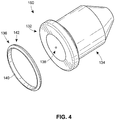
- FIG. 4 illustrates one embodiment of the non-centerfire primer assembly 150 positioned within the opening 130 shown in FIG. 3 .
- the non-centerfire primer assembly 150 which may at times be referred to as a power cartridge, includes a base 132 and a cap 134.
- the power cartridge is illustrated as a one piece, drawn steel case.
- the base 132 of the non-centerfire primer assembly 150 includes an annulus incendiary portion 136 surrounding an inert portion 138.
- the annulus incendiary portion136 includes a priming or primer compound 140 disposed about a perimeter or rim 142 of the base 132.
- FIG. 5 is a cross-section illustration of the non-centerfire primer assembly 150 shown in FIG. 4 .
- the rim 142 of the non-centerfire primer assembly150 may include a fold, channel, or groove, wherein the primer compound 140 is encapsulated and substantially confined within the rim 142 of the base 132.
- the inert portion 138 which is centrally located within the base 132, is absent the primer compound.
- a means for coupling 144 the non-centerfire primer assembly 150 may include a recess 129 within the case head 108 and surrounding the opening 130.
- the rim 142 of the base 132 of the non-centerfire primer assembly 150 may include a footing or shoulder that abuts the recess 129 to align the base 132 of the non-centerfire primer assembly 150 within substantially the same plane as the first end 110 of the casing 106. That is, the base 132 of the non-centerfire primer assembly 150 and the first end 110 of the casing 106 are substantially coplanar.
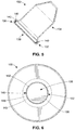
- FIG. 6 is an illustration of the first end 110 of the cartridge 100 as viewed along the longitudinal axis 118 of the casing 106 and illustrates the non-centerfire primer assembly 150 positioned within the opening 130 of the case head 108.
- the first end 110 of the casing 106 may include a means for facilitating ignition 146 of the primer compound 140 within the rim 142 of the base 132 of the non-centerfire primer assembly 150.
- the means for facilitating ignition 146 may include a space 148 for the annulus incendiary portion 136 of the base 132 to deform in response to the firing pin or hammer of the firing device striking or impacting the rim 142 of the base 132. As shown in FIG.
- the space 148 provides an area into which the fold, channel, or groove of the rim 142 may deform.
- the rim 142 may be pinched or squeezed and collapse upon the incendiary portion 136 and ignite the primer compound 140.
- the inert region 138 of the base 132 is centrally located within the case head 108 and proximate the longitudinal axis 118 of the casing 106 is absent the primer compound. As such, the striking of the firing pin to this inert region 138 of the base 132 will not ignite the primer compound 140 of the non-centerfire primer assembly 150, and thus the powder compound 152 will not be ignited.
- FIG. 7 is a cross-sectional illustration of the cartridge 100 illustrated in FIG. 1 .
- the cartridge 100 incorporates the non-centerfire propellant assembly 104, which includes the non-centerfire primer assembly 150 disposed within the opening 130 of the case head 108 and proximate the propellant or powder charge 152 within the casing 106. Retention of the non-centerfire primer assembly 150 within the opening 130 of the case head 108 may be by friction fit or any other known method relating to retaining a primer within a cartridge.
- the propellant or powder charge 152 is located within or sufficiently near the non-centerfire primer assembly 150 such that ignition of the primer compound 140 will then ignite the propellant charge 152.
- the propellant charge includes another explosive material that will ignite in response to the ignition of the primer compound of the annulus incendiary portion of the non-centerfire primer assembly being struck by the firing pin and alike of the firing device. Ignition of the propellant charge creates gases that increase in pressure and the projectile 156 will eventually be dislodged from the casing and expelled from the firing device.
- a seal 154 is proximate the propellant charge 152 and provides a gas seal to prevent the propellant charge 152 from mixing with the projectile 156 and blowing through the projectile 156 rather than propelling the projectile 156 from the casing 106 after the cartridge 100 has been fired.
- the seal 154 may include a wad or protective cup for containing the projectile 156 until the projectile 156 exits the firing device.
- the second end 114 of the casing 106 includes a means for affixing 128 the projectile 156 to and/or within the casing 106.
- the means for affixing 128 may include structural features of the casing 106 near the hull 112 such as the tapered wall 126 or a preformed crease 191 proximate the second end 114 of the casing 106, and/or an inherit pliability associated with the malleableness of the material composition of the casing 106 to facilitate shaping the casing 106 about its second end 114.
- the folded, rolled, or crimped portion of the hull 112 may extend toward the longitudinal axis 118 of the casing 106 to retain the projectile 156 within the hull 112 and/or affix the projectile 156 to the casing 106 until the cartridge 100 is fired.
- the means for affixing 128 the projectile to and/or within the casing 106 may include a stop such as a disc or plate 158 inserted or attached proximate the second end 114 of the casing 106.
- FIG. 8 is an exploded view of the cartridge 100 shown in FIG. 7 .
- the cartridge 100 includes the annulus incendiary portion 136 positioned about the rim 142 of the non-centerfire primer assembly 150.
- the non-centerfire primer assembly 150 resides within the case head 108 and is positioned near the propellant charge 152.
- the seal 154 resides between the propellant charge 152 and the projectile 156.
- the second end 114 of the casing 106 includes the disc 158 as part of the means for affixing 128 the projectile within and/or to the casing 106.
- FIG. 9 is an exploded view of an alternate embodiment of the cartridge 100 described herein.
- the non-centerfire primer assembly 150 which includes the annulus incendiary portion 136 positioned about the rim 142, resides within the case head 108 near the propellant charge 152.
- a base wad 153 resides with the hull body 112 between the non-centerfire primer assembly 150 and the propellant charge152.
- the seal 154 or fiber disc is positioned between the propellant charge 152 and the projectile 156.
- a paper disc 158 may be included within the means for retaining the projectile within the hull 112 of the casing 106 until the cartridge 100 is fired by the firing device.
- the explosive components of the non-centerfire propellant assembly 104 may be of a type and amount appropriate for a lethal or a non-lethal purpose.
- the design and material composition of the projectile 156 may be based on its intended use.
- the projectile 156 may be comprised primarily of metal.
- the projectile 156 may include a non-metal material, for example, polymer, rubber; of varying shapes and sizes, for example, spheres, bean bag.
- the casing 106 may include an indicator such as a shape or description denoting the intended application for the cartridge 100.
- lethal or less-lethal applications for the cartridge 100 may be distinguished by the exterior surface of the casing 106, which may include a visible and/or tangible identifier such as a color, symbol, and/or a textured pattern, for example, a multi-sided geometric shape such as an octagonal-shaped circumference, stripes, and/or tactile cross-hatching.
- a visible and/or tangible identifier such as a color, symbol, and/or a textured pattern
- a multi-sided geometric shape such as an octagonal-shaped circumference, stripes, and/or tactile cross-hatching.
- the non-centerfire propellant assembly 204 includes the non-centerfire primer assembly 250 that is similar and/or identical to the non-centerfire primer assembly 150 described above in FIGS. 4 and 5 .
- the non-centerfire primer assembly 250 is operatively attached to a propellant charge casing 160 that contains the propellant or powder charge therein.
- the non-centerfire primer assembly 250 is seated and inserted within an opening 182 in the end of the propellant charge casing 160 to form the non-centerfire propellant assembly 204.
- the assembly of the non-centerfire primer assembly 250 within the propellant charge casing 160 may be similar to that described in relation to the non-centerfire-primer assembly 150 disposed within the opening 230 of the case head 208 of the casing 106 in FIGS. 3 and 6 . That is, the non-centerfire primer assembly 250 may be retained within the powder charge case 160 by an interference fit or any other known manner related to retaining a primer within a casing. Similarly, the non-centerfire propellant assembly 204 may be retained within the opening 230 of the case head 208 in a similar manner.
- the opening 182 within the end of the propellant charge case 160 may include a means for facilitating ignition of the primer compound within the rim of the base of the non-centerfire primer assembly 250.
- the means for facilitating ignition may include a space for the annulus incendiary portion of the base to deform in response to the firing pin or hammer of the firing device striking or impacting the rim of the base.
- the space provides an area into which the fold, channel, or groove of the rim may deform.
- the rim may be pinched or squeezed and collapse upon the incendiary portion and ignite the primer compound.
- the inert region of the base is centrally located within the case head and proximate the longitudinal axis of the cartridge casing is absent the primer compound.
- the striking of the firing pin to the inert region of the base will not ignite the primer compound of the non-centerfire primer assembly 250, and thus the powder compound within the propellant charge case 160 will not be ignited.
- the non-centerfire propellant assembly 204 is disposed within the opening 230 of the case head 208 and adjacent an expansion chamber (not shown) within the case head and/or hull body of the cartridge casing.
- gas pressure will increase within the powder charge casing 160 and ultimately explode into the expansion chamber (not shown) to dislodge the projectile from the cartridge casing.
- the non-centerfire propellant assembly 204 shown in FIG. 10 may be integrated with larger cartridges employing a 37mm or 40mm casing. Some examples of the larger cartridges are illustrated in FIGS. 11 and 12. FIG. 11 depicts a 40mm cartridge with one type of projectile 256 attached to and extending beyond its casing 206 and FIG. 12 depicts a 40mm cartridge with another type of projectile 356 attached to and extending beyond its casing 306. It is to be understood that although the non-centerfire propellant assembly 204 are implemented with cartridges wherein the projectile 256, 356 extends beyond the casing 206, 306, the non-centerfire propellant assembly 204 is also capable of being implement with a cartridge wherein the projectile is housed entirely or partially within the cartridge casing.
- FIG. 13 is a cross-sectional view of the 40mm cartridge shown in FIG. 12 .
- the non-centerfire propellant assembly 204 is disposed within the case head 208, wherein the expansion chamber 162 is proximate the propellant charge case 160 of the non-centerfire propellant assembly 204 and the projectile 356.
- Various interior designs may be incorporated within the case head 208 to receive the non-centerfire propellant assembly 204.
- various designs of the expansion chamber 162 may be defined by the interior of the case head 208, hull, and/or the projectile 356.
- FIG. 14 depicts an offset firing pin assembly 164 for a non-centerfire firing device capable of firing larger caliber cartridges and shotshells having the non-centerfire primer assembly described herein; for example, .50 caliber, pump action shotgun, semi-automatic shotgun, riot gun (37mm, 40mm), less-lethal launcher, paintball gun.
- the offset firing pin assembly 164 includes a striker 190, for example, firing pin; and a bolt 192, wherein the firing pin 190 is longitudinally positioned through the bolt 192.
- the firing assembly may also include a bolt carrier 194 capable of being operatively coupled to the bolt 192.
- the firing assembly 164 is configured to align the firing pin 190 to strike the non-centerfire primer assembly of the non-centerfire cartridge in response to the actuation of a trigger assembly (not shown) operatively coupled to the offset firing pin assembly 164.
- the offset firing pin assembly 164 may be configured to cooperate with the receiver assembly, trigger assembly, and barrel of the firing device to align the firing pin 190 for contact with the non-centerfire primer assembly of the non-centerfire propellant assembly of the loaded non-centerfire cartridge.
- FIG. 15 is an illustration of an alternate embodiment of the offset firing pin assembly shown in FIG. 14 and designed to transfer the force generated by a trigger assembly of the firing device directed to the center of a cartridge to the incendiary portion of the non-centerfire primer assembly described herein.
- the offset firing pin assembly 264 includes an offset retainer 266.
- a firing pin 268, a firing pin spring (not shown), and a firing pin retainer (not shown) are configured with the offset retainer 266 for translating the force exhibited by a striker or hammer of a conventional centerfire firing device to the non-centerfire primer assembly of the non-centerfire cartridge described herein.
- the offset retainer 266 may be considered a bolt having a generally cylindrical shape and including a longitudinal axis 274 there through.
- the firing pin 268 is retained within an opening (not shown) that extends between a first end 278 and a second end 280 of the offset retainer 266.
- the first end 278 of the offset retainer 266 is proximate the striker or hammer of the firing device for operative cooperation therewith, and the second end 280 of the offset retainer 266 is proximate the non-centerfire cartridge 100 when in battery and ready for firing from the firearm.
- FIG. 16 is cross-sectional view of the offset firing pin assembly shown in FIG. 15 .
- the offset firing pin assembly includes an offset retainer 266 having a longitudinal axis there through (see 274 in FIG. 15 ).
- An opening 276 extends through the offset retainer 266 from the first end 278 of the offset retainer 260 to the second end of the offset retainer 266.
- the firing pin 268, a firing pin spring 270, and a firing pin retainer 272 are operatively configured within the opening 274 of the offset retainer 266 to translate the force received by a striker or hammer of a conventional centerfire firing device at the firing pin 268 at the first end 278 of the offset retainer 266 to the annulus incendiary portion of the non-centerfire primer assembly of the non-centerfire cartridge.
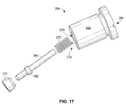
- FIG. 17 is an exploded view of the offset firing pin assembly 264 shown in FIG. 15 and including the offset retainer 266, the firing pin 268, the firing pin spring 270, and the firing pin retainer 272.
- the firing pin 268 may include a collar 282 radially extending from the firing pin 268.
- the collar 282 may be integral to the firing pin 268 or affixed thereto.
- the firing pin 268 is positioned within the firing pin spring 270 and within the opening 276 of the offset retainer 266.
- the firing pin retainer 272 may be ring-shaped and slid onto the firing pin 268.
- the firing pin retainer 272 cooperates with the interior of the opening 276 of the offset retainer 266 to secure the firing pin 268 within the opening 276.
- the firing pin retainer 272 may be keyed or threaded to cooperate with the offset retainer 266 and/or the firing pin 268.
- the firing pin spring 270 cooperates with the opening 276 and the collar 282 to position the firing pin 268 as desired. When the offset firing pin assembly is assembled and at rest, the forces of the firing pin spring 270 pushes the collar 282 of the firing pin 268 toward the first end 278 or striking end of the offset retainer 266.
- the portion of the firing pin 268 extending from the second side 280 or cartridge side of the offset retainer 266 is positioned so as not to interact with the non-centerfire primer assembly of a cartridge in battery until the firing pin 268 is struck by the trigger assembly of the firing device. That is, when the firing device is activated to fire the cartridge, the striker or hammer of the firing device will contact the centrally locator firing pin 268 at the first end of the offset retainer 266 with sufficient force to compress the firing pin spring 270 via the collar 282 such that the firing pin 268 will move toward the second end 280 of the offset retainer 266 and the cartridge in battery to deform the incendiary portion of the non-centerfire primer assembly.
- FIG 18 is a flow diagram of an example method for assembling one embodiment of the non-centerfire cartridge of the present invention.
- Each component of the non-centerfire cartridge may be manufactured separately by any known means of manufacturing ammunition components and the like and then assembled into the cartridge using any known means of manufacturing ammunition and the like.
- the method 500 includes providing a cartridge having a casing (block 502).
- a non-centerfire propellant assembly is adapted to the casing (block 504).
- the non-centerfire propellant assembly may be partially and/or fully constructed before, during, or after being affixed to the casing.
- the non-centerfire primer assembly and propellant charge may be separately inserted into the casing and positioned near each other.
- the non-centerfire primer assembly may be inserted into the casing powder charge to form the non-centerfire propellant assembly, which may then be inserted into the case head.
- the powder charge case may first be inserted into the case head and then the non-centerfire primer assembly can be inserted within the powder charge case.
- the case head and hull body of the cartridge may be attached together before, during, or after any point during the construction of the non-centerfire primer assembly.
- the powder charge may be of a type and amount sufficient for lethal or less-lethal purposes.
- a lethal or less-lethal projectile is attached to enclosed within the casing (block 506).
- FIG. 19 is a flow diagram of an example method for translating a force received from a centerfire firing device to a cartridge including a non-centerfire propellant assembly.
- the method 700 includes an offset firing pin assembly receiving an impact from a centerfire trigger assembly (block 702).
- the offset firing pin assembly includes an offset retainer having a first end and a second end, and an opening that extends through the offset retainer to the first and second ends.
- the firing pin is disposed within the opening and capable of extending beyond the first and second ends of the offset retainer, wherein in response to the firing pin receiving an impact force by the trigger assembly, the firing pin is configured to transfer the received force to impact the non-centerfire cartridge when loaded in battery position and in response to actuation of the trigger assembly.
- the offset firing pin assembly receives a force intended and or directed to be applied along the longitudinal axis of the loaded cartridge and translates the axial force to impact the cartridge off its longitudinal axis and onto the non-centerfire primer assembly that is coaxially positioned about the longitudinal axis.
- FIG. 20 is a flow diagram of an example method for converting a centerfire firing device to a non-centerfire firing device using an offset firing pin assembly.
- the method 600 includes removing the centerfire firing pin assembly from the firing device (block 602).
- An offset (non-centerfire) fire pin assembly is then stalled within the firing device in place of the centerfire firing pin assembly (block 604).
- the offset retainer includes a first end, a second end, and an opening extending through the offset retainer to the first and second ends.
- the firing pin is disposed within the opening and capable of extending beyond the first and second ends of the offset retainer, wherein in response to the firing pin receiving an impact force by the trigger assembly, the firing pin is configured to transfer the received force to impact the non-centerfire cartridge when loaded in battery position and in response to actuation of the trigger assembly.
- the non-centerfire primer assembly for example, the annulus incendiary portion, includes a primer compound surrounding an inert portion that is absent the primer compound and/or any other type of incendiary matter.
- the non-centerfire primer assembly is absent any structure that is capable of facilitating an explosion of the primer compound and further igniting the propellant or powder charge in response to an impact received from a striker of a firing device near the center of the base of the cartridge casing.
- the non-centerfire primer assembly is absent any structure that is capable of facilitating an explosion of the primer compound and further igniting the propellant or powder charge in response to an impact received from a striker of a firing device near the perimeter of the base of cartridge casing.
- a lethal cartridge implementing a rimfire or centerfire primer is incapable of being fired from a less-lethal firing device implementing the offset firing pin assembly described herein.
- a cartridge implementing the non-centerfire primer assembly of the present invention is not able to be fired from a conventional firing device with a conventional centerfire or rimfire firing mechanism.
- the size of the cartridge and/or firing assembly described herein is dependent upon the manufacturer.
- the cartridge and/or bolt-carrier assembly may be sized for use with any standard cartridge size, type (e.g., bullet, shotshell, canister), and/or gauge, e.g., 10 ga, 12 ga, 20 ga, 28 ga, high brass and/or low brass loads.
- the projectile of the cartridge may be of any size and/or type, e.g., less lethal non-metal shot and/or slugs, bean bags.
- any reference to "one embodiment” or “an embodiment” means that a particular element, feature, structure, or characteristic described in connection with the embodiment is included in at least one embodiment.
- the appearances of the phrase “in one embodiment” in various places in the specification are not necessarily all referring to the same embodiment.
- operatively coupled and “operatively connected” along with their derivatives.
- some embodiments may be described using the term “operatively coupled” to indicate that two or more elements are in direct physical contact.
- operatively coupled may also mean that two or more elements are not in direct contact with each other, but yet still cooperate or interact with each other in an operative manner.
- the embodiments are not limited in this context.
- the terms “comprises,” “comprising,” “includes,” “including,” “has,” “having” or any other variation thereof, are intended to cover a non-exclusive inclusion.
- a process, method, article, or apparatus that comprises a list of elements is not necessarily limited to only those elements but may include other elements not expressly listed or inherent to such process, method, article, or apparatus.
- “or” refers to an inclusive or and not to an exclusive or. For example, a condition A or B is satisfied by any one of the following: A is true (or present) and B is false (or not present), A is false (or not present) and B is true (or present), and both A and B are true (or present).
Description
- The invention relates generally to the field of munitions, and more specifically to a less-lethal cartridge.
- Conventional munitions for small arms, i.e., revolvers, pistols, rifles; and light weapons, i.e., hand-held grenade launchers, recoilless rifles; typically utilize a cartridge with a rimfire or centerfire primer. When the hammer or firing pin of the mechanical firing device, for example, a firearm, impacts the priming or primer compound, the primer compound explodes to ignite the propellant charge within the cartridge and the projectile is expelled from the cartridge casing.
- Generally speaking, a conventional firearm may be used with lethal or less-lethal cartridges. Munitions are available in different calibers, gauges, and loads for a variety of purposes. Military, police, and security forces typically employ lethal and less-lethal cartridges for self-defense, refugee control, crowd control, riot control, and prisoner control. Lethal cartridges are intended to cause grave bodily injury and even death to a living target. Less-lethal cartridges are intended to be less likely to significantly wound or kill a living target and although a severe casualty or death may result whenever lethal or less-lethal force is applied, a less-lethal cartridge is intended to minimize that risk.
- A conventional firearm with a less-lethal cartridge may be referred to as a non-lethal weapon, less-lethal weapon, a less-than-lethal weapon, a non-deadly weapon, a compliance weapon, riot gun, less-lethal launcher, or a pain-inducing weapon. Much of the construction of the customary less-lethal cartridge, such as the size of the cartridge and the use of a centerfire primer, is essentially identical to the conventional lethal cartridge except that the less-lethal cartridge includes less powder charge, and/or the projectile of the less-lethal cartridge is made of a low-density material, such as rubber. Such a cartridge can be found in
WO2010/085734A1 . Because the less-lethal and lethal cartridges are similarly constructed, both types of cartridges are compatible with a conventional firearm. While this interchangeability is at times beneficial, it also poses a danger to a user who unknowingly loads a lethal cartridge into the conventional firearm for response to a less-lethal situation. In addition, if law enforcement personnel were to lose possession or control of the conventional firearm being used with less-lethal ammunition as a less-lethal weapon in a less-lethal situation, the conventional firearm may readily be used by an unwanted user with lethal cartridges as a lethal weapon. A need therefore exists for a less-lethal cartridge and a compatible less-lethal firearm, wherein conventional lethal cartridges are not able to be readily used with the less-lethal firearm. - The present invention is directed to less-lethal ammunition and use of a compatible less-lethal mechanical firing device, wherein a conventional lethal cartridge is not able to be fired from the less-lethal firing device. More particularly, the present invention includes a non-centerfire less-lethal cartridge. Consequently, a non-centerfire firearm is able to fire a less-lethal non-centerfire cartridge, but is not able to fire a conventional lethal cartridge having a rimfire or centerfire primer.
- The present invention is directed to a less-lethal shotgun/shotshell, 37mm, or 40mm cartridge according to claim 1 and the corresponding method of manufacturing the cartridge according to claim 9.
- The figures described below depict various aspects of the devices, systems, and methods disclosed herein. It should be understood that each figure depicts an embodiment of a particular aspect of the disclosed system and methods, and that each of the figures is intended to accord with a possible embodiment thereof. Further, wherever possible, the following description refers to the reference numerals included in the following figures, in which features depicted in multiple figures are designated with consistent reference numerals.
-
FIG. 1 is a perspective view of one embodiment of a non-centerfire cartridge of the present invention as described herein. -
FIG. 2 is a cross-section view of the casing of the non-centerfire cartridge shown inFIG. 1 . -
FIG. 3 is a cross-section view illustrating one embodiment of a non-centerfire propellant assembly implemented within the casing shown inFIG. 2 . -
FIG. 4 is an exploded view of one embodiment of a non-centerfire primer assembly described herein. -
FIG. 5 is a cross-section view of the non-centerfire primer assembly shown inFIG. 4 -
FIG. 6 is a view of one embodiment of the case head of the casing along the longitudinal axis of the cartridge shown inFIG. 1 -
FIG. 7 is a cross-section view of the non-centerfire cartridge shown inFIG. 1 . -
FIG. 8 is an exploded view the non-centerfire cartridge shown inFIG 1 . -
FIG. 9 is an exploded view of an alternate embodiment of the non-centerfire cartridge of the present invention described herein. -
FIG. 10 is an exploded view of an embodiment of the non-centerfire propellant assembly of the present invention as described herein. -
FIG. 11 is an illustration of an alternate embodiment of a non-centerfire cartridge not forming part of the invention. -
FIG. 12 is an illustration of an alternate embodiment of a non-centerfire cartridge not forming part of the invention. -
FIG. 13 is an cross-section view of the non-centerfire cartridge shown inFIG. 12 . -
FIG. 14 is an exploded view of an embodiment of an offset firing pin assembly. -
FIG. 15 is an illustration of another embodiment of an offset firing pin assembly. -
FIG. 16 is a cross-section view of the offset firing pin assembly shown inFIG. 15 . -
FIG. 17 is an exploded view of the offset firing pin assembly shown inFIG. 15 . -
FIG. 18 is an example method for assembling a cartridge with the non-centerfire propellant assembly of the present invention as described herein. -
FIG. 19 is an example method of converting a centerfire firing device to a non-centerfire firing device using the offset firing pin assembly. -
FIG. 20 is an example method for converting a centerfire firing device to a non-centerfire firing device using the offset firing pin assembly. -
FIG. 1 is a perspective view of one embodiment of the present invention directed to non-centerfireammunition 100. The ammunition includes acartridge 102 having anon-centerfire propellant assembly 104 and a cylindrically-shaped casing 106 retaining a projectile (not shown) thereto and/or therein. Thecasing 106 includes acase head 108 proximate afirst end 110 of thecartridge 100 and thecasing 106, and ahull 112 or hull body proximate asecond end 114 of thecartridge 100 and thecasing 106. Thecase head 108 andhull 112 of thecasing 106 may be constructed of a unitary piece of material, for example, aluminum, that has been machined, formed, stamped, and/or drawn to form thecasing 106. Thecasing 106,case head 108, and/orhull 112 may also be formed or generated using a 3D printer. Alternatively, thecase head 108 andhull 112 may be contiguous pieces of similar or different material and integrated to each other. For example, thecase head 108 may be a metal or metal alloy and thehull 112 may be plastic, paper, polymer, and the like, and vice-versa. -
FIG. 2 is a cross-sectional illustration of one embodiment of thecasing 106 shown inFIG. 1 . Thecasing 106 encompasses aninterior 116 and includes alongitudinal axis 118 extending through the first 110 and second 114 ends of thecasing 106. The first 110 and second 114 ends of thecasing 106 lie within respective planes that are substantially perpendicular to thelongitudinal axis 118 of thecasing 106. In general, thehull 112 of thecasing 106 includes a circumference orwall 120 having anexterior surface 122 and aninterior surface 124. The thickness of thecasing 106, for example, near thewall 120 of thehull 112, is substantially equal to the distance between theinterior 124 and exterior 122 surfaces of thecasing 106. In other words, the thickness of thewall 120 is substantially equal to an outer diameter of a portion of thecasing 106 minus an interior diameter of the corresponding portion of thecasing 106. The thickness of thewall 120 may taper 126 near the second 114 end of thecasing 106 to facilitate crimping or deforming thecasing 106 proximate thesecond end 114 of thecasing 106 to fully or partially enclose theinterior 116 of thehull 112. Portions of thehull 112 proximate thesecond end 114 of thecasing 106 may also include means for affixing 128 the projectile (not shown) to and/or within thehull 112 proximate thesecond end 114 of thecasing 106. Examples of the means for affixing 128 the projectile to and/or within thehull 112 include, and are not limited to, seams, creases, tapering, and a like within thewall 120 of thecasing 106 to facilitate manipulating, folding, or bending, thewall 120, as well as a plug, disc, and/or rolled edge to retain the projectile to and/or within thehull 112. - At least a portion of the
case head 108 includes an opening 130 centrally located within thecase head 108 proximate thefirst end 110 of thecasing 106. Theopening 130 is shown as circular and coaxially aligned with thelongitudinal axis 118 of thecasing 106. At least a portion of the non-centerfire propellant assembly (not shown) is disposed within theopening 130 and retained therein. -
FIG. 3 is a cross-section illustration of the casing shown inFIG. 2 with one embodiment of thenon-centerfire propellant assembly 104 disposed therein. Thenon-centerfire propellant assembly 104 includes anon-centerfire primer assembly 150 disposed within theopening 130 and proximate apropellant charge 152 or powder charge. Thenon-centerfire primer assembly 150 and thepropellant charge 152 of thenon-centerfire propellant assembly 104 are combined or located sufficiently near each other so that ignition of thenon-centerfire primer assembly 150 will ignite thepropellant charge 152. -
FIG. 4 illustrates one embodiment of thenon-centerfire primer assembly 150 positioned within theopening 130 shown inFIG. 3 . Thenon-centerfire primer assembly 150, which may at times be referred to as a power cartridge, includes abase 132 and acap 134. The power cartridge is illustrated as a one piece, drawn steel case. Thebase 132 of thenon-centerfire primer assembly 150 includes an annulusincendiary portion 136 surrounding aninert portion 138. The annulus incendiary portion136 includes a priming orprimer compound 140 disposed about a perimeter or rim 142 of thebase 132. -
FIG. 5 is a cross-section illustration of thenon-centerfire primer assembly 150 shown inFIG. 4 . Therim 142 of the non-centerfire primer assembly150 may include a fold, channel, or groove, wherein theprimer compound 140 is encapsulated and substantially confined within therim 142 of thebase 132. Theinert portion 138, which is centrally located within thebase 132, is absent the primer compound. - Referring again to
FIG. 3 , when thenon-centerfire primer assembly 150 is integrated within theopening 130 of thecase head 108, the annulusincendiary portion 136 including theprimer compound 140 and therim 142 of thenon-centerfire primer assembly 150 are coaxially aligned with thecasing 106 along thelongitudinal axis 118 of thecasing 106. To facilitate operative placement and retention of thenon-centerfire primer assembly 150 within thecase head 108 of thecasing 106, a means for coupling 144 thenon-centerfire primer assembly 150 may include arecess 129 within thecase head 108 and surrounding theopening 130. Therim 142 of thebase 132 of thenon-centerfire primer assembly 150 may include a footing or shoulder that abuts therecess 129 to align thebase 132 of thenon-centerfire primer assembly 150 within substantially the same plane as thefirst end 110 of thecasing 106. That is, thebase 132 of thenon-centerfire primer assembly 150 and thefirst end 110 of thecasing 106 are substantially coplanar. -
FIG. 6 is an illustration of thefirst end 110 of thecartridge 100 as viewed along thelongitudinal axis 118 of thecasing 106 and illustrates thenon-centerfire primer assembly 150 positioned within theopening 130 of thecase head 108. Thefirst end 110 of thecasing 106 may include a means for facilitatingignition 146 of theprimer compound 140 within therim 142 of thebase 132 of thenon-centerfire primer assembly 150. The means for facilitatingignition 146 may include aspace 148 for the annulusincendiary portion 136 of the base 132 to deform in response to the firing pin or hammer of the firing device striking or impacting therim 142 of thebase 132. As shown inFIG. 6 , thespace 148 provides an area into which the fold, channel, or groove of therim 142 may deform. For example, in response to being struck by the firing pin of the firearm, therim 142 may be pinched or squeezed and collapse upon theincendiary portion 136 and ignite theprimer compound 140. In contrast, theinert region 138 of thebase 132 is centrally located within thecase head 108 and proximate thelongitudinal axis 118 of thecasing 106 is absent the primer compound. As such, the striking of the firing pin to thisinert region 138 of the base 132 will not ignite theprimer compound 140 of thenon-centerfire primer assembly 150, and thus thepowder compound 152 will not be ignited. -
FIG. 7 is a cross-sectional illustration of thecartridge 100 illustrated inFIG. 1 . Thecartridge 100 incorporates thenon-centerfire propellant assembly 104, which includes thenon-centerfire primer assembly 150 disposed within theopening 130 of thecase head 108 and proximate the propellant orpowder charge 152 within thecasing 106. Retention of thenon-centerfire primer assembly 150 within theopening 130 of thecase head 108 may be by friction fit or any other known method relating to retaining a primer within a cartridge. The propellant orpowder charge 152 is located within or sufficiently near thenon-centerfire primer assembly 150 such that ignition of theprimer compound 140 will then ignite thepropellant charge 152. The propellant charge includes another explosive material that will ignite in response to the ignition of the primer compound of the annulus incendiary portion of the non-centerfire primer assembly being struck by the firing pin and alike of the firing device. Ignition of the propellant charge creates gases that increase in pressure and the projectile 156 will eventually be dislodged from the casing and expelled from the firing device. Aseal 154 is proximate thepropellant charge 152 and provides a gas seal to prevent thepropellant charge 152 from mixing with the projectile 156 and blowing through the projectile 156 rather than propelling the projectile 156 from thecasing 106 after thecartridge 100 has been fired. Theseal 154 may include a wad or protective cup for containing the projectile 156 until the projectile 156 exits the firing device. - The
second end 114 of thecasing 106 includes a means for affixing 128 the projectile 156 to and/or within thecasing 106. The means for affixing 128 may include structural features of thecasing 106 near thehull 112 such as thetapered wall 126 or apreformed crease 191 proximate thesecond end 114 of thecasing 106, and/or an inherit pliability associated with the malleableness of the material composition of thecasing 106 to facilitate shaping thecasing 106 about itssecond end 114. When shaped, the folded, rolled, or crimped portion of thehull 112 may extend toward thelongitudinal axis 118 of thecasing 106 to retain the projectile 156 within thehull 112 and/or affix the projectile 156 to thecasing 106 until thecartridge 100 is fired. In addition to or in place of the taperedwall 126 and/or formability characteristics of thehull 112, the means for affixing 128 the projectile to and/or within thecasing 106 may include a stop such as a disc orplate 158 inserted or attached proximate thesecond end 114 of thecasing 106. -
FIG. 8 is an exploded view of thecartridge 100 shown inFIG. 7 . Thecartridge 100 includes the annulusincendiary portion 136 positioned about therim 142 of thenon-centerfire primer assembly 150. Thenon-centerfire primer assembly 150 resides within thecase head 108 and is positioned near thepropellant charge 152. Theseal 154 resides between thepropellant charge 152 and the projectile 156. Thesecond end 114 of thecasing 106 includes thedisc 158 as part of the means for affixing 128 the projectile within and/or to thecasing 106. -
FIG. 9 is an exploded view of an alternate embodiment of thecartridge 100 described herein. Thenon-centerfire primer assembly 150, which includes the annulusincendiary portion 136 positioned about therim 142, resides within thecase head 108 near thepropellant charge 152. Abase wad 153 resides with thehull body 112 between thenon-centerfire primer assembly 150 and the propellant charge152. Theseal 154 or fiber disc is positioned between thepropellant charge 152 and the projectile 156. Apaper disc 158 may be included within the means for retaining the projectile within thehull 112 of thecasing 106 until thecartridge 100 is fired by the firing device. - Depending on the intended use of the
cartridge 100, the explosive components of thenon-centerfire propellant assembly 104, for example, thenon-centerfire primer assembly 150 and thepropellant charge 152 may be of a type and amount appropriate for a lethal or a non-lethal purpose. In addition, the design and material composition of the projectile 156 may be based on its intended use. For lethal applications, the projectile 156 may be comprised primarily of metal. For less-lethal applications, the projectile 156 may include a non-metal material, for example, polymer, rubber; of varying shapes and sizes, for example, spheres, bean bag. Thecasing 106 may include an indicator such as a shape or description denoting the intended application for thecartridge 100. For example, lethal or less-lethal applications for thecartridge 100 may be distinguished by the exterior surface of thecasing 106, which may include a visible and/or tangible identifier such as a color, symbol, and/or a textured pattern, for example, a multi-sided geometric shape such as an octagonal-shaped circumference, stripes, and/or tactile cross-hatching. - Referring now to
FIG. 10 , an exploded view of an alternate embodiment of thenon-centerfire propellant assembly 204 is illustrated. Thenon-centerfire propellant assembly 204 includes thenon-centerfire primer assembly 250 that is similar and/or identical to thenon-centerfire primer assembly 150 described above inFIGS. 4 and5 . Thenon-centerfire primer assembly 250 is operatively attached to apropellant charge casing 160 that contains the propellant or powder charge therein. Thenon-centerfire primer assembly 250 is seated and inserted within an opening 182 in the end of the propellant charge casing 160 to form thenon-centerfire propellant assembly 204. The assembly of thenon-centerfire primer assembly 250 within thepropellant charge casing 160 may be similar to that described in relation to the non-centerfire-primer assembly 150 disposed within theopening 230 of thecase head 208 of thecasing 106 inFIGS. 3 and6 . That is, thenon-centerfire primer assembly 250 may be retained within thepowder charge case 160 by an interference fit or any other known manner related to retaining a primer within a casing. Similarly, thenon-centerfire propellant assembly 204 may be retained within theopening 230 of thecase head 208 in a similar manner. - The opening 182 within the end of the
propellant charge case 160 may include a means for facilitating ignition of the primer compound within the rim of the base of thenon-centerfire primer assembly 250. The means for facilitating ignition may include a space for the annulus incendiary portion of the base to deform in response to the firing pin or hammer of the firing device striking or impacting the rim of the base. The space provides an area into which the fold, channel, or groove of the rim may deform. For example, in response to being struck by the firing pin of the firearm, the rim may be pinched or squeezed and collapse upon the incendiary portion and ignite the primer compound. In contrast, the inert region of the base is centrally located within the case head and proximate the longitudinal axis of the cartridge casing is absent the primer compound. As such, the striking of the firing pin to the inert region of the base will not ignite the primer compound of thenon-centerfire primer assembly 250, and thus the powder compound within thepropellant charge case 160 will not be ignited. - The
non-centerfire propellant assembly 204 is disposed within theopening 230 of thecase head 208 and adjacent an expansion chamber (not shown) within the case head and/or hull body of the cartridge casing. Upon ignition of the powder charge within thepowder charge case 160, which occurs in response to ignition of the primer compound igniting as a result of the rim of thenon-centerfire primer assembly 250 being struck by the firing pin of the firing device, gas pressure will increase within thepowder charge casing 160 and ultimately explode into the expansion chamber (not shown) to dislodge the projectile from the cartridge casing. - The
non-centerfire propellant assembly 204 shown inFIG. 10 may be integrated with larger cartridges employing a 37mm or 40mm casing. Some examples of the larger cartridges are illustrated inFIGS. 11 and 12. FIG. 11 depicts a 40mm cartridge with one type ofprojectile 256 attached to and extending beyond itscasing 206 andFIG. 12 depicts a 40mm cartridge with another type ofprojectile 356 attached to and extending beyond itscasing 306. It is to be understood that although thenon-centerfire propellant assembly 204 are implemented with cartridges wherein the projectile 256, 356 extends beyond thecasing non-centerfire propellant assembly 204 is also capable of being implement with a cartridge wherein the projectile is housed entirely or partially within the cartridge casing. -
FIG. 13 is a cross-sectional view of the 40mm cartridge shown inFIG. 12 . Thenon-centerfire propellant assembly 204 is disposed within thecase head 208, wherein theexpansion chamber 162 is proximate thepropellant charge case 160 of thenon-centerfire propellant assembly 204 and the projectile 356. Various interior designs may be incorporated within thecase head 208 to receive thenon-centerfire propellant assembly 204. Similarly, various designs of theexpansion chamber 162 may be defined by the interior of thecase head 208, hull, and/or the projectile 356. -
FIG. 14 depicts an offsetfiring pin assembly 164 for a non-centerfire firing device capable of firing larger caliber cartridges and shotshells having the non-centerfire primer assembly described herein; for example, .50 caliber, pump action shotgun, semi-automatic shotgun, riot gun (37mm, 40mm), less-lethal launcher, paintball gun. The offsetfiring pin assembly 164 includes astriker 190, for example, firing pin; and abolt 192, wherein thefiring pin 190 is longitudinally positioned through thebolt 192. The firing assembly may also include abolt carrier 194 capable of being operatively coupled to thebolt 192. The firingassembly 164 is configured to align thefiring pin 190 to strike the non-centerfire primer assembly of the non-centerfire cartridge in response to the actuation of a trigger assembly (not shown) operatively coupled to the offsetfiring pin assembly 164. For example, the offsetfiring pin assembly 164 may be configured to cooperate with the receiver assembly, trigger assembly, and barrel of the firing device to align thefiring pin 190 for contact with the non-centerfire primer assembly of the non-centerfire propellant assembly of the loaded non-centerfire cartridge. -
FIG. 15 is an illustration of an alternate embodiment of the offset firing pin assembly shown inFIG. 14 and designed to transfer the force generated by a trigger assembly of the firing device directed to the center of a cartridge to the incendiary portion of the non-centerfire primer assembly described herein. The offsetfiring pin assembly 264 includes an offsetretainer 266. Afiring pin 268, a firing pin spring (not shown), and a firing pin retainer (not shown) are configured with the offsetretainer 266 for translating the force exhibited by a striker or hammer of a conventional centerfire firing device to the non-centerfire primer assembly of the non-centerfire cartridge described herein. The offsetretainer 266 may be considered a bolt having a generally cylindrical shape and including alongitudinal axis 274 there through. Thefiring pin 268 is retained within an opening (not shown) that extends between afirst end 278 and asecond end 280 of the offsetretainer 266. When the offsetfiring pin assembly 266 is implemented within a mechanical firing device, thefirst end 278 of the offsetretainer 266 is proximate the striker or hammer of the firing device for operative cooperation therewith, and thesecond end 280 of the offsetretainer 266 is proximate thenon-centerfire cartridge 100 when in battery and ready for firing from the firearm. -
FIG. 16 is cross-sectional view of the offset firing pin assembly shown inFIG. 15 . The offset firing pin assembly includes an offsetretainer 266 having a longitudinal axis there through (see 274 inFIG. 15 ). Anopening 276 extends through the offsetretainer 266 from thefirst end 278 of the offset retainer 260 to the second end of the offsetretainer 266. Thefiring pin 268, afiring pin spring 270, and afiring pin retainer 272 are operatively configured within theopening 274 of the offsetretainer 266 to translate the force received by a striker or hammer of a conventional centerfire firing device at thefiring pin 268 at thefirst end 278 of the offsetretainer 266 to the annulus incendiary portion of the non-centerfire primer assembly of the non-centerfire cartridge. -
FIG. 17 is an exploded view of the offsetfiring pin assembly 264 shown inFIG. 15 and including the offsetretainer 266, thefiring pin 268, thefiring pin spring 270, and thefiring pin retainer 272. Thefiring pin 268 may include acollar 282 radially extending from thefiring pin 268. Thecollar 282 may be integral to thefiring pin 268 or affixed thereto. When the offset firing pin assembly is assembled, thefiring pin 268 is positioned within thefiring pin spring 270 and within theopening 276 of the offsetretainer 266. Thefiring pin retainer 272 may be ring-shaped and slid onto thefiring pin 268. Thefiring pin retainer 272 cooperates with the interior of theopening 276 of the offsetretainer 266 to secure thefiring pin 268 within theopening 276. For example, thefiring pin retainer 272 may be keyed or threaded to cooperate with the offsetretainer 266 and/or thefiring pin 268. Thefiring pin spring 270 cooperates with theopening 276 and thecollar 282 to position thefiring pin 268 as desired. When the offset firing pin assembly is assembled and at rest, the forces of thefiring pin spring 270 pushes thecollar 282 of thefiring pin 268 toward thefirst end 278 or striking end of the offsetretainer 266. The portion of thefiring pin 268 extending from thesecond side 280 or cartridge side of the offsetretainer 266 is positioned so as not to interact with the non-centerfire primer assembly of a cartridge in battery until thefiring pin 268 is struck by the trigger assembly of the firing device. That is, when the firing device is activated to fire the cartridge, the striker or hammer of the firing device will contact the centrallylocator firing pin 268 at the first end of the offsetretainer 266 with sufficient force to compress thefiring pin spring 270 via thecollar 282 such that thefiring pin 268 will move toward thesecond end 280 of the offsetretainer 266 and the cartridge in battery to deform the incendiary portion of the non-centerfire primer assembly. -
FIG 18 . is a flow diagram of an example method for assembling one embodiment of the non-centerfire cartridge of the present invention. Each component of the non-centerfire cartridge may be manufactured separately by any known means of manufacturing ammunition components and the like and then assembled into the cartridge using any known means of manufacturing ammunition and the like. Themethod 500 includes providing a cartridge having a casing (block 502). A non-centerfire propellant assembly is adapted to the casing (block 504). The non-centerfire propellant assembly may be partially and/or fully constructed before, during, or after being affixed to the casing. For example, the non-centerfire primer assembly and propellant charge may be separately inserted into the casing and positioned near each other. Alternatively, the non-centerfire primer assembly may be inserted into the casing powder charge to form the non-centerfire propellant assembly, which may then be inserted into the case head. Further, the powder charge case may first be inserted into the case head and then the non-centerfire primer assembly can be inserted within the powder charge case. Similarly, the case head and hull body of the cartridge may be attached together before, during, or after any point during the construction of the non-centerfire primer assembly. The powder charge may be of a type and amount sufficient for lethal or less-lethal purposes. Depending on the desired application of the cartridge, a lethal or less-lethal projectile is attached to enclosed within the casing (block 506). -
FIG. 19 is a flow diagram of an example method for translating a force received from a centerfire firing device to a cartridge including a non-centerfire propellant assembly. Themethod 700 includes an offset firing pin assembly receiving an impact from a centerfire trigger assembly (block 702). The offset firing pin assembly includes an offset retainer having a first end and a second end, and an opening that extends through the offset retainer to the first and second ends. The firing pin is disposed within the opening and capable of extending beyond the first and second ends of the offset retainer, wherein in response to the firing pin receiving an impact force by the trigger assembly, the firing pin is configured to transfer the received force to impact the non-centerfire cartridge when loaded in battery position and in response to actuation of the trigger assembly. In other words, the offset firing pin assembly receives a force intended and or directed to be applied along the longitudinal axis of the loaded cartridge and translates the axial force to impact the cartridge off its longitudinal axis and onto the non-centerfire primer assembly that is coaxially positioned about the longitudinal axis. -
FIG. 20 is a flow diagram of an example method for converting a centerfire firing device to a non-centerfire firing device using an offset firing pin assembly. Themethod 600 includes removing the centerfire firing pin assembly from the firing device (block 602). An offset (non-centerfire) fire pin assembly is then stalled within the firing device in place of the centerfire firing pin assembly (block 604). The offset retainer includes a first end, a second end, and an opening extending through the offset retainer to the first and second ends. The firing pin is disposed within the opening and capable of extending beyond the first and second ends of the offset retainer, wherein in response to the firing pin receiving an impact force by the trigger assembly, the firing pin is configured to transfer the received force to impact the non-centerfire cartridge when loaded in battery position and in response to actuation of the trigger assembly. - It can be readily observed that the non-centerfire primer assembly, for example, the annulus incendiary portion, includes a primer compound surrounding an inert portion that is absent the primer compound and/or any other type of incendiary matter. In other words, the non-centerfire primer assembly is absent any structure that is capable of facilitating an explosion of the primer compound and further igniting the propellant or powder charge in response to an impact received from a striker of a firing device near the center of the base of the cartridge casing. In addition, the non-centerfire primer assembly is absent any structure that is capable of facilitating an explosion of the primer compound and further igniting the propellant or powder charge in response to an impact received from a striker of a firing device near the perimeter of the base of cartridge casing. Therefore, a lethal cartridge implementing a rimfire or centerfire primer is incapable of being fired from a less-lethal firing device implementing the offset firing pin assembly described herein. Similarly, a cartridge implementing the non-centerfire primer assembly of the present invention is not able to be fired from a conventional firing device with a conventional centerfire or rimfire firing mechanism.
- It is to be understood that the size of the cartridge and/or firing assembly described herein is dependent upon the manufacturer. For example, the cartridge and/or bolt-carrier assembly may be sized for use with any standard cartridge size, type (e.g., bullet, shotshell, canister), and/or gauge, e.g., 10 ga, 12 ga, 20 ga, 28 ga, high brass and/or low brass loads. In addition, the projectile of the cartridge may be of any size and/or type, e.g., less lethal non-metal shot and/or slugs, bean bags.
- Throughout this specification, plural instances may implement components, operations, or structures described as a single instance. Although individual operations of one or more methods are illustrated and described as separate operations, one or more of the individual operations may be performed concurrently, and nothing requires that the operations be performed in the order illustrated. Structures and functionality presented as separate components in example configurations may be implemented as a combined structure or component. Similarly, structures and functionality presented as a single component may be implemented as separate components. These and other variations, modifications, additions, and improvements fall within the scope of the invention as defined in the appended claims.
- As used herein any reference to "one embodiment" or "an embodiment" means that a particular element, feature, structure, or characteristic described in connection with the embodiment is included in at least one embodiment. The appearances of the phrase "in one embodiment" in various places in the specification are not necessarily all referring to the same embodiment.
- Some embodiments may be described using the expression "operatively coupled" and "operatively connected" along with their derivatives. For example, some embodiments may be described using the term "operatively coupled" to indicate that two or more elements are in direct physical contact. The term "operatively coupled," however, may also mean that two or more elements are not in direct contact with each other, but yet still cooperate or interact with each other in an operative manner. The embodiments are not limited in this context.
- Additionally, some embodiments may be described using the expression "cooperative," cooperative operation" and "operative cooperation" along with their derivatives. For example, some embodiments may be described using the term "operatively cooperative" to indicate that two or more elements are coupled and cooperate in an manner to achieve an intended effect, as expected.
- As used herein, the terms "comprises," "comprising," "includes," "including," "has," "having" or any other variation thereof, are intended to cover a non-exclusive inclusion. For example, a process, method, article, or apparatus that comprises a list of elements is not necessarily limited to only those elements but may include other elements not expressly listed or inherent to such process, method, article, or apparatus. Further, unless expressly stated to the contrary, "or" refers to an inclusive or and not to an exclusive or. For example, a condition A or B is satisfied by any one of the following: A is true (or present) and B is false (or not present), A is false (or not present) and B is true (or present), and both A and B are true (or present).
- In addition, use of the "a" or "an" are employed to describe elements and components of the embodiments herein. This is done merely for convenience and to give a general sense of the description. This description, and the claims that follow, should be read to include one or at least one and the singular also includes the plural unless it is obvious that it is meant otherwise.
- Although the preceding text sets forth a detailed description of numerous different embodiments, it should be understood that the legal scope of the invention is defined by the words of the claims set forth at the end of this patent. The detailed description is to be construed as example only and does not describe every possible embodiment, as describing every possible embodiment would be impractical, if not impossible. One could implement numerous alternate embodiments, using either current technology or technology developed after the filing date of this patent, which would still fall within the scope of the claims.
Claims (11)
- A less-lethal shotgun/shotshell, 37mm, or 40mm cartridge (102) for cooperative operation in less-lethal application with a non-centerfire shotgun or 37mm or 40mm launcher having an offset firing pin assembly, the shotgun, 37mm, or 40mm cartridge comprising:a cylindrical casing (106, 206) including a metallic case head (108, 208) proximate a first end (110), a hull (112) proximate a second end (114), and an interior (116) disposed within the casing between the first end and the second end, wherein the casing includes an exterior surface including a visible and/or tangible identifier indicating less-lethal capability;a non-centerfire propellant assembly (104, 204) including a non-centerfire primer assembly (150, 250) operatively positioned near a propellant charge (152);a recess (129) defined within the metallic case head and including an opening (130) centrally located proximate the first end of the metallic case head for receiving the non-centerfire primer assembly, the non-centerfire primer assembly located within the opening and including an annulus incendiary portion (136) coaxially aligned with the casing, the annulus incendiary portion surrounding an inert portion (138) centrally located within the first end of the metallic case head, wherein the annulus incendiary portion includes a primer compound (140) and the inert portion is absent the primer compound; anda less-lethal projectile (156, 256, 356) affixed to and/or within the hull proximate the second end of the casing, wherein the propellant charge is capable of being ignited when the cartridge is loaded within the non-centerfire firearm and the annulus incendiary portion of the non-centerfire primer assembly is struck by the offset firing pin assembly;a space within the metallic case head and surrounding the annulus incendiary portion of the non-centerfire primer assembly to facilitate deforming the annulus incendiary portion of the non-centerfire primer assembly in response to the striking by offset firing pin assembly.
- The shotgun, 37mm, or 40mm cartridge of claim 1, further comprising a propellant charge case (160), wherein the propellant charge (152) is retained within the propellant charge case and the non-centerfire propellant assembly (104, 204) is disposed within the propellant charge case.
- The shotgun, 37mm, or 40mm cartridge of either claim 1 or 2, wherein the casing includes aluminum.
- The shotgun, 37mm, or 40mm cartridge of any of the previous claims,
wherein the hull is integral with and extends from the metallic case head. - The shotgun, 37mm, or 40mm cartridge of any of the previous claims,
wherein the metallic case head is attached to the hull. - The shotgun, 37mm, or 40mm cartridge of any of the previous claims,
wherein the less-lethal projectile includes a less-lethal material including non-metal, polymer, or rubber. - The shotgun, 37mm, or 40mm cartridge of any of the previous claims,
wherein the projectile extends beyond the second end of the casing. - The shotgun, 37mm, or 40mm cartridge of any of the previous claims,
wherein the identifier includes any of the following: color, symbol, and textured pattern. - A method of manufacturing a less-lethal non-centerfire shotgun, 37mm, or 40mm cartridge according to any of the previous claims, the cartridge being
for use with a shotgun or 37mm or 40mm launcher including a non-centerfire firing system, the method comprising:providing a shotgun, 37mm, or 40mm cartridge including a casing and a metallic case head (502);adapting a non-centerfire propellant assembly to the metallic case head (504);disposing a less-lethal projectile within the casing (506). - The method of claim 9, wherein adapting a non-centerfire propellant assembly includes:providing a non-centerfire priming assembly including an annular incendiary portion including a primer compound positioned about an inert portion absent the primer compound; andinserting the non-centerfire primer assembly into the metallic case head for cooperation with the shotgun or 37mm or 40mm launcher.
- The method of either of claims 9 or 10, wherein adapting a non-centerfire propellant assembly includes:providing a non-centerfire priming assembly and a propellant charge case, the non-centerfire priming assembly including an annular incendiary portion having a primer compound positioned about an inert portion absent the primer compound, and the propellant charge case including a propellant charge disposed within and an opening for receiving the non-centerfire primer assembly;inserting the non-centerfire primer assembly into the opening of the propellant charge case to form the non-centerfire propellant assembly; andinserting the non-centerfire propellant assembly into the metallic case head for cooperation with the shotgun or 37mm or 40mm launcher.
Applications Claiming Priority (2)
| Application Number | Priority Date | Filing Date | Title |
|---|---|---|---|
| US14/599,217 US9217626B1 (en) | 2015-01-16 | 2015-01-16 | Shotshell and cooperating firing system |
| US14/977,066 US9879954B2 (en) | 2015-01-16 | 2015-12-21 | Less-lethal munition and mechanical firing device |
Publications (4)
| Publication Number | Publication Date |
|---|---|
| EP3045859A2 EP3045859A2 (en) | 2016-07-20 |
| EP3045859A3 EP3045859A3 (en) | 2016-11-23 |
| EP3045859B1 EP3045859B1 (en) | 2019-04-10 |
| EP3045859B9 true EP3045859B9 (en) | 2019-11-13 |
Family
ID=55174570
Family Applications (1)
| Application Number | Title | Priority Date | Filing Date |
|---|---|---|---|
| EP16151664.6A Active EP3045859B9 (en) | 2015-01-16 | 2016-01-18 | Less-lethal munition and mechanical firing device |
Country Status (3)
| Country | Link |
|---|---|
| US (1) | US9879954B2 (en) |
| EP (1) | EP3045859B9 (en) |
| ES (1) | ES2735094T3 (en) |
Families Citing this family (76)
| Publication number | Priority date | Publication date | Assignee | Title |
|---|---|---|---|---|
| US9885551B2 (en) | 2010-11-10 | 2018-02-06 | True Velocity, Inc. | Subsonic polymeric ammunition |
| US11313654B2 (en) | 2010-11-10 | 2022-04-26 | True Velocity Ip Holdings, Llc | Polymer ammunition having a projectile made by metal injection molding |
| US11118875B1 (en) * | 2010-11-10 | 2021-09-14 | True Velocity Ip Holdings, Llc | Color coded polymer ammunition cartridge |
| US11215430B2 (en) | 2010-11-10 | 2022-01-04 | True Velocity Ip Holdings, Llc | One piece polymer ammunition cartridge having a primer insert and methods of making the same |
| US10408592B2 (en) | 2010-11-10 | 2019-09-10 | True Velocity Ip Holdings, Llc | One piece polymer ammunition cartridge having a primer insert and methods of making the same |
| US11340050B2 (en) | 2010-11-10 | 2022-05-24 | True Velocity Ip Holdings, Llc | Subsonic polymeric ammunition cartridge |
| US10041770B2 (en) | 2010-11-10 | 2018-08-07 | True Velocity, Inc. | Metal injection molded ammunition cartridge |
| US8561543B2 (en) | 2010-11-10 | 2013-10-22 | True Velocity, Inc. | Lightweight polymer ammunition cartridge casings |
| US10704877B2 (en) | 2010-11-10 | 2020-07-07 | True Velocity Ip Holdings, Llc | One piece polymer ammunition cartridge having a primer insert and methods of making the same |
| US11209252B2 (en) | 2010-11-10 | 2021-12-28 | True Velocity Ip Holdings, Llc | Subsonic polymeric ammunition with diffuser |
| US10876822B2 (en) | 2017-11-09 | 2020-12-29 | True Velocity Ip Holdings, Llc | Multi-piece polymer ammunition cartridge |
| US11231257B2 (en) | 2010-11-10 | 2022-01-25 | True Velocity Ip Holdings, Llc | Method of making a metal injection molded ammunition cartridge |
| US11293732B2 (en) | 2010-11-10 | 2022-04-05 | True Velocity Ip Holdings, Llc | Method of making polymeric subsonic ammunition |
| US10480915B2 (en) | 2010-11-10 | 2019-11-19 | True Velocity Ip Holdings, Llc | Method of making a polymeric subsonic ammunition cartridge |
| US11300393B2 (en) | 2010-11-10 | 2022-04-12 | True Velocity Ip Holdings, Llc | Polymer ammunition having a MIM primer insert |
| US10352670B2 (en) | 2010-11-10 | 2019-07-16 | True Velocity Ip Holdings, Llc | Lightweight polymer ammunition cartridge casings |
| US11047663B1 (en) | 2010-11-10 | 2021-06-29 | True Velocity Ip Holdings, Llc | Method of coding polymer ammunition cartridges |
| US11047664B2 (en) | 2010-11-10 | 2021-06-29 | True Velocity Ip Holdings, Llc | Lightweight polymer ammunition cartridge casings |
| US10704876B2 (en) | 2010-11-10 | 2020-07-07 | True Velocity Ip Holdings, Llc | One piece polymer ammunition cartridge having a primer insert and methods of making the same |
| US9857151B2 (en) * | 2013-10-21 | 2018-01-02 | General Dynamics Ordnance and Tactical Systems—Canada, Inc. | Ring fire primer |
| US9835427B2 (en) | 2016-03-09 | 2017-12-05 | True Velocity, Inc. | Two-piece primer insert for polymer ammunition |
| US10760882B1 (en) | 2017-08-08 | 2020-09-01 | True Velocity Ip Holdings, Llc | Metal injection molded ammunition cartridge |
| USD882032S1 (en) | 2018-04-20 | 2020-04-21 | True Velocity Ip Holdings, Llc | Ammunition cartridge |
| USD881323S1 (en) | 2018-04-20 | 2020-04-14 | True Velocity Ip Holdings, Llc | Ammunition cartridge |
| USD882028S1 (en) | 2018-04-20 | 2020-04-21 | True Velocity Ip Holdings, Llc | Ammunition cartridge |
| USD882020S1 (en) | 2018-04-20 | 2020-04-21 | True Velocity Ip Holdings, Llc | Ammunition cartridge |
| USD882024S1 (en) | 2018-04-20 | 2020-04-21 | True Velocity Ip Holdings, Llc | Ammunition cartridge |
| USD881326S1 (en) | 2018-04-20 | 2020-04-14 | True Velocity Ip Holdings, Llc | Ammunition cartridge |
| USD882723S1 (en) | 2018-04-20 | 2020-04-28 | True Velocity Ip Holdings, Llc | Ammunition cartridge |
| USD881328S1 (en) | 2018-04-20 | 2020-04-14 | True Velocity Ip Holdings, Llc | Ammunition cartridge |
| USD882021S1 (en) | 2018-04-20 | 2020-04-21 | True Velocity Ip Holdings, Llc | Ammunition cartridge |
| USD881324S1 (en) | 2018-04-20 | 2020-04-14 | True Velocity Ip Holdings, Llc | Ammunition cartridge |
| USD882722S1 (en) | 2018-04-20 | 2020-04-28 | True Velocity Ip Holdings, Llc | Ammunition cartridge |
| USD882724S1 (en) | 2018-04-20 | 2020-04-28 | True Velocity Ip Holdings, Llc | Ammunition cartridge |
| USD903039S1 (en) | 2018-04-20 | 2020-11-24 | True Velocity Ip Holdings, Llc | Ammunition cartridge |
| USD882027S1 (en) | 2018-04-20 | 2020-04-21 | True Velocity Ip Holdings, Llc | Ammunition cartridge |
| USD882031S1 (en) | 2018-04-20 | 2020-04-21 | True Velocity Ip Holdings, Llc | Ammunition cartridge |
| USD913403S1 (en) | 2018-04-20 | 2021-03-16 | True Velocity Ip Holdings, Llc | Ammunition cartridge |
| USD903038S1 (en) | 2018-04-20 | 2020-11-24 | True Velocity Ip Holdings, Llc | Ammunition cartridge |
| USD882033S1 (en) | 2018-04-20 | 2020-04-21 | True Velocity Ip Holdings, Llc | Ammunition cartridge |
| USD881325S1 (en) | 2018-04-20 | 2020-04-14 | True Velocity Ip Holdings, Llc | Ammunition cartridge |
| USD882019S1 (en) | 2018-04-20 | 2020-04-21 | True Velocity Ip Holdings, Llc | Ammunition cartridge |
| USD882026S1 (en) | 2018-04-20 | 2020-04-21 | True Velocity Ip Holdings, Llc | Ammunition cartridge |
| USD882025S1 (en) | 2018-04-20 | 2020-04-21 | True Velocity Ip Holdings, Llc | Ammunition cartridge |
| USD882721S1 (en) | 2018-04-20 | 2020-04-28 | True Velocity Ip Holdings, Llc | Ammunition cartridge |
| USD882022S1 (en) | 2018-04-20 | 2020-04-21 | True Velocity Ip Holdings, Llc | Ammunition cartridge |
| USD882720S1 (en) | 2018-04-20 | 2020-04-28 | True Velocity Ip Holdings, Llc | Ammunition cartridge |
| USD882029S1 (en) | 2018-04-20 | 2020-04-21 | True Velocity Ip Holdings, Llc | Ammunition cartridge |
| USD884115S1 (en) | 2018-04-20 | 2020-05-12 | True Velocity Ip Holdings, Llc | Ammunition cartridge |
| USD881327S1 (en) | 2018-04-20 | 2020-04-14 | True Velocity Ip Holdings, Llc | Ammunition cartridge |
| USD882023S1 (en) | 2018-04-20 | 2020-04-21 | True Velocity Ip Holdings, Llc | Ammunition cartridge |
| USD882030S1 (en) | 2018-04-20 | 2020-04-21 | True Velocity Ip Holdings, Llc | Ammunition cartridge |
| USD886231S1 (en) | 2017-12-19 | 2020-06-02 | True Velocity Ip Holdings, Llc | Ammunition cartridge |
| USD886937S1 (en) | 2017-12-19 | 2020-06-09 | True Velocity Ip Holdings, Llc | Ammunition cartridge |
| WO2019160742A2 (en) | 2018-02-14 | 2019-08-22 | True Velocity Ip Holdings, Llc | Device and method of determining the force required to remove a projectile from an ammunition cartridge |
| US10753718B1 (en) * | 2018-03-16 | 2020-08-25 | Vista Outdoor Operations Llc | Colored cartridge packaging |
| AU2019299428A1 (en) | 2018-07-06 | 2021-01-28 | True Velocity Ip Holdings, Llc | Multi-piece primer insert for polymer ammunition |
| AU2019299431B2 (en) | 2018-07-06 | 2023-06-15 | True Velocity Ip Holdings, Llc | Three-piece primer insert for polymer ammunition |
| US10704879B1 (en) | 2019-02-14 | 2020-07-07 | True Velocity Ip Holdings, Llc | Polymer ammunition and cartridge having a convex primer insert |
| US10704872B1 (en) | 2019-02-14 | 2020-07-07 | True Velocity Ip Holdings, Llc | Polymer ammunition and cartridge having a convex primer insert |
| US10731957B1 (en) | 2019-02-14 | 2020-08-04 | True Velocity Ip Holdings, Llc | Polymer ammunition and cartridge having a convex primer insert |
| US10704880B1 (en) | 2019-02-14 | 2020-07-07 | True Velocity Ip Holdings, Llc | Polymer ammunition and cartridge having a convex primer insert |
| US10921106B2 (en) | 2019-02-14 | 2021-02-16 | True Velocity Ip Holdings, Llc | Polymer ammunition and cartridge having a convex primer insert |
| USD893665S1 (en) | 2019-03-11 | 2020-08-18 | True Velocity Ip Holdings, Llc | Ammunition cartridge nose having an angled shoulder |
| USD893668S1 (en) | 2019-03-11 | 2020-08-18 | True Velocity Ip Holdings, Llc | Ammunition cartridge nose having an angled shoulder |
| USD893667S1 (en) | 2019-03-11 | 2020-08-18 | True Velocity Ip Holdings, Llc | Ammunition cartridge nose having an angled shoulder |
| USD893666S1 (en) | 2019-03-11 | 2020-08-18 | True Velocity Ip Holdings, Llc | Ammunition cartridge nose having an angled shoulder |
| USD892258S1 (en) | 2019-03-12 | 2020-08-04 | True Velocity Ip Holdings, Llc | Ammunition cartridge nose having an angled shoulder |
| USD891569S1 (en) | 2019-03-12 | 2020-07-28 | True Velocity Ip Holdings, Llc | Ammunition cartridge nose having an angled shoulder |
| USD891570S1 (en) | 2019-03-12 | 2020-07-28 | True Velocity Ip Holdings, Llc | Ammunition cartridge nose |
| USD891568S1 (en) | 2019-03-12 | 2020-07-28 | True Velocity Ip Holdings, Llc | Ammunition cartridge nose having an angled shoulder |
| USD891567S1 (en) | 2019-03-12 | 2020-07-28 | True Velocity Ip Holdings, Llc | Ammunition cartridge nose having an angled shoulder |
| WO2020197868A2 (en) | 2019-03-19 | 2020-10-01 | True Velocity Ip Holdings, Llc | Methods and devices metering and compacting explosive powders |
| USD894320S1 (en) | 2019-03-21 | 2020-08-25 | True Velocity Ip Holdings, Llc | Ammunition Cartridge |
| BR112022000786A2 (en) | 2019-07-16 | 2022-07-05 | True Velocity Ip Holdings Llc | POLYMER AMMUNITION WITH ALIGNMENT AID, CARTRIDGE AND METHOD TO DO THE SAME |
| US11808552B1 (en) * | 2022-07-28 | 2023-11-07 | Richmond Italia | Less lethal projectile system |
Family Cites Families (20)
| Publication number | Priority date | Publication date | Assignee | Title |
|---|---|---|---|---|
| US2107034A (en) * | 1936-03-06 | 1938-02-01 | Charles C Guthrie | Converter cartridge |
| US3127836A (en) | 1962-04-24 | 1964-04-07 | Olin Mathieson | Abattoir device |
| US3293979A (en) | 1964-03-30 | 1966-12-27 | Olin Mathieson | Method of making a cartridge |
| US3429262A (en) | 1966-10-24 | 1969-02-25 | Fmc Corp | Multi-pellet cartridge |
| DE1933285A1 (en) | 1969-07-01 | 1971-01-14 | Karner Dipl Ing Roland | Self-loading pistol with training device |
| US3858342A (en) * | 1973-01-18 | 1975-01-07 | Arthur William Langsford | High powered rifle breech |
| US3997995A (en) * | 1976-01-19 | 1976-12-21 | The United States Of America As Represented By The Secretary Of The Navy | Saluting round adapter |
| US4430940A (en) * | 1980-07-14 | 1984-02-14 | Jermunson Neil B | Firearm cartridge adapter |
| HU202976B (en) | 1984-12-21 | 1991-04-29 | Branscomb Corp Nv | Warhead ammunition |
| US4702170A (en) | 1986-10-14 | 1987-10-27 | Trudeau Ronald E | Shotshell cartridge adapter |
| US5363769A (en) | 1992-03-24 | 1994-11-15 | Bellak Jerry K | Practice round having a projectile and an adapter with the same caliber as the projector and an appropriate propelling charge |
| US6061944A (en) | 1998-07-13 | 2000-05-16 | Schroeder; Steve A. | Centerfire bolt head assembly and replacement method therewith |
| GB0002767D0 (en) | 2000-02-08 | 2000-03-29 | Lambeth Pty Ltd | Improvements in and relating to training ammunition |
| SE0001588D0 (en) | 2000-04-27 | 2000-04-27 | Comtri Ab | grenade Cartridge |
| WO2003064961A1 (en) | 2002-01-30 | 2003-08-07 | Amick Darryl D | Tungsten-containing articles and methods for forming the same |
| WO2004092427A2 (en) | 2003-04-11 | 2004-10-28 | Amick Darryl D | System and method for processing ferrotungsten and other tungsten alloys articles formed therefrom and methods for detecting the same |
| US8540828B2 (en) | 2008-08-19 | 2013-09-24 | Alliant Techsystems Inc. | Nontoxic, noncorrosive phosphorus-based primer compositions and an ordnance element including the same |
| AU2009320150B2 (en) | 2008-10-27 | 2014-09-25 | Ra Brands, L.L.C | Wad with ignition chamber |
| US8061274B1 (en) * | 2009-01-26 | 2011-11-22 | Brejon Holdings (BVI), Ltd. | Less than lethal projectile and a method for producing the same |
| US9109850B2 (en) | 2011-08-26 | 2015-08-18 | Intrepid Tactical Solutions, LLC | Shotshell type ammunition, firearms for firing such shotshell type ammunition, and methods of manufacturing such shotshell type ammunition |
-
2015
- 2015-12-21 US US14/977,066 patent/US9879954B2/en active Active
-
2016
- 2016-01-18 EP EP16151664.6A patent/EP3045859B9/en active Active
- 2016-01-18 ES ES16151664T patent/ES2735094T3/en active Active
Also Published As
| Publication number | Publication date |
|---|---|
| EP3045859A3 (en) | 2016-11-23 |
| US20160209186A1 (en) | 2016-07-21 |
| US9879954B2 (en) | 2018-01-30 |
| EP3045859B1 (en) | 2019-04-10 |
| EP3045859A2 (en) | 2016-07-20 |
| ES2735094T3 (en) | 2019-12-16 |
Similar Documents
| Publication | Publication Date | Title |
|---|---|---|
| EP3045859B9 (en) | Less-lethal munition and mechanical firing device | |
| US11940256B2 (en) | Advanced modular ammunition and cartridges and systems | |
| KR101214057B1 (en) | Projectile | |
| EP2668463B1 (en) | Reduced energy training cartridge with a velocity reduction structure | |
| US11009321B2 (en) | Less-lethal munitions | |
| RU2267080C2 (en) | Shells (modifications) | |
| US9121679B1 (en) | Limited range projectile | |
| US9534877B2 (en) | Low energy mechanical operating cartridge | |
| US9217626B1 (en) | Shotshell and cooperating firing system | |
| US11333468B2 (en) | Shot shell with projectile | |
| US20130087063A1 (en) | Cartridge and bullet | |
| AU2020257870B2 (en) | High velocity, rimfire cartridge | |
| US20200348114A1 (en) | Ammunition cartridge | |
| US6971314B2 (en) | Munitions mines | |
| US20110048268A1 (en) | Practice munitions | |
| US9952025B2 (en) | Firearm projectile usable as a hand grenade | |
| US20110315038A1 (en) | Centerfire Cartridge Primer Safety Shield | |
| WO1999040387A1 (en) | Cartridge case | |
| RU2747873C1 (en) | Marking cartridge with telescoped cartridge case | |
| RU2596230C1 (en) | Cartridge for small arms | |
| UA45270C2 (en) | cartridge for smoothbore or riffled arming and A method to use it |
Legal Events
| Date | Code | Title | Description |
|---|---|---|---|
| PUAI | Public reference made under article 153(3) epc to a published international application that has entered the european phase |
Free format text: ORIGINAL CODE: 0009012 |
|
| AK | Designated contracting states |
Kind code of ref document: A2 Designated state(s): AL AT BE BG CH CY CZ DE DK EE ES FI FR GB GR HR HU IE IS IT LI LT LU LV MC MK MT NL NO PL PT RO RS SE SI SK SM TR |
|
| AX | Request for extension of the european patent |
Extension state: BA ME |
|
| PUAL | Search report despatched |
Free format text: ORIGINAL CODE: 0009013 |
|
| AK | Designated contracting states |
Kind code of ref document: A3 Designated state(s): AL AT BE BG CH CY CZ DE DK EE ES FI FR GB GR HR HU IE IS IT LI LT LU LV MC MK MT NL NO PL PT RO RS SE SI SK SM TR |
|
| AX | Request for extension of the european patent |
Extension state: BA ME |
|
| RIC1 | Information provided on ipc code assigned before grant |
Ipc: F42B 8/02 20060101AFI20161018BHEP Ipc: F42C 19/08 20060101ALI20161018BHEP Ipc: F41A 33/00 20060101ALI20161018BHEP Ipc: F41A 19/13 20060101ALI20161018BHEP Ipc: F41A 19/15 20060101ALI20161018BHEP Ipc: F42B 5/32 20060101ALN20161018BHEP Ipc: F41A 19/27 20060101ALI20161018BHEP |
|
| STAA | Information on the status of an ep patent application or granted ep patent |
Free format text: STATUS: REQUEST FOR EXAMINATION WAS MADE |
|
| 17P | Request for examination filed |
Effective date: 20170523 |
|
| RBV | Designated contracting states (corrected) |
Designated state(s): AL AT BE BG CH CY CZ DE DK EE ES FI FR GB GR HR HU IE IS IT LI LT LU LV MC MK MT NL NO PL PT RO RS SE SI SK SM TR |
|
| GRAP | Despatch of communication of intention to grant a patent |
Free format text: ORIGINAL CODE: EPIDOSNIGR1 |
|
| STAA | Information on the status of an ep patent application or granted ep patent |
Free format text: STATUS: GRANT OF PATENT IS INTENDED |
|
| RIC1 | Information provided on ipc code assigned before grant |
Ipc: F42B 8/02 20060101AFI20180919BHEP Ipc: F41A 19/13 20060101ALI20180919BHEP Ipc: F42B 5/32 20060101ALN20180919BHEP Ipc: F42C 19/08 20060101ALI20180919BHEP Ipc: F41A 19/15 20060101ALI20180919BHEP Ipc: F41A 33/00 20060101ALI20180919BHEP Ipc: F41A 19/27 20060101ALI20180919BHEP |
|
| RIC1 | Information provided on ipc code assigned before grant |
Ipc: F42B 5/32 20060101ALN20180924BHEP Ipc: F42C 19/08 20060101ALI20180924BHEP Ipc: F41A 33/00 20060101ALI20180924BHEP Ipc: F41A 19/13 20060101ALI20180924BHEP Ipc: F42B 8/02 20060101AFI20180924BHEP Ipc: F41A 19/15 20060101ALI20180924BHEP Ipc: F41A 19/27 20060101ALI20180924BHEP |
|
| INTG | Intention to grant announced |
Effective date: 20181009 |
|
| GRAS | Grant fee paid |
Free format text: ORIGINAL CODE: EPIDOSNIGR3 |
|
| GRAJ | Information related to disapproval of communication of intention to grant by the applicant or resumption of examination proceedings by the epo deleted |
Free format text: ORIGINAL CODE: EPIDOSDIGR1 |
|
| GRAL | Information related to payment of fee for publishing/printing deleted |
Free format text: ORIGINAL CODE: EPIDOSDIGR3 |
|
| STAA | Information on the status of an ep patent application or granted ep patent |
Free format text: STATUS: REQUEST FOR EXAMINATION WAS MADE |
|
| GRAR | Information related to intention to grant a patent recorded |
Free format text: ORIGINAL CODE: EPIDOSNIGR71 |
|
| STAA | Information on the status of an ep patent application or granted ep patent |
Free format text: STATUS: GRANT OF PATENT IS INTENDED |
|
| GRAA | (expected) grant |
Free format text: ORIGINAL CODE: 0009210 |
|
| STAA | Information on the status of an ep patent application or granted ep patent |
Free format text: STATUS: THE PATENT HAS BEEN GRANTED |
|
| INTC | Intention to grant announced (deleted) | ||
| RIC1 | Information provided on ipc code assigned before grant |
Ipc: F41A 33/00 20060101ALI20190228BHEP Ipc: F42B 8/02 20060101AFI20190228BHEP Ipc: F41A 19/15 20060101ALI20190228BHEP Ipc: F41A 19/27 20060101ALI20190228BHEP Ipc: F42B 5/32 20060101ALN20190228BHEP Ipc: F41A 19/13 20060101ALI20190228BHEP Ipc: F42C 19/08 20060101ALI20190228BHEP |
|
| AK | Designated contracting states |
Kind code of ref document: B1 Designated state(s): AL AT BE BG CH CY CZ DE DK EE ES FI FR GB GR HR HU IE IS IT LI LT LU LV MC MK MT NL NO PL PT RO RS SE SI SK SM TR |
|
| INTG | Intention to grant announced |
Effective date: 20190301 |
|
| REG | Reference to a national code |
Ref country code: GB Ref legal event code: FG4D |
|
| REG | Reference to a national code |
Ref country code: CH Ref legal event code: EP Ref country code: AT Ref legal event code: REF Ref document number: 1119283 Country of ref document: AT Kind code of ref document: T Effective date: 20190415 |
|
| REG | Reference to a national code |
Ref country code: IE Ref legal event code: FG4D |
|
| REG | Reference to a national code |
Ref country code: DE Ref legal event code: R096 Ref document number: 602016012037 Country of ref document: DE |
|
| REG | Reference to a national code |
Ref country code: NL Ref legal event code: MP Effective date: 20190410 |
|
| REG | Reference to a national code |
Ref country code: LT Ref legal event code: MG4D |
|
| REG | Reference to a national code |
Ref country code: AT Ref legal event code: MK05 Ref document number: 1119283 Country of ref document: AT Kind code of ref document: T Effective date: 20190410 |
|
| PG25 | Lapsed in a contracting state [announced via postgrant information from national office to epo] |
Ref country code: NL Free format text: LAPSE BECAUSE OF FAILURE TO SUBMIT A TRANSLATION OF THE DESCRIPTION OR TO PAY THE FEE WITHIN THE PRESCRIBED TIME-LIMIT Effective date: 20190410 |
|
| PG25 | Lapsed in a contracting state [announced via postgrant information from national office to epo] |
Ref country code: PT Free format text: LAPSE BECAUSE OF FAILURE TO SUBMIT A TRANSLATION OF THE DESCRIPTION OR TO PAY THE FEE WITHIN THE PRESCRIBED TIME-LIMIT Effective date: 20190910 Ref country code: AL Free format text: LAPSE BECAUSE OF FAILURE TO SUBMIT A TRANSLATION OF THE DESCRIPTION OR TO PAY THE FEE WITHIN THE PRESCRIBED TIME-LIMIT Effective date: 20190410 Ref country code: SE Free format text: LAPSE BECAUSE OF FAILURE TO SUBMIT A TRANSLATION OF THE DESCRIPTION OR TO PAY THE FEE WITHIN THE PRESCRIBED TIME-LIMIT Effective date: 20190410 Ref country code: LT Free format text: LAPSE BECAUSE OF FAILURE TO SUBMIT A TRANSLATION OF THE DESCRIPTION OR TO PAY THE FEE WITHIN THE PRESCRIBED TIME-LIMIT Effective date: 20190410 Ref country code: HR Free format text: LAPSE BECAUSE OF FAILURE TO SUBMIT A TRANSLATION OF THE DESCRIPTION OR TO PAY THE FEE WITHIN THE PRESCRIBED TIME-LIMIT Effective date: 20190410 Ref country code: NO Free format text: LAPSE BECAUSE OF FAILURE TO SUBMIT A TRANSLATION OF THE DESCRIPTION OR TO PAY THE FEE WITHIN THE PRESCRIBED TIME-LIMIT Effective date: 20190710 Ref country code: FI Free format text: LAPSE BECAUSE OF FAILURE TO SUBMIT A TRANSLATION OF THE DESCRIPTION OR TO PAY THE FEE WITHIN THE PRESCRIBED TIME-LIMIT Effective date: 20190410 |
|
| REG | Reference to a national code |
Ref country code: CH Ref legal event code: PK Free format text: BERICHTIGUNG B9 |
|
| PG25 | Lapsed in a contracting state [announced via postgrant information from national office to epo] |
Ref country code: GR Free format text: LAPSE BECAUSE OF FAILURE TO SUBMIT A TRANSLATION OF THE DESCRIPTION OR TO PAY THE FEE WITHIN THE PRESCRIBED TIME-LIMIT Effective date: 20190711 Ref country code: BG Free format text: LAPSE BECAUSE OF FAILURE TO SUBMIT A TRANSLATION OF THE DESCRIPTION OR TO PAY THE FEE WITHIN THE PRESCRIBED TIME-LIMIT Effective date: 20190710 Ref country code: PL Free format text: LAPSE BECAUSE OF FAILURE TO SUBMIT A TRANSLATION OF THE DESCRIPTION OR TO PAY THE FEE WITHIN THE PRESCRIBED TIME-LIMIT Effective date: 20190410 Ref country code: RS Free format text: LAPSE BECAUSE OF FAILURE TO SUBMIT A TRANSLATION OF THE DESCRIPTION OR TO PAY THE FEE WITHIN THE PRESCRIBED TIME-LIMIT Effective date: 20190410 Ref country code: LV Free format text: LAPSE BECAUSE OF FAILURE TO SUBMIT A TRANSLATION OF THE DESCRIPTION OR TO PAY THE FEE WITHIN THE PRESCRIBED TIME-LIMIT Effective date: 20190410 |
|
| REG | Reference to a national code |
Ref country code: ES Ref legal event code: FG2A Ref document number: 2735094 Country of ref document: ES Kind code of ref document: T3 Effective date: 20191216 |
|
| PG25 | Lapsed in a contracting state [announced via postgrant information from national office to epo] |
Ref country code: IS Free format text: LAPSE BECAUSE OF FAILURE TO SUBMIT A TRANSLATION OF THE DESCRIPTION OR TO PAY THE FEE WITHIN THE PRESCRIBED TIME-LIMIT Effective date: 20190810 Ref country code: AT Free format text: LAPSE BECAUSE OF FAILURE TO SUBMIT A TRANSLATION OF THE DESCRIPTION OR TO PAY THE FEE WITHIN THE PRESCRIBED TIME-LIMIT Effective date: 20190410 |
|
| REG | Reference to a national code |
Ref country code: DE Ref legal event code: R097 Ref document number: 602016012037 Country of ref document: DE |
|
| PG25 | Lapsed in a contracting state [announced via postgrant information from national office to epo] |
Ref country code: DK Free format text: LAPSE BECAUSE OF FAILURE TO SUBMIT A TRANSLATION OF THE DESCRIPTION OR TO PAY THE FEE WITHIN THE PRESCRIBED TIME-LIMIT Effective date: 20190410 Ref country code: SK Free format text: LAPSE BECAUSE OF FAILURE TO SUBMIT A TRANSLATION OF THE DESCRIPTION OR TO PAY THE FEE WITHIN THE PRESCRIBED TIME-LIMIT Effective date: 20190410 Ref country code: CZ Free format text: LAPSE BECAUSE OF FAILURE TO SUBMIT A TRANSLATION OF THE DESCRIPTION OR TO PAY THE FEE WITHIN THE PRESCRIBED TIME-LIMIT Effective date: 20190410 Ref country code: EE Free format text: LAPSE BECAUSE OF FAILURE TO SUBMIT A TRANSLATION OF THE DESCRIPTION OR TO PAY THE FEE WITHIN THE PRESCRIBED TIME-LIMIT Effective date: 20190410 Ref country code: RO Free format text: LAPSE BECAUSE OF FAILURE TO SUBMIT A TRANSLATION OF THE DESCRIPTION OR TO PAY THE FEE WITHIN THE PRESCRIBED TIME-LIMIT Effective date: 20190410 |
|
| PLBE | No opposition filed within time limit |
Free format text: ORIGINAL CODE: 0009261 |
|
| STAA | Information on the status of an ep patent application or granted ep patent |
Free format text: STATUS: NO OPPOSITION FILED WITHIN TIME LIMIT |
|
| PG25 | Lapsed in a contracting state [announced via postgrant information from national office to epo] |
Ref country code: SM Free format text: LAPSE BECAUSE OF FAILURE TO SUBMIT A TRANSLATION OF THE DESCRIPTION OR TO PAY THE FEE WITHIN THE PRESCRIBED TIME-LIMIT Effective date: 20190410 Ref country code: IT Free format text: LAPSE BECAUSE OF FAILURE TO SUBMIT A TRANSLATION OF THE DESCRIPTION OR TO PAY THE FEE WITHIN THE PRESCRIBED TIME-LIMIT Effective date: 20190410 |
|
| 26N | No opposition filed |
Effective date: 20200113 |
|
| PG25 | Lapsed in a contracting state [announced via postgrant information from national office to epo] |
Ref country code: TR Free format text: LAPSE BECAUSE OF FAILURE TO SUBMIT A TRANSLATION OF THE DESCRIPTION OR TO PAY THE FEE WITHIN THE PRESCRIBED TIME-LIMIT Effective date: 20190410 |
|
| PG25 | Lapsed in a contracting state [announced via postgrant information from national office to epo] |
Ref country code: SI Free format text: LAPSE BECAUSE OF FAILURE TO SUBMIT A TRANSLATION OF THE DESCRIPTION OR TO PAY THE FEE WITHIN THE PRESCRIBED TIME-LIMIT Effective date: 20190410 |
|
| REG | Reference to a national code |
Ref country code: DE Ref legal event code: R119 Ref document number: 602016012037 Country of ref document: DE |
|
| PG25 | Lapsed in a contracting state [announced via postgrant information from national office to epo] |
Ref country code: MC Free format text: LAPSE BECAUSE OF FAILURE TO SUBMIT A TRANSLATION OF THE DESCRIPTION OR TO PAY THE FEE WITHIN THE PRESCRIBED TIME-LIMIT Effective date: 20190410 |
|
| REG | Reference to a national code |
Ref country code: CH Ref legal event code: PL |
|
| GBPC | Gb: european patent ceased through non-payment of renewal fee |
Effective date: 20200118 |
|
| REG | Reference to a national code |
Ref country code: BE Ref legal event code: MM Effective date: 20200131 |
|
| PG25 | Lapsed in a contracting state [announced via postgrant information from national office to epo] |
Ref country code: DE Free format text: LAPSE BECAUSE OF NON-PAYMENT OF DUE FEES Effective date: 20200801 Ref country code: GB Free format text: LAPSE BECAUSE OF NON-PAYMENT OF DUE FEES Effective date: 20200118 Ref country code: LU Free format text: LAPSE BECAUSE OF NON-PAYMENT OF DUE FEES Effective date: 20200118 Ref country code: FR Free format text: LAPSE BECAUSE OF NON-PAYMENT OF DUE FEES Effective date: 20200131 |
|
| PG25 | Lapsed in a contracting state [announced via postgrant information from national office to epo] |
Ref country code: CH Free format text: LAPSE BECAUSE OF NON-PAYMENT OF DUE FEES Effective date: 20200131 Ref country code: LI Free format text: LAPSE BECAUSE OF NON-PAYMENT OF DUE FEES Effective date: 20200131 Ref country code: BE Free format text: LAPSE BECAUSE OF NON-PAYMENT OF DUE FEES Effective date: 20200131 |
|
| PG25 | Lapsed in a contracting state [announced via postgrant information from national office to epo] |
Ref country code: IE Free format text: LAPSE BECAUSE OF NON-PAYMENT OF DUE FEES Effective date: 20200118 |
|
| PG25 | Lapsed in a contracting state [announced via postgrant information from national office to epo] |
Ref country code: MT Free format text: LAPSE BECAUSE OF FAILURE TO SUBMIT A TRANSLATION OF THE DESCRIPTION OR TO PAY THE FEE WITHIN THE PRESCRIBED TIME-LIMIT Effective date: 20190410 Ref country code: CY Free format text: LAPSE BECAUSE OF FAILURE TO SUBMIT A TRANSLATION OF THE DESCRIPTION OR TO PAY THE FEE WITHIN THE PRESCRIBED TIME-LIMIT Effective date: 20190410 |
|
| PG25 | Lapsed in a contracting state [announced via postgrant information from national office to epo] |
Ref country code: MK Free format text: LAPSE BECAUSE OF FAILURE TO SUBMIT A TRANSLATION OF THE DESCRIPTION OR TO PAY THE FEE WITHIN THE PRESCRIBED TIME-LIMIT Effective date: 20190410 |
|
| PGFP | Annual fee paid to national office [announced via postgrant information from national office to epo] |
Ref country code: ES Payment date: 20230213 Year of fee payment: 8 |
|
| P01 | Opt-out of the competence of the unified patent court (upc) registered |
Effective date: 20230528 |
|
| PGFP | Annual fee paid to national office [announced via postgrant information from national office to epo] |
Ref country code: ES Payment date: 20240205 Year of fee payment: 9 |