EP3045849A2 - Anlage zur verflüssigung von methangas - Google Patents
Anlage zur verflüssigung von methangas Download PDFInfo
- Publication number
- EP3045849A2 EP3045849A2 EP16151024.3A EP16151024A EP3045849A2 EP 3045849 A2 EP3045849 A2 EP 3045849A2 EP 16151024 A EP16151024 A EP 16151024A EP 3045849 A2 EP3045849 A2 EP 3045849A2
- Authority
- EP
- European Patent Office
- Prior art keywords
- flow
- methane
- cryogenic
- outlet
- section
- Prior art date
- Legal status (The legal status is an assumption and is not a legal conclusion. Google has not performed a legal analysis and makes no representation as to the accuracy of the status listed.)
- Withdrawn
Links
- VNWKTOKETHGBQD-UHFFFAOYSA-N methane Chemical compound C VNWKTOKETHGBQD-UHFFFAOYSA-N 0.000 title claims abstract description 170
- 230000006835 compression Effects 0.000 claims abstract description 36
- 238000007906 compression Methods 0.000 claims abstract description 36
- 238000004064 recycling Methods 0.000 claims abstract description 21
- 238000001816 cooling Methods 0.000 claims abstract description 19
- 239000007788 liquid Substances 0.000 claims description 8
- 238000011144 upstream manufacturing Methods 0.000 claims description 2
- 239000007789 gas Substances 0.000 description 21
- 239000007792 gaseous phase Substances 0.000 description 3
- CURLTUGMZLYLDI-UHFFFAOYSA-N Carbon dioxide Chemical compound O=C=O CURLTUGMZLYLDI-UHFFFAOYSA-N 0.000 description 2
- 239000003949 liquefied natural gas Substances 0.000 description 2
- 230000001105 regulatory effect Effects 0.000 description 2
- 230000003213 activating effect Effects 0.000 description 1
- 239000003463 adsorbent Substances 0.000 description 1
- 229910052799 carbon Inorganic materials 0.000 description 1
- 229910002092 carbon dioxide Inorganic materials 0.000 description 1
- 239000001569 carbon dioxide Substances 0.000 description 1
- 150000001875 compounds Chemical class 0.000 description 1
- 238000010586 diagram Methods 0.000 description 1
- 239000003345 natural gas Substances 0.000 description 1
- 239000012071 phase Substances 0.000 description 1
- 230000001681 protective effect Effects 0.000 description 1
- 239000000126 substance Substances 0.000 description 1
- 238000011282 treatment Methods 0.000 description 1
- XLYOFNOQVPJJNP-UHFFFAOYSA-N water Substances O XLYOFNOQVPJJNP-UHFFFAOYSA-N 0.000 description 1
Images

Classifications
-
- F—MECHANICAL ENGINEERING; LIGHTING; HEATING; WEAPONS; BLASTING
- F25—REFRIGERATION OR COOLING; COMBINED HEATING AND REFRIGERATION SYSTEMS; HEAT PUMP SYSTEMS; MANUFACTURE OR STORAGE OF ICE; LIQUEFACTION SOLIDIFICATION OF GASES
- F25J—LIQUEFACTION, SOLIDIFICATION OR SEPARATION OF GASES OR GASEOUS OR LIQUEFIED GASEOUS MIXTURES BY PRESSURE AND COLD TREATMENT OR BY BRINGING THEM INTO THE SUPERCRITICAL STATE
- F25J1/00—Processes or apparatus for liquefying or solidifying gases or gaseous mixtures
- F25J1/0002—Processes or apparatus for liquefying or solidifying gases or gaseous mixtures characterised by the fluid to be liquefied
- F25J1/0022—Hydrocarbons, e.g. natural gas
-
- F—MECHANICAL ENGINEERING; LIGHTING; HEATING; WEAPONS; BLASTING
- F25—REFRIGERATION OR COOLING; COMBINED HEATING AND REFRIGERATION SYSTEMS; HEAT PUMP SYSTEMS; MANUFACTURE OR STORAGE OF ICE; LIQUEFACTION SOLIDIFICATION OF GASES
- F25J—LIQUEFACTION, SOLIDIFICATION OR SEPARATION OF GASES OR GASEOUS OR LIQUEFIED GASEOUS MIXTURES BY PRESSURE AND COLD TREATMENT OR BY BRINGING THEM INTO THE SUPERCRITICAL STATE
- F25J1/00—Processes or apparatus for liquefying or solidifying gases or gaseous mixtures
- F25J1/003—Processes or apparatus for liquefying or solidifying gases or gaseous mixtures characterised by the kind of cold generation within the liquefaction unit for compensating heat leaks and liquid production
- F25J1/0032—Processes or apparatus for liquefying or solidifying gases or gaseous mixtures characterised by the kind of cold generation within the liquefaction unit for compensating heat leaks and liquid production using the feed stream itself or separated fractions from it, i.e. "internal refrigeration"
- F25J1/004—Processes or apparatus for liquefying or solidifying gases or gaseous mixtures characterised by the kind of cold generation within the liquefaction unit for compensating heat leaks and liquid production using the feed stream itself or separated fractions from it, i.e. "internal refrigeration" by flash gas recovery
-
- F—MECHANICAL ENGINEERING; LIGHTING; HEATING; WEAPONS; BLASTING
- F25—REFRIGERATION OR COOLING; COMBINED HEATING AND REFRIGERATION SYSTEMS; HEAT PUMP SYSTEMS; MANUFACTURE OR STORAGE OF ICE; LIQUEFACTION SOLIDIFICATION OF GASES
- F25J—LIQUEFACTION, SOLIDIFICATION OR SEPARATION OF GASES OR GASEOUS OR LIQUEFIED GASEOUS MIXTURES BY PRESSURE AND COLD TREATMENT OR BY BRINGING THEM INTO THE SUPERCRITICAL STATE
- F25J1/00—Processes or apparatus for liquefying or solidifying gases or gaseous mixtures
- F25J1/003—Processes or apparatus for liquefying or solidifying gases or gaseous mixtures characterised by the kind of cold generation within the liquefaction unit for compensating heat leaks and liquid production
- F25J1/0032—Processes or apparatus for liquefying or solidifying gases or gaseous mixtures characterised by the kind of cold generation within the liquefaction unit for compensating heat leaks and liquid production using the feed stream itself or separated fractions from it, i.e. "internal refrigeration"
- F25J1/0045—Processes or apparatus for liquefying or solidifying gases or gaseous mixtures characterised by the kind of cold generation within the liquefaction unit for compensating heat leaks and liquid production using the feed stream itself or separated fractions from it, i.e. "internal refrigeration" by vaporising a liquid return stream
-
- F—MECHANICAL ENGINEERING; LIGHTING; HEATING; WEAPONS; BLASTING
- F25—REFRIGERATION OR COOLING; COMBINED HEATING AND REFRIGERATION SYSTEMS; HEAT PUMP SYSTEMS; MANUFACTURE OR STORAGE OF ICE; LIQUEFACTION SOLIDIFICATION OF GASES
- F25J—LIQUEFACTION, SOLIDIFICATION OR SEPARATION OF GASES OR GASEOUS OR LIQUEFIED GASEOUS MIXTURES BY PRESSURE AND COLD TREATMENT OR BY BRINGING THEM INTO THE SUPERCRITICAL STATE
- F25J1/00—Processes or apparatus for liquefying or solidifying gases or gaseous mixtures
- F25J1/02—Processes or apparatus for liquefying or solidifying gases or gaseous mixtures requiring the use of refrigeration, e.g. of helium or hydrogen ; Details and kind of the refrigeration system used; Integration with other units or processes; Controlling aspects of the process
- F25J1/0201—Processes or apparatus for liquefying or solidifying gases or gaseous mixtures requiring the use of refrigeration, e.g. of helium or hydrogen ; Details and kind of the refrigeration system used; Integration with other units or processes; Controlling aspects of the process using only internal refrigeration means, i.e. without external refrigeration
- F25J1/0202—Processes or apparatus for liquefying or solidifying gases or gaseous mixtures requiring the use of refrigeration, e.g. of helium or hydrogen ; Details and kind of the refrigeration system used; Integration with other units or processes; Controlling aspects of the process using only internal refrigeration means, i.e. without external refrigeration in a quasi-closed internal refrigeration loop
-
- F—MECHANICAL ENGINEERING; LIGHTING; HEATING; WEAPONS; BLASTING
- F25—REFRIGERATION OR COOLING; COMBINED HEATING AND REFRIGERATION SYSTEMS; HEAT PUMP SYSTEMS; MANUFACTURE OR STORAGE OF ICE; LIQUEFACTION SOLIDIFICATION OF GASES
- F25J—LIQUEFACTION, SOLIDIFICATION OR SEPARATION OF GASES OR GASEOUS OR LIQUEFIED GASEOUS MIXTURES BY PRESSURE AND COLD TREATMENT OR BY BRINGING THEM INTO THE SUPERCRITICAL STATE
- F25J1/00—Processes or apparatus for liquefying or solidifying gases or gaseous mixtures
- F25J1/02—Processes or apparatus for liquefying or solidifying gases or gaseous mixtures requiring the use of refrigeration, e.g. of helium or hydrogen ; Details and kind of the refrigeration system used; Integration with other units or processes; Controlling aspects of the process
- F25J1/0228—Coupling of the liquefaction unit to other units or processes, so-called integrated processes
- F25J1/0229—Integration with a unit for using hydrocarbons, e.g. consuming hydrocarbons as feed stock
- F25J1/023—Integration with a unit for using hydrocarbons, e.g. consuming hydrocarbons as feed stock for the combustion as fuels, i.e. integration with the fuel gas system
-
- F—MECHANICAL ENGINEERING; LIGHTING; HEATING; WEAPONS; BLASTING
- F25—REFRIGERATION OR COOLING; COMBINED HEATING AND REFRIGERATION SYSTEMS; HEAT PUMP SYSTEMS; MANUFACTURE OR STORAGE OF ICE; LIQUEFACTION SOLIDIFICATION OF GASES
- F25J—LIQUEFACTION, SOLIDIFICATION OR SEPARATION OF GASES OR GASEOUS OR LIQUEFIED GASEOUS MIXTURES BY PRESSURE AND COLD TREATMENT OR BY BRINGING THEM INTO THE SUPERCRITICAL STATE
- F25J1/00—Processes or apparatus for liquefying or solidifying gases or gaseous mixtures
- F25J1/02—Processes or apparatus for liquefying or solidifying gases or gaseous mixtures requiring the use of refrigeration, e.g. of helium or hydrogen ; Details and kind of the refrigeration system used; Integration with other units or processes; Controlling aspects of the process
- F25J1/0243—Start-up or control of the process; Details of the apparatus used; Details of the refrigerant compression system used
- F25J1/0279—Compression of refrigerant or internal recycle fluid, e.g. kind of compressor, accumulator, suction drum etc.
- F25J1/0281—Compression of refrigerant or internal recycle fluid, e.g. kind of compressor, accumulator, suction drum etc. characterised by the type of prime driver, e.g. hot gas expander
-
- F—MECHANICAL ENGINEERING; LIGHTING; HEATING; WEAPONS; BLASTING
- F25—REFRIGERATION OR COOLING; COMBINED HEATING AND REFRIGERATION SYSTEMS; HEAT PUMP SYSTEMS; MANUFACTURE OR STORAGE OF ICE; LIQUEFACTION SOLIDIFICATION OF GASES
- F25J—LIQUEFACTION, SOLIDIFICATION OR SEPARATION OF GASES OR GASEOUS OR LIQUEFIED GASEOUS MIXTURES BY PRESSURE AND COLD TREATMENT OR BY BRINGING THEM INTO THE SUPERCRITICAL STATE
- F25J2210/00—Processes characterised by the type or other details of the feed stream
- F25J2210/06—Splitting of the feed stream, e.g. for treating or cooling in different ways
-
- F—MECHANICAL ENGINEERING; LIGHTING; HEATING; WEAPONS; BLASTING
- F25—REFRIGERATION OR COOLING; COMBINED HEATING AND REFRIGERATION SYSTEMS; HEAT PUMP SYSTEMS; MANUFACTURE OR STORAGE OF ICE; LIQUEFACTION SOLIDIFICATION OF GASES
- F25J—LIQUEFACTION, SOLIDIFICATION OR SEPARATION OF GASES OR GASEOUS OR LIQUEFIED GASEOUS MIXTURES BY PRESSURE AND COLD TREATMENT OR BY BRINGING THEM INTO THE SUPERCRITICAL STATE
- F25J2220/00—Processes or apparatus involving steps for the removal of impurities
- F25J2220/60—Separating impurities from natural gas, e.g. mercury, cyclic hydrocarbons
- F25J2220/66—Separating acid gases, e.g. CO2, SO2, H2S or RSH
Definitions
- LNG liquefied natural gas
- a temperature of a little less than -160°C is required so that the gas can be stored at atmospheric pressure, or a little above.
- the present invention relates to a medium-sized plant for methane gas liquefaction, the methane being collected from a low-pressure supply network.
- the prior art includes methane liquefaction plants which comprise a compression unit, drawn by a suitable motor, and devices for generating the required frigories (for example turbines, Joule-Thompson valves) in which a suitable gas is used.
- methane liquefaction plants which comprise a compression unit, drawn by a suitable motor, and devices for generating the required frigories (for example turbines, Joule-Thompson valves) in which a suitable gas is used.
- These motors use relative energy sources, different to methane gas, and gases for generating the frigories, different to the gas to be liquefied, in the present case methane.
- the aim of the invention is to obviate the drawbacks of the prior art by using a plant for liquefaction of methane gas that can realise small or medium-sized flows, the functioning of which is actuated using only methane gas collected from a supply network.
- a further aim is to provide a plant for methane liquefaction that is functional and reliable and able to guarantee an average daily productivity of liquefied methane gas, for example 5 ⁇ 10 tonnes a day.
- the plant of the invention is constituted by a first cryogenic section 200, a second cryogenic section 300 and a storage section 400.
- 1 denotes a pipeline which collects a flow ⁇ N of methane at low pressure (3-4 bar) and ambient temperature (for example about 15°C).
- a fraction of the network flow ⁇ N denoted by ⁇ F , supplies the gas motor M.
- the remaining part ⁇ T of the network ⁇ N crosses a filter 2, precisely an adsorbent bed molecular filter which eliminates all damaging components from the flow ⁇ T (water, carbon dioxide, sulphurous compounds, etc.); a flow of purified methane ⁇ P reaches the filter outlet 2.
- the comburent part ⁇ S of the above-mentioned damaging components goes to supply, together with the flow ⁇ F , the gas motor M which is supplied with a flow ⁇ M .
- the motor M draws in rotation an intercooled reciprocating compressor 5 with four compression stages A, B, C, D, respectively a first, second, third and fourth.
- the first stage (or first phase) of compression is supplied, at an inlet thereof, by the flow ⁇ P coming from the filter 2 and at the remaining inlet by a recycling flow ⁇ 2 (of which more in the following) coming from the first cryogenic section 200.
- the flow ⁇ A in outlet from the first stage A is cooled by a first heat exchanger 11 (air cooler) and sent to one of the inlets of the second compression stage B; a further recycling flow ⁇ 4 (of which more in the following) arrives at the second inlet, coming from the first cryogenic section 200.
- the flow ⁇ B in outlet from the second stage B (at a pressure of 33 bar) is cooled by a second heat exchanger 12 (air cooler) and sent to one of the inlets of the third compression stage C; a further inlet of the flow is supplied by a further recycling flow ⁇ 7 (of which more in the following) coming from the first cryogenic section 200.
- the pressure at outlet from the third stage C is about 90 bar.
- the flow ⁇ C in outlet from the third stage C is cooled by means of a third heat exchanger 13 and sent to the inlet of the fourth stage D.
- the flow ⁇ or main flow in outlet from the fourth stage, is cooled by a fourth heat exchanger (or chiller) 14; this main flow has a pressure of about 250 bar and a temperature of -5°C.
- the main flow ⁇ involves, in order, a first circuit C 1 , included in a first cryogenic exchanger 250 that is a part of the first cryogenic section 200 and, by means of a pipeline 17, a first Joule-Thompson valve 10.
- the separator supplies two pipelines 18, 19 crossed by corresponding flows ⁇ 1 , ⁇ 2 , respectively a first and a second flow.
- the first flow ⁇ 1 is at a pressure of about 33 bar and a temperature of about -96°C.
- the second flow ⁇ 2 comprises traces of methane vapours and methane liquid; the second flow involves a second circuit C 2 of the first main cryogenic heat exchanger 250, by crossing which it yields frigories and therefore heats up; this leads to a passage of the methane vapours and the traces of methane liquids from the gaseous phase.
- the second flow ⁇ 2 via the pipeline 18, is sent on to one of the inlets of the first compression stage A and thus to constitute a recycling flow.
- the first flow ⁇ 1 is sent to the second cryogenic section 300 by means of the pipeline 19 which supplies a second Joules-Thompson valve 20 the function of which consists in further lowering both the methane pressure (about 15 bar) and the temperature thereof (about -15°C.
- the first flow ⁇ 1 downstream of the second valve, is sent on to a second liquid-vapour separator 16 which carries out the same functions as the first separator 15, as it supplies two pipelines 21, 27 involved by the relative third and fourth methane flows ⁇ 3 , ⁇ 4 .
- the fourth flow ⁇ 4 is sent into the first cryogenic exchanger 250, more precisely the third circuit C 3 comprised therein; the fourth flow ⁇ 4 renders frigories to the exchanger 250, and therefore heats up, which enables passage of any methane vapour traces and/or methane drops in the gaseous phase thereof.
- the fourth flow ⁇ 4 in outlet from the exchanger 250, is sent on to one of the inlets of the second compression stage B to constitute a recycling flow.
- the pipeline 21, crossed by the third flow ⁇ 3 supplies two pipelines 22, 23, at least one of which is regulated by regulating means 70, the function of which is to regulate the fifth and sixth flow rates ⁇ 5 , ⁇ 6 , which cross the pipelines.
- the fifth flow ⁇ 5 is destined to be liquefied; for this purpose it is necessary to cool it further, at least down to -156°C, as well as reducing the pressure thereof (about 1.8 bar).
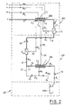
- the above-mentioned cooling is actuated first by a second cryogenic heat exchanger 350 (located in the second cryogenic section 300) and lastly by a third Joule-Thompson valve 30 (see figure 2 ).
- the second cryogenic exchanger 350 involves two circuits F 1 ,F 2 , being a fifth and sixth circuit, with the fifth circuit F 1 , crossed by the fifth flow ⁇ 5 .
- the second circuit F 2 is crossed by a seventh flow ⁇ 7 which is the sum of the sixth flow ⁇ 6 and a flow of methane vapours ⁇ VM of which more in the following.
- the flow ⁇ 6 is destined, in the exchanger 350, to provide the frigories for cooling the fifth flow ⁇ 5 ; for this purpose (see figure 2 ) a fourth Joule-Thompson valve 50 is included in the pipeline 23, which cools the sixth flow ⁇ 6 .
- the flow ⁇ 7 enters the relative circuit F 2 at about -142°C, crosses it and heats up; it follows that the steam ⁇ VM threshold passes to the gaseous phase of the methane.
- the seventh flow ⁇ 7 is directed, by means of a pipeline 24, into the fourth circuit C 4 of the first cryogenic exchanger 250 where it renders further frigories; at the outlet of the fourth circuit C 4 , the flow ⁇ 7 is sent to one of the inlets of the third compression stage C to constitute a recycling flow.
- the fifth flow ⁇ 5 at the outlet of the second cryogenic exchanger 350 has a temperature and pressure that are respectively about -138°C and 15 bar.
- the third Joule-Thompson valve 30 causes a further lowering of the temperature (up to - 156°C) and the pressure (about 1.8 bar) which causes liquefaction of the methane; flow ⁇ L .
- the flow of liquid methane ⁇ L is conveyed into the storage station 400, precisely into a cryogenic tank 450 ( figure 2 ).
- the methane vapours, flow ⁇ VM which are generated by the methane contained in the tank, are conveyed by means of a pipeline 34 into the sixth circuit F 2 of the second cryogenic exchanger 350 to constitute the seventh flow ⁇ 7 which has already been mentioned in the foregoing.
- the first flow ⁇ 1 is about 39% of ⁇ ; obviously the recycling flow ⁇ 2 (the one sent to one of the inlets of the first stage A of the compressor 5) is 61 % of ⁇ .
- the third flow ⁇ 3 is about 29.5% of the main flow ⁇ , while the recycling flow ⁇ 4 (sent to one of the inlets of the second compression stage B) is 9.5% thereof.
- the flow ⁇ L of methane liquid is about 25.8% of the main flow, while the recycling flow ⁇ 7 (sent to one of the inlets of the third compression stage C) is about 3.7% thereof.
- a flow of methane is collected from the supply network 1 thereof that is such as to reintegrate the liquefied methane and so as to enable supply to the gas motor 10.
- the motor 10-compressor 5 group supplies the methane with the power required for circulating in the plant with the aim of cooling and liquefying an amount thereof.
- the lowering of the methane to cryogenic levels is entrusted to the main flow ⁇ , first flow ⁇ 1 and fifth flow ⁇ 5 which are cooled following the crossing of the corresponding first 10, second 20 and third 30 Joule-Thompson valve.
- the main flow ⁇ is also cooled by the first cryogenic exchanger 250 due to the frigories yielded thereto, more precisely the first circuit C 1 , from flows ⁇ 2 , ⁇ 4 , ⁇ 7 passing in circuits C 2 ,C 3 ,C 4 of the heat exchanger 250.
- the fifth flow ⁇ 5 is cooled, upstream of the third Joule-Thompson valve, by the second cryogenic exchanger 250; the cooling is made possible by the accentuated cooling of the sixth flow ⁇ 6 by means of the fourth Joule-Thompson valve 50.
- the plant of the invention comprises the above-mentioned power section 100, the first and second cryogenic section 300, 400 and lastly the storage section 400.
- the power section comprises the gas motor 10 supplied by the low-pressure methane gas network 1 and the comburent part ⁇ S separated from the filter 2 by the purified methane.
- the first cryogenic section 200 is supplied by the power section 100 via the main flow and, in turn, supplies the main flow via the recycling flows ⁇ 2 , ⁇ 4 , ⁇ 7 .
- the second cryogenic section 300 is supplied by the first cryogenic section via the main flow ⁇ 1 and, in turn, supplies the main flow via the recycling flows ⁇ 4 , ⁇ 7 .
- the storage section is supplied by the liquid flow ⁇ L coming from the second section 300, and in turn the second section 300 is supplied by the methane vapour flow ⁇ VM .
- the plant of the invention only uses the methane gas flow ⁇ N collected from the supply network 1.
- the motor 10, of the gas motor type, which provides the power to the plate is supplied by an amount of flow ⁇ F collected by the network that is mixed with the comburent substances ⁇ S separated by the methane gas by means of the filter 2.
- the above-described and illustrated plant is advantageously provided for obtaining medium liquefied methane gas flows, for example comprised between 5 and 20 tonnes of methane per day.
Landscapes
- Engineering & Computer Science (AREA)
- Physics & Mathematics (AREA)
- Mechanical Engineering (AREA)
- Thermal Sciences (AREA)
- General Engineering & Computer Science (AREA)
- Chemical & Material Sciences (AREA)
- Chemical Kinetics & Catalysis (AREA)
- General Chemical & Material Sciences (AREA)
- Oil, Petroleum & Natural Gas (AREA)
- Combustion & Propulsion (AREA)
- Separation By Low-Temperature Treatments (AREA)
Applications Claiming Priority (1)
| Application Number | Priority Date | Filing Date | Title |
|---|---|---|---|
| ITBO20150008 | 2015-01-14 |
Publications (2)
| Publication Number | Publication Date |
|---|---|
| EP3045849A2 true EP3045849A2 (de) | 2016-07-20 |
| EP3045849A3 EP3045849A3 (de) | 2016-07-27 |
Family
ID=52597051
Family Applications (1)
| Application Number | Title | Priority Date | Filing Date |
|---|---|---|---|
| EP16151024.3A Withdrawn EP3045849A3 (de) | 2015-01-14 | 2016-01-13 | Anlage zur verflüssigung von methangas |
Country Status (1)
| Country | Link |
|---|---|
| EP (1) | EP3045849A3 (de) |
Cited By (2)
| Publication number | Priority date | Publication date | Assignee | Title |
|---|---|---|---|---|
| WO2018141950A1 (fr) * | 2017-02-03 | 2018-08-09 | Engie | Installation de production de bio-méthane et procédé de pilotage d'une telle installation |
| IT201700031616A1 (it) * | 2017-03-22 | 2018-09-22 | S Tra Te G I E Srl | Impianto di liquefazione del metano con relativo sistema di controllo di processo |
Family Cites Families (3)
| Publication number | Priority date | Publication date | Assignee | Title |
|---|---|---|---|---|
| GB1054489A (de) * | 1964-07-15 | |||
| US6564578B1 (en) * | 2002-01-18 | 2003-05-20 | Bp Corporation North America Inc. | Self-refrigerated LNG process |
| WO2009057179A2 (en) * | 2007-10-30 | 2009-05-07 | G.P.T. S.R.L. | Small-scale plant for production of liquified natural gas |
-
2016
- 2016-01-13 EP EP16151024.3A patent/EP3045849A3/de not_active Withdrawn
Non-Patent Citations (1)
| Title |
|---|
| None |
Cited By (4)
| Publication number | Priority date | Publication date | Assignee | Title |
|---|---|---|---|---|
| WO2018141950A1 (fr) * | 2017-02-03 | 2018-08-09 | Engie | Installation de production de bio-méthane et procédé de pilotage d'une telle installation |
| FR3062657A1 (fr) * | 2017-02-03 | 2018-08-10 | Engie | Installation de production de bio-methane et procede de pilotage d'une telle installation |
| IT201700031616A1 (it) * | 2017-03-22 | 2018-09-22 | S Tra Te G I E Srl | Impianto di liquefazione del metano con relativo sistema di controllo di processo |
| WO2018173082A1 (en) * | 2017-03-22 | 2018-09-27 | S.Tra.Te.G.I.E. S.R.L. | Plant for the liquefation of methane with relative process control system |
Also Published As
| Publication number | Publication date |
|---|---|
| EP3045849A3 (de) | 2016-07-27 |
Similar Documents
| Publication | Publication Date | Title |
|---|---|---|
| AU2016292348B9 (en) | Increasing efficiency in an LNG production system by pre-cooling a natural gas feed stream | |
| CA2775449C (en) | Methods of natural gas liquefaction and natural gas liquefaction plants utilizing multiple and varying gas streams | |
| US9528758B2 (en) | Method and system for regulation of cooling capacity of a cooling system based on a gas expansion process | |
| US20140083132A1 (en) | Process for liquefaction of natural gas | |
| CN105102913B (zh) | 天然气液化方法和装置 | |
| US10254041B2 (en) | System and method for processing a hydrocarbon-comprising fluid | |
| US7225636B2 (en) | Apparatus and methods for processing hydrocarbons to produce liquified natural gas | |
| US20240093936A1 (en) | Refrigerant supply to a cooling facility | |
| RU2016101068A (ru) | Единый каскадный процесс испарения и извлечения остатка сжиженного природного газа в применении, связанном с плавучими резервуарами | |
| US10281203B2 (en) | Method for liquefaction of industrial gas by integration of methanol plant and air separation unit | |
| US10788259B1 (en) | Modular, mobile and scalable LNG plant | |
| CN104136870A (zh) | 用于使富co2气体液化的方法和设备 | |
| EP3045849A2 (de) | Anlage zur verflüssigung von methangas | |
| AU2015388393B2 (en) | Natural gas production system and method | |
| US11097220B2 (en) | Method of preparing natural gas to produce liquid natural gas (LNG) | |
| EP2796819B1 (de) | Verfahren und Vorrichtung zur Verflüssigung von Erdgas | |
| CN220472018U (zh) | 高压天然气两级膨胀液化装置 | |
| CN108474613B (zh) | 用于液化天然气和氮气的方法 | |
| US20190310014A1 (en) | Device and method for liquefying a natural gas and ship comprising such a device | |
| TW201920891A (zh) | 天然氣的製造裝置以及天然氣的製造方法 | |
| KR20230034899A (ko) | 천연 가스의 액화를 위한 통합 질소 제거 | |
| CN104412055A (zh) | 控制温度以液化气体的方法及使用该方法的制备设备 | |
| EP1941218A1 (de) | Vorrichtung und verfahren zur verarbeitung von kohlenwasserstoffen zur erzeugung von verflüssigtem erdgas | |
| CN110230916A (zh) | 一种用于深冷空分联产lng的装置 |
Legal Events
| Date | Code | Title | Description |
|---|---|---|---|
| PUAI | Public reference made under article 153(3) epc to a published international application that has entered the european phase |
Free format text: ORIGINAL CODE: 0009012 |
|
| PUAL | Search report despatched |
Free format text: ORIGINAL CODE: 0009013 |
|
| AK | Designated contracting states |
Kind code of ref document: A2 Designated state(s): AL AT BE BG CH CY CZ DE DK EE ES FI FR GB GR HR HU IE IS IT LI LT LU LV MC MK MT NL NO PL PT RO RS SE SI SK SM TR |
|
| AX | Request for extension of the european patent |
Extension state: BA ME |
|
| AK | Designated contracting states |
Kind code of ref document: A3 Designated state(s): AL AT BE BG CH CY CZ DE DK EE ES FI FR GB GR HR HU IE IS IT LI LT LU LV MC MK MT NL NO PL PT RO RS SE SI SK SM TR |
|
| AX | Request for extension of the european patent |
Extension state: BA ME |
|
| RIC1 | Information provided on ipc code assigned before grant |
Ipc: F25J 1/00 20060101AFI20160621BHEP Ipc: F25J 1/02 20060101ALI20160621BHEP |
|
| 17P | Request for examination filed |
Effective date: 20170125 |
|
| RBV | Designated contracting states (corrected) |
Designated state(s): AL AT BE BG CH CY CZ DE DK EE ES FI FR GB GR HR HU IE IS IT LI LT LU LV MC MK MT NL NO PL PT RO RS SE SI SK SM TR |
|
| 17Q | First examination report despatched |
Effective date: 20171205 |
|
| STAA | Information on the status of an ep patent application or granted ep patent |
Free format text: STATUS: THE APPLICATION IS DEEMED TO BE WITHDRAWN |
|
| 18D | Application deemed to be withdrawn |
Effective date: 20180616 |