EP3045840B1 - Air conditioner - Google Patents
Air conditioner Download PDFInfo
- Publication number
- EP3045840B1 EP3045840B1 EP14847465.3A EP14847465A EP3045840B1 EP 3045840 B1 EP3045840 B1 EP 3045840B1 EP 14847465 A EP14847465 A EP 14847465A EP 3045840 B1 EP3045840 B1 EP 3045840B1
- Authority
- EP
- European Patent Office
- Prior art keywords
- refrigerant
- refrigerant tube
- air conditioner
- valve
- indoor
- Prior art date
- Legal status (The legal status is an assumption and is not a legal conclusion. Google has not performed a legal analysis and makes no representation as to the accuracy of the status listed.)
- Active
Links
Images



Classifications
-
- F—MECHANICAL ENGINEERING; LIGHTING; HEATING; WEAPONS; BLASTING
- F25—REFRIGERATION OR COOLING; COMBINED HEATING AND REFRIGERATION SYSTEMS; HEAT PUMP SYSTEMS; MANUFACTURE OR STORAGE OF ICE; LIQUEFACTION SOLIDIFICATION OF GASES
- F25B—REFRIGERATION MACHINES, PLANTS OR SYSTEMS; COMBINED HEATING AND REFRIGERATION SYSTEMS; HEAT PUMP SYSTEMS
- F25B30/00—Heat pumps
- F25B30/02—Heat pumps of the compression type
-
- F—MECHANICAL ENGINEERING; LIGHTING; HEATING; WEAPONS; BLASTING
- F24—HEATING; RANGES; VENTILATING
- F24F—AIR-CONDITIONING; AIR-HUMIDIFICATION; VENTILATION; USE OF AIR CURRENTS FOR SCREENING
- F24F1/00—Room units for air-conditioning, e.g. separate or self-contained units or units receiving primary air from a central station
- F24F1/06—Separate outdoor units, e.g. outdoor unit to be linked to a separate room comprising a compressor and a heat exchanger
- F24F1/26—Refrigerant piping
- F24F1/32—Refrigerant piping for connecting the separate outdoor units to indoor units
-
- F—MECHANICAL ENGINEERING; LIGHTING; HEATING; WEAPONS; BLASTING
- F25—REFRIGERATION OR COOLING; COMBINED HEATING AND REFRIGERATION SYSTEMS; HEAT PUMP SYSTEMS; MANUFACTURE OR STORAGE OF ICE; LIQUEFACTION SOLIDIFICATION OF GASES
- F25B—REFRIGERATION MACHINES, PLANTS OR SYSTEMS; COMBINED HEATING AND REFRIGERATION SYSTEMS; HEAT PUMP SYSTEMS
- F25B13/00—Compression machines, plants or systems, with reversible cycle
-
- F—MECHANICAL ENGINEERING; LIGHTING; HEATING; WEAPONS; BLASTING
- F25—REFRIGERATION OR COOLING; COMBINED HEATING AND REFRIGERATION SYSTEMS; HEAT PUMP SYSTEMS; MANUFACTURE OR STORAGE OF ICE; LIQUEFACTION SOLIDIFICATION OF GASES
- F25B—REFRIGERATION MACHINES, PLANTS OR SYSTEMS; COMBINED HEATING AND REFRIGERATION SYSTEMS; HEAT PUMP SYSTEMS
- F25B41/00—Fluid-circulation arrangements
- F25B41/20—Disposition of valves, e.g. of on-off valves or flow control valves
-
- F—MECHANICAL ENGINEERING; LIGHTING; HEATING; WEAPONS; BLASTING
- F25—REFRIGERATION OR COOLING; COMBINED HEATING AND REFRIGERATION SYSTEMS; HEAT PUMP SYSTEMS; MANUFACTURE OR STORAGE OF ICE; LIQUEFACTION SOLIDIFICATION OF GASES
- F25B—REFRIGERATION MACHINES, PLANTS OR SYSTEMS; COMBINED HEATING AND REFRIGERATION SYSTEMS; HEAT PUMP SYSTEMS
- F25B49/00—Arrangement or mounting of control or safety devices
- F25B49/02—Arrangement or mounting of control or safety devices for compression type machines, plants or systems
-
- F—MECHANICAL ENGINEERING; LIGHTING; HEATING; WEAPONS; BLASTING
- F25—REFRIGERATION OR COOLING; COMBINED HEATING AND REFRIGERATION SYSTEMS; HEAT PUMP SYSTEMS; MANUFACTURE OR STORAGE OF ICE; LIQUEFACTION SOLIDIFICATION OF GASES
- F25B—REFRIGERATION MACHINES, PLANTS OR SYSTEMS; COMBINED HEATING AND REFRIGERATION SYSTEMS; HEAT PUMP SYSTEMS
- F25B2313/00—Compression machines, plants or systems with reversible cycle not otherwise provided for
- F25B2313/023—Compression machines, plants or systems with reversible cycle not otherwise provided for using multiple indoor units
- F25B2313/0231—Compression machines, plants or systems with reversible cycle not otherwise provided for using multiple indoor units with simultaneous cooling and heating
-
- F—MECHANICAL ENGINEERING; LIGHTING; HEATING; WEAPONS; BLASTING
- F25—REFRIGERATION OR COOLING; COMBINED HEATING AND REFRIGERATION SYSTEMS; HEAT PUMP SYSTEMS; MANUFACTURE OR STORAGE OF ICE; LIQUEFACTION SOLIDIFICATION OF GASES
- F25B—REFRIGERATION MACHINES, PLANTS OR SYSTEMS; COMBINED HEATING AND REFRIGERATION SYSTEMS; HEAT PUMP SYSTEMS
- F25B2313/00—Compression machines, plants or systems with reversible cycle not otherwise provided for
- F25B2313/025—Compression machines, plants or systems with reversible cycle not otherwise provided for using multiple outdoor units
- F25B2313/0252—Compression machines, plants or systems with reversible cycle not otherwise provided for using multiple outdoor units with bypasses
-
- F—MECHANICAL ENGINEERING; LIGHTING; HEATING; WEAPONS; BLASTING
- F25—REFRIGERATION OR COOLING; COMBINED HEATING AND REFRIGERATION SYSTEMS; HEAT PUMP SYSTEMS; MANUFACTURE OR STORAGE OF ICE; LIQUEFACTION SOLIDIFICATION OF GASES
- F25B—REFRIGERATION MACHINES, PLANTS OR SYSTEMS; COMBINED HEATING AND REFRIGERATION SYSTEMS; HEAT PUMP SYSTEMS
- F25B2313/00—Compression machines, plants or systems with reversible cycle not otherwise provided for
- F25B2313/027—Compression machines, plants or systems with reversible cycle not otherwise provided for characterised by the reversing means
- F25B2313/02741—Compression machines, plants or systems with reversible cycle not otherwise provided for characterised by the reversing means using one four-way valve
-
- F—MECHANICAL ENGINEERING; LIGHTING; HEATING; WEAPONS; BLASTING
- F25—REFRIGERATION OR COOLING; COMBINED HEATING AND REFRIGERATION SYSTEMS; HEAT PUMP SYSTEMS; MANUFACTURE OR STORAGE OF ICE; LIQUEFACTION SOLIDIFICATION OF GASES
- F25B—REFRIGERATION MACHINES, PLANTS OR SYSTEMS; COMBINED HEATING AND REFRIGERATION SYSTEMS; HEAT PUMP SYSTEMS
- F25B2400/00—Component parts or details not otherwise provided for in this subclass
- F25B2400/06—Several compression cycles arranged in parallel
-
- F—MECHANICAL ENGINEERING; LIGHTING; HEATING; WEAPONS; BLASTING
- F25—REFRIGERATION OR COOLING; COMBINED HEATING AND REFRIGERATION SYSTEMS; HEAT PUMP SYSTEMS; MANUFACTURE OR STORAGE OF ICE; LIQUEFACTION SOLIDIFICATION OF GASES
- F25B—REFRIGERATION MACHINES, PLANTS OR SYSTEMS; COMBINED HEATING AND REFRIGERATION SYSTEMS; HEAT PUMP SYSTEMS
- F25B2400/00—Component parts or details not otherwise provided for in this subclass
- F25B2400/07—Details of compressors or related parts
- F25B2400/075—Details of compressors or related parts with parallel compressors
-
- F—MECHANICAL ENGINEERING; LIGHTING; HEATING; WEAPONS; BLASTING
- F25—REFRIGERATION OR COOLING; COMBINED HEATING AND REFRIGERATION SYSTEMS; HEAT PUMP SYSTEMS; MANUFACTURE OR STORAGE OF ICE; LIQUEFACTION SOLIDIFICATION OF GASES
- F25B—REFRIGERATION MACHINES, PLANTS OR SYSTEMS; COMBINED HEATING AND REFRIGERATION SYSTEMS; HEAT PUMP SYSTEMS
- F25B2400/00—Component parts or details not otherwise provided for in this subclass
- F25B2400/13—Economisers
-
- F—MECHANICAL ENGINEERING; LIGHTING; HEATING; WEAPONS; BLASTING
- F25—REFRIGERATION OR COOLING; COMBINED HEATING AND REFRIGERATION SYSTEMS; HEAT PUMP SYSTEMS; MANUFACTURE OR STORAGE OF ICE; LIQUEFACTION SOLIDIFICATION OF GASES
- F25B—REFRIGERATION MACHINES, PLANTS OR SYSTEMS; COMBINED HEATING AND REFRIGERATION SYSTEMS; HEAT PUMP SYSTEMS
- F25B2600/00—Control issues
- F25B2600/25—Control of valves
- F25B2600/2501—Bypass valves
Definitions
- the present invention relates to an air conditioner, and more particularly, an air conditioner capable of being applied to various types.
- the present invention relates to an air conditioner having a plurality of indoor units are provided such that the air conditioner is capable of converting a simultaneous operation of cooling and heating or a switching operation of cooling and heating upon a user's request.
- Conventional simultaneous cooling and heating type air conditioners include a compressor, an outdoor heat exchanger, a four-way valve, one outdoor unit with an expansion valve, indoor units, a distributor including opening and closing valves, and a high pressure gas pipe, a low pressure gas pipe and a high pressure liquid line which are provided between the outdoor unit and indoor units.
- Such simultaneous cooling and heating type air conditioners perform, by selectively opening and closing the opening and closing valves of the distributor, an all indoor units heating operation in which all of the indoor unit heats, an all indoor units cooling operation in which all of the indoor units cool, a heating-oriented operation in which a few indoor units perform a cooling operation and the rest of the indoor units perform a heating operation, and a cooling-oriented operation in which a few indoor units heat and the rest of the indoor units cool.
- cooling and heating switching type air conditioners include a compressor, an outdoor heat exchanger, a four-way valve, one outdoor unit with an expansion valve, indoor units, and a gas pipe and a liquid line provided between the outdoor unit and the indoor units.
- Such cooling and heating switching type air conditioners perform, by switching the flow of a refrigerant with the four-way valve, an all indoor units heating operation in which all of the indoor units heat, an all indoor units cooling operation in which all of the indoor units cool.
- US2013/0019613A1 and EP1645810A2 relate to multi-type air conditioners.
- the outdoor unit of a simultaneous cooling and heating type air conditioner and the outdoor unit of a cooling and heating switching type air conditioner are not compatible with each other due to different internal configurations, there is a problem in that, when a type is changed between the simultaneous cooling and heating type air conditioner and the cooling and heating switching type air conditioner, the outdoor unit also needs to be changed.
- An air conditioner in accordance with the present invention is defined by claim 1. It includes: an outdoor unit having an outdoor heat exchanger and a compressor installed therein; a plurality of indoor units which are connected to the outdoor unit and include an indoor heat exchanger installed therein; a four-way valve provided on the discharge part side of the compressor; a refrigerant tube having first to third refrigerant tubes and configured to connect the four-way valve and the indoor heat exchanger, in which the first refrigerant tube is branched between the four-way valve and the outdoor heat exchanger such that some of a refrigerant discharged from the compressor is fed into the indoor heat exchanger while bypassing the outdoor heat exchanger, the second refrigerant tube is connected to the four-way valve to feed all of a refrigerant discharged from the compressor into the indoor heat exchanger, and the third refrigerant tube is connected to the second refrigerant tube in parallel; and a heat pump valve provided at the third refrigerant tube to selectively close the third refrigerant tube.
- the opening and closing of the heat pump valve may be controlled in accordance with operation methods of the plurality of indoor units.
- the air conditioner may further include a distributor disposed between the outdoor unit and the plurality of indoor units to distribute a refrigerant such that each of the plurality of indoor units perform a cooling or heating operation at the same time.
- the heat pump valve may be closed when the air conditioner is operating.
- the outdoor unit and the plurality of indoor units may be directly connected such that all of the plurality of indoor units to perform a cooling or heating operation at the same time.
- the heat pump valve may be open when the air conditioner is operating.
- the refrigerant discharged from the compressor may alternatively flow into any one of the first refrigerant tube and the second refrigerant tube when the heat pump valve is closed.
- the refrigerant discharged from the compressor or passed through the indoor heat exchanger may flow into at least any one of the second refrigerant tube and the third refrigerant tube when the heat pump valve is open.
- the air conditioner may further include a gas pipe through which the refrigerant flows between the outdoor unit and the plurality of indoor units.
- Each of the first refrigerant tube, the second refrigerant tube, and the third refrigerant tube may have one end communicating with the gas pipe.
- the gas pipe may include a high pressure gas pipe through which a high pressure refrigerant flows and a low pressure gas pipe through which a low pressure refrigerant flows.
- the first refrigerant tube, the second refrigerant tube, and the third refrigerant tube may communicate with the high pressure gas pipe.
- the first refrigerant tube may include a check valve for preventing backflow and an opening and closing valve which closes the first refrigerant tube.
- the opening and closing valve may be closed to allow the plurality of indoor units to perform all cooling or all heating, and the heat pump valve may be open to allow bidirectional refrigerant movement in the third refrigerant tube.
- the four-way valve may include a first port connected to a discharge part of the compressor, a second port which communicates with the first refrigerant tube and the outdoor heat exchanger, and a third port which communicates with the second refrigerant tube and the third refrigerant tube.
- the second refrigerant tube may include a check valve for preventing backflow.
- the heat pump valve may be a manual opening and closing valve, a solenoid valve or an electronic expansion valve.
- the outdoor unit of an air conditioner in accordance with the spirit of the present invention having a plurality of indoor units includes a compressor for compressing refrigerant; an outdoor heat exchanger for heat-exchanging with refrigerant; a four-way valve provided on the discharge part side of the compressor; a high pressure gas pipe which guides a refrigerant between the indoor unit and the pipe and through which a high pressure gas is guided, a low pressure gas pipe through which a low pressure gas is guided, and a liquid line which guides a liquid refrigerant; a high pressure gas service valve and a low pressure gas service valve respectively provided in the outdoor unit to open and close the high pressure gas pipe and the low pressure gas pipe; and a refrigerant tube provided between the high pressure gas service valve and the four-way valve, including a simultaneous type refrigerant tube for guiding a refrigerant discharged from the compressor to the high pressure gas pipe in one direction through the four-way valve and a switching type refrigerant tube provided for allowing a refrigerant to move bi
- the outdoor unit may further include a heat pump valve provided at the switching type refrigerant tube and capable of opening and closing the switching type refrigerant tube.
- the simultaneous type refrigerant tube and the switching type refrigerant tube may be connected in parallel between the four-way valve and the high pressure gas pipe.
- the opening and closing of the heat pump valve and opening and closing of the low pressure gas service valve may be conversely performed.
- the heat pump valve may be closed.
- the heat pump valve may be open and the low pressure service valve may be closed.
- An air conditioner of the present invention includes one outdoor unit 1 and is capable of being applied to both a simultaneous cooling and heating type air conditioner and a cooling and heating switching type air conditioner, thereby flexibly responding to the purpose of use.
- an all indoor units cooling operation indicates that all of a plurality of indoor units 100a, 100b, 100c, and 100d (hereinafter, all of the plurality of indoor units are identified by reference numeral 100) perform a cooling operation while an all indoor units heating operation indicates that all of the plurality of indoor units 100 perform a heating operation.
- a cooling-oriented operation indicates that some of the plurality of indoor units 100 perform a cooling operation while the others perform a heating operation, a total cooling load of the indoor unit 100 is greater than a total heating load, and a four-way valve of an outdoor unit is in a cooling state.
- a heating-oriented operation indicates that some of the plurality of indoor units 100 perform a cooling operation while the others perform a heating operation, a total heating load of the indoor unit 100 is greater than a total cooling load, and a four-way valve of the outdoor unit is in a heating mode.
- a simultaneous cooling and heating type air conditioner is an air conditioner provided for not only performing a cooling-oriented operation and a heating-oriented operation but also performing an all indoor units cooling operation and an all indoor units heating operation.
- a cooling and heating switching type air conditioner is capable of performing an all indoor units cooling operation and an all indoor units heating operation.
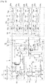
- FIG. 1 illustrates a piping diagram of an air conditioner according to an exemplary embodiment of the present invention.
- an air conditioner according to the present invention includes a plurality of indoor units 100 and at least one outdoor unit 1.
- a distributor 120 connecting to the plurality of indoor units 100 and at least one outdoor unit 1 may be further included.
- the plurality of indoor units 100 respectively include indoor heat exchangers 102a, 102b, 102c, and 102d which cool and heat indoor air while a refrigerant and the indoor air are heat-exchanging, and indoor expansion devices 104a, 104b, 104c, and 104d for expanding the refrigerant flowing toward the indoor heat exchangers 102a, 102b, 102c, and 102d.
- the indoor expansion devices 104a, 104b, 104c, and 104d may be an electronic expansion valve (EEV) capable of controlling the flow of the refrigerant.
- the electronic expansion valve may control flow of refrigerant by adjusting opening degree.
- Each of the indoor heat exchangers 102a, 102b, 102c, and 102d of the plurality of indoor units 100 is connected by indoor unit tubes 106a, 106b, 106c, and 106d in a relation with the distributor 120, and each of the indoor expansion devices 104a, 104b, 104c, and 104d thereof is connected by indoor liquid lines 108a, 108b, 108c, and 108d in a relation with the distributor 120.
- the at least one outdoor unit 1 includes a compression part 10, an outdoor heat exchanger 20, an outdoor expansion device 50, and a four-way valve 30.
- a compression part 10 an outdoor heat exchanger 20, an outdoor expansion device 50, and a four-way valve 30.
- an example having one outdoor unit 1 will be described.
- the compression part 10 includes one or more compressors 12 for compressing the refrigerant.
- the compression part 10 is described to include a plurality of compressors 12.
- the plurality of compressors 12 may be disposed in parallel. Discharge flow paths of the plurality of compressors 12 are connected to the four-way valve 30, and an accumulator 70 is installed on an inflow path.
- the accumulator 70 connected to the plurality of compressors 12 accumulates a liquid refrigerant and allows a gaseous refrigerant to be sucked into the plurality of compressors 12.
- a compressor inflow tube 14 for connecting the plurality of compressors 12 and the accumulator 70 is provided therebetween, and an accumulator inflow tube 72 for connecting the accumulator 70 and the four-way valve 30 is provided therebetween.
- oil separators 16 for separating the refrigerant and oil
- check valves 17 for preventing the backflow of a refrigerant
- the four-way valve 30 are installed.
- an oil recovery path 18 is connected for recovering the oil separated from the refrigerant in the oil separator 16 in the compressor inflow tube 14.
- the refrigerant is guided through a gas pipe 60 and a liquid line 66 between the outdoor unit 1 and the distributor 120.
- the gas pipe 60 includes a high pressure gas pipe 62 in which high pressure gas is guided and a low pressure gas pipe 64 in which low pressure gas is guided.
- a liquid refrigerant flows in the liquid line 66.
- a high pressure gas service valve 63 and a low pressure gas service valve 65 are respectively provided for adjusting the opening degree or opening and closing the high pressure gas pipe 62 and the low pressure gas pipe 64
- a liquid line service valve 67 is provided for adjusting the opening degree or opening and closing the liquid line 66.
- An outdoor heat exchanger 20 functions as a condenser during the all indoor units cooling operation or a cooling-oriented operation, and functions as an evaporator during an all indoor units heating operation or a heating-oriented operation.
- the refrigerant inside the outdoor heat exchanger 20 is capable of heat-exchanging with outdoor air as a circulating fluid.
- the outdoor expansion device 50 does not expand a refrigerant when the refrigerant passed through the outdoor heat exchanger 20 is passing, but expands a refrigerant when the refrigerant not passed through the outdoor heat exchanger 20 is passing.
- the outdoor expansion device 50 may be disposed between the outdoor heat exchanger 20 and the distributor 120, and may include an outdoor expansion valve 54 and an outdoor check valve 52.
- an outdoor check valve 52 for preventing backflow may be provided at a refrigerant flow path for a refrigerant flowing from the outdoor heat exchanger 20 to the distributor 120
- an outdoor check valve 52 for preventing backflow and the outdoor expansion valve 54 may be provided at a refrigerant flow path for a refrigerant flowing from the distributor 120 to the outdoor heat exchanger 20.
- the first outdoor check valve 52a may be disposed in parallel with the second outdoor check valve 52b and the outdoor expansion valve 54.
- the outdoor expansion valve 54 may be, for example, an electronic expansion valve (EEV).
- the four-way valve 30 is provided on the discharge part side of the compressor 12.
- the four-way valve 30 allows the refrigerant compressed in the plurality of compressors 12 to flow into the outdoor heat exchanger 20 when an all indoor units cooling operation or a cooling-oriented operation is performed, and allows the refrigerant passed through the outdoor heat exchanger 20 to flow toward the compressors 12 when an all indoor units heating operation or a heating-oriented operation is performed.
- a first port 30a is connected on the discharge side of the compressors 12 through an oil separator 16, and a second port 30b communicates with the high pressure gas pipe 62 through a first refrigerant tube 41, and, at the same time, is connected to the liquid line 66 through the outdoor heat exchanger 20 and the outdoor expansion device 50.
- a third port 30c communicates with the high pressure gas pipe 62 through a second refrigerant tube 42 and a third refrigerant tube 43, and a fourth port 30d is connected to the accumulator 70.
- a refrigerant tube 40 communicating with the four-way valve 30 may include the first refrigerant tube 41, the second refrigerant tube 42, and the third refrigerant tube 43.
- the first refrigerant tube 41 is branched between the second port 30b and the outdoor heat exchanger 20 and is connected to the high pressure gas pipe 62.
- the first refrigerant tube 41 may be provided to be branched between the four-way valve 30 and the indoor heat exchangers 102a, 102b, 102c, and 102d such that some of the refrigerant discharged from the compressor 12 bypasses the outdoor heat exchanger 20 and is fed into the indoor heat exchangers 102a, 102b, 102c, and 102d.
- the rest of the refrigerant except some of the refrigerant fed to the first refrigerant tube 41 flow into the outdoor heat exchanger 20.
- the first refrigerant tube 41 may include an opening and closing valve 41b for opening and closing the first refrigerant tube 41 and a check valve 41a for preventing the backflow of a refrigerant from the high pressure gas pipe 62.
- a quantity of a refrigerant flowing into the high pressure gas pipe 62 through the first refrigerant tube 41 and a quantity of the refrigerant flowing into the outdoor heat exchanger 20 may be adjusted.
- the second refrigerant tube 42 is connected to the third port 30c and communicates with the high pressure gas pipe 62.
- one end is connected to a connecting part 41c of the high pressure gas pipe 62 and the first refrigerant tube 41, and the other end is connected to the third port 30c.
- the second refrigerant tube 42 is controlled such that all of the refrigerants discharged from the compressors 12 pass through the high pressure gas pipe 62.
- a refrigerant separately flows into the first refrigerant tube 41 and outdoor heat exchanger 20, or all of the refrigerants are capable of flowing through the second refrigerant tube 42.
- the second refrigerant tube 42 may include a check valve 42b which prevents backflow from the high pressure gas pipe 62 side.
- the third refrigerant tube 43 is provided to be branched from the second refrigerant tube 42.
- the third refrigerant tube 43 may be disposed to be connected to the second refrigerant tube 42 in parallel.
- one end and the other end thereof communicate with the second refrigerant tube 42, and a heat pump valve 44 may be provided to be connected to the check valve 42a of the second refrigerant tube 42 in parallel.
- the heat pump valve 44 is provided so as to be capable of opening and closing the third refrigerant tube 43.
- the opening and closing of the heat pump valve 44 is differently controlled depending on the operation methods of the plurality of indoor units 100. As described hereafter, when applied to a simultaneous cooling and heating type air conditioner, the heat pump valve 44 is closed, and when applied to a cooling and heating switching type air conditioner, the heat pump valve 44 is open.
- the heat pump valve 44 may be composed of a manual opening, a closing valve, a solenoid valve or an electronic expansion valve.
- the refrigerant discharged from the compressor 12 and flowed to the high pressure gas pipe 62 through the first refrigerant tube 41 or the second refrigerant tube 42 is delivered into the indoor unit 100 via the distributor 120, thereby, a configuration for guiding the refrigerant in the backflow direction is not needed.
- the third refrigerant tube 43 is not used in the simultaneous cooling and heating type air conditioner, it can be closed using the heat pump valve 44.
- the heat pump valve 44 by opening the heat pump valve 44, a refrigerant flowing bidirectionally depending on the cooling and heating operation may be guided.
- first refrigerant tube 41, the second refrigerant tube 42, and the third refrigerant tube 43 are provided to communicate with the high pressure gas pipe 62.
- first refrigerant tube 41 and the second refrigerant tube 42 are active when the outdoor unit 1 of the present invention is applied to the simultaneous cooling and heating type air conditioner
- the first refrigerant tube 41 and the second refrigerant tube 42 may be a simultaneous type refrigerant tube 40a.
- the third refrigerant tube 43 since the third refrigerant tube 43 is active when the outdoor unit 1 of the present invention is applied to the cooling and heating switching type air conditioner, the third refrigerant tube 43 may be a switching type refrigerant tube 40b.
- the simultaneous type refrigerant tube 40a and the switching type refrigerant tube 40b may be connected between the four-way valve 30 and the high pressure gas pipe 62 in parallel.
- the outdoor unit 1 may further include a receiver 82, a refrigerant cooler 84, an outdoor heat exchanger valve 86, and a supercooling device 88.
- the refrigerant cooler 84 circulates a refrigerant to dissipate the heat of an inverter controller and functions as a heat sink of the inverter controller.
- the outdoor heat exchanger valve 86 as a configuration for controlling a quantity of the refrigerant flowing into the outdoor heat exchanger 20, may be provided between the receiver 82 and the outdoor heat exchanger 20.
- the supercooling device 88 is capable of securing a degree of supercooling of the refrigerant fed into the indoor unit 100 when a cooling operation is performed, and may be provided between the outdoor heat exchanger 20 and the outdoor expansion device 50.
- a bypass channel 90 is connected between the high pressure gas pipe 62 and the low pressure gas pipe 64, and the bypass channel 90 has an opening and closing valve for controlling pressure 92.
- the opening and closing valve for controlling pressure 92 is open, some of the refrigerant flowing through the high pressure gas pipe 62 passes through the bypass channel 90 and is merged with the refrigerant flowing through the low pressure gas pipe 64, and thus the pressure in the low pressure gas pipe 64 increases.
- the distributor 120 is connected to the plurality of indoor units 100 and the outdoor unit 1 to control the flow of a refrigerant.
- the distributor 120 is connected to the indoor unit 100 through the indoor unit tubes 106a, 106b, 106c, and 106d and the indoor liquid lines 108a, 108b, 108c, and 108d, and is connected to the outdoor unit 1 through the high pressure gas pipe 62, the liquid line 66, and the low pressure gas pipe 64.
- the high pressure gas pipe 62, the low pressure gas pipe 64, and the liquid line 66 may be branched in the distributor 120, and the branched liquid lines 66 are respectively connected to the indoor expansion devices 104a, 104b, 104c, and 104d. Also, the high pressure gas pipe 62 and the low pressure gas pipe 64 are respectively connected to the heat exchangers 102a, 102b, 102c, and 102d of the indoor unit 100 through heating valves 122a, 122b, 122c, and 122d and cooling valves 124a, 124b, 124c, and 124d in the distributor 120.
- the outlet sides of the heating valves 122a, 122b, 122c, and 122d are joined to communicate with the high pressure gas pipe 62, the outlet sides thereof communicate with the respective indoor heat exchangers 102a, 102b, 102c, and 102d of the indoor unit 100.
- the inflow sides of the cooling valves 124a, 124b, 124c, and 124d communicate with the respective indoor heat exchangers 102a, 102b, 102c, and 102d of the indoor unit 100, the outlet sides thereof are joined and communicate with the low pressure gas pipe 64.
- the cooling valves 124a and 124b may be open and the heating valves 122a and 122b may be closed.
- the cooling valve 124c and 124d may be closed and the heating valves 122c and 122d may be open.
- the cooling valves 124a, 124b, 124c, and 124d and the heating valves 122a, 122b, 122c, and 122d may be an electronic expansion valve (EEV) capable of adjusting the opening degree linearly or by stages.
- EEV electronic expansion valve
- the heat pump valve 44 of the outdoor unit 1 is closed to flow a refrigerant into the first refrigerant tube 41 or the second refrigerant tube 42, and the low pressure gas service valve 65 of the outdoor unit 1 is open.
- the heat pump valve 44 is open and the low pressure gas service valve 65 is closed. That is, the opening and closing of the heat pump valve 44 and the low pressure gas service valve 65 are conversely performed.
- the outdoor unit 1 of the present invention applied to the simultaneous cooling and heating type air conditioner is provided such that the refrigerant discharged from the compressor 12 after closing the heat pump valve 44 alternatively flows into any one of the first refrigerant tube 41 or the second refrigerant tube 42.
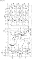
- FIG. 2 is a refrigerant flow diagram of an air conditioner according to an exemplary embodiment of the present invention.
- FIG. 2 is a refrigerant flow diagram showing a heating-oriented operation performed by a cooling and heating simultaneous type air conditioner.
- Thick arrows in the drawing indicate the flow of a high pressure refrigerant gas
- arrows with dotted lines indicate the flow of a low pressure refrigerant gas
- thin arrows indicate flow of a liquid refrigerant.
- the cooling valves 124c and 124d installed in the indoor units 100c and 100d are closed, and the heating valves 122c and 122d are open.
- the cooling valves 124a and 124b installed in the indoor units 100a and 100b are open, and the heating valves 122a and 122b are closed.
- a refrigerant compressed in the plurality of compressors 12 flows from the outdoor unit 1 to the distributor 120 via the second refrigerant tube 42 and the high pressure gas pipe 62, and then, is condensed in the indoor heat exchangers 102c and 102d of the indoor units 100c and 100d via the indoor unit tubes 106c and 106d.
- the condensed refrigerant passes the indoor expansion devices 104c and 104d without expansion and flows through the indoor liquid lines 108c and 108d in the indoor units 100c and 100d.
- the expanded refrigerant is evaporated in the indoor heat exchangers 102a and 102b of the indoor units 100a and 100b in the cooling operation, and then, passes through the low pressure gas pipe 64 via the indoor unit tubes 106a and 106b, and is sucked into the plurality of compressors 12.
- the rest of the refrigerant flowing in the indoor liquid lines 108c and 108d is fed into the outdoor expansion device 50 of the outdoor unit 1 through the liquid line 66 and expanded therein, then, is fed into the four-way valve 30 after being evaporated in the outdoor heat exchanger 20, and sucked into the plurality of compressors 12.
- FIG. 3 is a refrigerant flow diagram of an air conditioner according to an exemplary embodiment of the present invention.
- FIG. 3 is a refrigerant flow diagram showing a cooling-oriented operation performed by a simultaneous cooling and heating type air conditioner.
- the cooling valves 124c and 124d installed in the indoor units 100c and 100d are closed, and the heating valves 122c and 122d are open.
- the cooling valves 124a and 124b installed in the indoor unit 100a and 100b are open, and the heating valves 122a and 122b are closed.
- the four-way valve 30 connects the first port 30a and the second port 30b.
- a refrigerant compressed in the plurality of compressors 12 flows from the first port 30a to the second port 30b, some of the refrigerant flows into the high pressure gas pipe 62 through the first refrigerant tube 41, the rest of the refrigerant passes through the outdoor heat exchanger 20 and is fed into the indoor expansion devices 104a and 104b of the indoor units 100a and 100b in a cooling operation via the liquid line 66, and the refrigerant fed into the indoor expansion devices 104a and 104b is expanded in the indoor expansion devices 104a and 104b, and then, is evaporated in the indoor heat exchangers 102a and 102b.
- the evaporated refrigerant is then sent from the indoor units 100a and 100b in the cooling operation to the accumulator 70 through the indoor unit tubes 106a and 106b and the low pressure gas pipe 64, and then, compressed in the plurality of compressors 12.
- the refrigerant flowing into the high pressure gas pipe 62 through the first refrigerant tube 41 flows into the distributor 120 through the high pressure gas pipe 62, passes through the heating valves 122c and 122d, flows into the indoor heat exchangers 102c and 102d of the indoor units 100c and 100d in the heating operation, and condensed therein.
- the condensed refrigerant then passes through the indoor expansion devices 104c and 104d without expansion and is mixed with the refrigerant fed into the indoor expansion devices 104a and 104b of the indoor units 100a and 100b in the cooling operation through the liquid line 66.
- the refrigerant is fed to the indoor expansion devices 104a and 104b of the indoor units 100a and 100b in the cooling operation through the indoor liquid lines 108a and 108b of the indoor units 100a and 100b in the cooling operation or is fed to the outdoor unit side.
- the indoor heat exchangers 102a and 102b of the indoor units 100a and 100b in the cooling operation function as evaporators to cool an internal space
- the indoor heat exchangers 102c and 102d of the indoor units 100c and 100d in the heating operation function as condensers to heat the internal space.
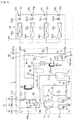
- FIG. 4 is a piping diagram of an air conditioner according to another exemplary embodiment of the present invention.
- FIGS. 4 , 5 , and 6 are drawings related to a cooling and heating switching type air conditioner.
- the cooling and heating switching type air conditioner includes the plurality of indoor units 100 as described above and at least one outdoor unit 1.
- the cooling and heating switching type air conditioner has a configuration in which the distributor 120 is omitted from the simultaneous cooling and heating type air conditioner, the descriptions related to the repetitive configurations are omitted.
- the indoor unit 100 and the outdoor unit 1 are directly connected through pipes.
- the outdoor unit 1 of the present invention applied to the cooling and heating switching type air conditioner is connected to the plurality of indoor units 100 by closing the low pressure gas pipe 64 and opening the heat pump valve 44.
- the high pressure gas pipe 62 serves as the refrigerant gas pipe 62a in the cooling and heating switching type air conditioner.
- Each of the indoor heat exchangers 102a, 102b, 102c, and 102d of the plurality of indoor units 100 is connected to the gas pipe 60 through the indoor unit tubes 106a, 106b, 106c, and 106d.
- Each of the indoor expansion devices 104a, 104b, 104c, and 104d is connected to the liquid line 66 through the indoor liquid lines 108a, 108b, 108c, and 108d.
- the outdoor expansion device 50 may be provided between the outdoor heat exchanger 20 and the indoor unit 100 and may include the outdoor expansion valve 54 and an outdoor check valve 52.
- an outdoor check valve 52 for preventing backflow may be provided at a refrigerant flow path for the refrigerant flowing from the outdoor heat exchanger 20 to the indoor unit 100
- an outdoor check valve 52 for preventing backflow and the outdoor expansion valve 54 may be provided at a refrigerant flow path for the refrigerant flowing from the indoor unit 100 to the outdoor heat exchanger 20.
- the first outdoor check valve 52a may be disposed in parallel with the second outdoor check valve 52b and the outdoor expansion valve 54.
- the outdoor expansion valve 54 may be, for example, an electronic expansion valve (EEV).
- the heat pump valve 44 of the outdoor unit 1 is open to allow the refrigerant to flow into the third refrigerant tube 43, and the low pressure gas service valve 65 of the outdoor unit 1 is closed.
- the refrigerant discharged from the compressor 12 passes through the four-way valve 30 and flows into at least any one of the second refrigerant tube 42 and the third refrigerant tube 43 in one direction.
- the refrigerant passed through the indoor heat exchangers 102a, 102b, 102c, and 102d flows into the third refrigerant tube 43 in the other direction.
- FIG. 5 is a refrigerant flow diagram of an air conditioner according to another exemplary embodiment of the present invention.
- FIG. 5 is a refrigerant flow diagram showing the all indoor units heating operation performed by a cooling and heating switching type air conditioner.
- a refrigerant compressed in the plurality of compressors 12 passes through the indoor unit tubes 106a, 106b, 106c, and 106d via the third refrigerant tube 43 and the gas pipe 60 and is fed into the indoor heat exchangers 102a, 102b, 102c, and 102d.
- the refrigerant fed into the indoor heat exchangers 102a, 102b, 102c, and 102d is condensed, then, passes through the indoor expansion devices 104a, 104b, 104c, and 104d without expansion, and flows into the liquid line 66 through the indoor liquid lines 108a, 108b, 108c, and 108d in the indoor unit 100.
- the refrigerant flowed into the liquid line 66 is fed into the outdoor expansion device 50 of the outdoor unit 1 and expanded therein, and then, is evaporated in the outdoor heat exchanger 20, passes through the four-way valve 30, and then is flowed into the plurality of compressors 12.
- FIG. 6 is a refrigerant flow diagram of an air conditioner according to another exemplary embodiment of the present invention.
- FIG. 6 is a refrigerant flow diagram showing the all indoor units cooling operation performed by a cooling and heating switching type air conditioner.
- a refrigerant compressed in the plurality of compressors 12 passes through the four-way valve 30 and is fed into the outdoor heat exchanger 20.
- the refrigerant fed into the outdoor heat exchanger 20 is condensed, then, passes through the outdoor expansion device 50 without expansion, and flows into the indoor liquid lines 108a, 108b, 108c, and 108d in the indoor unit 100 via the liquid line 66.
- the refrigerant flowed into the indoor liquid lines 108a, 108b, 108c, and 108d is fed into the outdoor expansion device 50 of the indoor unit 100 and expanded therein, then, is evaporated in the indoor heat exchangers 102a, 102b, 102c, and 102d, and then, flows into the four-way valve 30 via the third refrigerant tube 43.
- the refrigerant passed through the four-way valve 30 is flowed into the plurality of compressors 12.
- the cooling-oriented operation and the heating-oriented operation were described, but the all indoor units cooling operation may be performed by all of the indoor units 100 to maximize a cooling load in a cooling operation.
- the all indoor units heating operation may be performed by all of the indoor units 100 to maximize a heating load in a heating operation.
- the all indoor units cooling operation and the all indoor units heating operation may also be applied to the simultaneous cooling and heating type air conditioner.
Landscapes
- Engineering & Computer Science (AREA)
- Mechanical Engineering (AREA)
- General Engineering & Computer Science (AREA)
- Physics & Mathematics (AREA)
- Thermal Sciences (AREA)
- Chemical & Material Sciences (AREA)
- Combustion & Propulsion (AREA)
- Compression-Type Refrigeration Machines With Reversible Cycles (AREA)
- Air Conditioning Control Device (AREA)
- Other Air-Conditioning Systems (AREA)
Description
- The present invention relates to an air conditioner, and more particularly, an air conditioner capable of being applied to various types.
- The present invention relates to an air conditioner having a plurality of indoor units are provided such that the air conditioner is capable of converting a simultaneous operation of cooling and heating or a switching operation of cooling and heating upon a user's request.
- Conventional simultaneous cooling and heating type air conditioners include a compressor, an outdoor heat exchanger, a four-way valve, one outdoor unit with an expansion valve, indoor units, a distributor including opening and closing valves, and a high pressure gas pipe, a low pressure gas pipe and a high pressure liquid line which are provided between the outdoor unit and indoor units.
- Such simultaneous cooling and heating type air conditioners perform, by selectively opening and closing the opening and closing valves of the distributor, an all indoor units heating operation in which all of the indoor unit heats, an all indoor units cooling operation in which all of the indoor units cool, a heating-oriented operation in which a few indoor units perform a cooling operation and the rest of the indoor units perform a heating operation, and a cooling-oriented operation in which a few indoor units heat and the rest of the indoor units cool.
- In addition, cooling and heating switching type air conditioners include a compressor, an outdoor heat exchanger, a four-way valve, one outdoor unit with an expansion valve, indoor units, and a gas pipe and a liquid line provided between the outdoor unit and the indoor units.
- Such cooling and heating switching type air conditioners perform, by switching the flow of a refrigerant with the four-way valve, an all indoor units heating operation in which all of the indoor units heat, an all indoor units cooling operation in which all of the indoor units cool.
-
US2013/0019613A1 andEP1645810A2 relate to multi-type air conditioners. - Since the outdoor unit of a simultaneous cooling and heating type air conditioner and the outdoor unit of a cooling and heating switching type air conditioner are not compatible with each other due to different internal configurations, there is a problem in that, when a type is changed between the simultaneous cooling and heating type air conditioner and the cooling and heating switching type air conditioner, the outdoor unit also needs to be changed.
- An air conditioner in accordance with the present invention is defined by
claim 1. It includes: an outdoor unit having an outdoor heat exchanger and a compressor installed therein; a plurality of indoor units which are connected to the outdoor unit and include an indoor heat exchanger installed therein; a four-way valve provided on the discharge part side of the compressor; a refrigerant tube having first to third refrigerant tubes and configured to connect the four-way valve and the indoor heat exchanger, in which the first refrigerant tube is branched between the four-way valve and the outdoor heat exchanger such that some of a refrigerant discharged from the compressor is fed into the indoor heat exchanger while bypassing the outdoor heat exchanger, the second refrigerant tube is connected to the four-way valve to feed all of a refrigerant discharged from the compressor into the indoor heat exchanger, and the third refrigerant tube is connected to the second refrigerant tube in parallel; and a heat pump valve provided at the third refrigerant tube to selectively close the third refrigerant tube. - The opening and closing of the heat pump valve may be controlled in accordance with operation methods of the plurality of indoor units.
- The air conditioner may further include a distributor disposed between the outdoor unit and the plurality of indoor units to distribute a refrigerant such that each of the plurality of indoor units perform a cooling or heating operation at the same time. The heat pump valve may be closed when the air conditioner is operating.
- The outdoor unit and the plurality of indoor units may be directly connected such that all of the plurality of indoor units to perform a cooling or heating operation at the same time. The heat pump valve may be open when the air conditioner is operating.
- The refrigerant discharged from the compressor may alternatively flow into any one of the first refrigerant tube and the second refrigerant tube when the heat pump valve is closed.
- The refrigerant discharged from the compressor or passed through the indoor heat exchanger may flow into at least any one of the second refrigerant tube and the third refrigerant tube when the heat pump valve is open.
- The air conditioner may further include a gas pipe through which the refrigerant flows between the outdoor unit and the plurality of indoor units. Each of the first refrigerant tube, the second refrigerant tube, and the third refrigerant tube may have one end communicating with the gas pipe.
- The gas pipe may include a high pressure gas pipe through which a high pressure refrigerant flows and a low pressure gas pipe through which a low pressure refrigerant flows.
- The first refrigerant tube, the second refrigerant tube, and the third refrigerant tube may communicate with the high pressure gas pipe.
- The first refrigerant tube may include a check valve for preventing backflow and an opening and closing valve which closes the first refrigerant tube.
- The opening and closing valve may be closed to allow the plurality of indoor units to perform all cooling or all heating, and the heat pump valve may be open to allow bidirectional refrigerant movement in the third refrigerant tube.
- The four-way valve may include a first port connected to a discharge part of the compressor, a second port which communicates with the first refrigerant tube and the outdoor heat exchanger, and a third port which communicates with the second refrigerant tube and the third refrigerant tube.
- The second refrigerant tube may include a check valve for preventing backflow.
- The heat pump valve may be a manual opening and closing valve, a solenoid valve or an electronic expansion valve.
- The outdoor unit of an air conditioner in accordance with the spirit of the present invention having a plurality of indoor units, includes a compressor for compressing refrigerant; an outdoor heat exchanger for heat-exchanging with refrigerant; a four-way valve provided on the discharge part side of the compressor; a high pressure gas pipe which guides a refrigerant between the indoor unit and the pipe and through which a high pressure gas is guided, a low pressure gas pipe through which a low pressure gas is guided, and a liquid line which guides a liquid refrigerant; a high pressure gas service valve and a low pressure gas service valve respectively provided in the outdoor unit to open and close the high pressure gas pipe and the low pressure gas pipe; and a refrigerant tube provided between the high pressure gas service valve and the four-way valve, including a simultaneous type refrigerant tube for guiding a refrigerant discharged from the compressor to the high pressure gas pipe in one direction through the four-way valve and a switching type refrigerant tube provided for allowing a refrigerant to move bidirectionally between the compressor and the indoor unit.
- The outdoor unit may further include a heat pump valve provided at the switching type refrigerant tube and capable of opening and closing the switching type refrigerant tube.
- The simultaneous type refrigerant tube and the switching type refrigerant tube may be connected in parallel between the four-way valve and the high pressure gas pipe.
- The opening and closing of the heat pump valve and opening and closing of the low pressure gas service valve may be conversely performed.
- In the outdoor unit which is applied to a simultaneous cooling and heating type air conditioning system having a distributor to distribute a refrigerant such that each of the plurality of indoor units perform the cooling or heating operation at the same time, the heat pump valve may be closed.
- In the outdoor unit which is applied to a cooling and heating switching type air conditioning system in which all of the plurality of indoor units perform the cooling or heating operation at the same time, the heat pump valve may be open and the low pressure service valve may be closed.
- An air conditioner of the present invention includes one
outdoor unit 1 and is capable of being applied to both a simultaneous cooling and heating type air conditioner and a cooling and heating switching type air conditioner, thereby flexibly responding to the purpose of use. -
-
FIG. 1 is a piping diagram of an air conditioner according to an exemplary embodiment of the present invention. -
FIGS. 2 and3 are refrigerant flow diagrams of an air conditioner according to an exemplary embodiment of the present invention. -
FIG. 4 is a piping diagram of an air conditioner according to another exemplary embodiment of the present invention. -
FIGS. 5 and6 are refrigerant flow diagrams of an air conditioner according to another exemplary embodiment of the present invention. - As used in the present specification, an all indoor units cooling operation indicates that all of a plurality of
indoor units indoor units 100 perform a heating operation. Also, a cooling-oriented operation indicates that some of the plurality ofindoor units 100 perform a cooling operation while the others perform a heating operation, a total cooling load of theindoor unit 100 is greater than a total heating load, and a four-way valve of an outdoor unit is in a cooling state. Furthermore, a heating-oriented operation indicates that some of the plurality ofindoor units 100 perform a cooling operation while the others perform a heating operation, a total heating load of theindoor unit 100 is greater than a total cooling load, and a four-way valve of the outdoor unit is in a heating mode. - A simultaneous cooling and heating type air conditioner is an air conditioner provided for not only performing a cooling-oriented operation and a heating-oriented operation but also performing an all indoor units cooling operation and an all indoor units heating operation.
- A cooling and heating switching type air conditioner is capable of performing an all indoor units cooling operation and an all indoor units heating operation.
- Exemplary embodiments of the present invention will be described hereafter in detail with reference to the accompanying drawings.
-
FIG. 1 illustrates a piping diagram of an air conditioner according to an exemplary embodiment of the present invention. - Referring to
FIG. 1 , an air conditioner according to the present invention includes a plurality ofindoor units 100 and at least oneoutdoor unit 1. - Also, in this exemplary embodiment, since the
outdoor unit 1 is applied to a simultaneous cooling and heating type air conditioner, adistributor 120 connecting to the plurality ofindoor units 100 and at least oneoutdoor unit 1 may be further included. - The plurality of
indoor units 100 respectively includeindoor heat exchangers indoor expansion devices indoor heat exchangers - The
indoor expansion devices - Each of the
indoor heat exchangers indoor units 100 is connected byindoor unit tubes distributor 120, and each of theindoor expansion devices liquid lines distributor 120. - The at least one
outdoor unit 1 includes acompression part 10, anoutdoor heat exchanger 20, anoutdoor expansion device 50, and a four-way valve 30. Hereinafter, an example having oneoutdoor unit 1 will be described. - The
compression part 10 includes one ormore compressors 12 for compressing the refrigerant. Hereinafter, thecompression part 10 is described to include a plurality ofcompressors 12. The plurality ofcompressors 12 may be disposed in parallel. Discharge flow paths of the plurality ofcompressors 12 are connected to the four-way valve 30, and anaccumulator 70 is installed on an inflow path. - The
accumulator 70 connected to the plurality ofcompressors 12 accumulates a liquid refrigerant and allows a gaseous refrigerant to be sucked into the plurality ofcompressors 12. Acompressor inflow tube 14 for connecting the plurality ofcompressors 12 and theaccumulator 70 is provided therebetween, and anaccumulator inflow tube 72 for connecting theaccumulator 70 and the four-way valve 30 is provided therebetween. - On the discharge flow paths of the plurality of
compressors 12,oil separators 16 for separating the refrigerant and oil,check valves 17 for preventing the backflow of a refrigerant, and the four-way valve 30 are installed. - At the
oil separator 16, anoil recovery path 18 is connected for recovering the oil separated from the refrigerant in theoil separator 16 in thecompressor inflow tube 14. - In the
outdoor unit 1, the refrigerant is guided through agas pipe 60 and aliquid line 66 between theoutdoor unit 1 and thedistributor 120. Thegas pipe 60 includes a highpressure gas pipe 62 in which high pressure gas is guided and a lowpressure gas pipe 64 in which low pressure gas is guided. In theliquid line 66, a liquid refrigerant flows. Also, in theoutdoor unit 1, a high pressuregas service valve 63 and a low pressuregas service valve 65 are respectively provided for adjusting the opening degree or opening and closing the highpressure gas pipe 62 and the lowpressure gas pipe 64, and a liquidline service valve 67 is provided for adjusting the opening degree or opening and closing theliquid line 66. - An
outdoor heat exchanger 20 functions as a condenser during the all indoor units cooling operation or a cooling-oriented operation, and functions as an evaporator during an all indoor units heating operation or a heating-oriented operation. The refrigerant inside theoutdoor heat exchanger 20 is capable of heat-exchanging with outdoor air as a circulating fluid. - The
outdoor expansion device 50 does not expand a refrigerant when the refrigerant passed through theoutdoor heat exchanger 20 is passing, but expands a refrigerant when the refrigerant not passed through theoutdoor heat exchanger 20 is passing. - The
outdoor expansion device 50 may be disposed between theoutdoor heat exchanger 20 and thedistributor 120, and may include anoutdoor expansion valve 54 and anoutdoor check valve 52. In the exemplary embodiment of the present invention, anoutdoor check valve 52 for preventing backflow may be provided at a refrigerant flow path for a refrigerant flowing from theoutdoor heat exchanger 20 to thedistributor 120, and anoutdoor check valve 52 for preventing backflow and theoutdoor expansion valve 54 may be provided at a refrigerant flow path for a refrigerant flowing from thedistributor 120 to theoutdoor heat exchanger 20. When the former is a firstoutdoor check valve 52a and the latter is a secondoutdoor check valve 52b, the firstoutdoor check valve 52a may be disposed in parallel with the secondoutdoor check valve 52b and theoutdoor expansion valve 54. Theoutdoor expansion valve 54 may be, for example, an electronic expansion valve (EEV). - The four-
way valve 30 is provided on the discharge part side of thecompressor 12. The four-way valve 30 allows the refrigerant compressed in the plurality ofcompressors 12 to flow into theoutdoor heat exchanger 20 when an all indoor units cooling operation or a cooling-oriented operation is performed, and allows the refrigerant passed through theoutdoor heat exchanger 20 to flow toward thecompressors 12 when an all indoor units heating operation or a heating-oriented operation is performed. - In the four-
way valve 30 of theoutdoor unit 1, afirst port 30a is connected on the discharge side of thecompressors 12 through anoil separator 16, and asecond port 30b communicates with the highpressure gas pipe 62 through a firstrefrigerant tube 41, and, at the same time, is connected to theliquid line 66 through theoutdoor heat exchanger 20 and theoutdoor expansion device 50. Also, athird port 30c communicates with the highpressure gas pipe 62 through a secondrefrigerant tube 42 and a thirdrefrigerant tube 43, and afourth port 30d is connected to theaccumulator 70. - A
refrigerant tube 40 communicating with the four-way valve 30 may include the firstrefrigerant tube 41, the secondrefrigerant tube 42, and the thirdrefrigerant tube 43. - The first
refrigerant tube 41 is branched between thesecond port 30b and theoutdoor heat exchanger 20 and is connected to the highpressure gas pipe 62. The firstrefrigerant tube 41 may be provided to be branched between the four-way valve 30 and theindoor heat exchangers compressor 12 bypasses theoutdoor heat exchanger 20 and is fed into theindoor heat exchangers refrigerant tube 41 flow into theoutdoor heat exchanger 20. - The first
refrigerant tube 41 may include an opening and closingvalve 41b for opening and closing the firstrefrigerant tube 41 and acheck valve 41a for preventing the backflow of a refrigerant from the highpressure gas pipe 62. By controlling the former valve, a quantity of a refrigerant flowing into the highpressure gas pipe 62 through the firstrefrigerant tube 41 and a quantity of the refrigerant flowing into theoutdoor heat exchanger 20 may be adjusted. - The second
refrigerant tube 42 is connected to thethird port 30c and communicates with the highpressure gas pipe 62. In detail, one end is connected to a connectingpart 41c of the highpressure gas pipe 62 and the firstrefrigerant tube 41, and the other end is connected to thethird port 30c. - The second
refrigerant tube 42 is controlled such that all of the refrigerants discharged from thecompressors 12 pass through the highpressure gas pipe 62. By controlling the four-way valve 30, a refrigerant separately flows into the firstrefrigerant tube 41 andoutdoor heat exchanger 20, or all of the refrigerants are capable of flowing through the secondrefrigerant tube 42. The secondrefrigerant tube 42 may include acheck valve 42b which prevents backflow from the highpressure gas pipe 62 side. - The third
refrigerant tube 43 is provided to be branched from the secondrefrigerant tube 42. In other words, the thirdrefrigerant tube 43 may be disposed to be connected to the secondrefrigerant tube 42 in parallel. - In detail, one end and the other end thereof communicate with the second
refrigerant tube 42, and aheat pump valve 44 may be provided to be connected to the check valve 42a of the secondrefrigerant tube 42 in parallel. - The
heat pump valve 44 is provided so as to be capable of opening and closing the thirdrefrigerant tube 43. The opening and closing of theheat pump valve 44 is differently controlled depending on the operation methods of the plurality ofindoor units 100. As described hereafter, when applied to a simultaneous cooling and heating type air conditioner, theheat pump valve 44 is closed, and when applied to a cooling and heating switching type air conditioner, theheat pump valve 44 is open. Theheat pump valve 44 may be composed of a manual opening, a closing valve, a solenoid valve or an electronic expansion valve. - In the simultaneous cooling and heating type air conditioner, regardless of cooling and heating, the refrigerant discharged from the
compressor 12 and flowed to the highpressure gas pipe 62 through the firstrefrigerant tube 41 or the secondrefrigerant tube 42 is delivered into theindoor unit 100 via thedistributor 120, thereby, a configuration for guiding the refrigerant in the backflow direction is not needed. - However, when cooling operation is performed with the cooling and heating switching type air conditioner without the
distributor 120, a refrigerant passes through thecompressor 12 and theoutdoor heat exchanger 20, moves in the backflow direction of the highpressure gas pipe 62. At this time, the refrigerant passes the four-way valve 30 through the thirdrefrigerant tube 43, and thus flows into thecompressor 12. - That is, since the third
refrigerant tube 43 is not used in the simultaneous cooling and heating type air conditioner, it can be closed using theheat pump valve 44. In the cooling and heating switching type air conditioner, by opening theheat pump valve 44, a refrigerant flowing bidirectionally depending on the cooling and heating operation may be guided. - One end each of the first
refrigerant tube 41, the secondrefrigerant tube 42, and the thirdrefrigerant tube 43 are provided to communicate with the highpressure gas pipe 62. Also, since the firstrefrigerant tube 41 and the secondrefrigerant tube 42 are active when theoutdoor unit 1 of the present invention is applied to the simultaneous cooling and heating type air conditioner, the firstrefrigerant tube 41 and the secondrefrigerant tube 42 may be a simultaneous typerefrigerant tube 40a. In addition, since the thirdrefrigerant tube 43 is active when theoutdoor unit 1 of the present invention is applied to the cooling and heating switching type air conditioner, the thirdrefrigerant tube 43 may be a switching typerefrigerant tube 40b. The simultaneous typerefrigerant tube 40a and the switching typerefrigerant tube 40b may be connected between the four-way valve 30 and the highpressure gas pipe 62 in parallel. - The
outdoor unit 1 may further include areceiver 82, arefrigerant cooler 84, an outdoorheat exchanger valve 86, and asupercooling device 88. - The
refrigerant cooler 84 circulates a refrigerant to dissipate the heat of an inverter controller and functions as a heat sink of the inverter controller. - The outdoor
heat exchanger valve 86, as a configuration for controlling a quantity of the refrigerant flowing into theoutdoor heat exchanger 20, may be provided between thereceiver 82 and theoutdoor heat exchanger 20. - The supercooling
device 88 is capable of securing a degree of supercooling of the refrigerant fed into theindoor unit 100 when a cooling operation is performed, and may be provided between theoutdoor heat exchanger 20 and theoutdoor expansion device 50. - In the
outdoor unit 1, abypass channel 90 is connected between the highpressure gas pipe 62 and the lowpressure gas pipe 64, and thebypass channel 90 has an opening and closing valve for controllingpressure 92. In a heating-oriented operation, when the opening and closing valve for controllingpressure 92 is open, some of the refrigerant flowing through the highpressure gas pipe 62 passes through thebypass channel 90 and is merged with the refrigerant flowing through the lowpressure gas pipe 64, and thus the pressure in the lowpressure gas pipe 64 increases. - The
distributor 120 is connected to the plurality ofindoor units 100 and theoutdoor unit 1 to control the flow of a refrigerant. Thedistributor 120 is connected to theindoor unit 100 through theindoor unit tubes indoor liquid lines outdoor unit 1 through the highpressure gas pipe 62, theliquid line 66, and the lowpressure gas pipe 64. - The high
pressure gas pipe 62, the lowpressure gas pipe 64, and theliquid line 66 may be branched in thedistributor 120, and the branchedliquid lines 66 are respectively connected to theindoor expansion devices pressure gas pipe 62 and the lowpressure gas pipe 64 are respectively connected to theheat exchangers indoor unit 100 throughheating valves cooling valves distributor 120. While the inflow sides of theheating valves pressure gas pipe 62, the outlet sides thereof communicate with the respectiveindoor heat exchangers indoor unit 100. While the inflow sides of thecooling valves indoor heat exchangers indoor unit 100, the outlet sides thereof are joined and communicate with the lowpressure gas pipe 64. - As shown in
FIG. 2 , when theindoor unit 100 connected to theindoor unit tubes valves heating valves indoor unit 100 connected to theindoor unit tubes valve heating valves valves heating valves - Hereinafter, operations of an air conditioner will be described.
- First, a heating-oriented operation will be described.
- In a simultaneous cooling and heating type air conditioner, the
heat pump valve 44 of theoutdoor unit 1 is closed to flow a refrigerant into the firstrefrigerant tube 41 or the secondrefrigerant tube 42, and the low pressuregas service valve 65 of theoutdoor unit 1 is open. As described hereinafter, in a cooling and heating switching type air conditioner, theheat pump valve 44 is open and the low pressuregas service valve 65 is closed. That is, the opening and closing of theheat pump valve 44 and the low pressuregas service valve 65 are conversely performed. - The
outdoor unit 1 of the present invention applied to the simultaneous cooling and heating type air conditioner is provided such that the refrigerant discharged from thecompressor 12 after closing theheat pump valve 44 alternatively flows into any one of the firstrefrigerant tube 41 or the secondrefrigerant tube 42. -
FIG. 2 is a refrigerant flow diagram of an air conditioner according to an exemplary embodiment of the present invention.FIG. 2 is a refrigerant flow diagram showing a heating-oriented operation performed by a cooling and heating simultaneous type air conditioner. - Thick arrows in the drawing indicate the flow of a high pressure refrigerant gas, arrows with dotted lines indicate the flow of a low pressure refrigerant gas, and thin arrows indicate flow of a liquid refrigerant.
- When the heating-oriented operation is performed, in a heating operation, the cooling
valves indoor units heating valves valves indoor units heating valves - When the heating-oriented operation is performed, a refrigerant compressed in the plurality of
compressors 12 flows from theoutdoor unit 1 to thedistributor 120 via the secondrefrigerant tube 42 and the highpressure gas pipe 62, and then, is condensed in theindoor heat exchangers indoor units indoor unit tubes indoor expansion devices indoor liquid lines indoor units - Some of the refrigerant flowing in the
liquid lines indoor expansion devices indoor units indoor liquid lines indoor units indoor heat exchangers indoor units pressure gas pipe 64 via theindoor unit tubes compressors 12. - The rest of the refrigerant flowing in the
indoor liquid lines outdoor expansion device 50 of theoutdoor unit 1 through theliquid line 66 and expanded therein, then, is fed into the four-way valve 30 after being evaporated in theoutdoor heat exchanger 20, and sucked into the plurality ofcompressors 12. - Next, a cooling-oriented operation will be described hereafter.
-
FIG. 3 is a refrigerant flow diagram of an air conditioner according to an exemplary embodiment of the present invention.FIG. 3 is a refrigerant flow diagram showing a cooling-oriented operation performed by a simultaneous cooling and heating type air conditioner. - When the cooling-oriented operation is performed, in a heating operation, the cooling
valves indoor units heating valves valves indoor unit heating valves - When the cooling-oriented operation is performed, the four-
way valve 30 connects thefirst port 30a and thesecond port 30b. - Therefore, a refrigerant compressed in the plurality of
compressors 12 flows from thefirst port 30a to thesecond port 30b, some of the refrigerant flows into the highpressure gas pipe 62 through the firstrefrigerant tube 41, the rest of the refrigerant passes through theoutdoor heat exchanger 20 and is fed into theindoor expansion devices indoor units liquid line 66, and the refrigerant fed into theindoor expansion devices indoor expansion devices indoor heat exchangers indoor units accumulator 70 through theindoor unit tubes pressure gas pipe 64, and then, compressed in the plurality ofcompressors 12. - Meanwhile, the refrigerant flowing into the high
pressure gas pipe 62 through the firstrefrigerant tube 41 flows into thedistributor 120 through the highpressure gas pipe 62, passes through theheating valves indoor heat exchangers indoor units indoor expansion devices indoor expansion devices indoor units liquid line 66. Then, as described above, the refrigerant is fed to theindoor expansion devices indoor units indoor liquid lines indoor units - When the refrigerant flows as above, the
indoor heat exchangers indoor units indoor heat exchangers indoor units -
FIG. 4 is a piping diagram of an air conditioner according to another exemplary embodiment of the present invention.FIGS. 4 ,5 , and6 are drawings related to a cooling and heating switching type air conditioner. - The cooling and heating switching type air conditioner includes the plurality of
indoor units 100 as described above and at least oneoutdoor unit 1. - Since the cooling and heating switching type air conditioner has a configuration in which the
distributor 120 is omitted from the simultaneous cooling and heating type air conditioner, the descriptions related to the repetitive configurations are omitted. Unlike the simultaneous cooling and heating type air conditioner, in the cooling and heating switching type air conditioner, theindoor unit 100 and theoutdoor unit 1 are directly connected through pipes. - The
outdoor unit 1 of the present invention applied to the cooling and heating switching type air conditioner is connected to the plurality ofindoor units 100 by closing the lowpressure gas pipe 64 and opening theheat pump valve 44. - When the low
pressure gas pipe 64 is closed, the highpressure gas pipe 62 serves as therefrigerant gas pipe 62a in the cooling and heating switching type air conditioner. - Each of the
indoor heat exchangers indoor units 100 is connected to thegas pipe 60 through theindoor unit tubes indoor expansion devices liquid line 66 through theindoor liquid lines - The
outdoor expansion device 50 may be provided between theoutdoor heat exchanger 20 and theindoor unit 100 and may include theoutdoor expansion valve 54 and anoutdoor check valve 52. - In the exemplary embodiment of the present invention, an
outdoor check valve 52 for preventing backflow may be provided at a refrigerant flow path for the refrigerant flowing from theoutdoor heat exchanger 20 to theindoor unit 100, anoutdoor check valve 52 for preventing backflow and theoutdoor expansion valve 54 may be provided at a refrigerant flow path for the refrigerant flowing from theindoor unit 100 to theoutdoor heat exchanger 20. When the former is a firstoutdoor check valve 52a and the latter is a secondoutdoor check valve 52b, the firstoutdoor check valve 52a may be disposed in parallel with the secondoutdoor check valve 52b and theoutdoor expansion valve 54. Theoutdoor expansion valve 54 may be, for example, an electronic expansion valve (EEV). - Hereinafter, operations of an air conditioner according to another exemplary embodiment of the present invention will be described.
- In the cooling and heating switching type air conditioner, the
heat pump valve 44 of theoutdoor unit 1 is open to allow the refrigerant to flow into the thirdrefrigerant tube 43, and the low pressuregas service valve 65 of theoutdoor unit 1 is closed. - In detail, in an all indoor units heating operation, the refrigerant discharged from the
compressor 12 passes through the four-way valve 30 and flows into at least any one of the secondrefrigerant tube 42 and the thirdrefrigerant tube 43 in one direction. In an all indoor units cooling operation, the refrigerant passed through theindoor heat exchangers refrigerant tube 43 in the other direction. - First, an all indoor units heating operation will be described.
-
FIG. 5 is a refrigerant flow diagram of an air conditioner according to another exemplary embodiment of the present invention.FIG. 5 is a refrigerant flow diagram showing the all indoor units heating operation performed by a cooling and heating switching type air conditioner. - Referring to
FIG. 5 , when all of theindoor units 100 perform a heating operation, a refrigerant compressed in the plurality ofcompressors 12 passes through theindoor unit tubes refrigerant tube 43 and thegas pipe 60 and is fed into theindoor heat exchangers indoor heat exchangers indoor expansion devices liquid line 66 through theindoor liquid lines indoor unit 100. The refrigerant flowed into theliquid line 66 is fed into theoutdoor expansion device 50 of theoutdoor unit 1 and expanded therein, and then, is evaporated in theoutdoor heat exchanger 20, passes through the four-way valve 30, and then is flowed into the plurality ofcompressors 12. - Next, an all indoor units cooling operation will be described.
-
FIG. 6 is a refrigerant flow diagram of an air conditioner according to another exemplary embodiment of the present invention.FIG. 6 is a refrigerant flow diagram showing the all indoor units cooling operation performed by a cooling and heating switching type air conditioner. - Referring to
FIG. 6 , when all of theindoor units 100 perform a cooling operation, a refrigerant compressed in the plurality ofcompressors 12 passes through the four-way valve 30 and is fed into theoutdoor heat exchanger 20. The refrigerant fed into theoutdoor heat exchanger 20 is condensed, then, passes through theoutdoor expansion device 50 without expansion, and flows into theindoor liquid lines indoor unit 100 via theliquid line 66. The refrigerant flowed into theindoor liquid lines outdoor expansion device 50 of theindoor unit 100 and expanded therein, then, is evaporated in theindoor heat exchangers way valve 30 via the thirdrefrigerant tube 43. The refrigerant passed through the four-way valve 30 is flowed into the plurality ofcompressors 12. - In the simultaneous cooling and heating type air conditioner, the cooling-oriented operation and the heating-oriented operation were described, but the all indoor units cooling operation may be performed by all of the
indoor units 100 to maximize a cooling load in a cooling operation. On the other hand, the all indoor units heating operation may be performed by all of theindoor units 100 to maximize a heating load in a heating operation. - To avoid redundancy and describe a refrigerant flow depending on cooling and heating in the cooling and heating switching type air conditioner, the descriptions related to the all indoor units cooling operation and the all indoor units heating operation above were made only for the cooling and heating switching type air conditioner.
- However, of course, the all indoor units cooling operation and the all indoor units heating operation may also be applied to the simultaneous cooling and heating type air conditioner.
- In the above, the particular embodiments have been illustrated and described.
- However, the present invention is not limited to one embodiment, and those of ordinary skill in the art to which the present invention pertains will be able to change and practice the present invention in various ways without departing from the scope of the present invention defined in the claims below.
[Industrial Applicability]
Claims (12)
- An air conditioner comprising:an outdoor unit (1) having an outdoor heat exchanger (20) and a compressor (12) installed therein;a four-way valve (30) provided on the discharge side of the compressor (12);a plurality of indoor units (100) which are connected to the outdoor unit (1) and include an indoor heat exchanger (102a, 102b, 102c, 102d) installed therein;a refrigerant tube (40) having first to third refrigerant tubes (41,42,43) and configured to connect the four-way valve (30) and the indoor heat exchanger (102a, 102b, 102c, 102d), in which the first refrigerant tube (41) is branched between the four-way valve (30) and the outdoor heat exchanger (20) such that some of a refrigerant discharged from the compressor (12) is fed into the indoor heat exchanger (102a, 102b, 102c, 102d) while bypassing the outdoor heat exchanger (20), the second refrigerant tube (42) is connected to the four-way valve (30) to feed all of a refrigerant discharged from the compressor (12) into the indoor heat exchanger (102a, 102b, 102c, 102d), and the third refrigerant tube (43) is connected to the second refrigerant tube (42) in parallel; anda heat pump valve (44) provided at the third refrigerant tube (43) to selectively close the third refrigerant tube (43).
- The air conditioner of claim 1, further comprising a distributor (120) disposed between the outdoor unit (1) and the plurality of indoor units (100) to distribute a refrigerant such that each of the plurality of indoor units (100) performs a cooling or heating operation at the same time, and
wherein the heat pump valve (44) is closed when the air conditioner is operating. - The air conditioner of claim 1, wherein the outdoor unit (1) and the plurality of indoor units (100) are directly connected such that all of the plurality of indoor units (100) perform cooling or heating operation at the same time, and the heat pump valve (44) is open when the air conditioner is operating.
- The air conditioner of claim 1, wherein the refrigerant discharged from the compressor (12) alternatively flows into any one of the first refrigerant tube (41) and the second refrigerant tube (42) when the heat pump valve (44) is closed.
- The air conditioner of claim 1, wherein the refrigerant discharged from the compressor (12) or passed through the indoor heat exchanger (102a, 102b, 102c, 102d) flows into at least any one of the second refrigerant tube (42) and the third refrigerant tube (43) when the heat pump valve (44) is open.
- The air conditioner of claim 1, further comprising a gas pipe (60) through which the refrigerant flows between the outdoor unit (1) and the plurality of indoor units (100), and wherein each of the first refrigerant tube (41), the second refrigerant tube (42), and the third refrigerant tube (43) has one end communicating with the gas pipe (60).
- The air conditioner of claim 1, wherein the gas pipe (60) comprises:a high pressure gas pipe (62) through which a high pressure refrigerant flows; anda low pressure gas pipe (64) through which a low pressure refrigerant flows,wherein the first refrigerant tube (41), the second refrigerant tube (42), and the third refrigerant tube (43) are communicated with the high pressure gas pipe (62).
- The air conditioner of claim 1, wherein the first refrigerant tube (41) comprises:a check valve (41a) for preventing backflow; andan opening and closing valve (41b) which closes the first refrigerant tube (41).
- The air conditioner of claim 8, wherein the opening and closing valve (41b) is closed to allow the plurality of indoor units (100) to perform all cooling or all heating, and the heat pump valve (44) is open to allow bidirectional refrigerant movement in the third refrigerant tube (43).
- The air conditioner of claim 1, wherein the four-way valve (30) comprises:a first port (30a) connected to a discharge part of the compressor (12);a second port (30b) which communicates with the first refrigerant tube (41) and the outdoor heat exchanger (20); anda third port (30c) which communicates with the second refrigerant tube (42) and the third refrigerant tube (43).
- The air conditioner of claim 1, wherein the second refrigerant tube (42) comprises a check valve (42b) for preventing backflow.
- The air conditioner of claim 1, wherein the heat pump valve (44) is a manual opening and closing valve, a solenoid valve or an electronic expansion valve.
Applications Claiming Priority (2)
| Application Number | Priority Date | Filing Date | Title |
|---|---|---|---|
| KR1020130114081A KR102146371B1 (en) | 2013-09-25 | 2013-09-25 | Air Conditioner |
| PCT/KR2014/008772 WO2015046834A1 (en) | 2013-09-25 | 2014-09-22 | Air conditioner |
Publications (3)
| Publication Number | Publication Date |
|---|---|
| EP3045840A1 EP3045840A1 (en) | 2016-07-20 |
| EP3045840A4 EP3045840A4 (en) | 2017-07-05 |
| EP3045840B1 true EP3045840B1 (en) | 2020-11-04 |
Family
ID=52743886
Family Applications (1)
| Application Number | Title | Priority Date | Filing Date |
|---|---|---|---|
| EP14847465.3A Active EP3045840B1 (en) | 2013-09-25 | 2014-09-22 | Air conditioner |
Country Status (5)
| Country | Link |
|---|---|
| US (1) | US10082323B2 (en) |
| EP (1) | EP3045840B1 (en) |
| KR (1) | KR102146371B1 (en) |
| CN (1) | CN105579791B (en) |
| WO (1) | WO2015046834A1 (en) |
Families Citing this family (19)
| Publication number | Priority date | Publication date | Assignee | Title |
|---|---|---|---|---|
| CN105157276A (en) * | 2015-10-13 | 2015-12-16 | 侯根香 | Heat pipe heating type heat pump unit |
| US10866018B2 (en) | 2016-02-19 | 2020-12-15 | Samsung Electronics Co., Ltd. | Air conditioner and control method thereof |
| JP2017146061A (en) * | 2016-02-19 | 2017-08-24 | 三星電子株式会社Samsung Electronics Co.,Ltd. | Air conditioner |
| US10976090B2 (en) * | 2016-09-30 | 2021-04-13 | Daikin Industries, Ltd. | Air conditioner |
| WO2019064566A1 (en) * | 2017-09-29 | 2019-04-04 | ダイキン工業株式会社 | Refrigeration device |
| KR102582578B1 (en) * | 2018-04-20 | 2023-09-26 | 엘지전자 주식회사 | Cooling system for a low temperature storage |
| KR102746984B1 (en) * | 2019-03-27 | 2024-12-27 | 엘지전자 주식회사 | An air conditioning apparatus |
| CN110748962A (en) * | 2019-10-14 | 2020-02-04 | 特灵空调系统(中国)有限公司 | Air conditioning system and control method thereof |
| CN110779085B (en) * | 2019-11-13 | 2021-04-02 | 宁波奥克斯电气股份有限公司 | A fan coil unit, control device and control method |
| KR102876130B1 (en) | 2019-12-26 | 2025-10-27 | 엘지전자 주식회사 | An air conditioning apparatus |
| KR102886994B1 (en) | 2019-12-30 | 2025-11-17 | 엘지전자 주식회사 | An air conditioning apparatus |
| KR102903310B1 (en) * | 2020-01-28 | 2025-12-24 | 엘지전자 주식회사 | Air conditioning apparatus |
| KR102767731B1 (en) * | 2020-01-31 | 2025-02-12 | 엘지전자 주식회사 | Air Conditioner |
| KR102741945B1 (en) * | 2020-01-31 | 2024-12-11 | 엘지전자 주식회사 | Air Conditioner |
| KR102915882B1 (en) * | 2020-02-03 | 2026-01-21 | 엘지전자 주식회사 | An air conditioning apparatus |
| KR102915885B1 (en) * | 2020-02-06 | 2026-01-21 | 엘지전자 주식회사 | Air conditioning apparatus |
| CN116398963B (en) * | 2023-05-15 | 2024-05-07 | 东莞科尼恩环境有限公司 | Ventilation system of air conditioner and multifunctional air conditioner |
| CN119533008A (en) * | 2023-08-31 | 2025-02-28 | 青岛海尔空调电子有限公司 | Air conditioning system and control method of air conditioning system |
| CN119642366B (en) * | 2024-11-27 | 2025-11-28 | 奥克斯空调股份有限公司 | Three-pipe type multi-split air conditioner system and control method |
Family Cites Families (13)
| Publication number | Priority date | Publication date | Assignee | Title |
|---|---|---|---|---|
| JPH0745987B2 (en) * | 1987-10-02 | 1995-05-17 | ダイキン工業株式会社 | Air conditioner |
| JPH10267428A (en) * | 1997-03-21 | 1998-10-09 | Mitsubishi Electric Corp | Air conditioner |
| KR100447204B1 (en) * | 2002-08-22 | 2004-09-04 | 엘지전자 주식회사 | Multi-type air conditioner for cooling/heating the same time and method for controlling the same |
| KR100560678B1 (en) * | 2004-05-27 | 2006-03-17 | 삼성전자주식회사 | Heating and cooling cycle |
| KR20060030761A (en) * | 2004-10-06 | 2006-04-11 | 삼성전자주식회사 | Multi-room air conditioning system and control method |
| KR100671301B1 (en) * | 2004-12-22 | 2007-01-19 | 삼성전자주식회사 | Air conditioner |
| KR100665744B1 (en) * | 2005-12-30 | 2007-01-10 | 위니아만도 주식회사 | Heating and cooling system of heat pump type air conditioner |
| KR100757969B1 (en) * | 2006-05-24 | 2007-09-11 | 주식회사 코벡엔지니어링 | Parallel air conditioning and air conditioner with high speed defroster |
| KR101285175B1 (en) * | 2006-09-18 | 2013-07-12 | 삼성전자주식회사 | Air Conditioner and Control Method thereof |
| KR100791930B1 (en) * | 2007-04-06 | 2008-01-04 | 삼성전자주식회사 | Outdoor unit for multi-type air conditioner |
| JP4751940B2 (en) * | 2009-03-31 | 2011-08-17 | 日立アプライアンス株式会社 | Air conditioner |
| KR101910658B1 (en) * | 2011-07-18 | 2018-10-23 | 삼성전자주식회사 | Multi type air conditioner |
| KR101319778B1 (en) * | 2011-10-27 | 2013-10-17 | 엘지전자 주식회사 | Air conditioner |
-
2013
- 2013-09-25 KR KR1020130114081A patent/KR102146371B1/en active Active
-
2014
- 2014-09-22 US US15/025,237 patent/US10082323B2/en active Active
- 2014-09-22 CN CN201480053255.2A patent/CN105579791B/en active Active
- 2014-09-22 WO PCT/KR2014/008772 patent/WO2015046834A1/en not_active Ceased
- 2014-09-22 EP EP14847465.3A patent/EP3045840B1/en active Active
Non-Patent Citations (1)
| Title |
|---|
| None * |
Also Published As
| Publication number | Publication date |
|---|---|
| US10082323B2 (en) | 2018-09-25 |
| CN105579791A (en) | 2016-05-11 |
| EP3045840A1 (en) | 2016-07-20 |
| KR102146371B1 (en) | 2020-08-20 |
| KR20150034027A (en) | 2015-04-02 |
| US20160238290A1 (en) | 2016-08-18 |
| WO2015046834A1 (en) | 2015-04-02 |
| CN105579791B (en) | 2018-04-20 |
| EP3045840A4 (en) | 2017-07-05 |
Similar Documents
| Publication | Publication Date | Title |
|---|---|---|
| US10082323B2 (en) | Air conditioner with user control between simultaneous heating and cooling operation and alternating heating and cooling operation | |
| EP2889554B1 (en) | Air conditioning system | |
| KR102373851B1 (en) | Air conditioner | |
| EP3159630B1 (en) | Air conditioner | |
| EP3722687B1 (en) | Air conditioning apparatus | |
| EP2568232A2 (en) | Air conditioner | |
| US9903625B2 (en) | Air-conditioning apparatus | |
| JPWO2006003925A1 (en) | Refrigeration apparatus and air conditioner | |
| KR102893109B1 (en) | Air conditioning apparatus | |
| EP1672298A2 (en) | Air conditioner | |
| EP3156743A1 (en) | Air conditioning apparatus | |
| US7257964B2 (en) | Air conditioner | |
| CN114076346A (en) | Multi-split air conditioner | |
| KR102122510B1 (en) | An air conditioning system | |
| KR20140139240A (en) | An air conditioning system | |
| CN113251473B (en) | Air conditioner | |
| CN106403421A (en) | Air conditioning device | |
| KR102163743B1 (en) | An air conditioning system and a method for controlling the same | |
| KR101545816B1 (en) | An air conditioning system | |
| KR102122587B1 (en) | An air conditioning system | |
| KR102136589B1 (en) | An air conditioning system | |
| JP6264633B2 (en) | Air conditioner | |
| KR20180053899A (en) | An air conditioner and a method for controlling the same | |
| KR101685846B1 (en) | An air conditioner | |
| KR101414395B1 (en) | Air conditioner |
Legal Events
| Date | Code | Title | Description |
|---|---|---|---|
| PUAI | Public reference made under article 153(3) epc to a published international application that has entered the european phase |
Free format text: ORIGINAL CODE: 0009012 |
|
| 17P | Request for examination filed |
Effective date: 20160323 |
|
| AK | Designated contracting states |
Kind code of ref document: A1 Designated state(s): AL AT BE BG CH CY CZ DE DK EE ES FI FR GB GR HR HU IE IS IT LI LT LU LV MC MK MT NL NO PL PT RO RS SE SI SK SM TR |
|
| AX | Request for extension of the european patent |
Extension state: BA ME |
|
| DAX | Request for extension of the european patent (deleted) | ||
| A4 | Supplementary search report drawn up and despatched |
Effective date: 20170602 |
|
| RIC1 | Information provided on ipc code assigned before grant |
Ipc: F25B 41/04 20060101ALI20170529BHEP Ipc: F25B 13/00 20060101ALI20170529BHEP Ipc: F25B 41/00 20060101ALI20170529BHEP Ipc: F25B 30/02 20060101AFI20170529BHEP Ipc: F24F 1/32 20110101ALI20170529BHEP |
|
| GRAP | Despatch of communication of intention to grant a patent |
Free format text: ORIGINAL CODE: EPIDOSNIGR1 |
|
| STAA | Information on the status of an ep patent application or granted ep patent |
Free format text: STATUS: GRANT OF PATENT IS INTENDED |
|
| INTG | Intention to grant announced |
Effective date: 20200504 |
|
| GRAS | Grant fee paid |
Free format text: ORIGINAL CODE: EPIDOSNIGR3 |
|
| GRAA | (expected) grant |
Free format text: ORIGINAL CODE: 0009210 |
|
| STAA | Information on the status of an ep patent application or granted ep patent |
Free format text: STATUS: THE PATENT HAS BEEN GRANTED |
|
| AK | Designated contracting states |
Kind code of ref document: B1 Designated state(s): AL AT BE BG CH CY CZ DE DK EE ES FI FR GB GR HR HU IE IS IT LI LT LU LV MC MK MT NL NO PL PT RO RS SE SI SK SM TR |
|
| REG | Reference to a national code |
Ref country code: GB Ref legal event code: FG4D |
|
| REG | Reference to a national code |
Ref country code: CH Ref legal event code: EP |
|
| REG | Reference to a national code |
Ref country code: AT Ref legal event code: REF Ref document number: 1331362 Country of ref document: AT Kind code of ref document: T Effective date: 20201115 |
|
| REG | Reference to a national code |
Ref country code: DE Ref legal event code: R096 Ref document number: 602014072104 Country of ref document: DE |
|
| REG | Reference to a national code |
Ref country code: IE Ref legal event code: FG4D |
|
| REG | Reference to a national code |
Ref country code: NL Ref legal event code: MP Effective date: 20201104 |
|
| REG | Reference to a national code |
Ref country code: AT Ref legal event code: MK05 Ref document number: 1331362 Country of ref document: AT Kind code of ref document: T Effective date: 20201104 |
|
| PG25 | Lapsed in a contracting state [announced via postgrant information from national office to epo] |
Ref country code: GR Free format text: LAPSE BECAUSE OF FAILURE TO SUBMIT A TRANSLATION OF THE DESCRIPTION OR TO PAY THE FEE WITHIN THE PRESCRIBED TIME-LIMIT Effective date: 20210205 Ref country code: RS Free format text: LAPSE BECAUSE OF FAILURE TO SUBMIT A TRANSLATION OF THE DESCRIPTION OR TO PAY THE FEE WITHIN THE PRESCRIBED TIME-LIMIT Effective date: 20201104 Ref country code: FI Free format text: LAPSE BECAUSE OF FAILURE TO SUBMIT A TRANSLATION OF THE DESCRIPTION OR TO PAY THE FEE WITHIN THE PRESCRIBED TIME-LIMIT Effective date: 20201104 Ref country code: PT Free format text: LAPSE BECAUSE OF FAILURE TO SUBMIT A TRANSLATION OF THE DESCRIPTION OR TO PAY THE FEE WITHIN THE PRESCRIBED TIME-LIMIT Effective date: 20210304 Ref country code: NO Free format text: LAPSE BECAUSE OF FAILURE TO SUBMIT A TRANSLATION OF THE DESCRIPTION OR TO PAY THE FEE WITHIN THE PRESCRIBED TIME-LIMIT Effective date: 20210204 |
|
| PG25 | Lapsed in a contracting state [announced via postgrant information from national office to epo] |
Ref country code: IS Free format text: LAPSE BECAUSE OF FAILURE TO SUBMIT A TRANSLATION OF THE DESCRIPTION OR TO PAY THE FEE WITHIN THE PRESCRIBED TIME-LIMIT Effective date: 20210304 Ref country code: SE Free format text: LAPSE BECAUSE OF FAILURE TO SUBMIT A TRANSLATION OF THE DESCRIPTION OR TO PAY THE FEE WITHIN THE PRESCRIBED TIME-LIMIT Effective date: 20201104 Ref country code: LV Free format text: LAPSE BECAUSE OF FAILURE TO SUBMIT A TRANSLATION OF THE DESCRIPTION OR TO PAY THE FEE WITHIN THE PRESCRIBED TIME-LIMIT Effective date: 20201104 Ref country code: PL Free format text: LAPSE BECAUSE OF FAILURE TO SUBMIT A TRANSLATION OF THE DESCRIPTION OR TO PAY THE FEE WITHIN THE PRESCRIBED TIME-LIMIT Effective date: 20201104 Ref country code: BG Free format text: LAPSE BECAUSE OF FAILURE TO SUBMIT A TRANSLATION OF THE DESCRIPTION OR TO PAY THE FEE WITHIN THE PRESCRIBED TIME-LIMIT Effective date: 20210204 Ref country code: AT Free format text: LAPSE BECAUSE OF FAILURE TO SUBMIT A TRANSLATION OF THE DESCRIPTION OR TO PAY THE FEE WITHIN THE PRESCRIBED TIME-LIMIT Effective date: 20201104 Ref country code: ES Free format text: LAPSE BECAUSE OF FAILURE TO SUBMIT A TRANSLATION OF THE DESCRIPTION OR TO PAY THE FEE WITHIN THE PRESCRIBED TIME-LIMIT Effective date: 20201104 |
|
| REG | Reference to a national code |
Ref country code: LT Ref legal event code: MG9D |
|
| PG25 | Lapsed in a contracting state [announced via postgrant information from national office to epo] |
Ref country code: HR Free format text: LAPSE BECAUSE OF FAILURE TO SUBMIT A TRANSLATION OF THE DESCRIPTION OR TO PAY THE FEE WITHIN THE PRESCRIBED TIME-LIMIT Effective date: 20201104 |
|
| PG25 | Lapsed in a contracting state [announced via postgrant information from national office to epo] |
Ref country code: SK Free format text: LAPSE BECAUSE OF FAILURE TO SUBMIT A TRANSLATION OF THE DESCRIPTION OR TO PAY THE FEE WITHIN THE PRESCRIBED TIME-LIMIT Effective date: 20201104 Ref country code: RO Free format text: LAPSE BECAUSE OF FAILURE TO SUBMIT A TRANSLATION OF THE DESCRIPTION OR TO PAY THE FEE WITHIN THE PRESCRIBED TIME-LIMIT Effective date: 20201104 Ref country code: LT Free format text: LAPSE BECAUSE OF FAILURE TO SUBMIT A TRANSLATION OF THE DESCRIPTION OR TO PAY THE FEE WITHIN THE PRESCRIBED TIME-LIMIT Effective date: 20201104 Ref country code: SM Free format text: LAPSE BECAUSE OF FAILURE TO SUBMIT A TRANSLATION OF THE DESCRIPTION OR TO PAY THE FEE WITHIN THE PRESCRIBED TIME-LIMIT Effective date: 20201104 Ref country code: CZ Free format text: LAPSE BECAUSE OF FAILURE TO SUBMIT A TRANSLATION OF THE DESCRIPTION OR TO PAY THE FEE WITHIN THE PRESCRIBED TIME-LIMIT Effective date: 20201104 Ref country code: EE Free format text: LAPSE BECAUSE OF FAILURE TO SUBMIT A TRANSLATION OF THE DESCRIPTION OR TO PAY THE FEE WITHIN THE PRESCRIBED TIME-LIMIT Effective date: 20201104 |
|
| REG | Reference to a national code |
Ref country code: DE Ref legal event code: R097 Ref document number: 602014072104 Country of ref document: DE |
|
| PG25 | Lapsed in a contracting state [announced via postgrant information from national office to epo] |
Ref country code: DK Free format text: LAPSE BECAUSE OF FAILURE TO SUBMIT A TRANSLATION OF THE DESCRIPTION OR TO PAY THE FEE WITHIN THE PRESCRIBED TIME-LIMIT Effective date: 20201104 |
|
| PLBE | No opposition filed within time limit |
Free format text: ORIGINAL CODE: 0009261 |
|
| STAA | Information on the status of an ep patent application or granted ep patent |
Free format text: STATUS: NO OPPOSITION FILED WITHIN TIME LIMIT |
|
| 26N | No opposition filed |
Effective date: 20210805 |
|
| PG25 | Lapsed in a contracting state [announced via postgrant information from national office to epo] |
Ref country code: IT Free format text: LAPSE BECAUSE OF FAILURE TO SUBMIT A TRANSLATION OF THE DESCRIPTION OR TO PAY THE FEE WITHIN THE PRESCRIBED TIME-LIMIT Effective date: 20201104 Ref country code: NL Free format text: LAPSE BECAUSE OF FAILURE TO SUBMIT A TRANSLATION OF THE DESCRIPTION OR TO PAY THE FEE WITHIN THE PRESCRIBED TIME-LIMIT Effective date: 20201104 Ref country code: AL Free format text: LAPSE BECAUSE OF FAILURE TO SUBMIT A TRANSLATION OF THE DESCRIPTION OR TO PAY THE FEE WITHIN THE PRESCRIBED TIME-LIMIT Effective date: 20201104 |
|
| PG25 | Lapsed in a contracting state [announced via postgrant information from national office to epo] |
Ref country code: SI Free format text: LAPSE BECAUSE OF FAILURE TO SUBMIT A TRANSLATION OF THE DESCRIPTION OR TO PAY THE FEE WITHIN THE PRESCRIBED TIME-LIMIT Effective date: 20201104 |
|
| REG | Reference to a national code |
Ref country code: CH Ref legal event code: PL |
|
| REG | Reference to a national code |
Ref country code: BE Ref legal event code: MM Effective date: 20210930 |
|
| GBPC | Gb: european patent ceased through non-payment of renewal fee |
Effective date: 20210922 |
|
| PG25 | Lapsed in a contracting state [announced via postgrant information from national office to epo] |
Ref country code: IS Free format text: LAPSE BECAUSE OF FAILURE TO SUBMIT A TRANSLATION OF THE DESCRIPTION OR TO PAY THE FEE WITHIN THE PRESCRIBED TIME-LIMIT Effective date: 20210304 Ref country code: MC Free format text: LAPSE BECAUSE OF FAILURE TO SUBMIT A TRANSLATION OF THE DESCRIPTION OR TO PAY THE FEE WITHIN THE PRESCRIBED TIME-LIMIT Effective date: 20201104 |
|
| PG25 | Lapsed in a contracting state [announced via postgrant information from national office to epo] |
Ref country code: LU Free format text: LAPSE BECAUSE OF NON-PAYMENT OF DUE FEES Effective date: 20210922 Ref country code: IE Free format text: LAPSE BECAUSE OF NON-PAYMENT OF DUE FEES Effective date: 20210922 Ref country code: GB Free format text: LAPSE BECAUSE OF NON-PAYMENT OF DUE FEES Effective date: 20210922 Ref country code: FR Free format text: LAPSE BECAUSE OF NON-PAYMENT OF DUE FEES Effective date: 20210930 Ref country code: BE Free format text: LAPSE BECAUSE OF NON-PAYMENT OF DUE FEES Effective date: 20210930 |
|
| PG25 | Lapsed in a contracting state [announced via postgrant information from national office to epo] |
Ref country code: LI Free format text: LAPSE BECAUSE OF NON-PAYMENT OF DUE FEES Effective date: 20210930 Ref country code: CH Free format text: LAPSE BECAUSE OF NON-PAYMENT OF DUE FEES Effective date: 20210930 |
|
| PG25 | Lapsed in a contracting state [announced via postgrant information from national office to epo] |
Ref country code: HU Free format text: LAPSE BECAUSE OF FAILURE TO SUBMIT A TRANSLATION OF THE DESCRIPTION OR TO PAY THE FEE WITHIN THE PRESCRIBED TIME-LIMIT; INVALID AB INITIO Effective date: 20140922 |
|
| PG25 | Lapsed in a contracting state [announced via postgrant information from national office to epo] |
Ref country code: CY Free format text: LAPSE BECAUSE OF FAILURE TO SUBMIT A TRANSLATION OF THE DESCRIPTION OR TO PAY THE FEE WITHIN THE PRESCRIBED TIME-LIMIT Effective date: 20201104 |
|
| PG25 | Lapsed in a contracting state [announced via postgrant information from national office to epo] |
Ref country code: MK Free format text: LAPSE BECAUSE OF FAILURE TO SUBMIT A TRANSLATION OF THE DESCRIPTION OR TO PAY THE FEE WITHIN THE PRESCRIBED TIME-LIMIT Effective date: 20201104 |
|
| PG25 | Lapsed in a contracting state [announced via postgrant information from national office to epo] |
Ref country code: MT Free format text: LAPSE BECAUSE OF FAILURE TO SUBMIT A TRANSLATION OF THE DESCRIPTION OR TO PAY THE FEE WITHIN THE PRESCRIBED TIME-LIMIT Effective date: 20201104 |
|
| PGFP | Annual fee paid to national office [announced via postgrant information from national office to epo] |
Ref country code: DE Payment date: 20250820 Year of fee payment: 12 |
|
| PG25 | Lapsed in a contracting state [announced via postgrant information from national office to epo] |
Ref country code: TR Free format text: LAPSE BECAUSE OF FAILURE TO SUBMIT A TRANSLATION OF THE DESCRIPTION OR TO PAY THE FEE WITHIN THE PRESCRIBED TIME-LIMIT Effective date: 20201104 |