EP3045734B1 - Centrifugal fuel pump with an auxiliary inlet for the injection of inert gas and with a valve regulating the gas flow - Google Patents
Centrifugal fuel pump with an auxiliary inlet for the injection of inert gas and with a valve regulating the gas flow Download PDFInfo
- Publication number
- EP3045734B1 EP3045734B1 EP16150501.1A EP16150501A EP3045734B1 EP 3045734 B1 EP3045734 B1 EP 3045734B1 EP 16150501 A EP16150501 A EP 16150501A EP 3045734 B1 EP3045734 B1 EP 3045734B1
- Authority
- EP
- European Patent Office
- Prior art keywords
- fuel
- gas inlet
- gas
- impeller
- centrifugal pump
- Prior art date
- Legal status (The legal status is an assumption and is not a legal conclusion. Google has not performed a legal analysis and makes no representation as to the accuracy of the status listed.)
- Active
Links
- 239000007789 gas Substances 0.000 title claims description 86
- 239000000446 fuel Substances 0.000 title claims description 78
- 239000011261 inert gas Substances 0.000 title claims description 52
- 238000002347 injection Methods 0.000 title 1
- 239000007924 injection Substances 0.000 title 1
- 230000001105 regulatory effect Effects 0.000 title 1
- 239000002737 fuel gas Substances 0.000 claims description 16
- 239000012530 fluid Substances 0.000 claims description 11
- 239000000203 mixture Substances 0.000 claims description 10
- 238000011144 upstream manufacturing Methods 0.000 claims description 10
- 239000000411 inducer Substances 0.000 claims description 4
- 238000006392 deoxygenation reaction Methods 0.000 description 25
- 238000000034 method Methods 0.000 description 7
- 230000015556 catabolic process Effects 0.000 description 3
- 238000006731 degradation reaction Methods 0.000 description 3
- QVGXLLKOCUKJST-UHFFFAOYSA-N atomic oxygen Chemical compound [O] QVGXLLKOCUKJST-UHFFFAOYSA-N 0.000 description 2
- 239000002828 fuel tank Substances 0.000 description 2
- 239000001301 oxygen Substances 0.000 description 2
- 229910052760 oxygen Inorganic materials 0.000 description 2
- IJGRMHOSHXDMSA-UHFFFAOYSA-N Atomic nitrogen Chemical compound N#N IJGRMHOSHXDMSA-UHFFFAOYSA-N 0.000 description 1
- MYMOFIZGZYHOMD-UHFFFAOYSA-N Dioxygen Chemical compound O=O MYMOFIZGZYHOMD-UHFFFAOYSA-N 0.000 description 1
- 230000015572 biosynthetic process Effects 0.000 description 1
- 230000003197 catalytic effect Effects 0.000 description 1
- 238000006243 chemical reaction Methods 0.000 description 1
- 239000000571 coke Substances 0.000 description 1
- 230000002939 deleterious effect Effects 0.000 description 1
- 229910001882 dioxygen Inorganic materials 0.000 description 1
- 238000012423 maintenance Methods 0.000 description 1
- 239000000463 material Substances 0.000 description 1
- 239000012528 membrane Substances 0.000 description 1
- 239000007769 metal material Substances 0.000 description 1
- 230000000717 retained effect Effects 0.000 description 1
- 239000011343 solid material Substances 0.000 description 1
- 238000001179 sorption measurement Methods 0.000 description 1
Images



Classifications
-
- F—MECHANICAL ENGINEERING; LIGHTING; HEATING; WEAPONS; BLASTING
- F02—COMBUSTION ENGINES; HOT-GAS OR COMBUSTION-PRODUCT ENGINE PLANTS
- F02M—SUPPLYING COMBUSTION ENGINES IN GENERAL WITH COMBUSTIBLE MIXTURES OR CONSTITUENTS THEREOF
- F02M59/00—Pumps specially adapted for fuel-injection and not provided for in groups F02M39/00 -F02M57/00, e.g. rotary cylinder-block type of pumps
- F02M59/20—Varying fuel delivery in quantity or timing
- F02M59/36—Varying fuel delivery in quantity or timing by variably-timed valves controlling fuel passages to pumping elements or overflow passages
-
- B—PERFORMING OPERATIONS; TRANSPORTING
- B64—AIRCRAFT; AVIATION; COSMONAUTICS
- B64D—EQUIPMENT FOR FITTING IN OR TO AIRCRAFT; FLIGHT SUITS; PARACHUTES; ARRANGEMENT OR MOUNTING OF POWER PLANTS OR PROPULSION TRANSMISSIONS IN AIRCRAFT
- B64D37/00—Arrangements in connection with fuel supply for power plant
- B64D37/32—Safety measures not otherwise provided for, e.g. preventing explosive conditions
-
- F—MECHANICAL ENGINEERING; LIGHTING; HEATING; WEAPONS; BLASTING
- F02—COMBUSTION ENGINES; HOT-GAS OR COMBUSTION-PRODUCT ENGINE PLANTS
- F02M—SUPPLYING COMBUSTION ENGINES IN GENERAL WITH COMBUSTIBLE MIXTURES OR CONSTITUENTS THEREOF
- F02M59/00—Pumps specially adapted for fuel-injection and not provided for in groups F02M39/00 -F02M57/00, e.g. rotary cylinder-block type of pumps
- F02M59/44—Details, components parts, or accessories not provided for in, or of interest apart from, the apparatus of groups F02M59/02 - F02M59/42; Pumps having transducers, e.g. to measure displacement of pump rack or piston
- F02M59/46—Valves
-
- F—MECHANICAL ENGINEERING; LIGHTING; HEATING; WEAPONS; BLASTING
- F04—POSITIVE - DISPLACEMENT MACHINES FOR LIQUIDS; PUMPS FOR LIQUIDS OR ELASTIC FLUIDS
- F04D—NON-POSITIVE-DISPLACEMENT PUMPS
- F04D15/00—Control, e.g. regulation, of pumps, pumping installations or systems
- F04D15/0027—Varying behaviour or the very pump
- F04D15/0044—Varying behaviour or the very pump by introducing a gas
-
- F—MECHANICAL ENGINEERING; LIGHTING; HEATING; WEAPONS; BLASTING
- F04—POSITIVE - DISPLACEMENT MACHINES FOR LIQUIDS; PUMPS FOR LIQUIDS OR ELASTIC FLUIDS
- F04D—NON-POSITIVE-DISPLACEMENT PUMPS
- F04D17/00—Radial-flow pumps, e.g. centrifugal pumps; Helico-centrifugal pumps
- F04D17/08—Centrifugal pumps
-
- F—MECHANICAL ENGINEERING; LIGHTING; HEATING; WEAPONS; BLASTING
- F04—POSITIVE - DISPLACEMENT MACHINES FOR LIQUIDS; PUMPS FOR LIQUIDS OR ELASTIC FLUIDS
- F04D—NON-POSITIVE-DISPLACEMENT PUMPS
- F04D29/00—Details, component parts, or accessories
- F04D29/18—Rotors
- F04D29/22—Rotors specially for centrifugal pumps
- F04D29/2261—Rotors specially for centrifugal pumps with special measures
- F04D29/2277—Rotors specially for centrifugal pumps with special measures for increasing NPSH or dealing with liquids near boiling-point
-
- F—MECHANICAL ENGINEERING; LIGHTING; HEATING; WEAPONS; BLASTING
- F04—POSITIVE - DISPLACEMENT MACHINES FOR LIQUIDS; PUMPS FOR LIQUIDS OR ELASTIC FLUIDS
- F04D—NON-POSITIVE-DISPLACEMENT PUMPS
- F04D31/00—Pumping liquids and elastic fluids at the same time
Definitions
- the contactor-separator 104 may be variously configured and implemented, but is preferably a passive device.
- the passive contactor-separator 104 is configured and implemented using any one of the numerous passive contactor-separators 104 described in co-pending U.S. Patent Application No. 14/539,279, filed November 12, 2014 , and entitled, "FUEL DEOXYGENATION SYSTEM CONTACTOR-SEPARATOR," or co-pending U.S. Patent Application No.
- the control 110 is coupled to, and is configured to supply the valve commands to, the gas inlet valve 118.
- the control 110 thus commands the gas inlet valve 118 to selectively move to the closed position or one of the open positions.
- the boost pump 102 is configured to operate as a fuel pump.
- the boost pump 102 is configured, upon receipt of the drive torque, to rotate and draw fuel into the fuel inlet 112 and discharge only fuel from the outlet 116.
- the boost pump 102 is configured to operate as a fuel-gas mixer.
Landscapes
- Engineering & Computer Science (AREA)
- Mechanical Engineering (AREA)
- General Engineering & Computer Science (AREA)
- Chemical & Material Sciences (AREA)
- Combustion & Propulsion (AREA)
- Aviation & Aerospace Engineering (AREA)
- Structures Of Non-Positive Displacement Pumps (AREA)
Description
- The present invention generally relates to centrifugal pumps, and more particularly relates to a centrifugal fuel pump with variable pressure control that may be used with, for example, a fuel deoxygenation system.
- Modern aircraft rely on efficient heat sink options for thermal management. The jet fuel that is supplied to the propulsion engines is often a convenient sink for excess thermal energy, and the energy is efficiently retained in the engine thermodynamic cycle. The presence of molecular oxygen or entrained air limits the ability of fuel to absorb heat beyond approximately 300°F without undergoing deleterious thermal degradation. Thermal degradation often appears as solid materials which adhere to surfaces and degrades fuel system performance increase. Moreover, wetted surfaces comprised of metallic materials can further catalyze the reaction of oxygen with fuel and subsequent formation of carbonaceous, coke-like material.
- It is possible to substantially reduce coke-based fuel degradation by removing oxygen from the fuel prior to increasing the fuel temperature beyond about 300°F. Several deoxygenation techniques have been developed. However, these often use equipment that is subject to fouling, which can lead to increased maintenance, and/or process steps that are difficult to control. The equipment used for fuel deoxygenation is also implemented separate from the aircraft engine. It would be preferable, therefore, to implement a fuel deoxygenation system as part of an aircraft engine fuel flow control system. It is generally known, however, that fuel deoxygenation systems typically perform better at operating pressures that are lower than some operating modes of an aircraft fuel flow control system. For example, the operating pressures of the fuel supply system may be higher during some non-cruise operations.
- It would therefore be desirable to selectively reduce the discharge pressure of one or more fuel pumps within the deoxygenation system during some engine operational modes, while still meeting fuel supply system requirements in other operational modes. The present disclosure addresses at least this need.
- UK Patent Specification
735866 3788039 describes a fuel tank inerting system, with a regulator valve controlled by a differential pressure sensing device. - This summary is provided to describe select concepts in a simplified form that are further described in the Detailed Description. This summary is not intended to identify key or essential features of the claimed subject matter, nor is it intended to be used as an aid in determining the scope of the claimed subject matter. The invention is defined by the claims.
- In one embodiment, a fuel flow control system includes a centrifugal pump, a gas inlet valve, and a control. The centrifugal pump has a fuel inlet, a gas inlet, and an outlet. The gas inlet valve is disposed upstream of the gas inlet and is responsive to valve position commands to move between a closed position, in which inert gas is prevented from flowing into the gas inlet, and a plurality of open positions, in which inert gas may flow into the gas inlet. The control is coupled to the gas inlet valve and is configured to supply the valve position commands to the gas inlet valve to command the gas inlet valve to selectively move to the closed position or one of the plurality of open positions. In the closed position, the centrifugal pump is configured to operate as a fuel pump, and in any one of the plurality of open positions, the centrifugal pump is configured to operate as a fuel-gas mixer.
- In another embodiment, a fuel flow control system includes a centrifugal pump, a gas inlet valve, and a control. The centrifugal pump has a fuel inlet, a gas inlet, and an outlet. The centrifugal pump is adapted to receive a drive torque and is configured, upon receipt thereof, to draw fuel into the fuel inlet. The gas inlet valve is disposed upstream of the gas inlet and is responsive to valve position commands to move between a closed position, in which inert gas is prevented from flowing into the gas inlet, and a plurality of open positions, in which inert gas may flow into the gas inlet. The control is coupled to the gas inlet valve and is configured to supply the valve position commands to the gas inlet valve to command the gas inlet valve to selectively move to the closed position or one of the plurality of open positions. When the gas inlet valve is in the closed position, the centrifugal pump is further configured to discharge only fuel from the outlet, and when the gas inlet valve is in an open position, the centrifugal pump is further configured to receive inert gas injected into the gas inlet, mix the fuel and inert gas to produce a fuel-gas mixture, and discharge the fuel-gas mixture from the outlet.
- In yet another embodiment, a fuel flow control system includes a centrifugal pump, a gas inlet valve, and a control. The centrifugal pump has a fuel inlet, a gas inlet, and an outlet. The gas inlet valve is disposed upstream of the gas inlet and is responsive to valve position commands to move between a closed position, in which inert gas is prevented from flowing into the gas inlet, and a plurality of open positions, in which inert gas may flow into the gas inlet. The control is coupled to the gas inlet valve and is configured to supply the valve position commands to the gas inlet valve to command the gas inlet valve to selectively move to the closed position or one of the plurality of open positions, to thereby control discharge pressure at the outlet of the centrifugal pump.
- Furthermore, other desirable features and characteristics of the centrifugal fuel pump will become apparent from the subsequent detailed description and the appended claims, taken in conjunction with the accompanying drawings and the preceding background.
- The present invention will hereinafter be described in conjunction with the following drawing figures, wherein like numerals denote like elements, and wherein:
-
FIG. 1 depicts a simplified schematic representations of a portion of one embodiment of a fuel flow control system; -
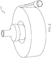
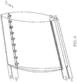
FIGS. 2-4 depict various views of one exemplary embodiment of a contactor-separator that may be used to implement the system ofFIG. 1 ; -
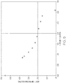
FIG. 5 graphically depicts one example of how pump discharge pressure varies with inert gas flow into the pump; -
FIG 6 depicts a cross-section side view of one embodiment of a centrifugal pump impeller; -
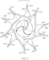
FIG. 7 depicts an end view of another embodiment of a centrifugal pump impeller; and -
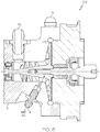
FIG. 8 depicts a cross-section side view of a portion of a centrifugal pump. - The following detailed description is merely exemplary in nature and is not intended to limit the invention or the application and uses of the invention. As used herein, the word "exemplary" means "serving as an example, instance, or illustration." Thus, any embodiment described herein as "exemplary" is not necessarily to be construed as preferred or advantageous over other embodiments. All of the embodiments described herein are exemplary embodiments provided to enable persons skilled in the art to make or use the invention and not to limit the scope of the invention which is defined by the claims. Furthermore, there is no intention to be bound by any expressed or implied theory presented in the preceding technical field, background, brief summary, or the following detailed description.
- Referring now to
FIG. 1 , a simplified schematic representation of only a portion of one embodiment of a gas turbine engine fuelflow control system 100 is depicted. The depictedsystem 100 includes an integrated fuel deoxygenation system, and may be operated in either a non-deoxygenation mode or a deoxygenation mode. In the non-deoxygenation mode, thesystem 100 operates as a conventional fuel flow control system. In the deoxygenation mode, however, thesystem 100 implements the functions of both a fuel deoxygenation system and a conventional fuel flow control system. The depictedsystem 100 includes at least aboost pump 102, a contactor-separator 104, afuel source 106, aninert gas source 108, and acontrol 110. - The
boost pump 102 is coupled to receive a drive torque from a non-illustrated torque source, such as a motor or a gas turbine engine. Theboost pump 102 is configured, upon receipt of the drive torque, to receive fluid either from only thefuel source 106 or from both thefuel source 106 and theinert gas source 108, and discharge fluid therefrom. When thesystem 100 is operating in the non-deoxygenation mode, theboost pump 102 is configured to operate as a fuel pump. As such, theboost pump 102 only receives fuel from thefuel source 106, and discharges the fuel. When the system is operating in the deoxygenation mode, theboost pump 102 is configured to operate as a fuel-gas mixer. As such, theboost pump 102 receives fuel from thefuel source 106 and inert gas from theinert gas source 108, uniformly and intimately mixes the fuel and inert gas, and discharges a fuel/gas mixture. A more detailed description of theboost pump 102, and how it is configured to function as either a fuel pump or a fuel-gas mixer, will be provided further below. Before doing so, however, various other of the components depicted inFIG. 1 will be described. - The contactor-
separator 104 is coupled to receive the fluid that is discharged from theboost pump 102. As noted above, when thesystem 100 is operating in the non-deoxygenation mode, the fluid that is discharged from theboost pump 104 is only fuel. In this mode, the fuel supplied from theboost pump 102 merely flows into the contactor-separator 104 and is supplied to other non-illustrated downstream components. However, when thesystem 100 is operating in the deoxygenation mode, the fluid that is discharged from theboost pump 102 is a fuel/gas mixture. In this mode, the contactor-separator 104 implements the functions of both a contactor and a separator. - It will be appreciated that the contactor-
separator 104 may be variously configured and implemented, but is preferably a passive device. In one embodiment, the passive contactor-separator 104 is configured and implemented using any one of the numerous passive contactor-separators 104 described in co-pendingU.S. Patent Application No. 14/539,279, filed November 12, 2014 U.S. Patent Application No. 14/570,152, filed December 15, 2014 separators 104 described in these applications are depicted herein inFIGS. 2-4 . - It will additionally be appreciated that the
fuel source 106 and theinert gas source 108 may be variously configured and implemented. In the depicted embodiment, thefuel source 106 is preferably an onboard aircraft fuel tank that receives and stores fuel for use by various fuel-consuming loads, such as a gas turbine engine. Theinert gas source 108 may be a stand-alone source of inert gas, such as an inert gas storage tank or one or more inert gas bottles. Alternatively, theinert gas source 108 may be an inert gas generating system that generates inert gas from, for example, engine bleed air that is selectively supplied from a non-illustrated gas turbine engine. Some non-limiting examples of such systems include one or more of an on-board inert gas generating system (OBIGGS), a pressure swing adsorption (PSA) system, a catalytic reactor, a plurality of membranes, just to name a few. It will be appreciated that the inert gas is preferably nitrogen (N2), but may be one of the other inert gasses. - Before proceeding further, it is noted that the fuel
flow control system 100 may, in some embodiments, include one or more other components between theboost pump 102 and the contactor-separator 104. The understanding of these additional components, if included, is not needed to describe or enable thesystem 100 and will, therefore, not be depicted or described. - Returning once again to
FIG. 1 , a more detailed description of theboost pump 102, and how it is configured to function as either a fuel pump or a fuel-gas mixer will now be provided. Preferably, theboost pump 102 is implemented as a centrifugal pump, and includes apump housing 111 and animpeller 113 that is rotationally mounted within thepump housing 111. Thepump housing 111 includes afuel inlet 112, agas inlet 114, and anoutlet 116. Thefuel inlet 112 is in fluid communication with thefuel source 106, and theoutlet 116 is in fluid communication with the contactor-separator 104. Agas inlet valve 118 is disposed upstream of thegas inlet 114, and is responsive to valve position commands to move between a closed position and a plurality of open position. In the closed position, inert gas is prevented from flowing from theinert gas source 108 into thegas inlet 114. Conversely, in any one of the plurality of open positions, inert gas from theinert gas source 108 may flow into thegas inlet 114. - The
control 110 is coupled to, and is configured to supply the valve commands to, thegas inlet valve 118. Thecontrol 110 thus commands thegas inlet valve 118 to selectively move to the closed position or one of the open positions. When thegas inlet valve 118 is in the closed position, thesystem 100 is operating in the non-deoxygenation mode and theboost pump 102 is configured to operate as a fuel pump. As may thus be appreciated, in the non-deoxygenation mode theboost pump 102 is configured, upon receipt of the drive torque, to rotate and draw fuel into thefuel inlet 112 and discharge only fuel from theoutlet 116. When thegas inlet valve 118 is in an open position, thesystem 100 is operating in the deoxygenation mode and theboost pump 102 is configured to operate as a fuel-gas mixer. Thus, in the deoxygenation mode theboost pump 102 is configured, upon receipt of the drive torque, to rotate and draw fuel into thefuel inlet 112 and to receive inert gas injected into thegas inlet 114. Theboost pump 102 is further configured to mix the fuel and inert gas to produce a fuel-gas mixture, and to discharge the fuel-gas mixture from theoutlet 116. - As may be readily appreciated, the discharge pressure at the
outlet 116 of theboost pump 102 will vary with inert gas flow into thegas inlet 114. According to the invention, thecontrol 110 is also configured to supply valve commands to modulate the position of thegas inlet valve 118, to thereby control the flow of inert gas into thegas inlet 114, and thus the discharge pressure at theoutlet 116 of theboost pump 102. For completeness, one example of the variation in boost pump discharge pressure at theoutlet 116 with inert gas flow into thegas inlet 114 is depicted graphically inFIG. 5 . It will be appreciated that this is merely exemplary of one particular centrifugal pump, and may vary with other pumps. It will additionally be appreciated that pump discharge pressure versus inert gas flow into the pump will vary depending upon the particular location at which the inert gas is injected into theboost pump 102. - It will additionally be appreciated that the
control 110 may be configured to control the position of thegas inlet valve 118, and thus inert gas flow into thegas inlet 114, using any one of numerous control schemes. In this regard, thecontrol 110 may be configured to implement a closed-loop feedback control scheme, in which one ormore sensors 122 sense a parameter and supply feedback signals to thecontrol 110. Thesensors 122, if included, may vary, and may include one or more of an inert gas flow sensor, a discharge pressure sensor, or both, just to name a few. In other embodiments, thecontrol 110 may be configured to implement a predetermined schedule of boost pump discharge pressure vs. gas inlet valve position. - Regardless of the particular control scheme that is used, the
boost pump 102, and more specifically thegas inlet 114, is preferably configured such that the inert gas that is supplied thereto is discharged into theboost pump 102 between thefuel inlet 112 and theoutlet 116. Most preferably, and asFIG. 1 further depicts, theimpeller 113 is disposed downstream of thegas inlet 114 so that the inert gas is discharged into the boost pump upstream of theimpeller 113. It will be appreciated that this may be accomplished using any one of numerous techniques. Three non-limiting techniques are depicted inFIGS. 6-8 , and will now be briefly described. - Referring first to
FIG. 6 , a cross-section side view of one embodiment of animpeller 113 is depicted. In this embodiment, theimpeller 113 is formed on animpeller shaft 601, and includes acentral section 602 and a plurality ofimpeller blades 604. Eachimpeller blade 604 extends radially away from thecentral section 602 and, as shown more clearly inFIG. 7 , includes aleading edge 606 and a trailingedge 608. - The
impeller shaft 601 has anouter surface 612 and acentral bore 614 formed therein. Theimpeller shaft 601 is adapted to receive the drive torque from the drive torque source. As such, it is adapted to couple to a drive shaft that extends from the drive torque source. In the depicted embodiment, aninducer 616 is also formed on theimpeller shaft 601, and is disposed upstream of theimpeller 113. - As
FIG. 6 additionally depicts, a plurality ofgas flow channels 618 are formed in theimpeller shaft 601 between thecentral bore 614 and theouter surface 612. Eachgas flow channel 618 is disposed between theinducer 616 and theimpeller 113 and is in fluid communication with the gas inlet 114 (not depicted inFIG. 6 ). Preferably, thegas flow channels 618 are disposed near the root of theimpeller 113. As such, and asarrows 622 illustrate, when thegas inlet valve 118 is open, inert gas from thegas inlet 114 is directed into thecentral bore 614, and is discharged from eachgas flow channel 618 just upstream of theimpeller 113. - Referring now to
FIG. 7 , which is an end view of theimpeller 113, in this embodiment, in addition to or instead of thegas flow channels 618 depicted inFIG. 6 , a plurality ofinternal channels 702 are formed in theimpeller 113. Each of thesechannels 702 is in fluid communication with the gas inlet 114 (not depicted inFIG. 7 ). Eachchannel 702 also extends between thecentral section 602 of theimpeller 113 and a trailingedge 608 of a different one of theimpeller blades 604. - The third non-limiting technique is depicted in
FIG. 8 , which depicts a cross-section side view of a portion of theboost pump 102. With this technique, thegas inlet 114 is formed solely in thepump housing 111 and is configured to inject inert gas upstream of theimpeller 113, and preferably near the root of theimpeller 113, where pressure is at a minimum. - Regardless of the technique that is employed to inject the inert gas, the
system 100 described herein may be selectively operated in either a non-deoxygenation mode or a deoxygenation mode. In the deoxygenation mode,boost pump 102 mixes the fuel with inert gas and the pressure rise across theboost pump 102 is controllably reduced. These two functions are performed by forcing the inert gas directly into theboost pump 102, thus reducing its efficiency while using the rotary mixing capability of theimpeller 113. - While at least one exemplary embodiment has been presented in the foregoing detailed description of the invention, it should be appreciated that a vast number of variations exist. It should also be appreciated that the exemplary embodiment or exemplary embodiments are only examples, and are not intended to limit the scope, applicability, or configuration of the invention in any way. Rather, the foregoing detailed description will provide those skilled in the art with a convenient road map for implementing an exemplary embodiment of the invention. It being understood that various changes may be made in the function and arrangement of elements described in an exemplary embodiment without departing from the scope of the invention as set forth in the appended claims.
Claims (6)
- A fuel flow control system, comprising:a centrifugal pump (102) having a fuel inlet (112), a gas inlet (114), and an outlet (116);the fuel control system being characterised in that it further comprises:a gas inlet valve (118) disposed upstream of the gas inlet and responsive to valve position commands to move between a closed position, in which inert gas is prevented from flowing into the gas inlet, and a plurality of open positions, in which inert gas may flow into the gas inlet; anda control (110) coupled to the gas inlet valve and configured to supply the valve position commands to the gas inlet valve (118) to command the gas inlet valve to selectively move to the closed position or one of the plurality of open positions, the fuel control system being further characterised in that:in the closed position, the centrifugal pump is configured to operate as a fuel pump,in any one of the open positions, the centrifugal pump is configured to operate as a fuel-gas mixer,discharge pressure at the outlet of the centrifugal pump varies with inert gas flow into the gas inlet, andthe control is further configured to supply the valve commands to the gas inlet valve to thereby control the discharge pressure at the outlet of the centrifugal pump.
- The system of claim 1, wherein the centrifugal pump (102) is adapted to receive a drive torque and is configured, upon receipt thereof, to draw fuel into the fuel inlet (112) and:(i) when the gas inlet valve (118) is in the closed position, to discharge only fuel from the outlet, and(ii) when the gas inlet valve is in any one of the open positions, to receive inert gas injected into the gas inlet, mix the fuel and inert gas to produce a fuel-gas mixture, and discharge the fuel-gas mixture from the outlet.
- The system of claim 1, wherein the gas inlet (114) is configured such that inert gas supplied thereto is discharged into the centrifugal pump (102) between the fuel inlet and the outlet.
- The system of claim 1, wherein the centrifugal pump (102) comprises:an impeller (113) including a central section (602) and a plurality of impeller blades (604) that extend radially away from the central section, each impeller blade including a leading edge (606) and a trailing edge (608); anda plurality of internal channels (702) formed in the impeller, each channel being in fluid communication with the gas inlet (114) and extending between the central section and a trailing edge of a different one of the impeller blades.
- The system of claim 1, wherein the centrifugal pump (102) comprises:an impeller shaft (601) having a central bore (614) formed therein and an outer surface (612), the impeller shaft being adapted to couple to a drive shaft;an impeller formed on the impeller shaft;an inducer (616) formed on the impeller shaft and disposed upstream of the impeller; anda plurality of gas flow channels (618) formed in the impeller shaft and extending between the central bore and the outer surface, each gas flow channel being disposed between the inducer and the impeller and in fluid communication with the gas inlet.
- The system of claim 1, wherein the centrifugal pump (102) comprises:a pump housing (111) having the gas inlet (114) formed therein; andan impeller (113) rotationally mounted within the pump housing, the impeller being disposed downstream of the gas inlet.
Applications Claiming Priority (1)
| Application Number | Priority Date | Filing Date | Title |
|---|---|---|---|
| US14/597,938 US9897054B2 (en) | 2015-01-15 | 2015-01-15 | Centrifugal fuel pump with variable pressure control |
Publications (2)
| Publication Number | Publication Date |
|---|---|
| EP3045734A1 EP3045734A1 (en) | 2016-07-20 |
| EP3045734B1 true EP3045734B1 (en) | 2019-06-26 |
Family
ID=55085569
Family Applications (1)
| Application Number | Title | Priority Date | Filing Date |
|---|---|---|---|
| EP16150501.1A Active EP3045734B1 (en) | 2015-01-15 | 2016-01-07 | Centrifugal fuel pump with an auxiliary inlet for the injection of inert gas and with a valve regulating the gas flow |
Country Status (2)
| Country | Link |
|---|---|
| US (1) | US9897054B2 (en) |
| EP (1) | EP3045734B1 (en) |
Families Citing this family (27)
| Publication number | Priority date | Publication date | Assignee | Title |
|---|---|---|---|---|
| CN110077605A (en) * | 2018-01-26 | 2019-08-02 | 哈米尔顿森德斯特兰德公司 | The fuel tank of aircraft is catalyzed inerting equipment |
| CN110092001A (en) * | 2018-01-29 | 2019-08-06 | 哈米尔顿森德斯特兰德公司 | The fuel tank of aircraft is catalyzed inerting equipment |
| US11420763B2 (en) | 2018-11-02 | 2022-08-23 | General Electric Company | Fuel delivery system having a fuel oxygen reduction unit |
| US11085636B2 (en) | 2018-11-02 | 2021-08-10 | General Electric Company | Fuel oxygen conversion unit |
| US11186382B2 (en) | 2018-11-02 | 2021-11-30 | General Electric Company | Fuel oxygen conversion unit |
| US11148824B2 (en) | 2018-11-02 | 2021-10-19 | General Electric Company | Fuel delivery system having a fuel oxygen reduction unit |
| US11577852B2 (en) * | 2018-11-02 | 2023-02-14 | General Electric Company | Fuel oxygen conversion unit |
| US11131256B2 (en) | 2018-11-02 | 2021-09-28 | General Electric Company | Fuel oxygen conversion unit with a fuel/gas separator |
| US11319085B2 (en) | 2018-11-02 | 2022-05-03 | General Electric Company | Fuel oxygen conversion unit with valve control |
| US11447263B2 (en) | 2018-11-02 | 2022-09-20 | General Electric Company | Fuel oxygen reduction unit control system |
| US11161622B2 (en) | 2018-11-02 | 2021-11-02 | General Electric Company | Fuel oxygen reduction unit |
| US11193671B2 (en) | 2018-11-02 | 2021-12-07 | General Electric Company | Fuel oxygen conversion unit with a fuel gas separator |
| US11851204B2 (en) | 2018-11-02 | 2023-12-26 | General Electric Company | Fuel oxygen conversion unit with a dual separator pump |
| US11015534B2 (en) | 2018-11-28 | 2021-05-25 | General Electric Company | Thermal management system |
| US11391211B2 (en) | 2018-11-28 | 2022-07-19 | General Electric Company | Waste heat recovery system |
| US11186383B2 (en) * | 2019-04-02 | 2021-11-30 | Hamilton Sundstrand Corporation | Centrifugal fuel pump ice prevention |
| US10914274B1 (en) | 2019-09-11 | 2021-02-09 | General Electric Company | Fuel oxygen reduction unit with plasma reactor |
| US11774427B2 (en) | 2019-11-27 | 2023-10-03 | General Electric Company | Methods and apparatus for monitoring health of fuel oxygen conversion unit |
| US11773776B2 (en) | 2020-05-01 | 2023-10-03 | General Electric Company | Fuel oxygen reduction unit for prescribed operating conditions |
| US11866182B2 (en) | 2020-05-01 | 2024-01-09 | General Electric Company | Fuel delivery system having a fuel oxygen reduction unit |
| US11906163B2 (en) | 2020-05-01 | 2024-02-20 | General Electric Company | Fuel oxygen conversion unit with integrated water removal |
| US11434824B2 (en) | 2021-02-03 | 2022-09-06 | General Electric Company | Fuel heater and energy conversion system |
| US11591965B2 (en) | 2021-03-29 | 2023-02-28 | General Electric Company | Thermal management system for transferring heat between fluids |
| US12139270B2 (en) | 2021-04-19 | 2024-11-12 | General Electric Company | Aircraft thermal transport system and method |
| US12115470B2 (en) | 2021-04-27 | 2024-10-15 | General Electric Company | Fuel oxygen reduction unit |
| US12005377B2 (en) | 2021-06-15 | 2024-06-11 | General Electric Company | Fuel oxygen reduction unit with level control device |
| US11542870B1 (en) | 2021-11-24 | 2023-01-03 | General Electric Company | Gas supply system |
Citations (1)
| Publication number | Priority date | Publication date | Assignee | Title |
|---|---|---|---|---|
| EP1553306A1 (en) * | 2002-07-25 | 2005-07-13 | Yonehara Giken Co., Ltd. | Mix-in structure for gas or the like in pressurization centrifugal pump |
Family Cites Families (65)
| Publication number | Priority date | Publication date | Assignee | Title |
|---|---|---|---|---|
| US2575568A (en) | 1946-11-12 | 1951-11-20 | Gulf Research Development Co | Centrifugal gas-liquid separator |
| GB735866A (en) | 1952-02-15 | 1955-08-31 | Rolls Royce | Improvements in or relating to fuel pumps and systems |
| US3233389A (en) | 1962-10-29 | 1966-02-08 | Exxon Research Engineering Co | Axial-flow centrifugal vapor-liquid contacting and separating device and method |
| US3663117A (en) * | 1970-01-21 | 1972-05-16 | Cornell Mfg Co | Aeration pump |
| US3691730A (en) | 1971-05-18 | 1972-09-19 | Parker Hannifin Corp | Fuel tank inerting system |
| US3847298A (en) | 1972-03-20 | 1974-11-12 | Garrett Corp | Fuel tank inerting system |
| US3788039A (en) | 1972-08-24 | 1974-01-29 | Parker Hannifin Corp | Fuel tank inerting system with means to improve thermal stability of fuel |
| US3948626A (en) | 1974-10-25 | 1976-04-06 | Parker-Hannifin Corporation | Refueling equipment for aircraft fuel tanks and the like |
| US4017276A (en) | 1976-06-22 | 1977-04-12 | The Lummus Company | Deoxygenation of water |
| US4190030A (en) * | 1977-12-21 | 1980-02-26 | Chester Jerry D | Carburation system |
| US4895683A (en) | 1987-04-27 | 1990-01-23 | Kiyomoto Tekko Kabushiki Kaisha | Apparatus for mass transferring between phases different from each other |
| SE466360B (en) | 1987-09-03 | 1992-02-03 | Scanpump Abs Ab | CENTRIFUGAL PUMP WHEEL AND SET ON PUMPING A FLUID CONTAINING GAS, MEANS OF A CENTRIFUGAL PUMP |
| US4890980A (en) * | 1988-08-08 | 1990-01-02 | Ingersoll-Rand Company | Centrifugal pump |
| US5061151A (en) * | 1990-02-22 | 1991-10-29 | Sundstrand Corporation | Centrifugal pump system with liquid ring priming pump |
| US5405497A (en) | 1990-08-28 | 1995-04-11 | Kamyr, Inc. | Method of chemically reacting a liquid with a gas in a vortex |
| US5112357A (en) | 1990-10-05 | 1992-05-12 | Universal Beverage Equipment, Inc. | Deoxygenation system and method |
| US5207734A (en) | 1991-07-22 | 1993-05-04 | Corning Incorporated | Engine exhaust system for reduction of hydrocarbon emissions |
| CA2073908A1 (en) | 1992-07-16 | 1994-01-17 | Mark W. Kennedy | Rotary gas injector |
| US5316682A (en) | 1993-03-25 | 1994-05-31 | Key Solutions, Inc. | Gas micronizer and purification system and related methods |
| KR950005348A (en) | 1993-08-16 | 1995-03-20 | 조안 엠. 젤사 | Apparatus and method for stripping volatile components from liquids |
| JPH0760005A (en) | 1993-08-31 | 1995-03-07 | Miura Co Ltd | How to degas liquid products |
| US5531904A (en) | 1995-03-20 | 1996-07-02 | Revtech Industries, Inc. | Gas sparging method for removing volatile contaminants from liquids |
| US5529701A (en) | 1995-03-20 | 1996-06-25 | Revtech Industries, Inc. | Method and apparatus for optimizing gas-liquid interfacial contact |
| US5662811A (en) | 1995-03-20 | 1997-09-02 | Revtech Industries, Inc. | Method for creating gas-liquid interfacial contact conditions for highly efficient mass transfer |
| US6004386A (en) | 1995-06-21 | 1999-12-21 | Revtech Industries, Inc. | Apparatus for creating gas-liquid interfacial contact conditions for highly efficient mass transfer |
| US5858283A (en) | 1996-11-18 | 1999-01-12 | Burris; William Alan | Sparger |
| US5863031A (en) | 1997-05-14 | 1999-01-26 | Ferro Corporation | Ceramic diffuser assembly |
| US6053249A (en) | 1998-05-05 | 2000-04-25 | Atlantic Richfield Company | Method and apparatus for injecting gas into a subterranean formation |
| EP1077079B1 (en) | 1999-08-18 | 2014-05-21 | Tsukishima Kankyo Engineering Ltd. | Gas-liquid contacting column apparatus and use thereof |
| US6431528B1 (en) | 1999-10-07 | 2002-08-13 | Hisao Kojima | Apparatus for removing impurities in liquid |
| US6315815B1 (en) | 1999-12-16 | 2001-11-13 | United Technologies Corporation | Membrane based fuel deoxygenator |
| AU2002214553A1 (en) | 2000-10-02 | 2002-04-15 | Beers Karl | Aircraft fuel tank inerting |
| WO2002081382A1 (en) | 2001-04-05 | 2002-10-17 | Petreco International, Inc. | Mechanical oxygen scavenger device |
| US7819275B2 (en) | 2001-07-03 | 2010-10-26 | Container Development, Ltd. | Can shell and double-seamed can end |
| EP1427519B1 (en) | 2001-09-17 | 2006-05-31 | Fibra Limited | A device and a method for contacting a liquid with a gas |
| JP2004011933A (en) | 2002-06-03 | 2004-01-15 | Nissan Motor Co Ltd | Combustor, fuel reformer, and fuel cell system |
| US6830608B1 (en) | 2002-06-28 | 2004-12-14 | Jaeco Technology, Inc. | Apparatus for contacting large volumes of gas and liquid across microscopic interfaces |
| KR100531128B1 (en) | 2002-09-26 | 2005-11-28 | 한국화학연구원 | A method for preparing dimethylether using membrane reactor with separation and reaction |
| US6939392B2 (en) | 2003-04-04 | 2005-09-06 | United Technologies Corporation | System and method for thermal management |
| US6709492B1 (en) | 2003-04-04 | 2004-03-23 | United Technologies Corporation | Planar membrane deoxygenator |
| EP1673156A2 (en) | 2003-10-24 | 2006-06-28 | Cleveland Gas Systems Llc | Spinning impingement multiphase contacting device |
| US7264655B2 (en) | 2003-12-03 | 2007-09-04 | Single Buoy Moorings, Inc. | Gas/liquid separation in water injection into hydrocarbon reservoir |
| US7260926B2 (en) | 2004-01-20 | 2007-08-28 | United Technologies Corporation | Thermal management system for an aircraft |
| US7093437B2 (en) | 2004-01-29 | 2006-08-22 | United Technologies Corporation | Extended operability aircraft fuel delivery system |
| US7153343B2 (en) | 2004-03-24 | 2006-12-26 | United Technologies Corporation | Fuel deoxygenation system |
| US20050274649A1 (en) | 2004-06-09 | 2005-12-15 | Spadaccini Louis J | Method for suppressing oxidative coke formation in liquid hydrocarbons containing metal |
| US7186328B1 (en) | 2004-09-29 | 2007-03-06 | Uop Llc | Process for the regeneration of an adsorbent bed containing sulfur oxidated compounds |
| CA2589897A1 (en) | 2004-11-30 | 2006-08-17 | Phyre Technologies, Inc. | Contacting systems and methods and uses thereof |
| US7459081B2 (en) | 2004-11-30 | 2008-12-02 | Phyre Technologies, Inc. | Contacting systems and methods and uses thereof |
| US7465335B2 (en) | 2005-02-02 | 2008-12-16 | United Technologies Corporation | Fuel deoxygenation system with textured oxygen permeable membrane |
| US7465336B2 (en) | 2005-06-09 | 2008-12-16 | United Technologies Corporation | Fuel deoxygenation system with non-planar plate members |
| US7892321B2 (en) | 2006-02-01 | 2011-02-22 | Intelligent Energy, Inc. | Integrated heated prevaporation module |
| CN101415803B (en) | 2006-04-04 | 2012-10-24 | 大阳日酸株式会社 | Method for separating methane, methane separator and methane utilization system |
| EP1958691A1 (en) | 2007-02-15 | 2008-08-20 | Uop Llc | A process for the regeneration of an absorbent bed containing sulfur oxidated compounds |
| US7896232B1 (en) | 2007-11-06 | 2011-03-01 | United Services Automobile Association (Usaa) | Systems, methods, and apparatus for receiving images of one or more checks |
| US7806966B2 (en) | 2007-12-27 | 2010-10-05 | Bose Ranendra K | Nitrogen inerting system for explosion prevention in aircraft fuel tank and oxygenating system for improving combustion efficiency of aerospace rockets/ aircraft engines |
| US8221070B2 (en) * | 2009-03-25 | 2012-07-17 | Woodward, Inc. | Centrifugal impeller with controlled force balance |
| CA2781361A1 (en) | 2009-12-04 | 2011-06-09 | Exxonmobil Research And Engineering Company | Method for increasing color quality and stability of fuel field of the invention |
| US8602362B2 (en) | 2010-10-08 | 2013-12-10 | Simmonds Precision Products, Inc. | System and method for scavenging ullage from center wing tanks in an airplane |
| US8388740B2 (en) | 2010-10-27 | 2013-03-05 | Uop Llc | Simplified process to remove dissolved oxygen from hydrocarbon streams |
| US8449656B2 (en) | 2010-11-16 | 2013-05-28 | Amt International Inc. | Process and apparatus for removal of oxygen from seawater |
| US9028675B2 (en) | 2011-07-07 | 2015-05-12 | Exxonmobil Research And Engineering Company | Method for increasing thermal stability of a fuel composition using a solid phosphoric acid catalyst |
| WO2013110950A1 (en) | 2012-01-25 | 2013-08-01 | Acal Energy Limited | Improved fuel cell electrolyte regenerator and separator |
| US9334109B1 (en) * | 2012-02-02 | 2016-05-10 | EcoVapor Recovery Systems, LLC | Vapor recovery systems and methods utilizing selective recirculation of recovered gases |
| EP2631281A3 (en) | 2012-02-27 | 2013-09-18 | Rolls-Royce plc | An apparatus and method for conditioning a hydrocarbon fuel containing oxygen |
-
2015
- 2015-01-15 US US14/597,938 patent/US9897054B2/en not_active Expired - Fee Related
-
2016
- 2016-01-07 EP EP16150501.1A patent/EP3045734B1/en active Active
Patent Citations (1)
| Publication number | Priority date | Publication date | Assignee | Title |
|---|---|---|---|---|
| EP1553306A1 (en) * | 2002-07-25 | 2005-07-13 | Yonehara Giken Co., Ltd. | Mix-in structure for gas or the like in pressurization centrifugal pump |
Also Published As
| Publication number | Publication date |
|---|---|
| US9897054B2 (en) | 2018-02-20 |
| EP3045734A1 (en) | 2016-07-20 |
| US20160208759A1 (en) | 2016-07-21 |
Similar Documents
| Publication | Publication Date | Title |
|---|---|---|
| US9897054B2 (en) | Centrifugal fuel pump with variable pressure control | |
| US9897100B2 (en) | In-line continuous flow liquid-gas separator-pump | |
| US11828223B2 (en) | Variable jet pump | |
| EP3034409B1 (en) | Aircraft fuel deoxygenation system | |
| CN112922731B (en) | Motor assistance for multi-shaft turbine operation and control | |
| US9724625B2 (en) | In-line centrifuge-separator pump | |
| EP3473842B1 (en) | Electric cruise pump system | |
| US8127548B2 (en) | Hybrid electrical/mechanical turbine engine fuel supply system | |
| US8286432B2 (en) | Electric power generating turbine engine fuel supply system | |
| EP2959133B1 (en) | Removing non-homogeneous ice from a fuel system | |
| US9885287B2 (en) | Gas turbine engine mechanical-electrical hybrid fuel delivery system | |
| US20180050812A1 (en) | Aircraft fuel pump systems | |
| US11879392B2 (en) | Gas supply system | |
| KR102242938B1 (en) | System and method for the emergency starting of an aircraft turbomachine | |
| EP3036482B1 (en) | Dual fuel nozzle system and apparatus | |
| EP3434904A1 (en) | Hydrocarbon fuel system | |
| US12234840B2 (en) | Jet pump system | |
| US12077279B2 (en) | System and method for detecting and mitigating a propeller failure condition | |
| EP2753811A1 (en) | Fuel system using dual pressure hi-speed centrifugal pump arrangement | |
| EP4607036A1 (en) | Jet pump system | |
| CN119308761A (en) | Fuel oxygen reduction unit for specified operating conditions | |
| CN204082563U (en) | A kind of high anti-cavitation fast self-priming oil pump group | |
| US12115470B2 (en) | Fuel oxygen reduction unit | |
| EP3719325B1 (en) | Centrifugal pump for ice prevention | |
| US20260103287A1 (en) | Power switching system of an anti-ice system for use with a main powersupply and an auxiliary power supply |
Legal Events
| Date | Code | Title | Description |
|---|---|---|---|
| PUAI | Public reference made under article 153(3) epc to a published international application that has entered the european phase |
Free format text: ORIGINAL CODE: 0009012 |
|
| 17P | Request for examination filed |
Effective date: 20160107 |
|
| AK | Designated contracting states |
Kind code of ref document: A1 Designated state(s): AL AT BE BG CH CY CZ DE DK EE ES FI FR GB GR HR HU IE IS IT LI LT LU LV MC MK MT NL NO PL PT RO RS SE SI SK SM TR |
|
| AX | Request for extension of the european patent |
Extension state: BA ME |
|
| GRAP | Despatch of communication of intention to grant a patent |
Free format text: ORIGINAL CODE: EPIDOSNIGR1 |
|
| STAA | Information on the status of an ep patent application or granted ep patent |
Free format text: STATUS: GRANT OF PATENT IS INTENDED |
|
| RIC1 | Information provided on ipc code assigned before grant |
Ipc: F04D 29/22 20060101AFI20190114BHEP Ipc: F04D 31/00 20060101ALI20190114BHEP Ipc: F04D 15/00 20060101ALI20190114BHEP Ipc: B64D 37/34 20060101ALI20190114BHEP |
|
| INTG | Intention to grant announced |
Effective date: 20190205 |
|
| GRAS | Grant fee paid |
Free format text: ORIGINAL CODE: EPIDOSNIGR3 |
|
| GRAA | (expected) grant |
Free format text: ORIGINAL CODE: 0009210 |
|
| STAA | Information on the status of an ep patent application or granted ep patent |
Free format text: STATUS: THE PATENT HAS BEEN GRANTED |
|
| AK | Designated contracting states |
Kind code of ref document: B1 Designated state(s): AL AT BE BG CH CY CZ DE DK EE ES FI FR GB GR HR HU IE IS IT LI LT LU LV MC MK MT NL NO PL PT RO RS SE SI SK SM TR |
|
| REG | Reference to a national code |
Ref country code: GB Ref legal event code: FG4D |
|
| REG | Reference to a national code |
Ref country code: CH Ref legal event code: EP |
|
| REG | Reference to a national code |
Ref country code: AT Ref legal event code: REF Ref document number: 1148602 Country of ref document: AT Kind code of ref document: T Effective date: 20190715 |
|
| REG | Reference to a national code |
Ref country code: DE Ref legal event code: R096 Ref document number: 602016015760 Country of ref document: DE |
|
| REG | Reference to a national code |
Ref country code: IE Ref legal event code: FG4D |
|
| REG | Reference to a national code |
Ref country code: NL Ref legal event code: MP Effective date: 20190626 |
|
| PG25 | Lapsed in a contracting state [announced via postgrant information from national office to epo] |
Ref country code: LT Free format text: LAPSE BECAUSE OF FAILURE TO SUBMIT A TRANSLATION OF THE DESCRIPTION OR TO PAY THE FEE WITHIN THE PRESCRIBED TIME-LIMIT Effective date: 20190626 Ref country code: NO Free format text: LAPSE BECAUSE OF FAILURE TO SUBMIT A TRANSLATION OF THE DESCRIPTION OR TO PAY THE FEE WITHIN THE PRESCRIBED TIME-LIMIT Effective date: 20190926 Ref country code: SE Free format text: LAPSE BECAUSE OF FAILURE TO SUBMIT A TRANSLATION OF THE DESCRIPTION OR TO PAY THE FEE WITHIN THE PRESCRIBED TIME-LIMIT Effective date: 20190626 Ref country code: HR Free format text: LAPSE BECAUSE OF FAILURE TO SUBMIT A TRANSLATION OF THE DESCRIPTION OR TO PAY THE FEE WITHIN THE PRESCRIBED TIME-LIMIT Effective date: 20190626 Ref country code: AL Free format text: LAPSE BECAUSE OF FAILURE TO SUBMIT A TRANSLATION OF THE DESCRIPTION OR TO PAY THE FEE WITHIN THE PRESCRIBED TIME-LIMIT Effective date: 20190626 Ref country code: FI Free format text: LAPSE BECAUSE OF FAILURE TO SUBMIT A TRANSLATION OF THE DESCRIPTION OR TO PAY THE FEE WITHIN THE PRESCRIBED TIME-LIMIT Effective date: 20190626 |
|
| REG | Reference to a national code |
Ref country code: LT Ref legal event code: MG4D |
|
| PG25 | Lapsed in a contracting state [announced via postgrant information from national office to epo] |
Ref country code: BG Free format text: LAPSE BECAUSE OF FAILURE TO SUBMIT A TRANSLATION OF THE DESCRIPTION OR TO PAY THE FEE WITHIN THE PRESCRIBED TIME-LIMIT Effective date: 20190926 Ref country code: GR Free format text: LAPSE BECAUSE OF FAILURE TO SUBMIT A TRANSLATION OF THE DESCRIPTION OR TO PAY THE FEE WITHIN THE PRESCRIBED TIME-LIMIT Effective date: 20190927 Ref country code: RS Free format text: LAPSE BECAUSE OF FAILURE TO SUBMIT A TRANSLATION OF THE DESCRIPTION OR TO PAY THE FEE WITHIN THE PRESCRIBED TIME-LIMIT Effective date: 20190626 Ref country code: LV Free format text: LAPSE BECAUSE OF FAILURE TO SUBMIT A TRANSLATION OF THE DESCRIPTION OR TO PAY THE FEE WITHIN THE PRESCRIBED TIME-LIMIT Effective date: 20190626 |
|
| REG | Reference to a national code |
Ref country code: AT Ref legal event code: MK05 Ref document number: 1148602 Country of ref document: AT Kind code of ref document: T Effective date: 20190626 |
|
| PG25 | Lapsed in a contracting state [announced via postgrant information from national office to epo] |
Ref country code: EE Free format text: LAPSE BECAUSE OF FAILURE TO SUBMIT A TRANSLATION OF THE DESCRIPTION OR TO PAY THE FEE WITHIN THE PRESCRIBED TIME-LIMIT Effective date: 20190626 Ref country code: SK Free format text: LAPSE BECAUSE OF FAILURE TO SUBMIT A TRANSLATION OF THE DESCRIPTION OR TO PAY THE FEE WITHIN THE PRESCRIBED TIME-LIMIT Effective date: 20190626 Ref country code: PT Free format text: LAPSE BECAUSE OF FAILURE TO SUBMIT A TRANSLATION OF THE DESCRIPTION OR TO PAY THE FEE WITHIN THE PRESCRIBED TIME-LIMIT Effective date: 20191028 Ref country code: NL Free format text: LAPSE BECAUSE OF FAILURE TO SUBMIT A TRANSLATION OF THE DESCRIPTION OR TO PAY THE FEE WITHIN THE PRESCRIBED TIME-LIMIT Effective date: 20190626 Ref country code: RO Free format text: LAPSE BECAUSE OF FAILURE TO SUBMIT A TRANSLATION OF THE DESCRIPTION OR TO PAY THE FEE WITHIN THE PRESCRIBED TIME-LIMIT Effective date: 20190626 Ref country code: CZ Free format text: LAPSE BECAUSE OF FAILURE TO SUBMIT A TRANSLATION OF THE DESCRIPTION OR TO PAY THE FEE WITHIN THE PRESCRIBED TIME-LIMIT Effective date: 20190626 Ref country code: AT Free format text: LAPSE BECAUSE OF FAILURE TO SUBMIT A TRANSLATION OF THE DESCRIPTION OR TO PAY THE FEE WITHIN THE PRESCRIBED TIME-LIMIT Effective date: 20190626 |
|
| PG25 | Lapsed in a contracting state [announced via postgrant information from national office to epo] |
Ref country code: SM Free format text: LAPSE BECAUSE OF FAILURE TO SUBMIT A TRANSLATION OF THE DESCRIPTION OR TO PAY THE FEE WITHIN THE PRESCRIBED TIME-LIMIT Effective date: 20190626 Ref country code: ES Free format text: LAPSE BECAUSE OF FAILURE TO SUBMIT A TRANSLATION OF THE DESCRIPTION OR TO PAY THE FEE WITHIN THE PRESCRIBED TIME-LIMIT Effective date: 20190626 Ref country code: IS Free format text: LAPSE BECAUSE OF FAILURE TO SUBMIT A TRANSLATION OF THE DESCRIPTION OR TO PAY THE FEE WITHIN THE PRESCRIBED TIME-LIMIT Effective date: 20191026 Ref country code: IT Free format text: LAPSE BECAUSE OF FAILURE TO SUBMIT A TRANSLATION OF THE DESCRIPTION OR TO PAY THE FEE WITHIN THE PRESCRIBED TIME-LIMIT Effective date: 20190626 |
|
| PG25 | Lapsed in a contracting state [announced via postgrant information from national office to epo] |
Ref country code: TR Free format text: LAPSE BECAUSE OF FAILURE TO SUBMIT A TRANSLATION OF THE DESCRIPTION OR TO PAY THE FEE WITHIN THE PRESCRIBED TIME-LIMIT Effective date: 20190626 |
|
| PG25 | Lapsed in a contracting state [announced via postgrant information from national office to epo] |
Ref country code: PL Free format text: LAPSE BECAUSE OF FAILURE TO SUBMIT A TRANSLATION OF THE DESCRIPTION OR TO PAY THE FEE WITHIN THE PRESCRIBED TIME-LIMIT Effective date: 20190626 Ref country code: DK Free format text: LAPSE BECAUSE OF FAILURE TO SUBMIT A TRANSLATION OF THE DESCRIPTION OR TO PAY THE FEE WITHIN THE PRESCRIBED TIME-LIMIT Effective date: 20190626 |
|
| PG25 | Lapsed in a contracting state [announced via postgrant information from national office to epo] |
Ref country code: IS Free format text: LAPSE BECAUSE OF FAILURE TO SUBMIT A TRANSLATION OF THE DESCRIPTION OR TO PAY THE FEE WITHIN THE PRESCRIBED TIME-LIMIT Effective date: 20200224 |
|
| REG | Reference to a national code |
Ref country code: DE Ref legal event code: R097 Ref document number: 602016015760 Country of ref document: DE |
|
| PLBE | No opposition filed within time limit |
Free format text: ORIGINAL CODE: 0009261 |
|
| STAA | Information on the status of an ep patent application or granted ep patent |
Free format text: STATUS: NO OPPOSITION FILED WITHIN TIME LIMIT |
|
| PG2D | Information on lapse in contracting state deleted |
Ref country code: IS |
|
| 26N | No opposition filed |
Effective date: 20200603 |
|
| PG25 | Lapsed in a contracting state [announced via postgrant information from national office to epo] |
Ref country code: SI Free format text: LAPSE BECAUSE OF FAILURE TO SUBMIT A TRANSLATION OF THE DESCRIPTION OR TO PAY THE FEE WITHIN THE PRESCRIBED TIME-LIMIT Effective date: 20190626 Ref country code: MC Free format text: LAPSE BECAUSE OF FAILURE TO SUBMIT A TRANSLATION OF THE DESCRIPTION OR TO PAY THE FEE WITHIN THE PRESCRIBED TIME-LIMIT Effective date: 20190626 |
|
| REG | Reference to a national code |
Ref country code: CH Ref legal event code: PL |
|
| REG | Reference to a national code |
Ref country code: BE Ref legal event code: MM Effective date: 20200131 |
|
| PG25 | Lapsed in a contracting state [announced via postgrant information from national office to epo] |
Ref country code: FR Free format text: LAPSE BECAUSE OF NON-PAYMENT OF DUE FEES Effective date: 20200131 Ref country code: LU Free format text: LAPSE BECAUSE OF NON-PAYMENT OF DUE FEES Effective date: 20200107 |
|
| PG25 | Lapsed in a contracting state [announced via postgrant information from national office to epo] |
Ref country code: BE Free format text: LAPSE BECAUSE OF NON-PAYMENT OF DUE FEES Effective date: 20200131 Ref country code: LI Free format text: LAPSE BECAUSE OF NON-PAYMENT OF DUE FEES Effective date: 20200131 Ref country code: CH Free format text: LAPSE BECAUSE OF NON-PAYMENT OF DUE FEES Effective date: 20200131 |
|
| PG25 | Lapsed in a contracting state [announced via postgrant information from national office to epo] |
Ref country code: IE Free format text: LAPSE BECAUSE OF NON-PAYMENT OF DUE FEES Effective date: 20200107 |
|
| PG25 | Lapsed in a contracting state [announced via postgrant information from national office to epo] |
Ref country code: MT Free format text: LAPSE BECAUSE OF FAILURE TO SUBMIT A TRANSLATION OF THE DESCRIPTION OR TO PAY THE FEE WITHIN THE PRESCRIBED TIME-LIMIT Effective date: 20190626 Ref country code: CY Free format text: LAPSE BECAUSE OF FAILURE TO SUBMIT A TRANSLATION OF THE DESCRIPTION OR TO PAY THE FEE WITHIN THE PRESCRIBED TIME-LIMIT Effective date: 20190626 |
|
| PG25 | Lapsed in a contracting state [announced via postgrant information from national office to epo] |
Ref country code: MK Free format text: LAPSE BECAUSE OF FAILURE TO SUBMIT A TRANSLATION OF THE DESCRIPTION OR TO PAY THE FEE WITHIN THE PRESCRIBED TIME-LIMIT Effective date: 20190626 |
|
| P01 | Opt-out of the competence of the unified patent court (upc) registered |
Effective date: 20230525 |
|
| PGFP | Annual fee paid to national office [announced via postgrant information from national office to epo] |
Ref country code: DE Payment date: 20250129 Year of fee payment: 10 |
|
| PGFP | Annual fee paid to national office [announced via postgrant information from national office to epo] |
Ref country code: GB Payment date: 20250121 Year of fee payment: 10 |