EP3045708A1 - Oberer bifi-rahmen für einen gasturbinenmotor und verfahren das luftverlust verhindert - Google Patents
Oberer bifi-rahmen für einen gasturbinenmotor und verfahren das luftverlust verhindert Download PDFInfo
- Publication number
- EP3045708A1 EP3045708A1 EP16151755.2A EP16151755A EP3045708A1 EP 3045708 A1 EP3045708 A1 EP 3045708A1 EP 16151755 A EP16151755 A EP 16151755A EP 3045708 A1 EP3045708 A1 EP 3045708A1
- Authority
- EP
- European Patent Office
- Prior art keywords
- seal
- forward fairing
- aft seal
- fairing
- engine
- Prior art date
- Legal status (The legal status is an assumption and is not a legal conclusion. Google has not performed a legal analysis and makes no representation as to the accuracy of the status listed.)
- Granted
Links
Images


Classifications
-
- F—MECHANICAL ENGINEERING; LIGHTING; HEATING; WEAPONS; BLASTING
- F02—COMBUSTION ENGINES; HOT-GAS OR COMBUSTION-PRODUCT ENGINE PLANTS
- F02K—JET-PROPULSION PLANTS
- F02K3/00—Plants including a gas turbine driving a compressor or a ducted fan
- F02K3/02—Plants including a gas turbine driving a compressor or a ducted fan in which part of the working fluid by-passes the turbine and combustion chamber
- F02K3/04—Plants including a gas turbine driving a compressor or a ducted fan in which part of the working fluid by-passes the turbine and combustion chamber the plant including ducted fans, i.e. fans with high volume, low pressure outputs, for augmenting the jet thrust, e.g. of double-flow type
- F02K3/06—Plants including a gas turbine driving a compressor or a ducted fan in which part of the working fluid by-passes the turbine and combustion chamber the plant including ducted fans, i.e. fans with high volume, low pressure outputs, for augmenting the jet thrust, e.g. of double-flow type with front fan
-
- B—PERFORMING OPERATIONS; TRANSPORTING
- B64—AIRCRAFT; AVIATION; COSMONAUTICS
- B64D—EQUIPMENT FOR FITTING IN OR TO AIRCRAFT; FLIGHT SUITS; PARACHUTES; ARRANGEMENT OR MOUNTING OF POWER PLANTS OR PROPULSION TRANSMISSIONS IN AIRCRAFT
- B64D27/00—Arrangement or mounting of power plants in aircraft; Aircraft characterised by the type or position of power plants
- B64D27/02—Aircraft characterised by the type or position of power plants
- B64D27/10—Aircraft characterised by the type or position of power plants of gas-turbine type
- B64D27/12—Aircraft characterised by the type or position of power plants of gas-turbine type within, or attached to, wings
-
- B—PERFORMING OPERATIONS; TRANSPORTING
- B64—AIRCRAFT; AVIATION; COSMONAUTICS
- B64D—EQUIPMENT FOR FITTING IN OR TO AIRCRAFT; FLIGHT SUITS; PARACHUTES; ARRANGEMENT OR MOUNTING OF POWER PLANTS OR PROPULSION TRANSMISSIONS IN AIRCRAFT
- B64D27/00—Arrangement or mounting of power plants in aircraft; Aircraft characterised by the type or position of power plants
- B64D27/40—Arrangements for mounting power plants in aircraft
- B64D27/402—Arrangements for mounting power plants in aircraft comprising box like supporting frames, e.g. pylons or arrangements for embracing the power plant
-
- B—PERFORMING OPERATIONS; TRANSPORTING
- B64—AIRCRAFT; AVIATION; COSMONAUTICS
- B64D—EQUIPMENT FOR FITTING IN OR TO AIRCRAFT; FLIGHT SUITS; PARACHUTES; ARRANGEMENT OR MOUNTING OF POWER PLANTS OR PROPULSION TRANSMISSIONS IN AIRCRAFT
- B64D29/00—Power-plant nacelles, fairings or cowlings
- B64D29/06—Attaching of nacelles, fairings or cowlings
-
- F—MECHANICAL ENGINEERING; LIGHTING; HEATING; WEAPONS; BLASTING
- F02—COMBUSTION ENGINES; HOT-GAS OR COMBUSTION-PRODUCT ENGINE PLANTS
- F02C—GAS-TURBINE PLANTS; AIR INTAKES FOR JET-PROPULSION PLANTS; CONTROLLING FUEL SUPPLY IN AIR-BREATHING JET-PROPULSION PLANTS
- F02C7/00—Features, components parts, details or accessories, not provided for in, or of interest apart form groups F02C1/00 - F02C6/00; Air intakes for jet-propulsion plants
- F02C7/20—Mounting or supporting of plant; Accommodating heat expansion or creep
-
- F—MECHANICAL ENGINEERING; LIGHTING; HEATING; WEAPONS; BLASTING
- F02—COMBUSTION ENGINES; HOT-GAS OR COMBUSTION-PRODUCT ENGINE PLANTS
- F02C—GAS-TURBINE PLANTS; AIR INTAKES FOR JET-PROPULSION PLANTS; CONTROLLING FUEL SUPPLY IN AIR-BREATHING JET-PROPULSION PLANTS
- F02C7/00—Features, components parts, details or accessories, not provided for in, or of interest apart form groups F02C1/00 - F02C6/00; Air intakes for jet-propulsion plants
- F02C7/28—Arrangement of seals
Definitions
- the present disclosures relate generally to a gas turbine engine and, more particularly, to an upper bifi frame for a gas turbine engine.
- a gas turbine engine includes an engine casing that is secured to a pylon of an aircraft.
- a nacelle is positioned around the engine casing.
- a thrust reverser is typically coupled to the engine casing.
- fan flow air through the gas turbine engine needs to be sealed off from the pylon and directed around the nacelle doors.
- An upper bifi frame provides seal lands for sealing the fan flow from the fan, pylon, and core compartments.
- the upper bifi frame may include a cover to prevent fluid accumulation within the gas turbine engine.
- the upper bifi frame may also include silicone seals to allow for increased clearance with nacelle hardware during engine drop.
- the nacelle doors typically open only approximately 45°.
- the upper bifi frame frequently blocks access to the engine casing and other components housed within the nacelle.
- the upper bifi frame often adds difficulty when dropping or raising the engine casing with respect to the pylon.
- known upper bifi frames are required to be entirely removed during engine dropping or raising. This can result in damage to the gas turbine engine.
- an upper bifi frame for preventing air leakage in a gas turbine engine including an engine casing and a fan case.
- the upper bifi frame includes a forward fairing having a forward fairing midsection extending between the engine casing and the fan case.
- the forward fairing has a forward fairing first end including a flange configured to couple to the engine casing.
- the forward fairing has a forward fairing second end extending from the forward fairing midsection and configured to couple to the fan case.
- At least one aft seal is secured to the forward fairing and forms a seal therewith.
- a wedge seal is coupled to the forward fairing and the at least one aft seal and is operative to prevent air leakage to a pylon that is secured to the engine casing.
- the at least one aft seal includes an aft seal midsection extending along the forward fairing midsection and forming a seal therewith.
- An aft seal first end extends along the forward fairing first end and forms a seal therewith.
- An aft seal second end extends along the forward fairing second end and forms a seal therewith.
- the at least one aft seal includes a left aft seal and a right aft seal.
- the left aft seal is coupled to a first side of the forward fairing.
- the right aft seal is coupled to a second side of the forward fairing.
- the at least one aft seal is removable from the forward fairing to allow at least one of raising or dropping the gas turbine engine.
- the gas turbine engine may be at least one of raised or dropped while the forward fairing is joined to the engine casing.
- the at least one aft seal includes a pin operable to secure the at least one aft seal to the forward fairing.
- a bolt is operable to lock the at least one aft seal to the forward fairing.
- the wedge seal provides a seal between a hinge beam of at least one nacelle door and the at least one aft seal.
- the gas turbine engine upper bifi frame forms a fairing for the pylon.
- a gas turbine engine may comprise: an engine casing; a fan case positioned around the engine casing; a pylon attached to the engine casing and operative to secure the engine casing to an aircraft; and an upper bifi frame according to any of the embodiments described above.
- a gas turbine engine having an engine casing, a fan case positioned around the engine casing, and a pylon attached to the engine casing and operative to secure the engine casing to an aircraft.
- An upper bifi frame is provided having a forward fairing coupled between the engine casing and the fan case. At least one aft seal is secured to the forward fairing.
- a wedge seal is coupled to the forward fairing and the at least one aft seal and is operative to prevent air leakage to the pylon.
- the at least one aft seal comprises a left aft seal and a right aft seal.
- the left aft seal is coupled to a first side of the forward fairing.
- the right aft seal is coupled to a second side of the forward fairing.
- the at least one aft seal is removable from the forward fairing to allow at least one of raising or dropping the gas turbine engine while the forward fairing is still secured to the engine casing.
- a pin is operable to secure the at least one aft seal to the forward fairing.
- a bolt is operable to lock the at least one aft seal to the forward fairing.
- the at least one aft seal is removable from the forward fairing to allow access to the engine casing when at least one nacelle door is opened.
- the wedge seal provides a seal between a hinge beam of at least one nacelle door and the at least one aft seal.
- the upper bifi frame forms a fairing for the pylon.
- a method of preventing air leakage in a gas turbine engine having an engine casing, a fan case positioned around the engine casing, at least one nacelle door that encloses a portion of the engine casing, and a pylon to secure the engine casing to an aircraft includes coupling a forward fairing of an upper bifi frame between the engine casing and the fan case.
- the method also includes securing at least one aft seal of the upper bifi frame to the forward fairing.
- the method also includes coupling a wedge seal to the forward fairing and the at least one aft seal.
- the method also includes securing the at least one aft seal to the forward fairing with a pin.
- the method also includes coupling a left aft seal to a first side of the forward fairing; and coupling a right aft seal to a second side of the forward fairing.
- the at least one aft seal is removable from the forward fairing to allow access to the engine casing when the at least one nacelle door is opened.
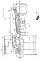
- FIG. 1 shows a gas turbine engine 20, such as a gas turbine used for power generation or propulsion, circumferentially disposed about an engine centerline, or axial centerline axis A.
- the gas turbine engine 20 is disclosed herein as a two-spool turbofan that generally incorporates a fan section 22, a compressor section 24, a combustor section 26 and a turbine section 28.
- Alternative engines might include an augmentor section (not shown) among other systems or features.
- the fan section 22 drives air along a bypass flow path B in a bypass duct, while the compressor section 24 drives air along a core flow path C for compression and communication into the combustor section 26 then expansion through the turbine section 28.
- the exemplary engine 20 generally includes a low speed spool 30 and a high speed spool 32 mounted for rotation about an engine central longitudinal axis A relative to an engine static structure 36 via several bearing systems 38. It should be understood that various bearing systems 38 at various locations may alternatively or additionally be provided, and the location of bearing systems 38 may be varied as appropriate to the application.
- the low speed spool 30 generally includes an inner shaft 40 that interconnects a fan 42, a low pressure compressor 44 and a low pressure turbine 46.
- the inner shaft 40 is connected to the fan 42 through a speed change mechanism, which in exemplary gas turbine engine 20 is illustrated as a geared architecture 48 to drive the fan 42 at a lower speed than the low speed spool 30.
- the high speed spool 32 includes an outer shaft 50 that interconnects a high pressure compressor 52 and high pressure turbine 54.
- a combustor 56 is arranged in exemplary gas turbine 20 between the high pressure compressor 52 and the high pressure turbine 54.
- An engine static structure 36 is arranged generally between the high pressure turbine 54 and the low pressure turbine 46.
- the engine static structure 36 further supports bearing systems 38 in the turbine section 28.
- the inner shaft 40 and the outer shaft 50 are concentric and rotate via bearing systems 38 about the engine central longitudinal axis A which is collinear with their longitudinal axes.
- each of the positions of the fan section 22, compressor section 24, combustor section 26, turbine section 28, and fan drive gear system 48 may be varied.
- gear system 48 may be located aft of combustor section 26 or even aft of turbine section 28, and fan section 22 may be positioned forward or aft of the location of gear system 48.
- the engine 20 in one example is a high-bypass geared aircraft engine.
- the engine 20 bypass ratio is greater than about six (6), with an example embodiment being greater than about ten (10)
- the geared architecture 48 is an epicyclic gear train, such as a planetary gear system or other gear system, with a gear reduction ratio of greater than about 2.3
- the low pressure turbine 46 has a pressure ratio that is greater than about five.
- the engine 20 bypass ratio is greater than about ten (10:1)
- the fan diameter is significantly larger than that of the low pressure compressor 44
- the low pressure turbine 46 has a pressure ratio that is greater than about five 5:1.
- Low pressure turbine 46 pressure ratio is pressure measured prior to inlet of low pressure turbine 46 as related to the pressure at the outlet of the low pressure turbine 46 prior to an exhaust nozzle.
- the geared architecture 48 may be an epicycle gear train, such as a planetary gear system or other gear system, with a gear reduction ratio of greater than about 2.3:1. It should be understood, however, that the above parameters are only exemplary of one embodiment of a geared architecture engine and that the present disclosure is applicable to other gas turbine engines including direct drive turbofans.
- the fan section 22 of the engine 20 is designed for a particular flight condition -- typically cruise at about 0.8 Mach and about 35,000 feet (10,700 meters).
- "Low fan pressure ratio” is the pressure ratio across the fan blade alone, without a Fan Exit Guide Vane (“FEGV”) system.
- the low fan pressure ratio as disclosed herein according to one non-limiting embodiment is less than about 1.45.
- Low corrected fan tip speed is the actual fan tip speed in ft/sec divided by an industry standard temperature correction of [(Tram °R) / (518.7 °R)] 0.5 .
- the "Low corrected fan tip speed” as disclosed herein according to one non-limiting embodiment is less than about 1150 ft / second (350 m/sec).
- the engine 20 is suspended from an engine pylon 66 and mounted within a nacelle 60 through which most of the air pressurized by the fan section 22 bypasses the core engine itself for generating propulsion thrust.
- the fan air is discharged from the engine 20 through a thrust reverser 62.
- Core exhaust gases are discharged from the core engine through a core exhaust nozzle 64.
- the thrust reverser 62 defines a nozzle for discharging the fan air pressurized by the fan section 22.
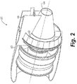
- an upper bifi frame 100 is installed in the engine 20.
- the upper bifi frame 100 is positioned at a trailing edge of a fan flow path generated by the fan section 22.
- the upper bifi frame 100 is positioned downstream from the airfoils 102 (shown in FIGs. 4 and 7 ) of the fan section 22.
- the upper bifi frame 100 is positioned within the engine 20 where the engine 20 transitions to the nacelle 60.
- the upper bifi frame 100 is configured to provide an aerodynamic fairing around the pylon 66 (shown in FIG. 5 ).
- the upper bifi frame 100 includes a forward fairing 110 that is secured to an engine casing 112 at a first end 114.
- a second end 116 of the forward fairing 110 is secured to the fan case 160.
- the forward fairing 110 includes a substantially linear midsection 111 that extends between the first end 114 and the second end 116.
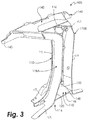
- the first end 114 includes at least one flange 113 extending outward from the midsection 111.
- the at least one flange 113 is secured to the engine casing 112.
- the at least one flange 113 is secured to the engine casing 112 so that the midsection 111 extends upward from the engine casing 112.
- the second end 116 extends substantially perpendicular to the midsection 111. When secured within the engine 20, the second end 116 extends from the midsection 111 toward the fan case 160.
- the second end 116 is secured to the fan case 160 so that the midsection 111 is positioned downstream from the fan case 160.
- At least one aft seal 118 is joined to the forward fairing 110.
- the at least one aft seal 118 is shaped to extend long the contours of the forward fairing 110.
- a midsection 117 of the at least one aft seal 118 extends along the midsection 111 of the forward fairing 110 and creates a seal therewith.
- a first end 119 of the at least one aft seal 118 extends along the first end 114 of the forward fairing 110 and creates a seal therewith.
- a second end 121 of the at least one aft seal 118 extends along the second end 116 of the forward fairing 110 and creates a seal therewith.
- a left aft seal 118A is secured to a first side 120 of the forward fairing 110, and a right aft seal 118B is secured to a second side 122 of the forward fairing 110.
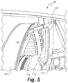
- the aft seal 118 is secured to the forward fairing to seal the engine casing 112 to the thrust reverser 62.
- the at least one aft seal 118 is secured to the forward fairing 110 via a pin and key slot.
- the aft seal 118 includes a cavity 124 for retaining a pin 126.
- the pin 126 is installed in the aft seal 118 during engine installation.
- the pin 126 is secured within the aft seal 118 during manufacture of the aft seal 118.
- the forward fairing 110 includes a key slot 128.
- the key slot 128 includes a wide portion 130 and a narrow portion 132.
- the pin 126 is positioned in the wide portion 130 of the key slot 128 and the aft seal 118 is slid downward so that the pin 126 secures within the narrow portion 132 of the key slot 128.
- the aft portion 118 is secured to the forward portion 110 without having to access a top of the upper bifi frame 100, which can be difficult to access.
- a bolt (not shown) is inserted from below the upper bifi frame 100 to fix the aft seal 118 to the forward fairing 110.
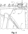
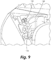
- a wedge seal 140 is secured to the forward fairing 110 and the aft seals 118.
- the wedge seal 140 is secured to the second end 116 of the forward fairing 110 and the corresponding ends of the aft seals 118.
- the wedge seal 140 is secured adjacent to the nacelle 60.
- a cover 142 is positioned over the upper bifi frame 100 to seal the upper bifi frame 100.
- the arrangement of the upper bifi frame 100 allows for raising or lowering the engine 20 from the pylon 66 without having to remove the forward fairing 110.
- the engine With the forward fairing 110 secured to the engine 20 and the nacelle 60, the engine may be raised or lowered without the risk of the engine 20 falling because the engine 20 remains secured during movement.
- a bumper 148 is provided to protect the upper bifi frame forward fairing 110 on its aft end 146 to protect the upper bifi frame forward fairing 110 on its aft end 146 to protect the upper bifi frame forward fairing 110 on its aft end 146 to protect the upper bifi frame forward fairing 110 on its aft end 146, to protect the upper bifi frame forward fairing 110 on its aft end 146, a bumper 148 is provided to withstand clashes with the pylon 66 during engine raise or drop. In particular, the bumper 148 absorbs any impact rather than the forward fairing 110.
- the wedge seal 140 allows clearance through the fan duct 150 to the nacelle 60. Additionally, the wedge seal 140 prevents leakage of air flow from the fan duct 150 to the pylon 66. In one embodiment, a pair of left and right wedge seals 140 fills a gap left by a hinge beam 152 (shown in FIG. 6 ) of the nacelle door 154. In one embodiment, the wedge seals 140 also seal against the hinge beam 152 of the nacelle door 154 (shown in FIG. 6 ). Seals 158 (shown in FIG. 6 ) on the hinge beam 152 seal against the upper bifi frame 100 and transition to the wedge seal 140. These seals 158 eventually transition to the fan case 160.
- the cover 142 allows fluid to flow away from the upper bifi frame 100 to the fan case 160. Pockets within the upper bifi frame are filled with the cover 142. Filling the pockets deflects or directs potential air flow around the upper bifi frame 100.
- the cover 142 is capable of withstanding hydraulic fluid, which is the fluid most likely to accumulate in the upper bifi frame 100.
- the cover 142 is bonded to the upper bifi frame to seal the joint between the cover 142 and the upper bifi frame 100.
- the upper bifi frame provides improved access to the engine 20 when the nacelle door 154 is open.
- the nacelle door 154 typically opens to approximately 45°.
- the upper bifi frame 100 prevents fan flow air from penetrating into the pylon 66, which may cause a loss in engine performance, introduce environment atmosphere into the pylon 66, or cause a breach of the fire containment zone.
- the upper bifi frame 100 design enables removal of only a portion of the upper bifi frame 100 during engine raise to the pylon 66 because the engine 20 can be raised or lowered to or from the pylon 66 without removing the main forward fairing 110. This reduces the installation time for the upper bifi frame 100.
- the bumper 148 provides support to the upper bifi frame 100.
- the cover 142 directs fluid away from pooling areas within the upper bifi frame 100, thereby reducing the area where fluid accumulation may occur.
- the fluid flows to and around the fan case 160 until it reaches the bottom of the engine 20, where the fluid drains from the engine 20 completely.
Landscapes
- Engineering & Computer Science (AREA)
- Chemical & Material Sciences (AREA)
- Combustion & Propulsion (AREA)
- Mechanical Engineering (AREA)
- General Engineering & Computer Science (AREA)
- Aviation & Aerospace Engineering (AREA)
- Structures Of Non-Positive Displacement Pumps (AREA)
Applications Claiming Priority (1)
| Application Number | Priority Date | Filing Date | Title |
|---|---|---|---|
| US14/599,022 US9669938B2 (en) | 2015-01-16 | 2015-01-16 | Upper bifi frame for a gas turbine engine and methods therefor |
Publications (3)
| Publication Number | Publication Date |
|---|---|
| EP3045708A1 true EP3045708A1 (de) | 2016-07-20 |
| EP3045708B1 EP3045708B1 (de) | 2020-12-02 |
| EP3045708B8 EP3045708B8 (de) | 2021-01-20 |
Family
ID=55182225
Family Applications (1)
| Application Number | Title | Priority Date | Filing Date |
|---|---|---|---|
| EP16151755.2A Active EP3045708B8 (de) | 2015-01-16 | 2016-01-18 | Gasturbinenmotor mit einem oberen rahmen und verfahren um luftverlust zu verhindern |
Country Status (2)
| Country | Link |
|---|---|
| US (2) | US9669938B2 (de) |
| EP (1) | EP3045708B8 (de) |
Cited By (1)
| Publication number | Priority date | Publication date | Assignee | Title |
|---|---|---|---|---|
| US20180215477A1 (en) * | 2016-10-14 | 2018-08-02 | Rohr, Inc. | Nacelle bifurcation with leading edge structure |
Families Citing this family (4)
| Publication number | Priority date | Publication date | Assignee | Title |
|---|---|---|---|---|
| US9669938B2 (en) * | 2015-01-16 | 2017-06-06 | United Technologies Corporation | Upper bifi frame for a gas turbine engine and methods therefor |
| US10883385B2 (en) | 2016-08-29 | 2021-01-05 | Raytheon Technologies Corporation | Thermal barrier washer |
| US10697325B2 (en) | 2016-08-29 | 2020-06-30 | Raytheon Technologies Corporation | Thermal barrier seal |
| FR3083213B1 (fr) * | 2018-06-29 | 2020-10-02 | Safran Aircraft Engines | Dispositif de resistance au feu ameliore destine a etre interpose entre une extremite de mat d'accrochage de turbomachine d'aeronef, et un capotage de la turbomachine delimitant un compartiment inter-veine |
Citations (6)
| Publication number | Priority date | Publication date | Assignee | Title |
|---|---|---|---|---|
| US3540682A (en) * | 1964-12-02 | 1970-11-17 | Gen Electric | Turbofan type engine frame and support system |
| GB2401654A (en) * | 2003-05-14 | 2004-11-17 | Rolls Royce Plc | A stator vane assembly for a turbomachine |
| EP2085599A2 (de) * | 2008-01-25 | 2009-08-05 | United Technologies Corporation | Wärmeverwaltungssystem mit geteilter Strömung |
| US20140239083A1 (en) * | 2013-02-22 | 2014-08-28 | United Technologies Corporation | Pivot thrust reverser surrounding inner surface of bypass duct |
| US20140248119A1 (en) * | 2012-10-01 | 2014-09-04 | United Technologies Corporation | Bifurcated Inlet Scoop for Gas Turbine Engine |
| WO2014193515A2 (en) * | 2013-03-14 | 2014-12-04 | United Technologies Corporation | Reverse core engine with thrust reverser |
Family Cites Families (25)
| Publication number | Priority date | Publication date | Assignee | Title |
|---|---|---|---|---|
| US1723763A (en) * | 1927-08-10 | 1929-08-06 | Vincent J Burnelli | Airplane |
| US3848832A (en) * | 1973-03-09 | 1974-11-19 | Boeing Co | Aircraft engine installation |
| US6802479B2 (en) * | 2002-05-16 | 2004-10-12 | The Boeing Company | Flammable fluid line shroud |
| GB2407134B (en) * | 2003-10-16 | 2008-04-16 | Rolls Royce Plc | Aircraft engine mounting assembly |
| FR2885877B1 (fr) * | 2005-05-23 | 2008-12-12 | Airbus France Sas | Mat d'accrochage de turboreacteur pour aeronef |
| US7491253B2 (en) * | 2005-05-31 | 2009-02-17 | Aerospace Filtrations Systems, Inc. | Engine intake system with accessible, interchangeable air filters |
| US7721551B2 (en) | 2006-06-29 | 2010-05-25 | United Technologies Corporation | Fan variable area nozzle for a gas turbine engine fan nacelle |
| WO2008045052A1 (en) * | 2006-10-12 | 2008-04-17 | United Technologies Corporation | Method and device to avoid turbofan instability in a gas turbine engine |
| WO2008045053A2 (en) | 2006-10-12 | 2008-04-17 | United Technologies Corporation | Actuation of a turbofan engine bifurcation to change an effective nozzle exit area |
| US8365513B2 (en) * | 2006-10-12 | 2013-02-05 | United Technologies Corporation | Turbofan engine operation control |
| EP2074316B1 (de) * | 2006-10-12 | 2020-02-12 | United Technologies Corporation | Verwaltung der maximaldrehzahl einer niederdruckturbine in einem mantelstrom-triebwerk |
| WO2008045068A1 (en) * | 2006-10-12 | 2008-04-17 | United Technologies Corporation | Turbofan engine with variable area fan nozzle and low spool generator for emergency power generation and method for providing emergency power. |
| US8418471B2 (en) | 2006-10-12 | 2013-04-16 | United Technologies Corporation | Gas turbine engine having variable flow through a bifurcation having an intake with multiple louvers |
| US8209950B2 (en) * | 2006-10-12 | 2012-07-03 | United Technologies Corporation | Detecting ice buildup on an aircraft engine and actuating the turbofan exit nozzle to break the ice |
| US7942079B2 (en) * | 2007-02-16 | 2011-05-17 | Hamilton Sundstrand Corporation | Multi-speed gearbox for low spool driven auxiliary component |
| FR2925120B1 (fr) * | 2007-12-18 | 2010-02-19 | Snecma | Extension de carter intermediaire pour turboreacteur d'aeronef, comprenant une rainure annulaire sectorisee de reception des capots de nacelle |
| US8118251B2 (en) * | 2008-01-18 | 2012-02-21 | United Technologies Corporation | Mounting system for a gas turbine engine |
| US8826641B2 (en) * | 2008-01-28 | 2014-09-09 | United Technologies Corporation | Thermal management system integrated pylon |
| US8512450B2 (en) * | 2008-12-30 | 2013-08-20 | Sikorsky Aircraft Corporation | Engine air particle separator |
| US9885313B2 (en) | 2009-03-17 | 2018-02-06 | United Technologes Corporation | Gas turbine engine bifurcation located fan variable area nozzle |
| US9388739B2 (en) * | 2012-05-02 | 2016-07-12 | Pratt & Whitney Canada Corp. | Air cooler system for gas turbine engines |
| US9249731B2 (en) | 2012-06-05 | 2016-02-02 | United Technologies Corporation | Nacelle bifurcation for gas turbine engine |
| US9967300B2 (en) * | 2012-12-10 | 2018-05-08 | Alcatel Lucent | Method and apparatus for scheduling adaptive bit rate streams |
| FR3001197A1 (fr) * | 2013-01-22 | 2014-07-25 | Airbus Operations Sas | Ensemble propulsif d'un aeronef comprenant au moins un joint a brosse resistant aux hautes temperatures |
| US9669938B2 (en) * | 2015-01-16 | 2017-06-06 | United Technologies Corporation | Upper bifi frame for a gas turbine engine and methods therefor |
-
2015
- 2015-01-16 US US14/599,022 patent/US9669938B2/en active Active
-
2016
- 2016-01-18 EP EP16151755.2A patent/EP3045708B8/de active Active
-
2017
- 2017-06-02 US US15/612,535 patent/US10035605B2/en active Active
Patent Citations (6)
| Publication number | Priority date | Publication date | Assignee | Title |
|---|---|---|---|---|
| US3540682A (en) * | 1964-12-02 | 1970-11-17 | Gen Electric | Turbofan type engine frame and support system |
| GB2401654A (en) * | 2003-05-14 | 2004-11-17 | Rolls Royce Plc | A stator vane assembly for a turbomachine |
| EP2085599A2 (de) * | 2008-01-25 | 2009-08-05 | United Technologies Corporation | Wärmeverwaltungssystem mit geteilter Strömung |
| US20140248119A1 (en) * | 2012-10-01 | 2014-09-04 | United Technologies Corporation | Bifurcated Inlet Scoop for Gas Turbine Engine |
| US20140239083A1 (en) * | 2013-02-22 | 2014-08-28 | United Technologies Corporation | Pivot thrust reverser surrounding inner surface of bypass duct |
| WO2014193515A2 (en) * | 2013-03-14 | 2014-12-04 | United Technologies Corporation | Reverse core engine with thrust reverser |
Cited By (2)
| Publication number | Priority date | Publication date | Assignee | Title |
|---|---|---|---|---|
| US20180215477A1 (en) * | 2016-10-14 | 2018-08-02 | Rohr, Inc. | Nacelle bifurcation with leading edge structure |
| US10759541B2 (en) * | 2016-10-14 | 2020-09-01 | Rohr, Inc. | Nacelle bifurcation with leading edge structure |
Also Published As
| Publication number | Publication date |
|---|---|
| EP3045708B1 (de) | 2020-12-02 |
| US10035605B2 (en) | 2018-07-31 |
| US9669938B2 (en) | 2017-06-06 |
| EP3045708B8 (de) | 2021-01-20 |
| US20170267363A1 (en) | 2017-09-21 |
| US20160207632A1 (en) | 2016-07-21 |
Similar Documents
| Publication | Publication Date | Title |
|---|---|---|
| EP2944764B1 (de) | Bauteil eines gasturbinentriebwerks, zugehöriges gasturbinentriebwerk und kühlverfahren | |
| US10035605B2 (en) | Upper bifi frame for a gas turbine engine and methods therefor | |
| EP2971680B1 (de) | Kronenverriegelungsmechanismus für einen gasturbinenmotor | |
| EP2944761B1 (de) | Gasturbinenmotorkomponente mit plattformkühlung | |
| EP3246523B1 (de) | Gekühlte schaufel-aussenluftdichtung | |
| EP3318718B1 (de) | Fan für einen gasturbinenmotor und zugehöriges verfahren zur befestigung von fanflügeln an einem fanrotor eines gasturbinenmotors | |
| EP2831402B1 (de) | Schubumkehrsystem für gasturbine | |
| EP3296519B1 (de) | Strömungswegkomponente für einen gasturbinenmotor mit einer sehnendichtung | |
| EP3428411B1 (de) | Gasturbinentriebwerk und zugehöriges kühlverfahren | |
| EP2951090B1 (de) | Haube mit einer druckbetriebenen verriegelung | |
| EP2947268B1 (de) | Rotorhitzeschild für einen zahn eines rotors eines gasturbinentriebwerks | |
| US20180080335A1 (en) | Gas turbine engine sealing arrangement | |
| EP3101236B1 (de) | Dichtungen für abströmkanten von plattformen | |
| US11401830B2 (en) | Geometry for a turbine engine blade outer air seal | |
| US11028700B2 (en) | Airfoil with cooling passage circuit through platforms and airfoil section | |
| EP3404215B1 (de) | Gasturbinentriebwerk mit dichtungsverdrehsicherung | |
| EP3284914B1 (de) | Verfahren und vorrichtung zum kühlen einer nebenstromkanaldichtung | |
| US20160160652A1 (en) | Cooled pocket in a turbine vane platform | |
| US11255267B2 (en) | Method of cooling a gas turbine and apparatus | |
| EP3495621B1 (de) | Stützring für ein gasturbinentriebwerk |
Legal Events
| Date | Code | Title | Description |
|---|---|---|---|
| PUAI | Public reference made under article 153(3) epc to a published international application that has entered the european phase |
Free format text: ORIGINAL CODE: 0009012 |
|
| AK | Designated contracting states |
Kind code of ref document: A1 Designated state(s): AL AT BE BG CH CY CZ DE DK EE ES FI FR GB GR HR HU IE IS IT LI LT LU LV MC MK MT NL NO PL PT RO RS SE SI SK SM TR |
|
| AX | Request for extension of the european patent |
Extension state: BA ME |
|
| RAP1 | Party data changed (applicant data changed or rights of an application transferred) |
Owner name: UNITED TECHNOLOGIES CORPORATION |
|
| STAA | Information on the status of an ep patent application or granted ep patent |
Free format text: STATUS: REQUEST FOR EXAMINATION WAS MADE |
|
| 17P | Request for examination filed |
Effective date: 20170120 |
|
| RBV | Designated contracting states (corrected) |
Designated state(s): AL AT BE BG CH CY CZ DE DK EE ES FI FR GB GR HR HU IE IS IT LI LT LU LV MC MK MT NL NO PL PT RO RS SE SI SK SM TR |
|
| STAA | Information on the status of an ep patent application or granted ep patent |
Free format text: STATUS: EXAMINATION IS IN PROGRESS |
|
| 17Q | First examination report despatched |
Effective date: 20190708 |
|
| GRAP | Despatch of communication of intention to grant a patent |
Free format text: ORIGINAL CODE: EPIDOSNIGR1 |
|
| STAA | Information on the status of an ep patent application or granted ep patent |
Free format text: STATUS: GRANT OF PATENT IS INTENDED |
|
| INTG | Intention to grant announced |
Effective date: 20200616 |
|
| GRAS | Grant fee paid |
Free format text: ORIGINAL CODE: EPIDOSNIGR3 |
|
| GRAA | (expected) grant |
Free format text: ORIGINAL CODE: 0009210 |
|
| STAA | Information on the status of an ep patent application or granted ep patent |
Free format text: STATUS: THE PATENT HAS BEEN GRANTED |
|
| GRAT | Correction requested after decision to grant or after decision to maintain patent in amended form |
Free format text: ORIGINAL CODE: EPIDOSNCDEC |
|
| AK | Designated contracting states |
Kind code of ref document: B1 Designated state(s): AL AT BE BG CH CY CZ DE DK EE ES FI FR GB GR HR HU IE IS IT LI LT LU LV MC MK MT NL NO PL PT RO RS SE SI SK SM TR |
|
| REG | Reference to a national code |
Ref country code: GB Ref legal event code: FG4D |
|
| RIN1 | Information on inventor provided before grant (corrected) |
Inventor name: SETH, MICHAEL GLASER Inventor name: RIOS, JOSEPH Inventor name: DITOMASSO, JOHN C. |
|
| REG | Reference to a national code |
Ref country code: AT Ref legal event code: REF Ref document number: 1341187 Country of ref document: AT Kind code of ref document: T Effective date: 20201215 Ref country code: CH Ref legal event code: EP |
|
| REG | Reference to a national code |
Ref country code: DE Ref legal event code: R096 Ref document number: 602016048889 Country of ref document: DE |
|
| REG | Reference to a national code |
Ref country code: IE Ref legal event code: FG4D |
|
| RIN2 | Information on inventor provided after grant (corrected) |
Inventor name: DITOMASSO, JOHN C. Inventor name: RIOS, JOSEPH Inventor name: GLASER, SETH MICHAEL |
|
| RAP2 | Party data changed (patent owner data changed or rights of a patent transferred) |
Owner name: RAYTHEON TECHNOLOGIES CORPORATION |
|
| PG25 | Lapsed in a contracting state [announced via postgrant information from national office to epo] |
Ref country code: NO Free format text: LAPSE BECAUSE OF FAILURE TO SUBMIT A TRANSLATION OF THE DESCRIPTION OR TO PAY THE FEE WITHIN THE PRESCRIBED TIME-LIMIT Effective date: 20210302 Ref country code: FI Free format text: LAPSE BECAUSE OF FAILURE TO SUBMIT A TRANSLATION OF THE DESCRIPTION OR TO PAY THE FEE WITHIN THE PRESCRIBED TIME-LIMIT Effective date: 20201202 Ref country code: RS Free format text: LAPSE BECAUSE OF FAILURE TO SUBMIT A TRANSLATION OF THE DESCRIPTION OR TO PAY THE FEE WITHIN THE PRESCRIBED TIME-LIMIT Effective date: 20201202 Ref country code: GR Free format text: LAPSE BECAUSE OF FAILURE TO SUBMIT A TRANSLATION OF THE DESCRIPTION OR TO PAY THE FEE WITHIN THE PRESCRIBED TIME-LIMIT Effective date: 20210303 |
|
| REG | Reference to a national code |
Ref country code: NL Ref legal event code: MP Effective date: 20201202 |
|
| REG | Reference to a national code |
Ref country code: AT Ref legal event code: MK05 Ref document number: 1341187 Country of ref document: AT Kind code of ref document: T Effective date: 20201202 |
|
| PG25 | Lapsed in a contracting state [announced via postgrant information from national office to epo] |
Ref country code: BG Free format text: LAPSE BECAUSE OF FAILURE TO SUBMIT A TRANSLATION OF THE DESCRIPTION OR TO PAY THE FEE WITHIN THE PRESCRIBED TIME-LIMIT Effective date: 20210302 Ref country code: LV Free format text: LAPSE BECAUSE OF FAILURE TO SUBMIT A TRANSLATION OF THE DESCRIPTION OR TO PAY THE FEE WITHIN THE PRESCRIBED TIME-LIMIT Effective date: 20201202 Ref country code: PL Free format text: LAPSE BECAUSE OF FAILURE TO SUBMIT A TRANSLATION OF THE DESCRIPTION OR TO PAY THE FEE WITHIN THE PRESCRIBED TIME-LIMIT Effective date: 20201202 Ref country code: SE Free format text: LAPSE BECAUSE OF FAILURE TO SUBMIT A TRANSLATION OF THE DESCRIPTION OR TO PAY THE FEE WITHIN THE PRESCRIBED TIME-LIMIT Effective date: 20201202 |
|
| PG25 | Lapsed in a contracting state [announced via postgrant information from national office to epo] |
Ref country code: NL Free format text: LAPSE BECAUSE OF FAILURE TO SUBMIT A TRANSLATION OF THE DESCRIPTION OR TO PAY THE FEE WITHIN THE PRESCRIBED TIME-LIMIT Effective date: 20201202 Ref country code: HR Free format text: LAPSE BECAUSE OF FAILURE TO SUBMIT A TRANSLATION OF THE DESCRIPTION OR TO PAY THE FEE WITHIN THE PRESCRIBED TIME-LIMIT Effective date: 20201202 |
|
| REG | Reference to a national code |
Ref country code: LT Ref legal event code: MG9D |
|
| PG25 | Lapsed in a contracting state [announced via postgrant information from national office to epo] |
Ref country code: PT Free format text: LAPSE BECAUSE OF FAILURE TO SUBMIT A TRANSLATION OF THE DESCRIPTION OR TO PAY THE FEE WITHIN THE PRESCRIBED TIME-LIMIT Effective date: 20210405 Ref country code: SK Free format text: LAPSE BECAUSE OF FAILURE TO SUBMIT A TRANSLATION OF THE DESCRIPTION OR TO PAY THE FEE WITHIN THE PRESCRIBED TIME-LIMIT Effective date: 20201202 Ref country code: RO Free format text: LAPSE BECAUSE OF FAILURE TO SUBMIT A TRANSLATION OF THE DESCRIPTION OR TO PAY THE FEE WITHIN THE PRESCRIBED TIME-LIMIT Effective date: 20201202 Ref country code: SM Free format text: LAPSE BECAUSE OF FAILURE TO SUBMIT A TRANSLATION OF THE DESCRIPTION OR TO PAY THE FEE WITHIN THE PRESCRIBED TIME-LIMIT Effective date: 20201202 Ref country code: LT Free format text: LAPSE BECAUSE OF FAILURE TO SUBMIT A TRANSLATION OF THE DESCRIPTION OR TO PAY THE FEE WITHIN THE PRESCRIBED TIME-LIMIT Effective date: 20201202 Ref country code: CZ Free format text: LAPSE BECAUSE OF FAILURE TO SUBMIT A TRANSLATION OF THE DESCRIPTION OR TO PAY THE FEE WITHIN THE PRESCRIBED TIME-LIMIT Effective date: 20201202 Ref country code: EE Free format text: LAPSE BECAUSE OF FAILURE TO SUBMIT A TRANSLATION OF THE DESCRIPTION OR TO PAY THE FEE WITHIN THE PRESCRIBED TIME-LIMIT Effective date: 20201202 |
|
| PG25 | Lapsed in a contracting state [announced via postgrant information from national office to epo] |
Ref country code: AT Free format text: LAPSE BECAUSE OF FAILURE TO SUBMIT A TRANSLATION OF THE DESCRIPTION OR TO PAY THE FEE WITHIN THE PRESCRIBED TIME-LIMIT Effective date: 20201202 |
|
| REG | Reference to a national code |
Ref country code: CH Ref legal event code: PL |
|
| REG | Reference to a national code |
Ref country code: DE Ref legal event code: R097 Ref document number: 602016048889 Country of ref document: DE |
|
| PG25 | Lapsed in a contracting state [announced via postgrant information from national office to epo] |
Ref country code: IS Free format text: LAPSE BECAUSE OF FAILURE TO SUBMIT A TRANSLATION OF THE DESCRIPTION OR TO PAY THE FEE WITHIN THE PRESCRIBED TIME-LIMIT Effective date: 20210402 Ref country code: LU Free format text: LAPSE BECAUSE OF NON-PAYMENT OF DUE FEES Effective date: 20210118 Ref country code: MC Free format text: LAPSE BECAUSE OF FAILURE TO SUBMIT A TRANSLATION OF THE DESCRIPTION OR TO PAY THE FEE WITHIN THE PRESCRIBED TIME-LIMIT Effective date: 20201202 |
|
| REG | Reference to a national code |
Ref country code: BE Ref legal event code: MM Effective date: 20210131 |
|
| PLBE | No opposition filed within time limit |
Free format text: ORIGINAL CODE: 0009261 |
|
| STAA | Information on the status of an ep patent application or granted ep patent |
Free format text: STATUS: NO OPPOSITION FILED WITHIN TIME LIMIT |
|
| PG25 | Lapsed in a contracting state [announced via postgrant information from national office to epo] |
Ref country code: AL Free format text: LAPSE BECAUSE OF FAILURE TO SUBMIT A TRANSLATION OF THE DESCRIPTION OR TO PAY THE FEE WITHIN THE PRESCRIBED TIME-LIMIT Effective date: 20201202 Ref country code: IT Free format text: LAPSE BECAUSE OF FAILURE TO SUBMIT A TRANSLATION OF THE DESCRIPTION OR TO PAY THE FEE WITHIN THE PRESCRIBED TIME-LIMIT Effective date: 20201202 |
|
| 26N | No opposition filed |
Effective date: 20210903 |
|
| PG25 | Lapsed in a contracting state [announced via postgrant information from national office to epo] |
Ref country code: LI Free format text: LAPSE BECAUSE OF NON-PAYMENT OF DUE FEES Effective date: 20210131 Ref country code: ES Free format text: LAPSE BECAUSE OF FAILURE TO SUBMIT A TRANSLATION OF THE DESCRIPTION OR TO PAY THE FEE WITHIN THE PRESCRIBED TIME-LIMIT Effective date: 20201202 Ref country code: CH Free format text: LAPSE BECAUSE OF NON-PAYMENT OF DUE FEES Effective date: 20210131 Ref country code: DK Free format text: LAPSE BECAUSE OF FAILURE TO SUBMIT A TRANSLATION OF THE DESCRIPTION OR TO PAY THE FEE WITHIN THE PRESCRIBED TIME-LIMIT Effective date: 20201202 Ref country code: SI Free format text: LAPSE BECAUSE OF FAILURE TO SUBMIT A TRANSLATION OF THE DESCRIPTION OR TO PAY THE FEE WITHIN THE PRESCRIBED TIME-LIMIT Effective date: 20201202 |
|
| PG25 | Lapsed in a contracting state [announced via postgrant information from national office to epo] |
Ref country code: IE Free format text: LAPSE BECAUSE OF NON-PAYMENT OF DUE FEES Effective date: 20210118 |
|
| PG25 | Lapsed in a contracting state [announced via postgrant information from national office to epo] |
Ref country code: IS Free format text: LAPSE BECAUSE OF FAILURE TO SUBMIT A TRANSLATION OF THE DESCRIPTION OR TO PAY THE FEE WITHIN THE PRESCRIBED TIME-LIMIT Effective date: 20210402 |
|
| PG25 | Lapsed in a contracting state [announced via postgrant information from national office to epo] |
Ref country code: BE Free format text: LAPSE BECAUSE OF NON-PAYMENT OF DUE FEES Effective date: 20210131 |
|
| PG25 | Lapsed in a contracting state [announced via postgrant information from national office to epo] |
Ref country code: HU Free format text: LAPSE BECAUSE OF FAILURE TO SUBMIT A TRANSLATION OF THE DESCRIPTION OR TO PAY THE FEE WITHIN THE PRESCRIBED TIME-LIMIT; INVALID AB INITIO Effective date: 20160118 |
|
| P01 | Opt-out of the competence of the unified patent court (upc) registered |
Effective date: 20230520 |
|
| PG25 | Lapsed in a contracting state [announced via postgrant information from national office to epo] |
Ref country code: CY Free format text: LAPSE BECAUSE OF FAILURE TO SUBMIT A TRANSLATION OF THE DESCRIPTION OR TO PAY THE FEE WITHIN THE PRESCRIBED TIME-LIMIT Effective date: 20201202 |
|
| PG25 | Lapsed in a contracting state [announced via postgrant information from national office to epo] |
Ref country code: MK Free format text: LAPSE BECAUSE OF FAILURE TO SUBMIT A TRANSLATION OF THE DESCRIPTION OR TO PAY THE FEE WITHIN THE PRESCRIBED TIME-LIMIT Effective date: 20201202 |
|
| PG25 | Lapsed in a contracting state [announced via postgrant information from national office to epo] |
Ref country code: TR Free format text: LAPSE BECAUSE OF FAILURE TO SUBMIT A TRANSLATION OF THE DESCRIPTION OR TO PAY THE FEE WITHIN THE PRESCRIBED TIME-LIMIT Effective date: 20201202 |
|
| PG25 | Lapsed in a contracting state [announced via postgrant information from national office to epo] |
Ref country code: MT Free format text: LAPSE BECAUSE OF FAILURE TO SUBMIT A TRANSLATION OF THE DESCRIPTION OR TO PAY THE FEE WITHIN THE PRESCRIBED TIME-LIMIT Effective date: 20201202 |
|
| REG | Reference to a national code |
Ref country code: DE Ref legal event code: R081 Ref document number: 602016048889 Country of ref document: DE Owner name: RTX CORPORATION (N.D.GES.D. STAATES DELAWARE),, US Free format text: FORMER OWNER: UNITED TECHNOLOGIES CORPORATION, FARMINGTON, CONN., US |
|
| PGFP | Annual fee paid to national office [announced via postgrant information from national office to epo] |
Ref country code: GB Payment date: 20251219 Year of fee payment: 11 |
|
| PGFP | Annual fee paid to national office [announced via postgrant information from national office to epo] |
Ref country code: FR Payment date: 20251217 Year of fee payment: 11 |
|
| PGFP | Annual fee paid to national office [announced via postgrant information from national office to epo] |
Ref country code: DE Payment date: 20251217 Year of fee payment: 11 |