EP3045700A1 - Flexure for metering valve assembly - Google Patents
Flexure for metering valve assembly Download PDFInfo
- Publication number
- EP3045700A1 EP3045700A1 EP16150750.4A EP16150750A EP3045700A1 EP 3045700 A1 EP3045700 A1 EP 3045700A1 EP 16150750 A EP16150750 A EP 16150750A EP 3045700 A1 EP3045700 A1 EP 3045700A1
- Authority
- EP
- European Patent Office
- Prior art keywords
- flexure
- body portion
- metering valve
- peripheral surface
- retaining feature
- Prior art date
- Legal status (The legal status is an assumption and is not a legal conclusion. Google has not performed a legal analysis and makes no representation as to the accuracy of the status listed.)
- Granted
Links
Images


Classifications
-
- F—MECHANICAL ENGINEERING; LIGHTING; HEATING; WEAPONS; BLASTING
- F02—COMBUSTION ENGINES; HOT-GAS OR COMBUSTION-PRODUCT ENGINE PLANTS
- F02C—GAS-TURBINE PLANTS; AIR INTAKES FOR JET-PROPULSION PLANTS; CONTROLLING FUEL SUPPLY IN AIR-BREATHING JET-PROPULSION PLANTS
- F02C9/00—Controlling gas-turbine plants; Controlling fuel supply in air- breathing jet-propulsion plants
- F02C9/26—Control of fuel supply
- F02C9/32—Control of fuel supply characterised by throttling of fuel
-
- F—MECHANICAL ENGINEERING; LIGHTING; HEATING; WEAPONS; BLASTING
- F02—COMBUSTION ENGINES; HOT-GAS OR COMBUSTION-PRODUCT ENGINE PLANTS
- F02C—GAS-TURBINE PLANTS; AIR INTAKES FOR JET-PROPULSION PLANTS; CONTROLLING FUEL SUPPLY IN AIR-BREATHING JET-PROPULSION PLANTS
- F02C7/00—Features, components parts, details or accessories, not provided for in, or of interest apart form groups F02C1/00 - F02C6/00; Air intakes for jet-propulsion plants
- F02C7/22—Fuel supply systems
-
- F—MECHANICAL ENGINEERING; LIGHTING; HEATING; WEAPONS; BLASTING
- F02—COMBUSTION ENGINES; HOT-GAS OR COMBUSTION-PRODUCT ENGINE PLANTS
- F02C—GAS-TURBINE PLANTS; AIR INTAKES FOR JET-PROPULSION PLANTS; CONTROLLING FUEL SUPPLY IN AIR-BREATHING JET-PROPULSION PLANTS
- F02C7/00—Features, components parts, details or accessories, not provided for in, or of interest apart form groups F02C1/00 - F02C6/00; Air intakes for jet-propulsion plants
- F02C7/22—Fuel supply systems
- F02C7/232—Fuel valves; Draining valves or systems
-
- F—MECHANICAL ENGINEERING; LIGHTING; HEATING; WEAPONS; BLASTING
- F02—COMBUSTION ENGINES; HOT-GAS OR COMBUSTION-PRODUCT ENGINE PLANTS
- F02C—GAS-TURBINE PLANTS; AIR INTAKES FOR JET-PROPULSION PLANTS; CONTROLLING FUEL SUPPLY IN AIR-BREATHING JET-PROPULSION PLANTS
- F02C9/00—Controlling gas-turbine plants; Controlling fuel supply in air- breathing jet-propulsion plants
- F02C9/26—Control of fuel supply
- F02C9/263—Control of fuel supply by means of fuel metering valves
-
- F—MECHANICAL ENGINEERING; LIGHTING; HEATING; WEAPONS; BLASTING
- F16—ENGINEERING ELEMENTS AND UNITS; GENERAL MEASURES FOR PRODUCING AND MAINTAINING EFFECTIVE FUNCTIONING OF MACHINES OR INSTALLATIONS; THERMAL INSULATION IN GENERAL
- F16K—VALVES; TAPS; COCKS; ACTUATING-FLOATS; DEVICES FOR VENTING OR AERATING
- F16K1/00—Lift valves or globe valves, i.e. cut-off apparatus with closure members having at least a component of their opening and closing motion perpendicular to the closing faces
- F16K1/32—Details
- F16K1/54—Arrangements for modifying the way in which the rate of flow varies during the actuation of the valve
-
- F—MECHANICAL ENGINEERING; LIGHTING; HEATING; WEAPONS; BLASTING
- F16—ENGINEERING ELEMENTS AND UNITS; GENERAL MEASURES FOR PRODUCING AND MAINTAINING EFFECTIVE FUNCTIONING OF MACHINES OR INSTALLATIONS; THERMAL INSULATION IN GENERAL
- F16K—VALVES; TAPS; COCKS; ACTUATING-FLOATS; DEVICES FOR VENTING OR AERATING
- F16K31/00—Actuating devices; Operating means; Releasing devices
- F16K31/12—Actuating devices; Operating means; Releasing devices actuated by fluid
- F16K31/126—Actuating devices; Operating means; Releasing devices actuated by fluid the fluid acting on a diaphragm, bellows, or the like
-
- F—MECHANICAL ENGINEERING; LIGHTING; HEATING; WEAPONS; BLASTING
- F23—COMBUSTION APPARATUS; COMBUSTION PROCESSES
- F23K—FEEDING FUEL TO COMBUSTION APPARATUS
- F23K5/00—Feeding or distributing other fuel to combustion apparatus
- F23K5/02—Liquid fuel
- F23K5/14—Details thereof
- F23K5/147—Valves
-
- F—MECHANICAL ENGINEERING; LIGHTING; HEATING; WEAPONS; BLASTING
- F23—COMBUSTION APPARATUS; COMBUSTION PROCESSES
- F23N—REGULATING OR CONTROLLING COMBUSTION
- F23N1/00—Regulating fuel supply
- F23N1/005—Regulating fuel supply using electrical or electromechanical means
-
- F—MECHANICAL ENGINEERING; LIGHTING; HEATING; WEAPONS; BLASTING
- F23—COMBUSTION APPARATUS; COMBUSTION PROCESSES
- F23R—GENERATING COMBUSTION PRODUCTS OF HIGH PRESSURE OR HIGH VELOCITY, e.g. GAS-TURBINE COMBUSTION CHAMBERS
- F23R3/00—Continuous combustion chambers using liquid or gaseous fuel
- F23R3/28—Continuous combustion chambers using liquid or gaseous fuel characterised by the fuel supply
Definitions
- the present invention generally relates to a metering valve assembly for a gas turbine engine that includes a flexure that provides a desired spring force, as well as providing adjustability and centering capabilities, and which is easily packaged within the tight design constraints that are required for more efficient engine configurations.
- Gas turbine engines include a compressor to pressurize an airflow, a combustor for burning fuel in the presence of the pressurized air, and a turbine that extracts energy from the resultant combustion gases.
- the combustor includes radially spaced inner and outer liners that define an annular combustion chamber therebetween.
- a plurality of circumferentially distributed fuel nozzles project symmetrically into a forward section of the combustion chamber through a respective fuel nozzle guide to supply the fuel to be mixed with the pressurized air.
- a single metering valve is used to supply fuel to all of the fuel nozzles. With this configuration it is difficult to maintain a controlled and uniform burn under all operating configurations.
- a flexure for a metering valve has a flexure body defining a center axis to be aligned with a fuel nozzle.
- the flexure body includes an outermost peripheral surface surrounding the center axis.
- a retaining feature is formed in the flexure body and is configured to mount the flexure body to a metering valve component. The retaining feature is located radially between the center axis and the outmost peripheral surface.
- a metering valve is also disclosed.
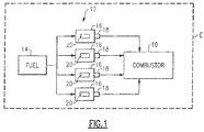
- FIG. 1 shows a schematic representation of a combustor 10 for a gas turbine engine E.
- a plurality of nozzle assemblies 12 is circumferentially spaced about an engine axis to deliver fuel from a fuel supply system 14 to the combustor 10.
- Each nozzle assembly 12 includes a housing 16 and a nozzle 18 that sprays fuel into the combustor 10.
- the subject invention provides a metering valve 20 in each housing 16 to independently control the fuel supply at each nozzle location.
- the metering valve 20 includes the nozzle housing 16 which has an outlet 22 configured to direct fuel into the combustor 10.
- a first housing sub-component 24 is seated in the housing 16 at the outlet 22 and a second housing sub-component 26 is seated within the first housing sub-component 24.
- a motor 28 is received within the housing 16.
- the motor 28 comprises a solenoid that includes a core 30 surrounded by a coil 32 and a cover 34 that encloses the core 30 and coil 32.
- the cover 34 is enclosed within the housing 16.
- a valve assembly 36 is actuated by the motor 28 to deliver fuel to the outlet 22 of the housing 16.
- the valve assembly 36 is shown in greater detail in the magnified view of Figure 3 .
- the valve assembly 36 includes a base plate 38 having a first portion 38a that extends into the second housing sub-component 26 ( Figure 2 ) and a second portion 38b that forms an outwardly extending flange.
- a center opening 40 is formed within the base plate 38 that is in fluid communication with the nozzle assembly 12 and defines a nozzle axis A.
- the nozzle assembly 12 includes a ball bearing, bellows, nozzle, and valve flow deflector as known.
- a solenoid side wall structure 42 surrounds the base plate 38 and nozzle assembly 12.
- the nozzle assembly12 is coupled to a plunger 44 that is configured to be magnetically attracted toward the core 30 and coil 32 when the solenoid is energized.
- One or more flexures 46 are used in the metering valve 20 to provide a spring force that resists the magnetic attraction of the plunger 44.
- a first set of shims 48 are installed within the assembly to properly locate the plunger 44 relative to the solenoid sidewall 42.
- a second set of shims 50 are installed within the assembly to set the flexure(s) 46 preload for ball and seat sealing 56, 58.
- a spacer 52 ( Figure 2 ) is installed axially between the coil 32 and the plunger 44 and serves as a max stop of the solenoid.
- a locking ring 54 is installed radially between the baseplate 38 and the retaining fingers to secure and retain the assembly 200.
- the center opening 40 of the base plate 38 provides a seat 56 for the valve assembly 36.
- the valve assembly 36 includes a ball 58 that moves out of engagement with the seat 56 when the plunger 44 is actuated to move upwardly as viewed in Figure 4 .
- the spring force of the flexure 46 returns the ball 58 to the seated position.
- the motor 28 has an outer peripheral surface 60 that is defined by a first radial dimension R1 relative to the nozzle center axis A.
- the flexure 46 includes an outermost peripheral surface 62 that surrounds the center axis A and which is defined by a second radial dimension R2 that is equal or less than the first radial dimension R1. This allows the metering valve 20 to be easily packaged within existing nozzle housing 16 without having to increase the size of the housing. This will be discussed in greater detail below.
- the flexure 46 is shown in greater detail in Figures 5-7 .
- the flexure 46 includes a unique retaining feature 64 formed in a flexure body 66.
- the retaining feature 64 is located radially between the center axis A and the outmost peripheral surface 62.
- the flexure body 66 includes a first body portion 68 that provides an opening 70 for the nozzle assembly 12 and a second body portion 72 spaced radially outwardly from the first body portion 68 by a gap 74 such that a significant amount of the area between the portions 68, 72 is open.
- the second body portion 72 defines the outermost peripheral surface 62.
- At least two arms 76 extend radially outwardly from the first body portion 68 to the second body portion 72.
- the arms 76 are spaced apart from each other by approximately ninety degrees.
- the first body portion 68 comprises a first ring and the second body portion 72 comprises a second ring that surrounds the first ring.
- the rings are concentric with the axis A and the arms 76 extend radially outwardly to connect the rings.
- the flexure body 66 includes a third body portion78 that extends radially inwardly from the second body portion 72 toward the first body portion 68. In one example, the third body portion 78 does not contact the first body portion 68.
- the third body portion 78 includes the retaining feature 64.
- the retaining feature 64 is circumferentially spaced apart from each of the arms 76. In one example, the retaining feature 64 is positioned approximately one hundred and eighty degrees from the center point C ( Figure 6 ) on the second body portion 72 of the space between the arms 76.
- the retaining feature 64 comprises a mount interface for a fastener 80.
- the third body portion 78 includes an anti-rotation feature to prevent the fastener 80 from rotating relative to the flexure body 66 once the flexure 46 is installed within the metering valve 20.
- the third body portion 78 includes an opening 82 configured to receive the fastener 80.
- the anti-rotation feature comprises a recessed area 84 formed within an upper surface 86 of the third body portion 78 and which surrounds the opening 82.
- the recessed area 84 is configured to receive an enlarged portion of the fastener 80.
- the recessed area 84 is defined by at least two side walls 88 which cooperate with the enlarged portion of the fastener 80 to prevent rotation. Thus, only a single fastener is required as a retention feature.
- the fastener 80 comprises a modified sex bolt with a first fastener portion 80a and a second fastener portion 80b ( Figure 3 ).
- the second fastener portion 80b of the sex bolt is configured to comprise a nut portion with a rectangular head 80c, which acts as an anti-rotation feature when located within the recessed area 84.
- the recessed area 84 is configured to have a polygonal shape that corresponds to the second fastener portion 80b. The recessed area 84 not only provides anti-rotation, but also provides clearance to prevent interaction with the plunger operation as the head 80c of the second fastener portion 80b does not extend outwardly of an uppermost surface of the flexure 46.
- the flexure 46 provides adjustability between the ball 58 and seat 56 to always provide a completely sealed configuration. This adjustability is controlled by a diametrical clearance between an outer diameter of the second fastener portion 80b and an inner diameter of the opening 82, plus the outer diameter of second fastener portion 80b and the inner diameter of the baseplate 38c
- the location of the retaining feature 64 within an envelope defined by the solenoid body provides a very compact configuration from a packaging perspective but does not interfere with the functions provided by the flexure 46.
- the flexure 46 provides the spring force to counter the magnetic attraction of the plunger 44.
- the flexure 46 also serves to center the plunger 44 to prevent grounding to the solenoid side walls 42.
- the centering function is provided by the arms 76 which hold the flexure rigid in a radial direction relative to the axis A.
- the flexure 46 provides adjustability for proper sealing between the ball 58 and seat 56. All of these functions are imperative to ensure proper performance of the metering valve 20.
- a flexure 100 comprised a triangular shaped body having a center portion 102 for the nozzle assembly 12, and two arms 104 extending from the center portion 102 to provide an attachment interface.
- a bridge 106 extended between the arms to form the triangle shape.
- Each arm 104 included a hole 108 to receive a fastener 110 ( Figure 10 ).
- the flexure retention at 110 is located radially outward of the plunger 44 and solenoid motor 28 to prevent interference with the plunger 44 and to provide the desired adjustability.
- this radial extension of the flexure retention is unacceptable from a packaging perspective as it requires a modified nozzle housing 112. As such, this existing configuration is too big and heavy to be utilized within the combustor described above.
- the subject invention provides a compact solution by minimizing the packaging to the smallest capability.
- a significant reduction in the radial package is provided without limitation of the required functionality as the flexure retaining feature 64 is now moved to within the radial confines of the solenoid body.
- the flexure 46 includes an anti-rotation feature and provides clearance to prevent interaction with plunger operation. Finally, sealing adjustability is also maintained is now controlled by the diametrical clearance between the fastener and the fastener hole.
- Figure 8A shows an assembled solenoid and valve assembly 200.
- Figure 8B shows a section view of the assembly 200 and shows the position of the flexure 46.
- the assembly 200 is inserted into the nozzle housing 16 in a direction along the center axis A, as shown in Figure 8C .
- a housing cover 202 is then installed to completely enclose the assembly 200 within the housing 16 as shown in Figures 8D-8E .
- no portion of the flexure 46 extends outwardly of an envelope defined by the assembly 200.
Landscapes
- Engineering & Computer Science (AREA)
- Chemical & Material Sciences (AREA)
- Combustion & Propulsion (AREA)
- General Engineering & Computer Science (AREA)
- Mechanical Engineering (AREA)
- Fuel-Injection Apparatus (AREA)
Abstract
Description
- The present invention generally relates to a metering valve assembly for a gas turbine engine that includes a flexure that provides a desired spring force, as well as providing adjustability and centering capabilities, and which is easily packaged within the tight design constraints that are required for more efficient engine configurations.
- Gas turbine engines include a compressor to pressurize an airflow, a combustor for burning fuel in the presence of the pressurized air, and a turbine that extracts energy from the resultant combustion gases. The combustor includes radially spaced inner and outer liners that define an annular combustion chamber therebetween. A plurality of circumferentially distributed fuel nozzles project symmetrically into a forward section of the combustion chamber through a respective fuel nozzle guide to supply the fuel to be mixed with the pressurized air.
- It is desirable to ignite the fuel quickly and smoothly under all operating conditions to maintain the desired level of fuel efficiency. In one example, a single metering valve is used to supply fuel to all of the fuel nozzles. With this configuration it is difficult to maintain a controlled and uniform burn under all operating configurations.
- A flexure for a metering valve has a flexure body defining a center axis to be aligned with a fuel nozzle. The flexure body includes an outermost peripheral surface surrounding the center axis. A retaining feature is formed in the flexure body and is configured to mount the flexure body to a metering valve component. The retaining feature is located radially between the center axis and the outmost peripheral surface. A metering valve is also disclosed.
- These and other features of the present invention can be best understood from the following specification and drawings, the following of which is a brief description.
-
-
Figure 1 shows a schematic representation of a combustor for a gas turbine engine. -
Figure 2 shows an exploded view of a nozzle and metering valve assembly as used in the combustor ofFigure 1 . -
Figure 3 shows a magnified view of a portion of the nozzle and metering valve assembly ofFigure 2 . -
Figure 4 is a partial, cross-sectional view of the nozzle and metering valve assembly ofFigure 2 . -
Figure 5 shows a top perspective view of a flexure as used in the nozzle and metering valve assembly ofFigure 2 . -
Figure 6 shows a top perspective view of a locking ring, base plate and flexure assembly of the nozzle and metering valve assembly ofFigure 2 . -
Figure 7 is a cross-sectional view of the assembled nozzle and metering valve assembly ofFigure 2 . -
Figure 8A shows a metering valve assembly prior to installation in a nozzle housing. -
Figure 8B shows a first step of installing the metering valve assembly into the nozzle housing. -
Figure 8C shows a subsequent step of installing the metering valve assembly into the nozzle housing. -
Figure 8D shows subsequent step of installing the metering valve assembly into the nozzle housing. -
Figure 8E shows the metering valve assembly as assembled into the nozzle housing. -
Figure 9 shows a prior art flexure -
Figure 10 shows the prior art flexure ofFigure 9 as installed in a nozzle housing. -
Figure 1 shows a schematic representation of acombustor 10 for a gas turbine engine E. As known, a plurality ofnozzle assemblies 12 is circumferentially spaced about an engine axis to deliver fuel from a fuel supply system 14 to thecombustor 10. Eachnozzle assembly 12 includes ahousing 16 and anozzle 18 that sprays fuel into thecombustor 10. The subject invention provides ametering valve 20 in eachhousing 16 to independently control the fuel supply at each nozzle location. - As shown in
Figure 2 , themetering valve 20 includes thenozzle housing 16 which has anoutlet 22 configured to direct fuel into thecombustor 10. Afirst housing sub-component 24 is seated in thehousing 16 at theoutlet 22 and asecond housing sub-component 26 is seated within thefirst housing sub-component 24. - A
motor 28 is received within thehousing 16. In one example, themotor 28 comprises a solenoid that includes acore 30 surrounded by acoil 32 and acover 34 that encloses thecore 30 andcoil 32. Thecover 34 is enclosed within thehousing 16. - A
valve assembly 36 is actuated by themotor 28 to deliver fuel to theoutlet 22 of thehousing 16. Thevalve assembly 36 is shown in greater detail in the magnified view ofFigure 3 . Thevalve assembly 36 includes abase plate 38 having afirst portion 38a that extends into the second housing sub-component 26 (Figure 2 ) and asecond portion 38b that forms an outwardly extending flange. Acenter opening 40 is formed within thebase plate 38 that is in fluid communication with thenozzle assembly 12 and defines a nozzle axis A. Thenozzle assembly 12 includes a ball bearing, bellows, nozzle, and valve flow deflector as known. A solenoidside wall structure 42 surrounds thebase plate 38 andnozzle assembly 12. The nozzle assembly12 is coupled to aplunger 44 that is configured to be magnetically attracted toward thecore 30 andcoil 32 when the solenoid is energized. - One or
more flexures 46 are used in themetering valve 20 to provide a spring force that resists the magnetic attraction of theplunger 44. A first set ofshims 48 are installed within the assembly to properly locate theplunger 44 relative to thesolenoid sidewall 42. A second set ofshims 50 are installed within the assembly to set the flexure(s) 46 preload for ball and seat sealing 56, 58. A spacer 52 (Figure 2 ) is installed axially between thecoil 32 and theplunger 44 and serves as a max stop of the solenoid. Alocking ring 54 is installed radially between thebaseplate 38 and the retaining fingers to secure and retain theassembly 200. - As shown in the section view of
Figure 4 , the center opening 40 of thebase plate 38 provides aseat 56 for thevalve assembly 36. Thevalve assembly 36 includes aball 58 that moves out of engagement with theseat 56 when theplunger 44 is actuated to move upwardly as viewed inFigure 4 . When not actuated by themotor 28, the spring force of theflexure 46 returns theball 58 to the seated position. - As shown in
Figure 4 , themotor 28 has an outerperipheral surface 60 that is defined by a first radial dimension R1 relative to the nozzle center axis A. Theflexure 46 includes an outermostperipheral surface 62 that surrounds the center axis A and which is defined by a second radial dimension R2 that is equal or less than the first radial dimension R1. This allows themetering valve 20 to be easily packaged within existingnozzle housing 16 without having to increase the size of the housing. This will be discussed in greater detail below. - The
flexure 46 is shown in greater detail inFigures 5-7 . Theflexure 46 includes aunique retaining feature 64 formed in aflexure body 66. Theretaining feature 64 is located radially between the center axis A and the outmostperipheral surface 62. Theflexure body 66 includes afirst body portion 68 that provides anopening 70 for thenozzle assembly 12 and asecond body portion 72 spaced radially outwardly from thefirst body portion 68 by agap 74 such that a significant amount of the area between theportions second body portion 72 defines the outermostperipheral surface 62. At least twoarms 76 extend radially outwardly from thefirst body portion 68 to thesecond body portion 72. - In one example, the
arms 76 are spaced apart from each other by approximately ninety degrees. - In one example, the
first body portion 68 comprises a first ring and thesecond body portion 72 comprises a second ring that surrounds the first ring. The rings are concentric with the axis A and thearms 76 extend radially outwardly to connect the rings. - The
flexure body 66 includes a third body portion78 that extends radially inwardly from thesecond body portion 72 toward thefirst body portion 68. In one example, thethird body portion 78 does not contact thefirst body portion 68. Thethird body portion 78 includes the retainingfeature 64. The retainingfeature 64 is circumferentially spaced apart from each of thearms 76. In one example, the retainingfeature 64 is positioned approximately one hundred and eighty degrees from the center point C (Figure 6 ) on thesecond body portion 72 of the space between thearms 76. - In one example, the retaining
feature 64 comprises a mount interface for afastener 80. Thethird body portion 78 includes an anti-rotation feature to prevent thefastener 80 from rotating relative to theflexure body 66 once theflexure 46 is installed within themetering valve 20. Thethird body portion 78 includes anopening 82 configured to receive thefastener 80. The anti-rotation feature comprises a recessedarea 84 formed within anupper surface 86 of thethird body portion 78 and which surrounds theopening 82. The recessedarea 84 is configured to receive an enlarged portion of thefastener 80. The recessedarea 84 is defined by at least twoside walls 88 which cooperate with the enlarged portion of thefastener 80 to prevent rotation. Thus, only a single fastener is required as a retention feature. - In one example, the
fastener 80 comprises a modified sex bolt with afirst fastener portion 80a and asecond fastener portion 80b (Figure 3 ). Thesecond fastener portion 80b of the sex bolt is configured to comprise a nut portion with a rectangular head 80c, which acts as an anti-rotation feature when located within the recessedarea 84. In one example, the recessedarea 84 is configured to have a polygonal shape that corresponds to thesecond fastener portion 80b. The recessedarea 84 not only provides anti-rotation, but also provides clearance to prevent interaction with the plunger operation as the head 80c of thesecond fastener portion 80b does not extend outwardly of an uppermost surface of theflexure 46. Also, theflexure 46 provides adjustability between theball 58 andseat 56 to always provide a completely sealed configuration. This adjustability is controlled by a diametrical clearance between an outer diameter of thesecond fastener portion 80b and an inner diameter of theopening 82, plus the outer diameter ofsecond fastener portion 80b and the inner diameter of thebaseplate 38c - The location of the retaining
feature 64 within an envelope defined by the solenoid body provides a very compact configuration from a packaging perspective but does not interfere with the functions provided by theflexure 46. As discussed above, theflexure 46 provides the spring force to counter the magnetic attraction of theplunger 44. Theflexure 46 also serves to center theplunger 44 to prevent grounding to thesolenoid side walls 42. The centering function is provided by thearms 76 which hold the flexure rigid in a radial direction relative to the axis A. Further, theflexure 46 provides adjustability for proper sealing between theball 58 andseat 56. All of these functions are imperative to ensure proper performance of themetering valve 20. - In a prior known configuration shown in
Figures 9-10 , aflexure 100 comprised a triangular shaped body having acenter portion 102 for thenozzle assembly 12, and twoarms 104 extending from thecenter portion 102 to provide an attachment interface. Abridge 106 extended between the arms to form the triangle shape. Eacharm 104 included ahole 108 to receive a fastener 110 (Figure 10 ). - In this known configuration, the flexure retention at 110 is located radially outward of the
plunger 44 andsolenoid motor 28 to prevent interference with theplunger 44 and to provide the desired adjustability. However, this radial extension of the flexure retention is unacceptable from a packaging perspective as it requires a modifiednozzle housing 112. As such, this existing configuration is too big and heavy to be utilized within the combustor described above. - The subject invention provides a compact solution by minimizing the packaging to the smallest capability. A significant reduction in the radial package is provided without limitation of the required functionality as the
flexure retaining feature 64 is now moved to within the radial confines of the solenoid body. Further, theflexure 46 includes an anti-rotation feature and provides clearance to prevent interaction with plunger operation. Finally, sealing adjustability is also maintained is now controlled by the diametrical clearance between the fastener and the fastener hole. - Installation of the
subject metering valve 20 in an existingnozzle housing 16 is shown inFigures 8A-8E. Figure 8A shows an assembled solenoid andvalve assembly 200.Figure 8B shows a section view of theassembly 200 and shows the position of theflexure 46. Theassembly 200 is inserted into thenozzle housing 16 in a direction along the center axis A, as shown inFigure 8C . Ahousing cover 202 is then installed to completely enclose theassembly 200 within thehousing 16 as shown inFigures 8D-8E . As shown, no portion of theflexure 46 extends outwardly of an envelope defined by theassembly 200. - The incorporation of this invention into the metering valve provides a compact and light weight solution such that each nozzle will have independent fuel metering. This can greatly advance the engine combustion technology and performance. Independent fuel modulation at the combustor has monumental effects on combustion technology. Some primary advantages include fuel efficiency, thermal management of combustor hardware, and engine acoustic control.
- The preceding description is exemplary rather than limiting in nature. Variations and modifications to the disclosed examples may become apparent to those skilled in the art that do not necessarily depart from the essence of this disclosure. The scope of legal protection given to this disclosure can only be determined by studying the following claims.
- Although a combination of features is shown in the illustrated examples, not all of them need to be combined to realize the benefits of various embodiments of this disclosure. In other words, a system designed according to an embodiment of this disclosure will not necessarily include all of the features shown in any one of the Figures or all of the portions schematically shown in the Figures. Moreover, selected features of one example embodiment may be combined with selected features of other example embodiments.
Claims (15)
- A flexure (46) for a metering valve (20) comprising:a flexure body (66) defining a center axis to be aligned with a fuel nozzle, the flexure body (66) including an outermost peripheral surface surrounding the center axis; anda retaining feature (64) formed in the flexure body (66) and configured to mount the flexure body (66) to a metering valve component, the retaining feature (64) being located radially between the center axis and the outmost peripheral surface.
- The flexure (46) according to claim 1 wherein the flexure body includes a first body portion (68) providing an opening (70) for the fuel nozzle and a second body portion (72) spaced radially outwardly from the first body portion by a gap, the second body portion defining the outermost peripheral surface, and further including at least two arms (76) extending radially outwardly from the first body portion to the second body portion (72).
- The flexure according to claim 2 wherein the arms (76) are spaced apart from each other by approximately ninety degrees.
- The flexure according to claims 2 or 3 wherein the first body portion (68) comprises a first ring and the second body portion (72) comprises a second ring that surrounds the first ring.
- The flexure according to claims 2-4 wherein the flexure body (66) includes a third body portion (78) extending radially inwardly from the second body portion (72) toward the first body portion (68), the third body portion (78) including the retaining feature (64).
- The flexure according to claim 5 wherein the retaining feature (64) is circumferentially spaced apart from each of the at least two arms (76).
- The flexure according to claim 6 wherein the retaining feature (64) comprises a mount interface for a fastener (84).
- The flexure according to claim 7 wherein the third body portion (78) includes an anti-rotation feature to prevent the fastener (80) from rotating relative to the flexure body once the flexure is installed within the metering valve (20).
- The flexure according to claim 8 wherein the third body portion (78) includes an opening (82) configured to receive the fastener (80), and wherein the anti-rotation feature comprises a recessed area (84) formed within an upper surface of the third body portion (78) and which surrounds the opening (82), the recessed area (84) configured to receive a nut for the fastener (80).
- The flexure according to claim 9 wherein the recessed area (84) is defined by at least two side walls.
- A metering valve (20) for a combustor in a gas turbine engine comprising:a nozzle housing (16) having an outlet configured to direct fuel into the combustor;an actuator (28) received within the nozzle housing (16), the actuator defining an outer peripheral surface;a valve assembly (36) to be actuated by the actuator;a fuel nozzle (18) configured to receive fuel from the valve assembly (36);at least one flexure (46) associated with the valve assembly, the flexure defining a center axis to be aligned with the fuel nozzle; andwherein the outer peripheral surface of the actuator is defined by a first radial dimension, and wherein the flexure includes an outermost peripheral surface that surrounds the center axis and which is defined by a second radial dimension that is equal or less than the first radial dimension.
- The metering valve according to claim 11 wherein the flexure (46) includes a retaining feature (64) configured to mount the flexure (46) to the valve assembly (36), the retaining feature (64) being located radially between the center axis and the outmost peripheral surface.
- The metering valve according to claim 12 wherein the flexure (46) includes a first body portion (68) providing an opening for the fuel nozzle (70), a second body portion (72) spaced radially outwardly from the first body portion (68) by a gap, the second body portion (72) defining the outermost peripheral surface, and a third body portion (78) extending radially inwardly from the second body portion (72) toward the first body portion (68), the third body portion (78) including the retaining feature (64).
- The metering valve according to claim 13 further including at least two arms (76) extending radially outwardly from the first body portion (68) to the second body portion (72), and wherein the retaining feature (64) is circumferentially spaced apart from each of the at least two arms (76).
- The metering valve according to claim 13 wherein the third body portion (78) includes an opening (82) that receives a fastener (80), and including a recessed area (84) formed within an upper surface of the third body portion (78) and which surrounds the opening (82), the recessed area (84) configured to receive a nut for the fastener (80), and wherein the recessed area (84) comprises an anti-rotation feature.
Applications Claiming Priority (1)
| Application Number | Priority Date | Filing Date | Title |
|---|---|---|---|
| US14/596,272 US10082088B2 (en) | 2015-01-14 | 2015-01-14 | Flexure for metering valve assembly with retaining feature |
Publications (2)
| Publication Number | Publication Date |
|---|---|
| EP3045700A1 true EP3045700A1 (en) | 2016-07-20 |
| EP3045700B1 EP3045700B1 (en) | 2020-02-26 |
Family
ID=55085590
Family Applications (1)
| Application Number | Title | Priority Date | Filing Date |
|---|---|---|---|
| EP16150750.4A Active EP3045700B1 (en) | 2015-01-14 | 2016-01-11 | Flexure for metering valve assembly |
Country Status (2)
| Country | Link |
|---|---|
| US (1) | US10082088B2 (en) |
| EP (1) | EP3045700B1 (en) |
Families Citing this family (2)
| Publication number | Priority date | Publication date | Assignee | Title |
|---|---|---|---|---|
| US20180163635A1 (en) * | 2016-12-13 | 2018-06-14 | Delavan Inc | Fluid valves |
| US11105437B2 (en) | 2017-07-03 | 2021-08-31 | Continental Automotive Systems, Inc. | Combined inlet and outlet check valve seat |
Citations (3)
| Publication number | Priority date | Publication date | Assignee | Title |
|---|---|---|---|---|
| EP0578578A1 (en) * | 1992-07-10 | 1994-01-12 | Selas Corporation Of America | Apparatus and method for mixing gases |
| US20030168619A1 (en) * | 2002-02-28 | 2003-09-11 | Jansen Harvey B. | Active combustion fuel valve |
| US20140367596A1 (en) * | 2009-10-15 | 2014-12-18 | Pivotal Systems Corporation | Method and apparatus for gas flow control |
Family Cites Families (26)
| Publication number | Priority date | Publication date | Assignee | Title |
|---|---|---|---|---|
| US3250293A (en) * | 1963-10-17 | 1966-05-10 | American Brake Shoe Co | Electric and fluid pressure operated valve mechanism |
| US3902315A (en) * | 1974-06-12 | 1975-09-02 | United Aircraft Corp | Starting fuel control system for gas turbine engines |
| US3926405A (en) * | 1974-08-21 | 1975-12-16 | Valcor Eng Corp | Solenoid operated proportional valve |
| US3995660A (en) | 1975-12-08 | 1976-12-07 | General Electric Company | Flow metering and dividing valve |
| US4120230A (en) * | 1977-02-23 | 1978-10-17 | Pilgrim Engineering Developments Limited | Self-straining bolts |
| US4226365A (en) | 1979-06-27 | 1980-10-07 | United Technologies Corporation | Fuel distribution valve for a gas turbine engine |
| US4407324A (en) * | 1981-02-17 | 1983-10-04 | Caddell John P | Valve stem cover apparatus |
| US4463332A (en) * | 1983-02-23 | 1984-07-31 | South Bend Controls, Inc. | Adjustable, rectilinear motion proportional solenoid |
| GB8517744D0 (en) | 1985-07-12 | 1995-11-08 | Rolls Royce | Fuel control system |
| US4637420A (en) * | 1985-12-16 | 1987-01-20 | United Technologies Corporation | Metering valve |
| US4751942A (en) | 1987-04-24 | 1988-06-21 | United Technologies Corporation | Multi-function fuel metering valve |
| US4838313A (en) * | 1987-05-28 | 1989-06-13 | Aisin Aw Co., Ltd. | Solenoid-operated pressure control valve |
| US5407174A (en) * | 1990-08-31 | 1995-04-18 | Puritan-Bennett Corporation | Proportional electropneumatic solenoid-controlled valve |
| US5275042A (en) * | 1990-10-04 | 1994-01-04 | Isco, Inc. | Variable gate flow analyzing method and apparatus |
| US5116362A (en) | 1990-12-03 | 1992-05-26 | United Technologies Corporation | Fuel metering and actuation system |
| US5339636A (en) | 1992-12-04 | 1994-08-23 | United Technologies Corporation | Fuel splitter valve assembly for gas turbine |
| US5896737A (en) | 1997-06-16 | 1999-04-27 | United Technologies Corporation | Combined pressure regulating and fuel flow system |
| US6401749B1 (en) * | 1998-07-09 | 2002-06-11 | Parker Hannifin Corporation | Asymmetrically loaded check valve |
| JP2000193007A (en) * | 1998-12-22 | 2000-07-14 | Fukoku Co Ltd | Leaf spring integrated core and method of manufacturing the same |
| US6390129B2 (en) * | 1999-12-15 | 2002-05-21 | Jansen's Aircraft Systems Controls, Inc. | Proportional solenoid-operated fluid metering device |
| US6443183B1 (en) * | 2000-06-07 | 2002-09-03 | Transcend Inc. | Valve and assembly for axially movable members |
| US7984728B2 (en) * | 2004-10-22 | 2011-07-26 | Continental Automotive Systems Us, Inc. | Fuel pressure regulator valve assembly |
| GB0526330D0 (en) | 2005-12-23 | 2006-02-01 | Rolls Royce Plc | Engine health monitoring |
| US8176897B1 (en) * | 2006-06-29 | 2012-05-15 | E-Controls, Inc. | Electronic pressure regulator |
| GB0913097D0 (en) | 2009-07-28 | 2009-09-02 | Rolls Royce Goodrich Engine Co | Fuel system |
| DE102012104285A1 (en) * | 2012-05-16 | 2013-11-21 | Svm Schultz Verwaltungs-Gmbh & Co. Kg | Valve |
-
2015
- 2015-01-14 US US14/596,272 patent/US10082088B2/en active Active
-
2016
- 2016-01-11 EP EP16150750.4A patent/EP3045700B1/en active Active
Patent Citations (3)
| Publication number | Priority date | Publication date | Assignee | Title |
|---|---|---|---|---|
| EP0578578A1 (en) * | 1992-07-10 | 1994-01-12 | Selas Corporation Of America | Apparatus and method for mixing gases |
| US20030168619A1 (en) * | 2002-02-28 | 2003-09-11 | Jansen Harvey B. | Active combustion fuel valve |
| US20140367596A1 (en) * | 2009-10-15 | 2014-12-18 | Pivotal Systems Corporation | Method and apparatus for gas flow control |
Also Published As
| Publication number | Publication date |
|---|---|
| US20160201576A1 (en) | 2016-07-14 |
| EP3045700B1 (en) | 2020-02-26 |
| US10082088B2 (en) | 2018-09-25 |
Similar Documents
| Publication | Publication Date | Title |
|---|---|---|
| US5867976A (en) | Self-retained borescope plug | |
| US10247101B2 (en) | Device for mounting a spark plug in a combustion engine of a gas turbine engine | |
| US10041413B2 (en) | Igniter assembly for a gas turbine engine | |
| JP4081090B2 (en) | Turbofan jet engine with accessory distribution support | |
| EP1740798B1 (en) | Improved variable geometry assembly for turbochargers | |
| US6864771B2 (en) | Electromagnetic actuator | |
| EP1507118A2 (en) | Combustor dome assembly of a gas turbine engine having a free floating swirler | |
| US10480662B2 (en) | Steam valve and steam turbine system | |
| JP2009525424A (en) | Turbocharger | |
| EP2518407A2 (en) | A head part of an annular combustion chamber | |
| US20130291544A1 (en) | Gas turbine engine combustor surge retention | |
| JP2578533B2 (en) | Turbomachinery fuel injection assembly | |
| EP3045700B1 (en) | Flexure for metering valve assembly | |
| JP2010540814A (en) | Fluid injector with reed valve | |
| CA2858041C (en) | Combustor floating collar assembly | |
| US11162465B2 (en) | Fuel injection valve | |
| US20140027545A1 (en) | Fuel injection valve | |
| US9897319B2 (en) | Igniter position for a combustor of a gas turbine engine | |
| EP2971967B1 (en) | Inverted cap igniter tube | |
| CN104204460B (en) | Air Blocking Ring Assembly with Radial Retention | |
| US20090255250A1 (en) | Switch valve for exhaust gas turbocharger system | |
| US11802512B2 (en) | Spark plug for a single-piece combustion chamber | |
| CN105715312A (en) | Sealing-Coupled Apparatus Of Turbocharger | |
| JP4021405B2 (en) | Fuel injection valve | |
| US9896058B2 (en) | Gas generator |
Legal Events
| Date | Code | Title | Description |
|---|---|---|---|
| PUAI | Public reference made under article 153(3) epc to a published international application that has entered the european phase |
Free format text: ORIGINAL CODE: 0009012 |
|
| AK | Designated contracting states |
Kind code of ref document: A1 Designated state(s): AL AT BE BG CH CY CZ DE DK EE ES FI FR GB GR HR HU IE IS IT LI LT LU LV MC MK MT NL NO PL PT RO RS SE SI SK SM TR |
|
| AX | Request for extension of the european patent |
Extension state: BA ME |
|
| STAA | Information on the status of an ep patent application or granted ep patent |
Free format text: STATUS: REQUEST FOR EXAMINATION WAS MADE |
|
| 17P | Request for examination filed |
Effective date: 20170118 |
|
| RBV | Designated contracting states (corrected) |
Designated state(s): AL AT BE BG CH CY CZ DE DK EE ES FI FR GB GR HR HU IE IS IT LI LT LU LV MC MK MT NL NO PL PT RO RS SE SI SK SM TR |
|
| STAA | Information on the status of an ep patent application or granted ep patent |
Free format text: STATUS: EXAMINATION IS IN PROGRESS |
|
| 17Q | First examination report despatched |
Effective date: 20171006 |
|
| GRAP | Despatch of communication of intention to grant a patent |
Free format text: ORIGINAL CODE: EPIDOSNIGR1 |
|
| STAA | Information on the status of an ep patent application or granted ep patent |
Free format text: STATUS: GRANT OF PATENT IS INTENDED |
|
| INTG | Intention to grant announced |
Effective date: 20190904 |
|
| GRAS | Grant fee paid |
Free format text: ORIGINAL CODE: EPIDOSNIGR3 |
|
| GRAA | (expected) grant |
Free format text: ORIGINAL CODE: 0009210 |
|
| STAA | Information on the status of an ep patent application or granted ep patent |
Free format text: STATUS: THE PATENT HAS BEEN GRANTED |
|
| AK | Designated contracting states |
Kind code of ref document: B1 Designated state(s): AL AT BE BG CH CY CZ DE DK EE ES FI FR GB GR HR HU IE IS IT LI LT LU LV MC MK MT NL NO PL PT RO RS SE SI SK SM TR |
|
| REG | Reference to a national code |
Ref country code: GB Ref legal event code: FG4D |
|
| REG | Reference to a national code |
Ref country code: CH Ref legal event code: EP |
|
| REG | Reference to a national code |
Ref country code: DE Ref legal event code: R096 Ref document number: 602016030382 Country of ref document: DE |
|
| REG | Reference to a national code |
Ref country code: AT Ref legal event code: REF Ref document number: 1237902 Country of ref document: AT Kind code of ref document: T Effective date: 20200315 |
|
| REG | Reference to a national code |
Ref country code: IE Ref legal event code: FG4D |
|
| PG25 | Lapsed in a contracting state [announced via postgrant information from national office to epo] |
Ref country code: NO Free format text: LAPSE BECAUSE OF FAILURE TO SUBMIT A TRANSLATION OF THE DESCRIPTION OR TO PAY THE FEE WITHIN THE PRESCRIBED TIME-LIMIT Effective date: 20200526 Ref country code: RS Free format text: LAPSE BECAUSE OF FAILURE TO SUBMIT A TRANSLATION OF THE DESCRIPTION OR TO PAY THE FEE WITHIN THE PRESCRIBED TIME-LIMIT Effective date: 20200226 Ref country code: FI Free format text: LAPSE BECAUSE OF FAILURE TO SUBMIT A TRANSLATION OF THE DESCRIPTION OR TO PAY THE FEE WITHIN THE PRESCRIBED TIME-LIMIT Effective date: 20200226 |
|
| REG | Reference to a national code |
Ref country code: NL Ref legal event code: MP Effective date: 20200226 |
|
| REG | Reference to a national code |
Ref country code: LT Ref legal event code: MG4D |
|
| PG25 | Lapsed in a contracting state [announced via postgrant information from national office to epo] |
Ref country code: HR Free format text: LAPSE BECAUSE OF FAILURE TO SUBMIT A TRANSLATION OF THE DESCRIPTION OR TO PAY THE FEE WITHIN THE PRESCRIBED TIME-LIMIT Effective date: 20200226 Ref country code: GR Free format text: LAPSE BECAUSE OF FAILURE TO SUBMIT A TRANSLATION OF THE DESCRIPTION OR TO PAY THE FEE WITHIN THE PRESCRIBED TIME-LIMIT Effective date: 20200527 Ref country code: IS Free format text: LAPSE BECAUSE OF FAILURE TO SUBMIT A TRANSLATION OF THE DESCRIPTION OR TO PAY THE FEE WITHIN THE PRESCRIBED TIME-LIMIT Effective date: 20200626 Ref country code: BG Free format text: LAPSE BECAUSE OF FAILURE TO SUBMIT A TRANSLATION OF THE DESCRIPTION OR TO PAY THE FEE WITHIN THE PRESCRIBED TIME-LIMIT Effective date: 20200526 Ref country code: LV Free format text: LAPSE BECAUSE OF FAILURE TO SUBMIT A TRANSLATION OF THE DESCRIPTION OR TO PAY THE FEE WITHIN THE PRESCRIBED TIME-LIMIT Effective date: 20200226 Ref country code: SE Free format text: LAPSE BECAUSE OF FAILURE TO SUBMIT A TRANSLATION OF THE DESCRIPTION OR TO PAY THE FEE WITHIN THE PRESCRIBED TIME-LIMIT Effective date: 20200226 |
|
| PG25 | Lapsed in a contracting state [announced via postgrant information from national office to epo] |
Ref country code: NL Free format text: LAPSE BECAUSE OF FAILURE TO SUBMIT A TRANSLATION OF THE DESCRIPTION OR TO PAY THE FEE WITHIN THE PRESCRIBED TIME-LIMIT Effective date: 20200226 |
|
| PG25 | Lapsed in a contracting state [announced via postgrant information from national office to epo] |
Ref country code: RO Free format text: LAPSE BECAUSE OF FAILURE TO SUBMIT A TRANSLATION OF THE DESCRIPTION OR TO PAY THE FEE WITHIN THE PRESCRIBED TIME-LIMIT Effective date: 20200226 Ref country code: CZ Free format text: LAPSE BECAUSE OF FAILURE TO SUBMIT A TRANSLATION OF THE DESCRIPTION OR TO PAY THE FEE WITHIN THE PRESCRIBED TIME-LIMIT Effective date: 20200226 Ref country code: EE Free format text: LAPSE BECAUSE OF FAILURE TO SUBMIT A TRANSLATION OF THE DESCRIPTION OR TO PAY THE FEE WITHIN THE PRESCRIBED TIME-LIMIT Effective date: 20200226 Ref country code: DK Free format text: LAPSE BECAUSE OF FAILURE TO SUBMIT A TRANSLATION OF THE DESCRIPTION OR TO PAY THE FEE WITHIN THE PRESCRIBED TIME-LIMIT Effective date: 20200226 Ref country code: PT Free format text: LAPSE BECAUSE OF FAILURE TO SUBMIT A TRANSLATION OF THE DESCRIPTION OR TO PAY THE FEE WITHIN THE PRESCRIBED TIME-LIMIT Effective date: 20200719 Ref country code: ES Free format text: LAPSE BECAUSE OF FAILURE TO SUBMIT A TRANSLATION OF THE DESCRIPTION OR TO PAY THE FEE WITHIN THE PRESCRIBED TIME-LIMIT Effective date: 20200226 Ref country code: SK Free format text: LAPSE BECAUSE OF FAILURE TO SUBMIT A TRANSLATION OF THE DESCRIPTION OR TO PAY THE FEE WITHIN THE PRESCRIBED TIME-LIMIT Effective date: 20200226 Ref country code: LT Free format text: LAPSE BECAUSE OF FAILURE TO SUBMIT A TRANSLATION OF THE DESCRIPTION OR TO PAY THE FEE WITHIN THE PRESCRIBED TIME-LIMIT Effective date: 20200226 Ref country code: SM Free format text: LAPSE BECAUSE OF FAILURE TO SUBMIT A TRANSLATION OF THE DESCRIPTION OR TO PAY THE FEE WITHIN THE PRESCRIBED TIME-LIMIT Effective date: 20200226 |
|
| REG | Reference to a national code |
Ref country code: AT Ref legal event code: MK05 Ref document number: 1237902 Country of ref document: AT Kind code of ref document: T Effective date: 20200226 |
|
| REG | Reference to a national code |
Ref country code: DE Ref legal event code: R097 Ref document number: 602016030382 Country of ref document: DE |
|
| PLBE | No opposition filed within time limit |
Free format text: ORIGINAL CODE: 0009261 |
|
| STAA | Information on the status of an ep patent application or granted ep patent |
Free format text: STATUS: NO OPPOSITION FILED WITHIN TIME LIMIT |
|
| PG25 | Lapsed in a contracting state [announced via postgrant information from national office to epo] |
Ref country code: AT Free format text: LAPSE BECAUSE OF FAILURE TO SUBMIT A TRANSLATION OF THE DESCRIPTION OR TO PAY THE FEE WITHIN THE PRESCRIBED TIME-LIMIT Effective date: 20200226 Ref country code: IT Free format text: LAPSE BECAUSE OF FAILURE TO SUBMIT A TRANSLATION OF THE DESCRIPTION OR TO PAY THE FEE WITHIN THE PRESCRIBED TIME-LIMIT Effective date: 20200226 |
|
| 26N | No opposition filed |
Effective date: 20201127 |
|
| PG25 | Lapsed in a contracting state [announced via postgrant information from national office to epo] |
Ref country code: PL Free format text: LAPSE BECAUSE OF FAILURE TO SUBMIT A TRANSLATION OF THE DESCRIPTION OR TO PAY THE FEE WITHIN THE PRESCRIBED TIME-LIMIT Effective date: 20200226 Ref country code: SI Free format text: LAPSE BECAUSE OF FAILURE TO SUBMIT A TRANSLATION OF THE DESCRIPTION OR TO PAY THE FEE WITHIN THE PRESCRIBED TIME-LIMIT Effective date: 20200226 |
|
| REG | Reference to a national code |
Ref country code: DE Ref legal event code: R119 Ref document number: 602016030382 Country of ref document: DE |
|
| PG25 | Lapsed in a contracting state [announced via postgrant information from national office to epo] |
Ref country code: MC Free format text: LAPSE BECAUSE OF FAILURE TO SUBMIT A TRANSLATION OF THE DESCRIPTION OR TO PAY THE FEE WITHIN THE PRESCRIBED TIME-LIMIT Effective date: 20200226 |
|
| REG | Reference to a national code |
Ref country code: CH Ref legal event code: PL |
|
| PG25 | Lapsed in a contracting state [announced via postgrant information from national office to epo] |
Ref country code: LU Free format text: LAPSE BECAUSE OF NON-PAYMENT OF DUE FEES Effective date: 20210111 |
|
| REG | Reference to a national code |
Ref country code: BE Ref legal event code: MM Effective date: 20210131 |
|
| PG25 | Lapsed in a contracting state [announced via postgrant information from national office to epo] |
Ref country code: DE Free format text: LAPSE BECAUSE OF NON-PAYMENT OF DUE FEES Effective date: 20210803 Ref country code: CH Free format text: LAPSE BECAUSE OF NON-PAYMENT OF DUE FEES Effective date: 20210131 Ref country code: LI Free format text: LAPSE BECAUSE OF NON-PAYMENT OF DUE FEES Effective date: 20210131 |
|
| PG25 | Lapsed in a contracting state [announced via postgrant information from national office to epo] |
Ref country code: IE Free format text: LAPSE BECAUSE OF NON-PAYMENT OF DUE FEES Effective date: 20210111 |
|
| PG25 | Lapsed in a contracting state [announced via postgrant information from national office to epo] |
Ref country code: BE Free format text: LAPSE BECAUSE OF NON-PAYMENT OF DUE FEES Effective date: 20210131 |
|
| PG25 | Lapsed in a contracting state [announced via postgrant information from national office to epo] |
Ref country code: HU Free format text: LAPSE BECAUSE OF FAILURE TO SUBMIT A TRANSLATION OF THE DESCRIPTION OR TO PAY THE FEE WITHIN THE PRESCRIBED TIME-LIMIT; INVALID AB INITIO Effective date: 20160111 |
|
| P01 | Opt-out of the competence of the unified patent court (upc) registered |
Effective date: 20230522 |
|
| PG25 | Lapsed in a contracting state [announced via postgrant information from national office to epo] |
Ref country code: CY Free format text: LAPSE BECAUSE OF FAILURE TO SUBMIT A TRANSLATION OF THE DESCRIPTION OR TO PAY THE FEE WITHIN THE PRESCRIBED TIME-LIMIT Effective date: 20200226 |
|
| PG25 | Lapsed in a contracting state [announced via postgrant information from national office to epo] |
Ref country code: MK Free format text: LAPSE BECAUSE OF FAILURE TO SUBMIT A TRANSLATION OF THE DESCRIPTION OR TO PAY THE FEE WITHIN THE PRESCRIBED TIME-LIMIT Effective date: 20200226 |
|
| PG25 | Lapsed in a contracting state [announced via postgrant information from national office to epo] |
Ref country code: TR Free format text: LAPSE BECAUSE OF FAILURE TO SUBMIT A TRANSLATION OF THE DESCRIPTION OR TO PAY THE FEE WITHIN THE PRESCRIBED TIME-LIMIT Effective date: 20200226 |
|
| PG25 | Lapsed in a contracting state [announced via postgrant information from national office to epo] |
Ref country code: MT Free format text: LAPSE BECAUSE OF FAILURE TO SUBMIT A TRANSLATION OF THE DESCRIPTION OR TO PAY THE FEE WITHIN THE PRESCRIBED TIME-LIMIT Effective date: 20200226 |
|
| PGFP | Annual fee paid to national office [announced via postgrant information from national office to epo] |
Ref country code: GB Payment date: 20251219 Year of fee payment: 11 |
|
| PGFP | Annual fee paid to national office [announced via postgrant information from national office to epo] |
Ref country code: FR Payment date: 20251217 Year of fee payment: 11 |