EP3045630A1 - Führungsvorrichtung für die Führung eines Türblatts einer Schiebetür - Google Patents
Führungsvorrichtung für die Führung eines Türblatts einer Schiebetür Download PDFInfo
- Publication number
- EP3045630A1 EP3045630A1 EP15151190.4A EP15151190A EP3045630A1 EP 3045630 A1 EP3045630 A1 EP 3045630A1 EP 15151190 A EP15151190 A EP 15151190A EP 3045630 A1 EP3045630 A1 EP 3045630A1
- Authority
- EP
- European Patent Office
- Prior art keywords
- guide
- door leaf
- door
- section
- movement
- Prior art date
- Legal status (The legal status is an assumption and is not a legal conclusion. Google has not performed a legal analysis and makes no representation as to the accuracy of the status listed.)
- Granted
Links
Images



Classifications
-
- E—FIXED CONSTRUCTIONS
- E05—LOCKS; KEYS; WINDOW OR DOOR FITTINGS; SAFES
- E05D—HINGES OR SUSPENSION DEVICES FOR DOORS, WINDOWS OR WINGS
- E05D15/00—Suspension arrangements for wings
- E05D15/06—Suspension arrangements for wings for wings sliding horizontally more or less in their own plane
- E05D15/08—Suspension arrangements for wings for wings sliding horizontally more or less in their own plane consisting of two or more independent parts movable each in its own guides
-
- E—FIXED CONSTRUCTIONS
- E05—LOCKS; KEYS; WINDOW OR DOOR FITTINGS; SAFES
- E05D—HINGES OR SUSPENSION DEVICES FOR DOORS, WINDOWS OR WINGS
- E05D15/00—Suspension arrangements for wings
- E05D15/06—Suspension arrangements for wings for wings sliding horizontally more or less in their own plane
- E05D15/0621—Details, e.g. suspension or supporting guides
- E05D15/0626—Details, e.g. suspension or supporting guides for wings suspended at the top
- E05D15/0656—Bottom guides
-
- E—FIXED CONSTRUCTIONS
- E05—LOCKS; KEYS; WINDOW OR DOOR FITTINGS; SAFES
- E05Y—INDEXING SCHEME ASSOCIATED WITH SUBCLASSES E05D AND E05F, RELATING TO CONSTRUCTION ELEMENTS, ELECTRIC CONTROL, POWER SUPPLY, POWER SIGNAL OR TRANSMISSION, USER INTERFACES, MOUNTING OR COUPLING, DETAILS, ACCESSORIES, AUXILIARY OPERATIONS NOT OTHERWISE PROVIDED FOR, APPLICATION THEREOF
- E05Y2600/00—Mounting or coupling arrangements for elements provided for in this subclass
- E05Y2600/40—Mounting location; Visibility of the elements
- E05Y2600/46—Mounting location; Visibility of the elements in or on the wing
-
- E—FIXED CONSTRUCTIONS
- E05—LOCKS; KEYS; WINDOW OR DOOR FITTINGS; SAFES
- E05Y—INDEXING SCHEME ASSOCIATED WITH SUBCLASSES E05D AND E05F, RELATING TO CONSTRUCTION ELEMENTS, ELECTRIC CONTROL, POWER SUPPLY, POWER SIGNAL OR TRANSMISSION, USER INTERFACES, MOUNTING OR COUPLING, DETAILS, ACCESSORIES, AUXILIARY OPERATIONS NOT OTHERWISE PROVIDED FOR, APPLICATION THEREOF
- E05Y2800/00—Details, accessories and auxiliary operations not otherwise provided for
- E05Y2800/10—Additional functions
- E05Y2800/122—Telescopic action
Definitions
- the present invention relates to a guide device for guiding a door leaf of a sliding door and a sliding door system.
- sliding doors are used to open and close door openings in various ways.
- telescope solutions are often used.
- This means that such a sliding door has at least two door leaves, which can move in a telescoping manner to each other. In the open position, the two door leaves overlap in particular completely, while in the closed position, this overlap is reduced to a minimum.
- the two door leaves can also be referred to as high-speed and slow-speed.
- the door leaves are usually fastened in roller carriages, which are displaceably mounted in a roller track.
- This roller track is mounted above the door opening.
- a guide device is mounted on the floor, which prevents or limits this pendulum movement with corresponding guide surfaces.
- a disadvantage of the known solutions is precisely this fixed fixed guide device. So this is fixed to the ground, which accordingly an influence of the soil or a preparation of the soil is necessary. This also leads to the risk of a trip hazard arises when the floor guide is out of engagement with a door leaf. Not least, the mounting positions are limited in terms of location choice for such a guide device.
- a guide device serves to guide a door leaf of a sliding door.
- the guide device has a mounting portion for attachment to a movable first door leaf of the sliding door.
- a guide section with at least one guide surface for the guidance of a relative to the first door leaf movable second door leaf of the sliding door provided.
- the guide device is designed as a movable or moving guide device.
- the attachment portion is provided.
- the first door leaf is in particular the slow runner of a telescopic version of a sliding door. This means that moves during the movement of this first door leaf between an open position and a closed position to the same extent the attachment portion and thus the entire guide device.
- the moving distance of the sliding door is accordingly identical with the moving distance of the guiding device.
- a guide portion is provided in addition to the attachment portion.
- This has a guide surface for the guidance of the second door leaf.
- the second door leaf is preferably provided as a high-speed runner designed as a telescopic sliding door system. This means that a relative movement takes place between the first door leaf and the second door leaf. When the sliding door moves from the closed position to the open position, the second door leaf moves at a higher speed relative to the slower moving first door leaf. Due to the fact that the guide device also moves together with the first door leaf, the identical relative movement also takes place between the guide device and the second door leaf. This leads accordingly to a Relative movement between the at least one guide surface and the second door leaf.
- a guide surface for guidance is preferably formed as a flat surface. It forms the corresponding flat surface of the second door leaf.
- a guide can be formed both in contact, as well as contactless.
- a movement gap is formed between the guide surface and the surface of the second door leaf, which avoids a contact between guide surface and door leaf in the normal case. Only in the event that a mechanical influence on the second door leaf takes place transversely to the direction of movement of this second door leaf, this door leaf would be pressed against the guide surface, so to speak.
- the guide surface avoids further movement of the door leaf over this movement gap and thus prevents an otherwise adjusting pendulum movement of the door panel.
- preferably not only at least one guide surface is provided, but preferably at least one guide surface is inserted on both sides of the door leaf.
- the functionality according to the invention of the guide of the second door leaf is now completely independent of any floor fastening. Rather, the entire guide device moves with the first door leaf and is thus automatically always in an ideal position for the guidance of the second door leaf. The positioning and thus the overall leadership quality for the leadership of the second door leaf thus increases significantly compared to the fixed positioned known guide devices.
- the assembly is significantly simplified.
- the attachment portion may be provided or aligned with a defined positioned attachment to the first door panel. This assembly is already simplified because no measuring, aligning and preparing a floor plate below the sliding door is more necessary.
- the fastening section has a fastening surface for bearing against the first door leaf, which is oriented, in particular at least in sections, parallel to the guide surface.
- the two door leaves are arranged parallel or substantially parallel to each other.
- the attachment surface is also designed in particular as a planar attachment surface, then the correlation between the at least one attachment surface and the at least one guide surface mutually simulates the correlation of the two door leaves.
- the attachment surface may be formed as a clamping attachment to a To reduce mechanical processing of the respective door leaf or even completely avoided.
- a further advantage may be if, in a guide device according to the invention, the attachment surface and the guide surface to each other have a maximum offset in the direction of movement of the second door leaf, which is smaller than the extent of the attachment surface and / or the guide surface.
- the direction of movement is based on the respective door leaf and is defined by the orientation of the guide surface. Accordingly, at the same time the direction of movement of the second door leaf is clearly defined in a defined manner in a planar or planar alignment of the guide surface.
- a further advantage can be achieved if, in a guide device according to the invention, the fastening section and / or the guide section has a first variation device, for a variation of the position of the fastening section relative to the guide section in the direction of gravity.
- the guide section can be moved vertically upward or vertically downward or transversely upwards or transversely downwards by the first variation device.
- a guide gap is formed between the guide section between a horizontal surface of the guide section and the lower side or the lower edge of the second door leaf. This can also be referred to as a vertical or vertical guide gap. Again, it is preferred if a non-contact leadership takes place.
- the first variation device can now drive this guide section upwards and in this way reduce the vertical guide gap or the vertical guide gap. A touchdown and a corresponding grinding are thus significantly reduced.
- a first variation device may for example be formed as a slot, which allows a fixation in the desired variation position by appropriate clamping action of fasteners. Even more complex solutions, for example by means of threading devices for adjustment or variation are conceivable in the context of this embodiment.
- a further advantage may be when, in a guide device according to the invention, the fastening section and / or the guide section has a second variation device for a variation of the position of the fastening section relative to Guide portion transverse to the direction of gravity and / or the direction of movement of the second door leaf.
- This second variation device can be used alternatively or in addition to the first variation device.
- This second variation device can provide both one and two directions of variation. Transverse to the direction of gravity is in particular a movement along the direction of movement or transversely to the direction of movement. Also in both directions, a variation by the second variation device is conceivable.
- an offset in the direction of movement and a tilting torque that is adjusted in this way can be adjusted in the support of executives.
- a lateral offset makes it possible to adjust the lateral and the horizontal guide gap and align with respect to a non-contact normal movement of the second door leaf. Also, an adaptation to correspondingly different strengths of the respective second door leaf can take place in this way.
- the guide section has two guide surfaces which are aligned parallel to one another and have a guide spacing which is greater than the width of the second door leaf to be guided.
- a preferably existing third variation device can be provided to vary the guide distance and in this way to adapt to different horizontal guide gaps or different thicknesses of the second door leaf.
- the guide from both sides makes it possible to minimize or prevent a pendulum movement of the second door leaf in these two directions transverse to the direction of movement. In particular, this lateral embracing takes place in glass doors for the second door leaf.
- the later described sliding inserts on the respective guide surface can be provided in order to ensure low-wear sliding of the second door leaf in the event of contact.
- two guide surfaces are designed as two sides of a guide web for engagement in a guide groove of the second door leaf for guiding the second door leaf on both sides.
- the weight and the geometric extension of the guide device can be reduced in this way.
- a guide web engages, so to speak invisible in an inner guide groove of the second door leaf at the lower edge. This ensures double-sided guidance against pendulum movements in both directions. At the same time it is ensured that a corresponding movement gap is also ensured in both sides in a horizontal orientation to the side walls of the guide groove.
- a likewise third variation device is conceivable for making the width of the guide web and thus in turn the horizontal design of the guide gap adjustable.
- the fastening section and the guide section have the same or essentially the same geometric extension along the direction of movement of the second door leaf.
- this is the case when the offset between mounting portion and guide portion is zero or substantially zero.
- an introduction of tilting moments is preferably completely prevented.
- the guide section is reversibly fastened to the fastening section by means of a guide interface.
- the guide portion is interchangeably fixed via the guide interface.
- the guide interface can have a positive connection, a frictional connection and / or a force fit for the attachment.
- the guide section and / or the fastening section have a stop for limiting the movement of the first and / or the second door leaf.
- This may in particular be an elastic material which forms the outermost section of the guide section and / or the fastening section in the direction of the movement direction. The stop is now integrated into the guide device, so that in this way at other locations of the sliding door system, a corresponding component can be saved.
- the guide surface has at least one, in particular interchangeable, sliding portion for slipping the second door leaf.
- a sliding section can be designed as a wearing part, and have a sliding-improving or friction-minimized surface or choice of material.
- Teflon materials or With regard to the surface roughness reduced training in the sense of this embodiment conceivable.
- a sliding door system comprising a roller track and at least one roller carriage displaceably mounted in the roller track, to which a first door leaf is attached. Furthermore, such a sliding door system has at least one further roller carriage displaceably mounted in the roller raceway, to which a second door leaf is fastened.
- a guide device according to the present invention is attached to guide the movement of the second door leaf on the first door leaf.
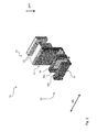
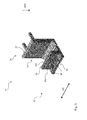
- the Fig. 1 . 2 and 4 show a first embodiment of a guide device according to the invention 10. This is equipped with a mounting portion 20 and a guide portion 30.
- the attachment portion 20 is here designed for a clamping and positive fastening to the first door leaf 112 of the sliding door 110.
- two fastening surfaces 22 are provided, which can be brought into contact with two different sides of the door leaf 112. Subsequently, a corresponding attachment can be provided by clamping action.
- Fig. 1 shows the situation in which the guide device 10 is attached to the first door leaf 112.
- the two door leaves 112 and 114 in this case have parallel directions of movement BR.
- SKR In the direction of gravity SKR at the lower end of the two door leaves 112 and 114 is thereby the arrangement of this guide device 10th
- the guide section 30 here has two guide surfaces 32a and 32b of the guide surface 32. Also, sliding portions 38 are provided on the two guide surfaces 32a and 32b, which act here friction-minimizing for the surface of the door leaf 114. Again Fig. 4 can be seen well, a non-contact leadership takes place.
- a guide gap is provided both in a horizontal manner and in a vertical manner. In particular, the horizontal guide gap is crucial in order to be able to release the typical movement without oscillation of the second door leaf 114.
- the two guide surfaces 32a and 32b have a guide spacing 34 which is greater than the thickness of the second door leaf 114.
- a first variation device 40 is provided, which is able to perform the movement of the guide portion 30 against the direction of gravity SKR upward or in the direction of gravity SKR down. This allows an adjustment of the vertical guide gap according to Fig. 4 to be able to make.
- a second variation device 50 is provided. This allows the entire guide section 30 to be displaced transversely to the direction of gravity SKR and transversely to the direction of movement BR here in the form of a dovetail guide.
- the gap which is set between the two door leaves 112 and 114, can be varied in this way and thus be simulated by the guide section 30.
- a guide interface 60 is provided so that different guide portions 30 can be exchanged interchangeable with the attachment portion 20.
- Fig. 3 shows that now the original guide portion 30 of the Fig. 1 to 4 has been removed and in its place on the dovetail guide of the guide interface 60, a corresponding guide web 36 has been pushed. The two guide surfaces 32a and 32b are now able to engage in a corresponding inner guide groove of the second door leaf 114.
- Fig. 5 to 7 now show the possibilities of movement of the individual door leaves 112 and 114.
- Fig. 4 close in a telescopic manner, the two door leaves 112 and 114 of the sliding door 110 to the closed position according to Fig. 7 ,
- An unillustrated roller carriage runs in a roller track 120 above a door opening.
- Fig. 8 shows that also in the direction of movement BR an offset V between the mounting portion 20 and the guide portion 30 is possible.
- this offset V is preferably limited to a residual overlap of about 3-5% of the two surfaces 32 and 22, in order to provide in this way the transmission of the executives with the lowest possible lever arm. This reduces the mechanical impairment in the transmission of such executives.
Landscapes
- Engineering & Computer Science (AREA)
- Mechanical Engineering (AREA)
- Support Devices For Sliding Doors (AREA)
- Closing And Opening Devices For Wings, And Checks For Wings (AREA)
Abstract
Description
- Die vorliegende Erfindung betrifft eine Führungsvorrichtung für die Führung eines Türblatts einer Schiebetür sowie eine Schiebetürenanlage.
- Es ist bekannt, dass Schiebetüren eingesetzt werden, um Türöffnungen in verschiedener Weise zu öffnen und zu verschließen. Bei großen Türöffnungen und/oder bei wenig Platz neben der Türöffnung sind dabei häufig sogenannte Teleskoplösungen eingesetzt. Das bedeutet, dass eine solche Schiebetür zumindest zwei Türblätter aufweist, welche in teleskopierender Weise sich zueinander bewegen können. In der geöffneten Position überlappen dabei die beiden Türblätter insbesondere vollständig, während in geschlossener Position diese Überlappung auf ein Minimum reduziert wird. Das bedeutet, dass während der Ausfahrbewegung eines der beiden Türblätter sich schneller bewegt, als das andere der beiden Türblätter. Daher können die beiden Türblätter auch als Schnellläufer und Langsamläufer bezeichnet werden. Um eine definierte Bewegung zur Verfügung stellen zu können, sind die Türblätter üblicherweise in Rollenwagen befestigt, welche in einer Rollenlaufbahn verschiebbar gelagert sind. Diese Rollenlaufbahn ist oberhalb der Türöffnung befestigt. Jedoch besteht weiterhin die Gefahr, dass die Unterkante der beiden Türblätter eine Pendelbewegung quer zur Bewegungsrichtung der Türblätter ausführen kann. Deswegen ist bei bekannten Schiebetürenanlagen eine Führungsvorrichtung auf dem Boden befestigt, welche mit entsprechenden Führungsflächen diese Pendelbewegung verhindert oder eingrenzt.
- Nachteilhaft bei den bekannten Lösungen ist genau diese fest fixierte Führungsvorrichtung. So ist diese am Boden befestigt, wodurch dementsprechend eine Beeinflussung des Bodens bzw. eine Vorbereitung des Bodens notwendig wird. Auch führt dies dazu, dass die Gefahr einer Stolperschwelle entsteht, wenn sich die Bodenführung außer Eingriff mit einem Türblatt befindet. Nicht zuletzt sind die Montagepositionen eingeschränkt hinsichtlich der Ortswahl für eine solche Führungsvorrichtung.
- Es ist Aufgabe der vorliegenden Erfindung, die voranstehend beschriebenen Nachteile zumindest teilweise zu beheben. Insbesondere ist es Aufgabe der vorliegenden Erfindung, in kostengünstiger und einfacher Weise die Bodenführung der Türblätter zu verbessern und insbesondere die Montage und/oder die Einstellbarkeit zu erleichtern.
- Voranstehende Aufgabe wird gelöst durch eine Führungsvorrichtung mit den Merkmalen des Anspruchs 1 sowie eine Schiebetürenanlage mit den Merkmalen des Anspruchs 12. Weitere Merkmale und Details der Erfindung ergeben sich aus den Unteransprüchen, der Beschreibung und den Zeichnungen. Dabei gelten Merkmale und Details, die im Zusammenhang mit der erfindungsgemäßen Führungsvorrichtung beschrieben sind, selbstverständlich auch im Zusammenhang mit der erfindungsgemäßen Schiebetürenanlage und jeweils umgekehrt, so dass bezüglich der Offenbarung zu den einzelnen Erfindungsaspekten stets wechselseitig Bezug genommen wird bzw. werden kann.
- Eine erfindungsgemäße Führungsvorrichtung dient der Führung eines Türblatts einer Schiebetür. Hierfür weist die Führungsvorrichtung einen Befestigungsabschnitt für die Befestigung an einem bewegbaren ersten Türblatt der Schiebetür auf. Weiter ist ein Führungsabschnitt mit wenigstens einer Führungsfläche für die Führung eines relativ zum ersten Türblatt bewegbaren zweiten Türblatts der Schiebetür vorgesehen.
- Entscheidend im Vergleich zu den bekannten Lösungen ist es nun, dass die Führungsvorrichtung als bewegbare bzw. mitfahrende Führungsvorrichtung ausgebildet ist. Um dies zu gewährleisten, ist der Befestigungsabschnitt vorgesehen. Mithilfe des Befestigungsabschnittes ist eine Befestigung am ersten Türblatt möglich. Beim ersten Türblatt handelt es sich dabei insbesondere um den Langsamläufer einer Teleskopausführung einer Schiebetür. Das bedeutet, dass während der Bewegung dieses ersten Türblattes zwischen einer Offen-Position und einer Schließposition sich in gleichem Maße der Befestigungsabschnitt und damit die gesamte Führungsvorrichtung mitbewegt. Die Bewegungsstrecke der Schiebetür ist als dementsprechend identisch mit der Bewegungsstrecke der Führungsvorrichtung.
- Darüber hinaus ist neben dem Befestigungsabschnitt ein Führungsabschnitt vorgesehen. Dieser weist eine Führungsfläche für die Führung des zweiten Türblatts auf. Das zweite Türblatt ist dabei vorzugsweise als Schnellläufer der als Teleskopanlage ausgebildeten Schiebetürenanlage vorgesehen. Das bedeutet, dass eine Relativbewegung zwischen dem ersten Türblatt und dem zweiten Türblatt stattfindet. Bewegt sich die Schiebetür aus der Geschlossen-Position in die Öffnungsposition, so bewegt sich das zweite Türblatt mit einer höheren Geschwindigkeit und damit relativ zu dem sich langsamer bewegenden ersten Türblatt. Aufgrund der Tatsache, dass sich zusammen mit dem ersten Türblatt auch die Führungsvorrichtung bewegt, findet die identische Relativbewegung auch zwischen der Führungsvorrichtung und dem zweiten Türblatt statt. Dies führt dementsprechend auch zu einer Relativbewegung zwischen der wenigstens einen Führungsfläche und dem zweiten Türblatt.
- Eine Führungsfläche zur Führung ist vorzugsweise als ebene Fläche ausgebildet. Sie bildet dabei die entsprechende ebene Oberfläche des zweiten Türblatts nach. Dabei kann eine Führung sowohl kontaktierend, als auch kontaktfrei ausgebildet sein. Bevorzugt ist zwischen der Führungsfläche und der Oberfläche des zweiten Türblatts ein Bewegungsspalt ausgebildet, welcher im Normalfall eine Kontaktierung zwischen Führungsfläche und Türblatt vermeidet. Nur für den Fall, dass eine mechanische Einflussnahme auf das zweite Türblatt quer zur Bewegungsrichtung dieses zweiten Türblattes stattfindet, würde dieses Türblatt sozusagen gegen die Führungsfläche gedrückt. Die Führungsfläche vermeidet dabei eine Weiterbewegung des Türblattes über diesen Bewegungsspalt hinaus und verhindert auf diese Weise eine sich ansonsten einstellende Pendelbewegung des Türblatts. Wie aus dieser Erläuterung eindeutig wird, ist vorzugsweise nicht nur wenigstens eine Führungsfläche vorgesehen, sondern bevorzugt auf beiden Seiten des Türblattes zumindest eine Führungsfläche eingesetzt.
- Im Gegensatz zu den bekannten Lösungen, bei welchen im Wesentlichen ausschließlich ein Führungsabschnitt am Boden befestigt wird, ist die erfindungsgemäße Funktionalität der Führung des zweiten Türblattes nun vollständig unabhängig von jeglicher Bodenbefestigung. Vielmehr bewegt sich die gesamte Führungsvorrichtung mit dem ersten Türblatt mit und befindet sich auf diese Weise automatisch immer in einer idealen Position für die Führung des zweiten Türblatts. Die Positionierung und damit die gesamte Führungsqualität für die Führung des zweiten Türblatts steigt damit im Vergleich zu den festpositionierten bekannten Führungsvorrichtungen deutlich an.
- Darüber hinaus wird die Montage deutlich vereinfacht. Insbesondere kann der Befestigungsabschnitt auf eine definiert positionierte Befestigung an dem ersten Türblatt vorgesehen bzw. ausgerichtet sein. Damit wird bereits die Montage vereinfacht, da kein Abmessen, Ausrichten und Vorbereiten einer Bodenplatte unterhalb der Schiebetür mehr notwendig ist.
- Sollte darüber hinaus noch eine Einstellbarkeit der Führungsfläche bzw. des Führungsabschnitts notwendig sein, so wird dies ebenfalls vereinfacht, da nicht mehr mit Keilen oder Unterlegscheiben an einer Bodenfläche eine entsprechende manuelle Einstellung erforderlich ist.
- Es kann von Vorteil sein, wenn bei einer erfindungsgemäßen Führungsvorrichtung der Befestigungsabschnitt eine Befestigungsfläche zur Anlage an dem ersten Türblatt aufweist, welche insbesondere zumindest abschnittsweise parallel zur Führungsfläche ausgerichtet ist. Vorzugsweise befinden sich bei einer Schiebetürenanlage in Teleskopausrichtung die beiden Türblätter parallel oder im Wesentlichen parallel zueinander angeordnet. Ist die Befestigungsfläche insbesondere ebenfalls als ebene Befestigungsfläche ausgebildet, so bildet die Korrelation zwischen der wenigstens einen Befestigungsfläche und der wenigstens einen Führungsfläche zueinander die Korrelation der beiden Türblätter zueinander nach. Durch eine flächige Anlage der Befestigungsfläche bzw. des Befestigungsabschnitts am ersten Türblatt wird darüber hinaus die Krafteinwirkung verbessert. Da als Türblätter häufig Glas bzw. Holz eingesetzt eingesetzt werden als Material für das jeweilige Türblatt ist eine flächige Übertragung der Befestigungskräfte bzw. der Führungskräfte von großem Vorteil. Insbesondere kann die Befestigungsfläche als klemmende Befestigung ausgebildet sein, um eine mechanische Bearbeitung des jeweiligen Türblatts zu reduzieren oder sogar vollständig vermeiden zu können.
- Ein weiterer Vorteil kann es sein, wenn bei einer erfindungsgemäßen Führungsvorrichtung die Befestigungsfläche und die Führungsfläche zueinander einen maximalen Versatz in Bewegungsrichtung des zweiten Türblatts aufweisen, welcher kleiner ist als die Erstreckung der Befestigungsfläche und/oder der Führungsfläche. Die Bewegungsrichtung ist dabei bezogen auf das jeweilige Türblatt und wird definiert durch die Ausrichtung der Führungsfläche. Dementsprechend ist bei einer flächigen bzw. ebenen Ausrichtung der Führungsfläche auch gleichzeitig die Bewegungsrichtung des zweiten Türblatts in definierter Weise eindeutig vorgegeben. Ein Versatz von Befestigungsfläche und Führungsfläche zueinander führt zu einer Übertragung der Führungskräfte in Form von Drehmomenten. Es muss also für diesen Versatz ein Abstützen der Führungskräfte in drehmomentabstützender Weise vorgesehen werden. Je geringer dieser maximale Versatz ausgebildet ist, umso kleiner ist der Hebelarm, welcher durch die entsprechende Führungskraft von der Führungsfläche auf die Befestigungsfläche übertragen wird. Eine Reduktion des maximalen Versatzes im Rahmen dieser Ausführungsform führt dementsprechend zu geringeren übertragenen Kräften bzw. zu geringerer mechanischer Belastung im Bereich der Befestigungsfläche. Dabei ist vorzugsweise in Richtung der Bewegungsrichtung des zweiten Türblatts eine Mindestüberlappung von ca. 3-5 % der Befestigungsfläche mit der Führungsfläche vorgesehen. Ein entsprechendes Kippmoment bei der Abstützung von Führungskräften wird auf diese Weise reduziert. Führungskräfte treten dabei insbesondere dann auf, wenn eine durch mechanische Einwirkung auf das zweite Türblatt entstehende Pendelbewegung durch die Führungsfläche in kraftschlüssiger Weise aufgefangen wird.
- Ein weiterer Vorteil ist erzielbar, wenn bei einer erfindungsgemäßen Führungsvorrichtung der Befestigungsabschnitt und/oder der Führungsabschnitt eine erste Variationsvorrichtung aufweist, für eine Variation der Position des Befestigungsabschnitts relativ zum Führungsabschnitt in Schwerkraftrichtung. Mit anderen Worten kann sich der Führungsabschnitt durch die erste Variationsvorrichtung senkrecht nach oben oder senkrecht nach unten bzw. quer nach oben oder quer nach unten bewegen lassen. Zwischen dem Führungsabschnitt bildet sich dabei zwischen einer horizontalen Fläche des Führungsabschnitts und der Unterseite bzw. der Unterkante des zweiten Türblatts ein Führungsspalt aus. Dieser kann auch als senkrechter bzw. vertikaler Führungsspalt bezeichnet werden. Auch hier ist es bevorzugt, wenn eine kontaktfreie Führung stattfindet. Um dies zu gewährleisten und gleichzeitig diesen senkrechten Führungsspalt hinsichtlich seiner maximalen Erstreckung zu begrenzen, kann nun die erste Variationsvorrichtung diesen Führungsabschnitt nach oben fahren und auf diese Weise den senkrechten Führungsspalt bzw. den vertikalen Führungsspalt reduzieren. Ein Aufsetzen und ein entsprechendes Schleifen werden damit deutlich reduziert. Eine solche erste Variationsvorrichtung kann zum Beispiel als Langloch ausgebildet sein, welches durch entsprechende Klemmwirkung von Befestigungsmitteln eine Fixierung in der gewünschten Variationsposition erlaubt. Auch komplexere Lösungen, zum Beispiel mithilfe von Gewindevorrichtungen zur Verstellung bzw. zur Variation sind im Rahmen dieser Ausführungsform denkbar.
- Ein weiterer Vorteil kann es sein, wenn bei einer erfindungsgemäßen Führungsvorrichtung der Befestigungsabschnitt und/oder der Führungsabschnitt eine zweite Variationsvorrichtung aufweist, für eine Variation der Position des Befestigungsabschnitts relativ zum Führungsabschnitt quer zur Schwerkraftrichtung und/oder der Bewegungsrichtung des zweiten Türblatts. Diese zweite Variationsvorrichtung kann alternativ oder zusätzlich zur ersten Variationsvorrichtung eingesetzt werden. Diese zweite Variationsvorrichtung kann sowohl eine, als auch zwei Variationsrichtungen zur Verfügung stellen. Quer zur Schwerkraftrichtung ist dabei insbesondere eine Bewegung entlang der Bewegungsrichtung oder quer zur Bewegungsrichtung. Auch in beiden Richtungen ist eine Variation durch die zweite Variationsvorrichtung denkbar. So können ein Versatz in der Bewegungsrichtung und ein sich auf diese Weise einstellendes Kippmoment bei der Abstützung von Führungskräften eingestellt werden. Ein seitlicher Versatz erlaubt es, den seitlichen bzw. den waagerechten Führungsspalt einzustellen und hinsichtlich einer kontaktfreien Normalbewegung des zweiten Türblattes auszurichten. Auch kann auf diese Weise eine Anpassung an entsprechend unterschiedliche Stärken des jeweils zweiten Türblattes erfolgen.
- Vorteilhaft ist es weiter, wenn bei einer erfindungsgemäßen Führungsvorrichtung der Führungsabschnitt zwei Führungsflächen aufweist, welche parallel zueinander ausgerichtet sind und einen Führungsabstand aufweisen, welcher größer als die Breite des zu führenden zweiten Türblatts ausgebildet ist. Eine vorzugsweise vorhandene dritte Variationsvorrichtung kann vorgesehen werden, um den Führungsabstand zu variieren und auf diese Weise an unterschiedliche waagerechte Führungsspalte bzw. unterschiedliche Stärken des zweiten Türblatts anzupassen. Die Führung von beiden Seiten erlaubt es, eine Pendelbewegung des zweiten Türblatts auch in diesen beiden Richtungen quer zur Bewegungsrichtung zu minimieren bzw. zu verhindern. Insbesondere erfolgt dieses seitliche Umfassen bei Glastüren für das zweite Türblatt. Die später noch beschriebenen Gleiteinsätze auf der jeweiligen Führungsfläche können vorgesehen werden, um verschleißarmes Abgleiten des zweiten Türblattes im Falle eines Kontakts gewährleisten zu können.
- Vorteilhaft ist es darüber hinaus, wenn bei einer erfindungsgemäßen Führungsvorrichtung zwei Führungsflächen als zwei Seiten eines Führungsstegs ausgebildet sind für einen Eingriff in eine Führungsnut des zweiten Türblatts zur beidseitigen Führung des zweiten Türblatts. Insbesondere bei spanend bearbeitbaren Materialien des zweiten Türblatts können auf diese Weise das Gewicht und die geometrische Erstreckung der Führungsvorrichtung reduziert werden. Ein Führungssteg greift sozusagen unsichtbar in eine innenliegende Führungsnut des zweiten Türblatts an dessen Unterkante ein. Damit wird eine beidseitige Führung gegen Pendelbewegungen in beide Richtungen gewährleistet. Gleichzeitig wird sichergestellt, dass ein entsprechender Bewegungsspalt ebenfalls in beiden Seiten in waagerechter Ausrichtung zu den Seitenwandungen der Führungsnut gewährleistet wird. Eine ebenfalls dritte Variationsvorrichtung ist denkbar, um die Breite des Führungssteges und damit wiederum die waagerechte Ausbildung des Führungsspaltes einstellbar zu machen.
- Vorteilhaft ist es weiter, wenn bei einer erfindungsgemäßen Führungsvorrichtung der Befestigungsabschnitt und der Führungsabschnitt entlang der Bewegungsrichtung des zweiten Türblatts eine gleiche oder im Wesentlichen gleiche geometrische Erstreckung aufweisen. Insbesondere ist dies der Fall, wenn der Versatz zwischen Befestigungsabschnitt und Führungsabschnitt null oder im Wesentlichen null ist. Damit wird eine Einbringung von Kippmomenten vorzugsweise vollständig verhindert.
- Ein weiterer Vorteil ist es darüber hinaus, wenn bei einer erfindungsgemäßen Führungsvorrichtung der Führungsabschnitt reversibel an dem Befestigungsabschnitt befestigt ist mittels einer Führungsschnittstelle. Mit anderen Worten ist der Führungsabschnitt austauschbar über die Führungsschnittstelle befestigt. So kann je nach Einsatzsituation, zum Beispiel in Abhängigkeit des Materials des zweiten Türblatts, ein entsprechend spezifisch ausgebildeter Führungsabschnitt eingesetzt werden. Die Führungsschnittstelle kann dabei einen Formschluss, einen Reibschluss und/oder einen Kraftschluss für die Befestigung aufweisen. Somit sind auch unterschiedliche Materialien der einzelnen Türblätter frei miteinander kombinierbar, ohne die Funktionalität einer erfindungsgemäßen Führungsvorrichtung zu beeinträchtigen.
- Ebenfalls von Vorteil kann es sein, wenn bei einer erfindungsgemäßen Führungsvorrichtung der Führungsabschnitt und/oder der Befestigungsabschnitt einen Anschlag aufweisen für die Begrenzung der Bewegung des ersten und/oder des zweiten Türblatts. Dabei kann es sich insbesondere um ein elastisches Material handeln, welches in Richtung der Bewegungsrichtung den äußersten Abschnitt des Führungsabschnitts und/oder des Befestigungsabschnitts ausbildet. Der Anschlag ist jetzt in die Führungsvorrichtung integrierbar, so dass auf diese Weise an anderen Orten der Schiebetürenanlage ein entsprechendes Bauteil eingespart werden kann.
- Ein weiterer Vorteil ist es, wenn bei einer erfindungsgemäßen Führungsvorrichtung die Führungsfläche zumindest einen, insbesondere auswechselbaren, Gleitabschnitt aufweist, für ein Abgleiten des zweiten Türblatts. Ein solcher Gleitabschnitt kann als Verschleißteil ausgebildet sein, und eine gleitverbessernde bzw. reibminimierte Oberfläche bzw. Materialwahl aufweisen. So sind beispielsweise Teflonmaterialien oder hinsichtlich der Oberflächenrauigkeit reduzierte Ausbildungen im Sinne dieser Ausführungsform denkbar.
- Ebenfalls Gegenstand der vorliegenden Erfindung ist eine Schiebetürenanlage, aufweisend eine Rollenlaufbahn und wenigstens einen in der Rollenlaufbahn verschiebbar gelagerten Rollenwagen, an welchem ein erstes Türblatt befestigt ist. Weiter weist eine solche Schiebetürenanlage wenigstens einen weiteren in der Rollenlaufbahn verschiebbar gelagerten Rollenwagen auf, an welchem ein zweites Türblatt befestigt ist. Dabei ist zur Führung der Bewegung des zweiten Türblattes an dem ersten Türblatt eine Führungsvorrichtung gemäß der vorliegenden Erfindung befestigt. Auf diese Weise bringt eine erfindungsgemäße Schiebetürenanlage die gleichen Vorteile mit sich, wie sie ausführlich mit Bezug auf eine erfindungsgemäße Führungsvorrichtung erläutert worden sind.
- Weitere Vorteile, Merkmale und Einzelheiten der Erfindung ergeben sich aus der nachfolgenden Beschreibung, in der unter Bezugnahme auf die Zeichnungen Ausführungsbeispiele der Erfindung im Einzelnen beschrieben sind. Dabei können die in den Ansprüchen und in der Beschreibung erwähnten Merkmale jeweils einzeln für sich oder in beliebiger Kombination erfindungswesentlich sein. Es zeigen schematisch:
- Fig. 1
- eine Ausführungsform einer erfindungsgemäßen Führungsvorrichtung,
- Fig. 2
- die Ausführungsform der
Fig. 1 in unmontierter Darstellung, - Fig. 3
- eine weitere Ausführungsform einer erfindungsgemäßen Führungsvorrichtung,
- Fig. 4
- die Ausführungsform der
Fig. 1 und2 in seitlicher Einsatzdarstellung, - Fig. 5
- die Ausführungsform einer erfindungsgemäßen Schiebetürenanlage,
- Fig. 6
- die Schiebetürenanlage gemäß
Fig. 5 während der Schließbewegung, - Fig. 7
- die Schiebetürenanlage der
Fig. 5 und 6 in der Schließposition und - Fig. 8
- eine Möglichkeit eines maximalen Versatzes einer erfindungsgemäßen Führungsvorrichtung.
- Die
Fig. 1 ,2 und4 zeigen eine erste Ausführungsform einer erfindungsgemäßen Führungsvorrichtung 10. Diese ist mit einem Befestigungsabschnitt 20 und einem Führungsabschnitt 30 ausgestattet. Der Befestigungsabschnitt 20 ist hier für eine klemmende und formschlüssige Befestigung an dem ersten Türblatt 112 der Schiebetür 110 ausgebildet. Dafür sind zwei Befestigungsflächen 22 vorgesehen, welche von zwei unterschiedlichen Seiten des Türblatts 112 zur Anlage gebracht werden können. Anschließend kann durch Klemmwirkung eine entsprechende Befestigung zur Verfügung gestellt werden. -
Fig. 1 zeigt die Situation, bei welcher die Führungsvorrichtung 10 am ersten Türblatt 112 befestigt ist. Die beiden Türblätter 112 und 114 weisen dabei parallele Bewegungsrichtungen BR auf. In Schwerkraftrichtung SKR am unteren Ende der beiden Türblätter 112 und 114 befindet sich dabei die Anordnung dieser Führungsvorrichtung 10. - Um die Führungsfunktionalität zur Verfügung stellen zu können, weist der Führungsabschnitt 30 hier zwei Führungsflächen 32a und 32b der Führungsfläche 32 auf. Auch sind an den beiden Führungsflächen 32a und 32b Gleitabschnitte 38 vorgesehen, welche hier reibungsminimierend für die Oberfläche des Türblattes 114 wirken. Wie der
Fig. 4 gut zu entnehmen ist, findet eine kontaktfreie Führung statt. So ist sowohl in waagerechter Weise als auch in senkrechter Weise ein Führungsspalt vorgesehen. Insbesondere ist dabei der waagerechte Führungsspalt entscheidend, um die typische Bewegung ohne ein Pendeln des zweiten Türblatts 114 freigegeben zu können. Hierfür weisen die beiden Führungsflächen 32a und 32b einen Führungsabstand 34 auf, welcher größer ist, als die Stärke des zweiten Türblatts 114. - Die Ausführungsform der
Fig. 1 bis 4 ist mit hohen Variationsmöglichkeiten versehen. So ist hier eine erste Variationsvorrichtung 40 vorgesehen, welche in der Lage ist, die Bewegung des Führungsabschnitts 30 entgegen der Schwerkraftrichtung SKR nach oben oder in Richtung der Schwerkraftrichtung SKR nach unten durchzuführen. Dies erlaubt es, eine Einstellung des senkrechten Führungsspaltes gemäßFig. 4 vornehmen zu können. Zusätzlich ist eine zweite Variationsvorrichtung 50 vorgesehen. Diese erlaubt es, hier in Form einer Schwalbenschwanzführung den gesamten Führungsabschnitt 30 quer zur Schwerkraftrichtung SKR sowie quer zur Bewegungsrichtung BR zu verschieben. Der Spalt, welcher sich zwischen den beiden Türblättern 112 und 114 einstellt, kann auf diese Weise variiert werden und damit durch den Führungsabschnitt 30 nachgebildet werden. - Wie der
Fig. 3 zu entnehmen ist, ist darüber hinaus eine Führungsschnittstelle 60 vorgesehen, so dass unterschiedliche Führungsabschnitte 30 austauschbar mit dem Befestigungsabschnitt 20 kombiniert werden können.Fig. 3 zeigt, dass nun der ursprüngliche Führungsabschnitt 30 derFig. 1 bis 4 entfernt worden ist und an dessen Stelle auf die Schwalbenschwanzführung der Führungsschnittstelle 60 ein entsprechender Führungssteg 36 aufgeschoben worden ist. Die beiden Führungsflächen 32a und 32b sind nun in der Lage, in eine entsprechend innenliegende Führungsnut des zweiten Türblatts 114 einzugreifen. - Die
Fig. 5 bis 7 zeigen nun die Möglichkeiten der Bewegung der einzelnen Türblätter 112 und 114. Ausgehend von der geöffneten Situation gemäßFig. 4 schließen sich in teleskopierender Weise die beiden Türblätter 112 und 114 der Schiebetür 110 bis zur Schließposition gemäßFig. 7 . Ein nicht dargestellter Rollenwagen läuft dabei in einer Rollenlaufbahn 120 oberhalb einer Türöffnung. -
Fig. 8 zeigt, dass auch in der Bewegungsrichtung BR ein Versatz V zwischen dem Befestigungsabschnitt 20 und dem Führungsabschnitt 30 möglich ist. Jedoch ist dieser Versatz V vorzugsweise auf eine Restüberlappung von ca. 3-5 % der beiden Flächen 32 und 22 begrenzt, um auf diese Weise die Übertragung der Führungskräfte mit einem möglichst geringen Hebelarm zu versehen. Dies reduziert die mechanische Beeinträchtigung bei der Übertragung solcher Führungskräfte. - Die voranstehende Erläuterung der Ausführungsformen beschreibt die vorliegende Erfindung ausschließlich im Rahmen von Beispielen. Selbstverständlich können einzelne Merkmale der Ausführungsformen, sofern technisch sinnvoll, frei miteinander kombiniert werden, ohne den Rahmen der vorliegenden Erfindung zu verlassen.
-
- 10
- Führungsvorrichtung
- 20
- Befestigungsabschnitt
- 22
- Befestigungsfläche
- 30
- Führungsabschnitt
- 32
- Führungsfläche
- 32a
- Führungsfläche
- 32b
- Führungsfläche
- 34
- Führungsabstand
- 36
- Führungssteg
- 38
- Gleitabschnitt
- 40
- erste Variationsvorrichtung
- 50
- zweite Variationsvorrichtung
- 60
- Führungsschnittstelle
- 70
- Anschlag
- 100
- Schiebetürenanlage
- 110
- Schiebetür
- 112
- Türblatt
- 114
- Türblatt
- 120
- Rollenlaufbahn
- V
- Versatz
- BR
- Bewegungsrichtung
- SKR
- Schwerkraftrichtung
Claims (12)
- Führungsvorrichtung (10) für die Führung eines Türblatts (112, 114) einer Schiebetür (110), aufweisend einen Befestigungsabschnitt (20) für die Befestigung an einem bewegbaren ersten Türblatt (112) der Schiebetür (110) und einen Führungsabschnitt (30) mit wenigstens einer Führungsfläche (32) für die Führung eines relativ zum ersten Türblatt (112) bewegbaren zweiten Türblatts (114) der Schiebetür (110).
- Führungsvorrichtung (10) nach Anspruch 1, dadurch gekennzeichnet, dass der Befestigungsabschnitt (20) eine Befestigungsfläche (22) zur Anlage an dem ersten Türblatt (112) aufweist, welche insbesondere zumindest abschnittsweise parallel zur Führungsfläche (32) ausgerichtet ist.
- Führungsvorrichtung (10) nach Anspruch 2, dadurch gekennzeichnet, dass die Befestigungsfläche (22) und die Führungsfläche (32) zueinander einen maximalen Versatz (V) in Bewegungsrichtung (BR) des zweiten Türblatts (114) aufweisen, welcher kleiner ist als die Erstreckung der Befestigungsfläche (22) und/oder der Führungsfläche (42).
- Führungsvorrichtung (10) nach einem der voranstehenden Ansprüche, dadurch gekennzeichnet, dass der Befestigungsabschnitt (20) und/oder der Führungsabschnitt (30) eine erste Variationsvorrichtung (40) aufweist für eine Variation der Position des Befestigungsabschnitts (20) relativ zum Führungsabschnitt (30) in Schwerkraftrichtung (SKR).
- Führungsvorrichtung (10) nach einem der voranstehenden Ansprüche, dadurch gekennzeichnet, dass der Befestigungsabschnitt (20) und/oder der Führungsabschnitt (30) eine zweite Variationsvorrichtung (50) aufweist für eine Variation der Position des Befestigungsabschnitts (20) relativ zum Führungsabschnitt (30) quer zur Schwerkraftrichtung (SKR) und/oder der Bewegungsrichtung (BR) des zweiten Türblatts (114).
- Führungsvorrichtung (10) nach einem der voranstehenden Ansprüche, dadurch gekennzeichnet, dass der Führungsabschnitt (30) zwei Führungsflächen (32a, 32b) aufweist, welche parallel zueinander ausgerichtet sind und einen Führungsabstand (34) aufweisen, welcher größer als die Breite des zu führenden zweiten Türblattes (114) ausgebildet ist.
- Führungsvorrichtung (10) nach einem der voranstehenden Ansprüche, dadurch gekennzeichnet, dass zwei Führungsflächen (32a, 32b) als zwei Seiten eines Führungsstegs (36) ausgebildet sind für einen Eingriff in eine Führungsnut des zweiten Türblattes (114) zur beidseitigen Führung des zweiten Türblattes (114).
- Führungsvorrichtung (10) nach einem der voranstehenden Ansprüche, dadurch gekennzeichnet, dass der Befestigungsabschnitt (20) und der Führungsabschnitt (30) entlang der Bewegungsrichtung (BR) des zweiten Türblattes (114) eine gleiche oder im Wesentlichen gleiche geometrische Erstreckung aufweisen.
- Führungsvorrichtung (10) nach einem der voranstehenden Ansprüche, dadurch gekennzeichnet, dass der Führungsabschnitt (30) reversibel an dem Befestigungsabschnitt (20) befestigt ist mittels einer Führungsschnittstelle (60).
- Führungsvorrichtung (10) nach einem der voranstehenden Ansprüche, dadurch gekennzeichnet, dass der Führungsabschnitt (30) und/oder der Befestigungsabschnitt (20) einen Anschlag (70) aufweisen für die Begrenzung der Bewegung des ersten und/oder des zweiten Türblatts (112, 114).
- Führungsvorrichtung (10) nach einem der voranstehenden Ansprüche, dadurch gekennzeichnet, dass die Führungsfläche (32) zumindest einen, insbesondere auswechselbaren, Gleitabschnitt (38) aufweist, für ein Abgleiten des zweiten Türblattes (114).
- Schiebetürenanlage (100), aufweisend eine Rollenlaufbahn (120) und wenigstens einen in der Rollenlaufbahn (120) verschiebbar gelagerten Rollenwagen an welchem ein erstes Türblatt (112) befestigt ist, weiter aufweisend wenigstens einen weiteren in der Rollenlaufbahn (120) verschiebbar gelagerten Rollenwagen an welchem ein zweites Türblatt (114) befestigt ist, wobei zur Führung der Bewegung des zweiten Türblattes (114) an dem ersten Türblatt (112) eine Führungsvorrichtung (10) mit den Merkmalen eines der Ansprüche 1 bis 11 befestigt ist.
Priority Applications (2)
| Application Number | Priority Date | Filing Date | Title |
|---|---|---|---|
| ES15151190T ES2922306T3 (es) | 2015-01-14 | 2015-01-14 | Dispositivo guía para el guiado de una hoja de puerta de una puerta corredera |
| EP15151190.4A EP3045630B1 (de) | 2015-01-14 | 2015-01-14 | Führungsvorrichtung für die führung eines türblatts einer schiebetür |
Applications Claiming Priority (1)
| Application Number | Priority Date | Filing Date | Title |
|---|---|---|---|
| EP15151190.4A EP3045630B1 (de) | 2015-01-14 | 2015-01-14 | Führungsvorrichtung für die führung eines türblatts einer schiebetür |
Publications (2)
| Publication Number | Publication Date |
|---|---|
| EP3045630A1 true EP3045630A1 (de) | 2016-07-20 |
| EP3045630B1 EP3045630B1 (de) | 2022-06-15 |
Family
ID=52347186
Family Applications (1)
| Application Number | Title | Priority Date | Filing Date |
|---|---|---|---|
| EP15151190.4A Revoked EP3045630B1 (de) | 2015-01-14 | 2015-01-14 | Führungsvorrichtung für die führung eines türblatts einer schiebetür |
Country Status (2)
| Country | Link |
|---|---|
| EP (1) | EP3045630B1 (de) |
| ES (1) | ES2922306T3 (de) |
Citations (6)
| Publication number | Priority date | Publication date | Assignee | Title |
|---|---|---|---|---|
| US2833346A (en) * | 1956-01-30 | 1958-05-06 | Acme Appliance Mfg Company | Sliding door assembly |
| US3529382A (en) * | 1968-11-15 | 1970-09-22 | Eastern Prod Corp | Wide opening sliding door construction for a lawn building or the like |
| US7458410B1 (en) * | 2003-11-28 | 2008-12-02 | Dan Bronner | Multiple door joining assembly |
| WO2011089065A2 (en) * | 2010-01-21 | 2011-07-28 | Pucci Saoro Srl | Door leaf system for closing and/or opening an entrance |
| DE202011003596U1 (de) * | 2011-02-24 | 2011-10-21 | KORALLE Sanitärprodukte GmbH | Schiebetürsystem und eine das Schiebetürsystem umfassende Duschkabine |
| EP2796649A1 (de) * | 2013-04-22 | 2014-10-29 | Logli Massimo S.P.A. | Schließsystem für einen Raum mittels Schiebewänden und Bausatz für die Montage des Systems |
Family Cites Families (1)
| Publication number | Priority date | Publication date | Assignee | Title |
|---|---|---|---|---|
| ES2246673B1 (es) | 2003-12-18 | 2007-02-16 | Klein Iberica, S.A. | Dispositivo para el accionamiento sincronizado de puertas correderas. |
-
2015
- 2015-01-14 ES ES15151190T patent/ES2922306T3/es active Active
- 2015-01-14 EP EP15151190.4A patent/EP3045630B1/de not_active Revoked
Patent Citations (6)
| Publication number | Priority date | Publication date | Assignee | Title |
|---|---|---|---|---|
| US2833346A (en) * | 1956-01-30 | 1958-05-06 | Acme Appliance Mfg Company | Sliding door assembly |
| US3529382A (en) * | 1968-11-15 | 1970-09-22 | Eastern Prod Corp | Wide opening sliding door construction for a lawn building or the like |
| US7458410B1 (en) * | 2003-11-28 | 2008-12-02 | Dan Bronner | Multiple door joining assembly |
| WO2011089065A2 (en) * | 2010-01-21 | 2011-07-28 | Pucci Saoro Srl | Door leaf system for closing and/or opening an entrance |
| DE202011003596U1 (de) * | 2011-02-24 | 2011-10-21 | KORALLE Sanitärprodukte GmbH | Schiebetürsystem und eine das Schiebetürsystem umfassende Duschkabine |
| EP2796649A1 (de) * | 2013-04-22 | 2014-10-29 | Logli Massimo S.P.A. | Schließsystem für einen Raum mittels Schiebewänden und Bausatz für die Montage des Systems |
Also Published As
| Publication number | Publication date |
|---|---|
| ES2922306T3 (es) | 2022-09-13 |
| EP3045630B1 (de) | 2022-06-15 |
Similar Documents
| Publication | Publication Date | Title |
|---|---|---|
| DE102009005441B4 (de) | Schiebetür | |
| DE102014220837B3 (de) | Laufwagen zum leichtgängigen Abstellen eines Schiebeflügels von einem festen Rahmen eines Fensters, einer Tür oder dergleichen | |
| EP2714568B1 (de) | Variierbare kabinentür-schachttür-kupplung | |
| EP3045628B1 (de) | Laufbahnvorrichtung für die verschiebbare Lagerung von wenigstens einem ersten Rollenwagen und zumindest einem zweiten Rollenwagen | |
| EP3201413B1 (de) | Beschlaganordnung | |
| DE102014103851B4 (de) | Rollenführung | |
| EP2495382B1 (de) | Vorrichtung zum Bewegen eines Flügels eines Fensters, einer Tür oder dergleichen | |
| EP2678507B1 (de) | Glasschiebetür | |
| EP3064698A1 (de) | Tor | |
| EP3045630B1 (de) | Führungsvorrichtung für die führung eines türblatts einer schiebetür | |
| DE202017105083U1 (de) | Türband mit Flügelstabilisierung | |
| EP3211164A1 (de) | Schiebetürsystem | |
| DE102011077631B4 (de) | Automatische Schiebetüranlage | |
| DE102010030709B4 (de) | Schiebetüranlage | |
| DE102015203812A1 (de) | Feder- und/oder Dämpferelement | |
| DE102012202981A1 (de) | Beschlag für einen parallel abstellbaren und in dieser Lage verschiebbaren Flügel eines Fensters, einer Tür oder dergleichen | |
| WO2016169889A1 (de) | Beschlag für eine schiebetür und verfahren zur montage eines führungsbeschlages | |
| DE102018202813C5 (de) | Mechanischer Auslöser | |
| DE102015122671A1 (de) | Beschlaganordnung mit rahmenseitigem Verstellelement | |
| DE102014004076B4 (de) | Spritzgussmaschine mit Sicherheitstür | |
| DE102014202797B3 (de) | Distanzhalter | |
| DE102012222200B4 (de) | Bewegungsbegrenzer für einen Flügel einer Schiebetür | |
| EP2549043B1 (de) | Tragsystem für eine Schiebetür | |
| DE102010012593B4 (de) | Rollenband für Türen aus Kunststoff oder Holz | |
| EP3095937A1 (de) | Anbindung für ein ortsveränderbares torblatt |
Legal Events
| Date | Code | Title | Description |
|---|---|---|---|
| PUAI | Public reference made under article 153(3) epc to a published international application that has entered the european phase |
Free format text: ORIGINAL CODE: 0009012 |
|
| AK | Designated contracting states |
Kind code of ref document: A1 Designated state(s): AL AT BE BG CH CY CZ DE DK EE ES FI FR GB GR HR HU IE IS IT LI LT LU LV MC MK MT NL NO PL PT RO RS SE SI SK SM TR |
|
| AX | Request for extension of the european patent |
Extension state: BA ME |
|
| STAA | Information on the status of an ep patent application or granted ep patent |
Free format text: STATUS: REQUEST FOR EXAMINATION WAS MADE |
|
| 17P | Request for examination filed |
Effective date: 20170117 |
|
| RAP1 | Party data changed (applicant data changed or rights of an application transferred) |
Owner name: DORMAKABA DEUTSCHLAND GMBH |
|
| RBV | Designated contracting states (corrected) |
Designated state(s): AL AT BE BG CH CY CZ DE DK EE ES FI FR GB GR HR HU IE IS IT LI LT LU LV MC MK MT NL NO PL PT RO RS SE SI SK SM TR |
|
| STAA | Information on the status of an ep patent application or granted ep patent |
Free format text: STATUS: EXAMINATION IS IN PROGRESS |
|
| 17Q | First examination report despatched |
Effective date: 20190409 |
|
| GRAP | Despatch of communication of intention to grant a patent |
Free format text: ORIGINAL CODE: EPIDOSNIGR1 |
|
| STAA | Information on the status of an ep patent application or granted ep patent |
Free format text: STATUS: GRANT OF PATENT IS INTENDED |
|
| INTG | Intention to grant announced |
Effective date: 20220113 |
|
| RIN1 | Information on inventor provided before grant (corrected) |
Inventor name: HOEHER, RALF |
|
| RAP1 | Party data changed (applicant data changed or rights of an application transferred) |
Owner name: DORMA-GLAS GMBH |
|
| GRAS | Grant fee paid |
Free format text: ORIGINAL CODE: EPIDOSNIGR3 |
|
| GRAA | (expected) grant |
Free format text: ORIGINAL CODE: 0009210 |
|
| STAA | Information on the status of an ep patent application or granted ep patent |
Free format text: STATUS: THE PATENT HAS BEEN GRANTED |
|
| AK | Designated contracting states |
Kind code of ref document: B1 Designated state(s): AL AT BE BG CH CY CZ DE DK EE ES FI FR GB GR HR HU IE IS IT LI LT LU LV MC MK MT NL NO PL PT RO RS SE SI SK SM TR |
|
| REG | Reference to a national code |
Ref country code: CH Ref legal event code: EP Ref country code: GB Ref legal event code: FG4D Free format text: NOT ENGLISH |
|
| REG | Reference to a national code |
Ref country code: IE Ref legal event code: FG4D Free format text: LANGUAGE OF EP DOCUMENT: GERMAN |
|
| REG | Reference to a national code |
Ref country code: DE Ref legal event code: R096 Ref document number: 502015015892 Country of ref document: DE |
|
| REG | Reference to a national code |
Ref country code: AT Ref legal event code: REF Ref document number: 1498508 Country of ref document: AT Kind code of ref document: T Effective date: 20220715 |
|
| REG | Reference to a national code |
Ref country code: NL Ref legal event code: FP |
|
| REG | Reference to a national code |
Ref country code: ES Ref legal event code: FG2A Ref document number: 2922306 Country of ref document: ES Kind code of ref document: T3 Effective date: 20220913 |
|
| REG | Reference to a national code |
Ref country code: LT Ref legal event code: MG9D |
|
| PG25 | Lapsed in a contracting state [announced via postgrant information from national office to epo] |
Ref country code: SE Free format text: LAPSE BECAUSE OF FAILURE TO SUBMIT A TRANSLATION OF THE DESCRIPTION OR TO PAY THE FEE WITHIN THE PRESCRIBED TIME-LIMIT Effective date: 20220615 Ref country code: NO Free format text: LAPSE BECAUSE OF FAILURE TO SUBMIT A TRANSLATION OF THE DESCRIPTION OR TO PAY THE FEE WITHIN THE PRESCRIBED TIME-LIMIT Effective date: 20220915 Ref country code: LT Free format text: LAPSE BECAUSE OF FAILURE TO SUBMIT A TRANSLATION OF THE DESCRIPTION OR TO PAY THE FEE WITHIN THE PRESCRIBED TIME-LIMIT Effective date: 20220615 Ref country code: HR Free format text: LAPSE BECAUSE OF FAILURE TO SUBMIT A TRANSLATION OF THE DESCRIPTION OR TO PAY THE FEE WITHIN THE PRESCRIBED TIME-LIMIT Effective date: 20220615 Ref country code: GR Free format text: LAPSE BECAUSE OF FAILURE TO SUBMIT A TRANSLATION OF THE DESCRIPTION OR TO PAY THE FEE WITHIN THE PRESCRIBED TIME-LIMIT Effective date: 20220916 Ref country code: FI Free format text: LAPSE BECAUSE OF FAILURE TO SUBMIT A TRANSLATION OF THE DESCRIPTION OR TO PAY THE FEE WITHIN THE PRESCRIBED TIME-LIMIT Effective date: 20220615 Ref country code: BG Free format text: LAPSE BECAUSE OF FAILURE TO SUBMIT A TRANSLATION OF THE DESCRIPTION OR TO PAY THE FEE WITHIN THE PRESCRIBED TIME-LIMIT Effective date: 20220915 |
|
| PG25 | Lapsed in a contracting state [announced via postgrant information from national office to epo] |
Ref country code: RS Free format text: LAPSE BECAUSE OF FAILURE TO SUBMIT A TRANSLATION OF THE DESCRIPTION OR TO PAY THE FEE WITHIN THE PRESCRIBED TIME-LIMIT Effective date: 20220615 Ref country code: LV Free format text: LAPSE BECAUSE OF FAILURE TO SUBMIT A TRANSLATION OF THE DESCRIPTION OR TO PAY THE FEE WITHIN THE PRESCRIBED TIME-LIMIT Effective date: 20220615 |
|
| PG25 | Lapsed in a contracting state [announced via postgrant information from national office to epo] |
Ref country code: SM Free format text: LAPSE BECAUSE OF FAILURE TO SUBMIT A TRANSLATION OF THE DESCRIPTION OR TO PAY THE FEE WITHIN THE PRESCRIBED TIME-LIMIT Effective date: 20220615 Ref country code: SK Free format text: LAPSE BECAUSE OF FAILURE TO SUBMIT A TRANSLATION OF THE DESCRIPTION OR TO PAY THE FEE WITHIN THE PRESCRIBED TIME-LIMIT Effective date: 20220615 Ref country code: RO Free format text: LAPSE BECAUSE OF FAILURE TO SUBMIT A TRANSLATION OF THE DESCRIPTION OR TO PAY THE FEE WITHIN THE PRESCRIBED TIME-LIMIT Effective date: 20220615 Ref country code: PT Free format text: LAPSE BECAUSE OF FAILURE TO SUBMIT A TRANSLATION OF THE DESCRIPTION OR TO PAY THE FEE WITHIN THE PRESCRIBED TIME-LIMIT Effective date: 20221017 Ref country code: EE Free format text: LAPSE BECAUSE OF FAILURE TO SUBMIT A TRANSLATION OF THE DESCRIPTION OR TO PAY THE FEE WITHIN THE PRESCRIBED TIME-LIMIT Effective date: 20220615 Ref country code: CZ Free format text: LAPSE BECAUSE OF FAILURE TO SUBMIT A TRANSLATION OF THE DESCRIPTION OR TO PAY THE FEE WITHIN THE PRESCRIBED TIME-LIMIT Effective date: 20220615 |
|
| PG25 | Lapsed in a contracting state [announced via postgrant information from national office to epo] |
Ref country code: PL Free format text: LAPSE BECAUSE OF FAILURE TO SUBMIT A TRANSLATION OF THE DESCRIPTION OR TO PAY THE FEE WITHIN THE PRESCRIBED TIME-LIMIT Effective date: 20220615 Ref country code: IS Free format text: LAPSE BECAUSE OF FAILURE TO SUBMIT A TRANSLATION OF THE DESCRIPTION OR TO PAY THE FEE WITHIN THE PRESCRIBED TIME-LIMIT Effective date: 20221015 |
|
| REG | Reference to a national code |
Ref country code: DE Ref legal event code: R026 Ref document number: 502015015892 Country of ref document: DE |
|
| PLBI | Opposition filed |
Free format text: ORIGINAL CODE: 0009260 |
|
| PLAX | Notice of opposition and request to file observation + time limit sent |
Free format text: ORIGINAL CODE: EPIDOSNOBS2 |
|
| PG25 | Lapsed in a contracting state [announced via postgrant information from national office to epo] |
Ref country code: AL Free format text: LAPSE BECAUSE OF FAILURE TO SUBMIT A TRANSLATION OF THE DESCRIPTION OR TO PAY THE FEE WITHIN THE PRESCRIBED TIME-LIMIT Effective date: 20220615 |
|
| 26 | Opposition filed |
Opponent name: GEZE GMBH Effective date: 20230228 |
|
| PG25 | Lapsed in a contracting state [announced via postgrant information from national office to epo] |
Ref country code: DK Free format text: LAPSE BECAUSE OF FAILURE TO SUBMIT A TRANSLATION OF THE DESCRIPTION OR TO PAY THE FEE WITHIN THE PRESCRIBED TIME-LIMIT Effective date: 20220615 |
|
| PGFP | Annual fee paid to national office [announced via postgrant information from national office to epo] |
Ref country code: AT Payment date: 20230120 Year of fee payment: 9 |
|
| PG25 | Lapsed in a contracting state [announced via postgrant information from national office to epo] |
Ref country code: SI Free format text: LAPSE BECAUSE OF FAILURE TO SUBMIT A TRANSLATION OF THE DESCRIPTION OR TO PAY THE FEE WITHIN THE PRESCRIBED TIME-LIMIT Effective date: 20220615 |
|
| PGFP | Annual fee paid to national office [announced via postgrant information from national office to epo] |
Ref country code: IT Payment date: 20230120 Year of fee payment: 9 Ref country code: DE Payment date: 20230123 Year of fee payment: 9 |
|
| PGFP | Annual fee paid to national office [announced via postgrant information from national office to epo] |
Ref country code: NL Payment date: 20230119 Year of fee payment: 9 |
|
| PLBB | Reply of patent proprietor to notice(s) of opposition received |
Free format text: ORIGINAL CODE: EPIDOSNOBS3 |
|
| PGFP | Annual fee paid to national office [announced via postgrant information from national office to epo] |
Ref country code: ES Payment date: 20230405 Year of fee payment: 9 |
|
| REG | Reference to a national code |
Ref country code: CH Ref legal event code: PL |
|
| GBPC | Gb: european patent ceased through non-payment of renewal fee |
Effective date: 20230114 |
|
| PG25 | Lapsed in a contracting state [announced via postgrant information from national office to epo] |
Ref country code: LU Free format text: LAPSE BECAUSE OF NON-PAYMENT OF DUE FEES Effective date: 20230114 |
|
| REG | Reference to a national code |
Ref country code: BE Ref legal event code: MM Effective date: 20230131 |
|
| PG25 | Lapsed in a contracting state [announced via postgrant information from national office to epo] |
Ref country code: LI Free format text: LAPSE BECAUSE OF NON-PAYMENT OF DUE FEES Effective date: 20230131 Ref country code: GB Free format text: LAPSE BECAUSE OF NON-PAYMENT OF DUE FEES Effective date: 20230114 Ref country code: CH Free format text: LAPSE BECAUSE OF NON-PAYMENT OF DUE FEES Effective date: 20230131 |
|
| PG25 | Lapsed in a contracting state [announced via postgrant information from national office to epo] |
Ref country code: FR Free format text: LAPSE BECAUSE OF NON-PAYMENT OF DUE FEES Effective date: 20230131 Ref country code: BE Free format text: LAPSE BECAUSE OF NON-PAYMENT OF DUE FEES Effective date: 20230131 |
|
| PG25 | Lapsed in a contracting state [announced via postgrant information from national office to epo] |
Ref country code: IE Free format text: LAPSE BECAUSE OF NON-PAYMENT OF DUE FEES Effective date: 20230114 |
|
| PG25 | Lapsed in a contracting state [announced via postgrant information from national office to epo] |
Ref country code: MC Free format text: LAPSE BECAUSE OF FAILURE TO SUBMIT A TRANSLATION OF THE DESCRIPTION OR TO PAY THE FEE WITHIN THE PRESCRIBED TIME-LIMIT Effective date: 20220615 |
|
| PG25 | Lapsed in a contracting state [announced via postgrant information from national office to epo] |
Ref country code: MC Free format text: LAPSE BECAUSE OF FAILURE TO SUBMIT A TRANSLATION OF THE DESCRIPTION OR TO PAY THE FEE WITHIN THE PRESCRIBED TIME-LIMIT Effective date: 20220615 |
|
| REG | Reference to a national code |
Ref country code: DE Ref legal event code: R119 Ref document number: 502015015892 Country of ref document: DE |
|
| REG | Reference to a national code |
Ref country code: NL Ref legal event code: MM Effective date: 20240201 |
|
| REG | Reference to a national code |
Ref country code: AT Ref legal event code: MM01 Ref document number: 1498508 Country of ref document: AT Kind code of ref document: T Effective date: 20240114 |
|
| PG25 | Lapsed in a contracting state [announced via postgrant information from national office to epo] |
Ref country code: DE Free format text: LAPSE BECAUSE OF NON-PAYMENT OF DUE FEES Effective date: 20240801 |
|
| PG25 | Lapsed in a contracting state [announced via postgrant information from national office to epo] |
Ref country code: NL Free format text: LAPSE BECAUSE OF NON-PAYMENT OF DUE FEES Effective date: 20240201 |
|
| PG25 | Lapsed in a contracting state [announced via postgrant information from national office to epo] |
Ref country code: AT Free format text: LAPSE BECAUSE OF NON-PAYMENT OF DUE FEES Effective date: 20240114 |
|
| PG25 | Lapsed in a contracting state [announced via postgrant information from national office to epo] |
Ref country code: NL Free format text: LAPSE BECAUSE OF NON-PAYMENT OF DUE FEES Effective date: 20240201 Ref country code: DE Free format text: LAPSE BECAUSE OF NON-PAYMENT OF DUE FEES Effective date: 20240801 Ref country code: AT Free format text: LAPSE BECAUSE OF NON-PAYMENT OF DUE FEES Effective date: 20240114 |
|
| PG25 | Lapsed in a contracting state [announced via postgrant information from national office to epo] |
Ref country code: BG Free format text: LAPSE BECAUSE OF FAILURE TO SUBMIT A TRANSLATION OF THE DESCRIPTION OR TO PAY THE FEE WITHIN THE PRESCRIBED TIME-LIMIT Effective date: 20220615 |
|
| PG25 | Lapsed in a contracting state [announced via postgrant information from national office to epo] |
Ref country code: BG Free format text: LAPSE BECAUSE OF FAILURE TO SUBMIT A TRANSLATION OF THE DESCRIPTION OR TO PAY THE FEE WITHIN THE PRESCRIBED TIME-LIMIT Effective date: 20220615 |
|
| RDAF | Communication despatched that patent is revoked |
Free format text: ORIGINAL CODE: EPIDOSNREV1 |
|
| PG25 | Lapsed in a contracting state [announced via postgrant information from national office to epo] |
Ref country code: IT Free format text: LAPSE BECAUSE OF NON-PAYMENT OF DUE FEES Effective date: 20240114 |
|
| REG | Reference to a national code |
Ref country code: ES Ref legal event code: FD2A Effective date: 20250228 |
|
| PG25 | Lapsed in a contracting state [announced via postgrant information from national office to epo] |
Ref country code: ES Free format text: LAPSE BECAUSE OF NON-PAYMENT OF DUE FEES Effective date: 20240115 |
|
| REG | Reference to a national code |
Ref country code: DE Ref legal event code: R103 Ref document number: 502015015892 Country of ref document: DE Ref country code: DE Ref legal event code: R064 Ref document number: 502015015892 Country of ref document: DE |
|
| RDAG | Patent revoked |
Free format text: ORIGINAL CODE: 0009271 |
|
| STAA | Information on the status of an ep patent application or granted ep patent |
Free format text: STATUS: PATENT REVOKED |
|
| REG | Reference to a national code |
Ref country code: CH Ref legal event code: PL |
|
| 27W | Patent revoked |
Effective date: 20250505 |
|
| PG25 | Lapsed in a contracting state [announced via postgrant information from national office to epo] |
Ref country code: CY Free format text: LAPSE BECAUSE OF FAILURE TO SUBMIT A TRANSLATION OF THE DESCRIPTION OR TO PAY THE FEE WITHIN THE PRESCRIBED TIME-LIMIT; INVALID AB INITIO Effective date: 20150114 |
|
| REG | Reference to a national code |
Ref country code: AT Ref legal event code: MA03 Ref document number: 1498508 Country of ref document: AT Kind code of ref document: T Effective date: 20250505 |
|
| PG25 | Lapsed in a contracting state [announced via postgrant information from national office to epo] |
Ref country code: HU Free format text: LAPSE BECAUSE OF FAILURE TO SUBMIT A TRANSLATION OF THE DESCRIPTION OR TO PAY THE FEE WITHIN THE PRESCRIBED TIME-LIMIT; INVALID AB INITIO Effective date: 20150114 |
|
| PG25 | Lapsed in a contracting state [announced via postgrant information from national office to epo] |
Ref country code: TR Free format text: LAPSE BECAUSE OF FAILURE TO SUBMIT A TRANSLATION OF THE DESCRIPTION OR TO PAY THE FEE WITHIN THE PRESCRIBED TIME-LIMIT Effective date: 20220615 |