EP3045362A1 - Hybrid vehicle control device - Google Patents
Hybrid vehicle control device Download PDFInfo
- Publication number
- EP3045362A1 EP3045362A1 EP14843247.9A EP14843247A EP3045362A1 EP 3045362 A1 EP3045362 A1 EP 3045362A1 EP 14843247 A EP14843247 A EP 14843247A EP 3045362 A1 EP3045362 A1 EP 3045362A1
- Authority
- EP
- European Patent Office
- Prior art keywords
- continuously variable
- variable transmission
- engine
- gear ratio
- low return
- Prior art date
- Legal status (The legal status is an assumption and is not a legal conclusion. Google has not performed a legal analysis and makes no representation as to the accuracy of the status listed.)
- Granted
Links
Images


Classifications
-
- B—PERFORMING OPERATIONS; TRANSPORTING
- B60—VEHICLES IN GENERAL
- B60W—CONJOINT CONTROL OF VEHICLE SUB-UNITS OF DIFFERENT TYPE OR DIFFERENT FUNCTION; CONTROL SYSTEMS SPECIALLY ADAPTED FOR HYBRID VEHICLES; ROAD VEHICLE DRIVE CONTROL SYSTEMS FOR PURPOSES NOT RELATED TO THE CONTROL OF A PARTICULAR SUB-UNIT
- B60W20/00—Control systems specially adapted for hybrid vehicles
- B60W20/30—Control strategies involving selection of transmission gear ratio
-
- B—PERFORMING OPERATIONS; TRANSPORTING
- B60—VEHICLES IN GENERAL
- B60K—ARRANGEMENT OR MOUNTING OF PROPULSION UNITS OR OF TRANSMISSIONS IN VEHICLES; ARRANGEMENT OR MOUNTING OF PLURAL DIVERSE PRIME-MOVERS IN VEHICLES; AUXILIARY DRIVES FOR VEHICLES; INSTRUMENTATION OR DASHBOARDS FOR VEHICLES; ARRANGEMENTS IN CONNECTION WITH COOLING, AIR INTAKE, GAS EXHAUST OR FUEL SUPPLY OF PROPULSION UNITS IN VEHICLES
- B60K6/00—Arrangement or mounting of plural diverse prime-movers for mutual or common propulsion, e.g. hybrid propulsion systems comprising electric motors and internal combustion engines
- B60K6/20—Arrangement or mounting of plural diverse prime-movers for mutual or common propulsion, e.g. hybrid propulsion systems comprising electric motors and internal combustion engines the prime-movers consisting of electric motors and internal combustion engines, e.g. HEVs
- B60K6/22—Arrangement or mounting of plural diverse prime-movers for mutual or common propulsion, e.g. hybrid propulsion systems comprising electric motors and internal combustion engines the prime-movers consisting of electric motors and internal combustion engines, e.g. HEVs characterised by apparatus, components or means specially adapted for HEVs
- B60K6/38—Arrangement or mounting of plural diverse prime-movers for mutual or common propulsion, e.g. hybrid propulsion systems comprising electric motors and internal combustion engines the prime-movers consisting of electric motors and internal combustion engines, e.g. HEVs characterised by apparatus, components or means specially adapted for HEVs characterised by the driveline clutches
- B60K6/387—Actuated clutches, i.e. clutches engaged or disengaged by electric, hydraulic or mechanical actuating means
-
- B—PERFORMING OPERATIONS; TRANSPORTING
- B60—VEHICLES IN GENERAL
- B60K—ARRANGEMENT OR MOUNTING OF PROPULSION UNITS OR OF TRANSMISSIONS IN VEHICLES; ARRANGEMENT OR MOUNTING OF PLURAL DIVERSE PRIME-MOVERS IN VEHICLES; AUXILIARY DRIVES FOR VEHICLES; INSTRUMENTATION OR DASHBOARDS FOR VEHICLES; ARRANGEMENTS IN CONNECTION WITH COOLING, AIR INTAKE, GAS EXHAUST OR FUEL SUPPLY OF PROPULSION UNITS IN VEHICLES
- B60K6/00—Arrangement or mounting of plural diverse prime-movers for mutual or common propulsion, e.g. hybrid propulsion systems comprising electric motors and internal combustion engines
- B60K6/20—Arrangement or mounting of plural diverse prime-movers for mutual or common propulsion, e.g. hybrid propulsion systems comprising electric motors and internal combustion engines the prime-movers consisting of electric motors and internal combustion engines, e.g. HEVs
- B60K6/42—Arrangement or mounting of plural diverse prime-movers for mutual or common propulsion, e.g. hybrid propulsion systems comprising electric motors and internal combustion engines the prime-movers consisting of electric motors and internal combustion engines, e.g. HEVs characterised by the architecture of the hybrid electric vehicle
- B60K6/48—Parallel type
-
- B—PERFORMING OPERATIONS; TRANSPORTING
- B60—VEHICLES IN GENERAL
- B60K—ARRANGEMENT OR MOUNTING OF PROPULSION UNITS OR OF TRANSMISSIONS IN VEHICLES; ARRANGEMENT OR MOUNTING OF PLURAL DIVERSE PRIME-MOVERS IN VEHICLES; AUXILIARY DRIVES FOR VEHICLES; INSTRUMENTATION OR DASHBOARDS FOR VEHICLES; ARRANGEMENTS IN CONNECTION WITH COOLING, AIR INTAKE, GAS EXHAUST OR FUEL SUPPLY OF PROPULSION UNITS IN VEHICLES
- B60K6/00—Arrangement or mounting of plural diverse prime-movers for mutual or common propulsion, e.g. hybrid propulsion systems comprising electric motors and internal combustion engines
- B60K6/20—Arrangement or mounting of plural diverse prime-movers for mutual or common propulsion, e.g. hybrid propulsion systems comprising electric motors and internal combustion engines the prime-movers consisting of electric motors and internal combustion engines, e.g. HEVs
- B60K6/50—Architecture of the driveline characterised by arrangement or kind of transmission units
- B60K6/54—Transmission for changing ratio
- B60K6/543—Transmission for changing ratio the transmission being a continuously variable transmission
-
- B—PERFORMING OPERATIONS; TRANSPORTING
- B60—VEHICLES IN GENERAL
- B60W—CONJOINT CONTROL OF VEHICLE SUB-UNITS OF DIFFERENT TYPE OR DIFFERENT FUNCTION; CONTROL SYSTEMS SPECIALLY ADAPTED FOR HYBRID VEHICLES; ROAD VEHICLE DRIVE CONTROL SYSTEMS FOR PURPOSES NOT RELATED TO THE CONTROL OF A PARTICULAR SUB-UNIT
- B60W10/00—Conjoint control of vehicle sub-units of different type or different function
- B60W10/02—Conjoint control of vehicle sub-units of different type or different function including control of driveline clutches
-
- B—PERFORMING OPERATIONS; TRANSPORTING
- B60—VEHICLES IN GENERAL
- B60W—CONJOINT CONTROL OF VEHICLE SUB-UNITS OF DIFFERENT TYPE OR DIFFERENT FUNCTION; CONTROL SYSTEMS SPECIALLY ADAPTED FOR HYBRID VEHICLES; ROAD VEHICLE DRIVE CONTROL SYSTEMS FOR PURPOSES NOT RELATED TO THE CONTROL OF A PARTICULAR SUB-UNIT
- B60W10/00—Conjoint control of vehicle sub-units of different type or different function
- B60W10/04—Conjoint control of vehicle sub-units of different type or different function including control of propulsion units
- B60W10/06—Conjoint control of vehicle sub-units of different type or different function including control of propulsion units including control of combustion engines
-
- B—PERFORMING OPERATIONS; TRANSPORTING
- B60—VEHICLES IN GENERAL
- B60W—CONJOINT CONTROL OF VEHICLE SUB-UNITS OF DIFFERENT TYPE OR DIFFERENT FUNCTION; CONTROL SYSTEMS SPECIALLY ADAPTED FOR HYBRID VEHICLES; ROAD VEHICLE DRIVE CONTROL SYSTEMS FOR PURPOSES NOT RELATED TO THE CONTROL OF A PARTICULAR SUB-UNIT
- B60W10/00—Conjoint control of vehicle sub-units of different type or different function
- B60W10/04—Conjoint control of vehicle sub-units of different type or different function including control of propulsion units
- B60W10/08—Conjoint control of vehicle sub-units of different type or different function including control of propulsion units including control of electric propulsion units, e.g. motors or generators
-
- B—PERFORMING OPERATIONS; TRANSPORTING
- B60—VEHICLES IN GENERAL
- B60W—CONJOINT CONTROL OF VEHICLE SUB-UNITS OF DIFFERENT TYPE OR DIFFERENT FUNCTION; CONTROL SYSTEMS SPECIALLY ADAPTED FOR HYBRID VEHICLES; ROAD VEHICLE DRIVE CONTROL SYSTEMS FOR PURPOSES NOT RELATED TO THE CONTROL OF A PARTICULAR SUB-UNIT
- B60W10/00—Conjoint control of vehicle sub-units of different type or different function
- B60W10/10—Conjoint control of vehicle sub-units of different type or different function including control of change-speed gearings
-
- B—PERFORMING OPERATIONS; TRANSPORTING
- B60—VEHICLES IN GENERAL
- B60W—CONJOINT CONTROL OF VEHICLE SUB-UNITS OF DIFFERENT TYPE OR DIFFERENT FUNCTION; CONTROL SYSTEMS SPECIALLY ADAPTED FOR HYBRID VEHICLES; ROAD VEHICLE DRIVE CONTROL SYSTEMS FOR PURPOSES NOT RELATED TO THE CONTROL OF A PARTICULAR SUB-UNIT
- B60W10/00—Conjoint control of vehicle sub-units of different type or different function
- B60W10/10—Conjoint control of vehicle sub-units of different type or different function including control of change-speed gearings
- B60W10/101—Infinitely variable gearings
- B60W10/107—Infinitely variable gearings with endless flexible members
-
- B—PERFORMING OPERATIONS; TRANSPORTING
- B60—VEHICLES IN GENERAL
- B60W—CONJOINT CONTROL OF VEHICLE SUB-UNITS OF DIFFERENT TYPE OR DIFFERENT FUNCTION; CONTROL SYSTEMS SPECIALLY ADAPTED FOR HYBRID VEHICLES; ROAD VEHICLE DRIVE CONTROL SYSTEMS FOR PURPOSES NOT RELATED TO THE CONTROL OF A PARTICULAR SUB-UNIT
- B60W10/00—Conjoint control of vehicle sub-units of different type or different function
- B60W10/30—Conjoint control of vehicle sub-units of different type or different function including control of auxiliary equipment, e.g. air-conditioning compressors or oil pumps
-
- B—PERFORMING OPERATIONS; TRANSPORTING
- B60—VEHICLES IN GENERAL
- B60W—CONJOINT CONTROL OF VEHICLE SUB-UNITS OF DIFFERENT TYPE OR DIFFERENT FUNCTION; CONTROL SYSTEMS SPECIALLY ADAPTED FOR HYBRID VEHICLES; ROAD VEHICLE DRIVE CONTROL SYSTEMS FOR PURPOSES NOT RELATED TO THE CONTROL OF A PARTICULAR SUB-UNIT
- B60W20/00—Control systems specially adapted for hybrid vehicles
-
- B—PERFORMING OPERATIONS; TRANSPORTING
- B60—VEHICLES IN GENERAL
- B60W—CONJOINT CONTROL OF VEHICLE SUB-UNITS OF DIFFERENT TYPE OR DIFFERENT FUNCTION; CONTROL SYSTEMS SPECIALLY ADAPTED FOR HYBRID VEHICLES; ROAD VEHICLE DRIVE CONTROL SYSTEMS FOR PURPOSES NOT RELATED TO THE CONTROL OF A PARTICULAR SUB-UNIT
- B60W20/00—Control systems specially adapted for hybrid vehicles
- B60W20/10—Controlling the power contribution of each of the prime movers to meet required power demand
-
- B—PERFORMING OPERATIONS; TRANSPORTING
- B60—VEHICLES IN GENERAL
- B60W—CONJOINT CONTROL OF VEHICLE SUB-UNITS OF DIFFERENT TYPE OR DIFFERENT FUNCTION; CONTROL SYSTEMS SPECIALLY ADAPTED FOR HYBRID VEHICLES; ROAD VEHICLE DRIVE CONTROL SYSTEMS FOR PURPOSES NOT RELATED TO THE CONTROL OF A PARTICULAR SUB-UNIT
- B60W20/00—Control systems specially adapted for hybrid vehicles
- B60W20/40—Controlling the engagement or disengagement of prime movers, e.g. for transition between prime movers
-
- B—PERFORMING OPERATIONS; TRANSPORTING
- B60—VEHICLES IN GENERAL
- B60W—CONJOINT CONTROL OF VEHICLE SUB-UNITS OF DIFFERENT TYPE OR DIFFERENT FUNCTION; CONTROL SYSTEMS SPECIALLY ADAPTED FOR HYBRID VEHICLES; ROAD VEHICLE DRIVE CONTROL SYSTEMS FOR PURPOSES NOT RELATED TO THE CONTROL OF A PARTICULAR SUB-UNIT
- B60W30/00—Purposes of road vehicle drive control systems not related to the control of a particular sub-unit, e.g. of systems using conjoint control of vehicle sub-units
- B60W30/18—Propelling the vehicle
- B60W30/18009—Propelling the vehicle related to particular drive situations
- B60W30/18018—Start-stop drive, e.g. in a traffic jam
-
- B—PERFORMING OPERATIONS; TRANSPORTING
- B60—VEHICLES IN GENERAL
- B60W—CONJOINT CONTROL OF VEHICLE SUB-UNITS OF DIFFERENT TYPE OR DIFFERENT FUNCTION; CONTROL SYSTEMS SPECIALLY ADAPTED FOR HYBRID VEHICLES; ROAD VEHICLE DRIVE CONTROL SYSTEMS FOR PURPOSES NOT RELATED TO THE CONTROL OF A PARTICULAR SUB-UNIT
- B60W30/00—Purposes of road vehicle drive control systems not related to the control of a particular sub-unit, e.g. of systems using conjoint control of vehicle sub-units
- B60W30/18—Propelling the vehicle
- B60W30/18009—Propelling the vehicle related to particular drive situations
- B60W30/18027—Drive off, accelerating from standstill
-
- B—PERFORMING OPERATIONS; TRANSPORTING
- B60—VEHICLES IN GENERAL
- B60W—CONJOINT CONTROL OF VEHICLE SUB-UNITS OF DIFFERENT TYPE OR DIFFERENT FUNCTION; CONTROL SYSTEMS SPECIALLY ADAPTED FOR HYBRID VEHICLES; ROAD VEHICLE DRIVE CONTROL SYSTEMS FOR PURPOSES NOT RELATED TO THE CONTROL OF A PARTICULAR SUB-UNIT
- B60W30/00—Purposes of road vehicle drive control systems not related to the control of a particular sub-unit, e.g. of systems using conjoint control of vehicle sub-units
- B60W30/18—Propelling the vehicle
- B60W30/18009—Propelling the vehicle related to particular drive situations
- B60W30/18072—Coasting
-
- B—PERFORMING OPERATIONS; TRANSPORTING
- B60—VEHICLES IN GENERAL
- B60W—CONJOINT CONTROL OF VEHICLE SUB-UNITS OF DIFFERENT TYPE OR DIFFERENT FUNCTION; CONTROL SYSTEMS SPECIALLY ADAPTED FOR HYBRID VEHICLES; ROAD VEHICLE DRIVE CONTROL SYSTEMS FOR PURPOSES NOT RELATED TO THE CONTROL OF A PARTICULAR SUB-UNIT
- B60W30/00—Purposes of road vehicle drive control systems not related to the control of a particular sub-unit, e.g. of systems using conjoint control of vehicle sub-units
- B60W30/18—Propelling the vehicle
- B60W30/184—Preventing damage resulting from overload or excessive wear of the driveline
- B60W30/186—Preventing damage resulting from overload or excessive wear of the driveline excessive wear or burn out of friction elements, e.g. clutches
-
- F—MECHANICAL ENGINEERING; LIGHTING; HEATING; WEAPONS; BLASTING
- F16—ENGINEERING ELEMENTS AND UNITS; GENERAL MEASURES FOR PRODUCING AND MAINTAINING EFFECTIVE FUNCTIONING OF MACHINES OR INSTALLATIONS; THERMAL INSULATION IN GENERAL
- F16H—GEARING
- F16H61/00—Control functions within control units of change-speed- or reversing-gearings for conveying rotary motion ; Control of exclusively fluid gearing, friction gearing, gearings with endless flexible members or other particular types of gearing
- F16H61/02—Control functions within control units of change-speed- or reversing-gearings for conveying rotary motion ; Control of exclusively fluid gearing, friction gearing, gearings with endless flexible members or other particular types of gearing characterised by the signals used
-
- F—MECHANICAL ENGINEERING; LIGHTING; HEATING; WEAPONS; BLASTING
- F16—ENGINEERING ELEMENTS AND UNITS; GENERAL MEASURES FOR PRODUCING AND MAINTAINING EFFECTIVE FUNCTIONING OF MACHINES OR INSTALLATIONS; THERMAL INSULATION IN GENERAL
- F16H—GEARING
- F16H61/00—Control functions within control units of change-speed- or reversing-gearings for conveying rotary motion ; Control of exclusively fluid gearing, friction gearing, gearings with endless flexible members or other particular types of gearing
- F16H61/66—Control functions within control units of change-speed- or reversing-gearings for conveying rotary motion ; Control of exclusively fluid gearing, friction gearing, gearings with endless flexible members or other particular types of gearing specially adapted for continuously variable gearings
- F16H61/662—Control functions within control units of change-speed- or reversing-gearings for conveying rotary motion ; Control of exclusively fluid gearing, friction gearing, gearings with endless flexible members or other particular types of gearing specially adapted for continuously variable gearings with endless flexible members
-
- F—MECHANICAL ENGINEERING; LIGHTING; HEATING; WEAPONS; BLASTING
- F16—ENGINEERING ELEMENTS AND UNITS; GENERAL MEASURES FOR PRODUCING AND MAINTAINING EFFECTIVE FUNCTIONING OF MACHINES OR INSTALLATIONS; THERMAL INSULATION IN GENERAL
- F16H—GEARING
- F16H61/00—Control functions within control units of change-speed- or reversing-gearings for conveying rotary motion ; Control of exclusively fluid gearing, friction gearing, gearings with endless flexible members or other particular types of gearing
- F16H61/66—Control functions within control units of change-speed- or reversing-gearings for conveying rotary motion ; Control of exclusively fluid gearing, friction gearing, gearings with endless flexible members or other particular types of gearing specially adapted for continuously variable gearings
- F16H61/662—Control functions within control units of change-speed- or reversing-gearings for conveying rotary motion ; Control of exclusively fluid gearing, friction gearing, gearings with endless flexible members or other particular types of gearing specially adapted for continuously variable gearings with endless flexible members
- F16H61/66254—Control functions within control units of change-speed- or reversing-gearings for conveying rotary motion ; Control of exclusively fluid gearing, friction gearing, gearings with endless flexible members or other particular types of gearing specially adapted for continuously variable gearings with endless flexible members controlling of shifting being influenced by a signal derived from the engine and the main coupling
- F16H61/66259—Control functions within control units of change-speed- or reversing-gearings for conveying rotary motion ; Control of exclusively fluid gearing, friction gearing, gearings with endless flexible members or other particular types of gearing specially adapted for continuously variable gearings with endless flexible members controlling of shifting being influenced by a signal derived from the engine and the main coupling using electrical or electronical sensing or control means
-
- B—PERFORMING OPERATIONS; TRANSPORTING
- B60—VEHICLES IN GENERAL
- B60K—ARRANGEMENT OR MOUNTING OF PROPULSION UNITS OR OF TRANSMISSIONS IN VEHICLES; ARRANGEMENT OR MOUNTING OF PLURAL DIVERSE PRIME-MOVERS IN VEHICLES; AUXILIARY DRIVES FOR VEHICLES; INSTRUMENTATION OR DASHBOARDS FOR VEHICLES; ARRANGEMENTS IN CONNECTION WITH COOLING, AIR INTAKE, GAS EXHAUST OR FUEL SUPPLY OF PROPULSION UNITS IN VEHICLES
- B60K6/00—Arrangement or mounting of plural diverse prime-movers for mutual or common propulsion, e.g. hybrid propulsion systems comprising electric motors and internal combustion engines
- B60K6/20—Arrangement or mounting of plural diverse prime-movers for mutual or common propulsion, e.g. hybrid propulsion systems comprising electric motors and internal combustion engines the prime-movers consisting of electric motors and internal combustion engines, e.g. HEVs
- B60K6/42—Arrangement or mounting of plural diverse prime-movers for mutual or common propulsion, e.g. hybrid propulsion systems comprising electric motors and internal combustion engines the prime-movers consisting of electric motors and internal combustion engines, e.g. HEVs characterised by the architecture of the hybrid electric vehicle
- B60K6/48—Parallel type
- B60K2006/4825—Electric machine connected or connectable to gearbox input shaft
-
- B—PERFORMING OPERATIONS; TRANSPORTING
- B60—VEHICLES IN GENERAL
- B60W—CONJOINT CONTROL OF VEHICLE SUB-UNITS OF DIFFERENT TYPE OR DIFFERENT FUNCTION; CONTROL SYSTEMS SPECIALLY ADAPTED FOR HYBRID VEHICLES; ROAD VEHICLE DRIVE CONTROL SYSTEMS FOR PURPOSES NOT RELATED TO THE CONTROL OF A PARTICULAR SUB-UNIT
- B60W2520/00—Input parameters relating to overall vehicle dynamics
-
- B—PERFORMING OPERATIONS; TRANSPORTING
- B60—VEHICLES IN GENERAL
- B60W—CONJOINT CONTROL OF VEHICLE SUB-UNITS OF DIFFERENT TYPE OR DIFFERENT FUNCTION; CONTROL SYSTEMS SPECIALLY ADAPTED FOR HYBRID VEHICLES; ROAD VEHICLE DRIVE CONTROL SYSTEMS FOR PURPOSES NOT RELATED TO THE CONTROL OF A PARTICULAR SUB-UNIT
- B60W2520/00—Input parameters relating to overall vehicle dynamics
- B60W2520/04—Vehicle stop
-
- B—PERFORMING OPERATIONS; TRANSPORTING
- B60—VEHICLES IN GENERAL
- B60W—CONJOINT CONTROL OF VEHICLE SUB-UNITS OF DIFFERENT TYPE OR DIFFERENT FUNCTION; CONTROL SYSTEMS SPECIALLY ADAPTED FOR HYBRID VEHICLES; ROAD VEHICLE DRIVE CONTROL SYSTEMS FOR PURPOSES NOT RELATED TO THE CONTROL OF A PARTICULAR SUB-UNIT
- B60W2540/00—Input parameters relating to occupants
- B60W2540/16—Ratio selector position
-
- B—PERFORMING OPERATIONS; TRANSPORTING
- B60—VEHICLES IN GENERAL
- B60W—CONJOINT CONTROL OF VEHICLE SUB-UNITS OF DIFFERENT TYPE OR DIFFERENT FUNCTION; CONTROL SYSTEMS SPECIALLY ADAPTED FOR HYBRID VEHICLES; ROAD VEHICLE DRIVE CONTROL SYSTEMS FOR PURPOSES NOT RELATED TO THE CONTROL OF A PARTICULAR SUB-UNIT
- B60W2710/00—Output or target parameters relating to a particular sub-units
- B60W2710/06—Combustion engines, Gas turbines
-
- B—PERFORMING OPERATIONS; TRANSPORTING
- B60—VEHICLES IN GENERAL
- B60W—CONJOINT CONTROL OF VEHICLE SUB-UNITS OF DIFFERENT TYPE OR DIFFERENT FUNCTION; CONTROL SYSTEMS SPECIALLY ADAPTED FOR HYBRID VEHICLES; ROAD VEHICLE DRIVE CONTROL SYSTEMS FOR PURPOSES NOT RELATED TO THE CONTROL OF A PARTICULAR SUB-UNIT
- B60W2710/00—Output or target parameters relating to a particular sub-units
- B60W2710/10—Change speed gearings
-
- B—PERFORMING OPERATIONS; TRANSPORTING
- B60—VEHICLES IN GENERAL
- B60W—CONJOINT CONTROL OF VEHICLE SUB-UNITS OF DIFFERENT TYPE OR DIFFERENT FUNCTION; CONTROL SYSTEMS SPECIALLY ADAPTED FOR HYBRID VEHICLES; ROAD VEHICLE DRIVE CONTROL SYSTEMS FOR PURPOSES NOT RELATED TO THE CONTROL OF A PARTICULAR SUB-UNIT
- B60W2710/00—Output or target parameters relating to a particular sub-units
- B60W2710/10—Change speed gearings
- B60W2710/1005—Transmission ratio engaged
-
- Y—GENERAL TAGGING OF NEW TECHNOLOGICAL DEVELOPMENTS; GENERAL TAGGING OF CROSS-SECTIONAL TECHNOLOGIES SPANNING OVER SEVERAL SECTIONS OF THE IPC; TECHNICAL SUBJECTS COVERED BY FORMER USPC CROSS-REFERENCE ART COLLECTIONS [XRACs] AND DIGESTS
- Y02—TECHNOLOGIES OR APPLICATIONS FOR MITIGATION OR ADAPTATION AGAINST CLIMATE CHANGE
- Y02T—CLIMATE CHANGE MITIGATION TECHNOLOGIES RELATED TO TRANSPORTATION
- Y02T10/00—Road transport of goods or passengers
- Y02T10/10—Internal combustion engine [ICE] based vehicles
- Y02T10/40—Engine management systems
-
- Y—GENERAL TAGGING OF NEW TECHNOLOGICAL DEVELOPMENTS; GENERAL TAGGING OF CROSS-SECTIONAL TECHNOLOGIES SPANNING OVER SEVERAL SECTIONS OF THE IPC; TECHNICAL SUBJECTS COVERED BY FORMER USPC CROSS-REFERENCE ART COLLECTIONS [XRACs] AND DIGESTS
- Y02—TECHNOLOGIES OR APPLICATIONS FOR MITIGATION OR ADAPTATION AGAINST CLIMATE CHANGE
- Y02T—CLIMATE CHANGE MITIGATION TECHNOLOGIES RELATED TO TRANSPORTATION
- Y02T10/00—Road transport of goods or passengers
- Y02T10/60—Other road transportation technologies with climate change mitigation effect
- Y02T10/62—Hybrid vehicles
-
- Y—GENERAL TAGGING OF NEW TECHNOLOGICAL DEVELOPMENTS; GENERAL TAGGING OF CROSS-SECTIONAL TECHNOLOGIES SPANNING OVER SEVERAL SECTIONS OF THE IPC; TECHNICAL SUBJECTS COVERED BY FORMER USPC CROSS-REFERENCE ART COLLECTIONS [XRACs] AND DIGESTS
- Y10—TECHNICAL SUBJECTS COVERED BY FORMER USPC
- Y10S—TECHNICAL SUBJECTS COVERED BY FORMER USPC CROSS-REFERENCE ART COLLECTIONS [XRACs] AND DIGESTS
- Y10S903/00—Hybrid electric vehicles, HEVS
- Y10S903/902—Prime movers comprising electrical and internal combustion motors
- Y10S903/903—Prime movers comprising electrical and internal combustion motors having energy storing means, e.g. battery, capacitor
- Y10S903/93—Conjoint control of different elements
-
- Y—GENERAL TAGGING OF NEW TECHNOLOGICAL DEVELOPMENTS; GENERAL TAGGING OF CROSS-SECTIONAL TECHNOLOGIES SPANNING OVER SEVERAL SECTIONS OF THE IPC; TECHNICAL SUBJECTS COVERED BY FORMER USPC CROSS-REFERENCE ART COLLECTIONS [XRACs] AND DIGESTS
- Y10—TECHNICAL SUBJECTS COVERED BY FORMER USPC
- Y10S—TECHNICAL SUBJECTS COVERED BY FORMER USPC CROSS-REFERENCE ART COLLECTIONS [XRACs] AND DIGESTS
- Y10S903/00—Hybrid electric vehicles, HEVS
- Y10S903/902—Prime movers comprising electrical and internal combustion motors
- Y10S903/903—Prime movers comprising electrical and internal combustion motors having energy storing means, e.g. battery, capacitor
- Y10S903/945—Characterized by control of gearing, e.g. control of transmission ratio
Definitions
- Patent document 1 A Japanese Patent Application First Publication (tokkai) No. Heisei 8-312741 .
- a control apparatus for a hybrid vehicle including an engine, a motor, a continuously variable transmission, a first clutch disposed between the engine and the motor, a second clutch disposed between the motor and the continuously variable transmission, and control means for controlling these
- the control means includes: coast stop control means for stopping a fuel supply to the engine when the vehicle is traveling, an accelerator pedal is not depressed, a brake pedal is depressed, and a select position of the continuously variable transmission is in a traveling position; and low return control means for returning a gear ratio of the continuously variable transmission to a low side after the engine is restarted, in a case where the transmission gear ratio of the continuously variable transmission is a midway gear ratio which is higher than a predetermined gear ratio, when detecting that the coast stop control means is operated and the vehicle is stopped.
- the transmission gear ratio is shifted toward the low side after the engine is restarted even if the gear (shift) ratio of the continuously variable transmission is placed at a high gear side, when the fuel supply to the engine is stopped according to the coast stop function.
- the gear (shift) ratio of the continuously variable transmission is placed at a high gear side, when the fuel supply to the engine is stopped according to the coast stop function.
- Second clutch CL2 is another multiple plate type clutch and can be connected, disconnected, and slipped among motor M, oil pump P, and the input axle of continuously variable transmission 1.
- This second clutch CL2 is engaged in the EV mode and is slipped in an engaged state in the HEV mode in a case where first clutch CL1 is engaged so that an output of engine E and an output of motor M are synthesized to start the vehicle in a high load such as an abrupt start. In a case where the driving force in a re-acceleration is required, second clutch CL2 is completely engaged state.
- the control of first clutch CL1 and the control of second clutch CL2 are carried out by a transmission controller 5 in this embodiment.
- the low return control start signal is inputted to low return processing section 52.
- Low return processing section 52 inputs a signal to modify the target shift ratio (denoted in a dot-and-dash line) to maintain midway gear shift ratio RATIOT stopped in the midway through the stop from the gear shift ratio which provides the lowest position for the target shift ratio to hydraulic pressure control apparatus 1d immediately at time t1 at which the vehicle stop is detected.
- the modification inhibit signals (denoted in the solid line) of primary pulley (side) hydraulic pressure and secondary pulley (side) hydraulic pressure are outputted to suppress the modification of the groove width of pulleys 1a, 1b of continuously variable transmission 1.
- continuously variable transmission 1 maintains the midway gear (shift) ratio RATIOT stopped during the vehicle stop.
Landscapes
- Engineering & Computer Science (AREA)
- Mechanical Engineering (AREA)
- Transportation (AREA)
- Chemical & Material Sciences (AREA)
- Combustion & Propulsion (AREA)
- General Engineering & Computer Science (AREA)
- Automation & Control Theory (AREA)
- Control Of Transmission Device (AREA)
- Hybrid Electric Vehicles (AREA)
- Control Of Driving Devices And Active Controlling Of Vehicle (AREA)
- Electric Propulsion And Braking For Vehicles (AREA)
- Control Of Vehicle Engines Or Engines For Specific Uses (AREA)
Description
- The present invention relates to a control apparatus for a hybrid vehicle in which a continuously variable transmission is mounted.
- A
patent document 1 discloses a conventional gear shift control apparatus for a continuously variable transmission. In this conventional control apparatus, a, so-called, low return control is executed in which, in a case where a transmission gear ratio (a speed ratio or a shift ratio) is not a lowest gear ratio, the gear shift ratio is modified to a speed reduction side when a vehicle speed is zero so that the vehicle is in a stopped state. Thus, a favorable acceleration performance is exhibited during a re-acceleration of the vehicle after the vehicle is stopped. - However, the following problem is present in the above-described gear shift control apparatus for the continuously variable transmission. Such a vehicle is present that a, so-called, coast stop control function, viz., a supply of fuel to an engine is stopped in a low vehicle speed traveling state in which an accelerator pedal is released and a brake pedal is depressed.
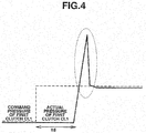
When both of the coast stop control and the above-described low return control are used together, the engine is stopped before the vehicle is stopped due to the coast stop control. Thus, during the vehicle stop, the continuously variable transmission is in a state in which the gear shift ratio is kept at the gear shift ratio higher than the lowest gear shift ratio. If the low return control is executed in this state, there is often a case where the engine needs to be restarted in order to secure a hydraulic pressure required for the low return control. There is a possibility of an overload applied onto a clutch when the engine is started during the low return control. - It is necessary to make a line pressure high in the low return control. When the engine is started to actuate the clutch in a high line pressure, a clutch actual pressure (denoted by a solid line in
Fig. 4 ) with respect to a command pressure (denoted by a broken line inFig. 4 ) generates a hydraulic pressure surge shown in an eclipse broken line after a dead time td. Consequently, the overload is applied to a damper of the clutch. - With the above-described problem in mind, it is an object of the present invention to provide a control apparatus for a hybrid vehicle which can prevent an action of an overload applied to the clutch so as to deteriorate the clutch in a case where the coast stop control of the engine and the low return control are used together.
- Patent document 1: A Japanese Patent Application First Publication (tokkai) No. Heisei
8-312741 - To achieve the above-described object, there is provided a control apparatus for a hybrid vehicle, the hybrid vehicle including an engine, a motor, a continuously variable transmission, a first clutch disposed between the engine and the motor, a second clutch disposed between the motor and the continuously variable transmission, and control means for controlling these, the control means includes: coast stop control means for stopping a fuel supply to the engine when the vehicle is traveling, an accelerator pedal is not depressed, a brake pedal is depressed, and a select position of the continuously variable transmission is in a traveling position; and low return control means for returning a gear ratio of the continuously variable transmission to a low side after the engine is restarted, in a case where the transmission gear ratio of the continuously variable transmission is a midway gear ratio which is higher than a predetermined gear ratio, when detecting that the coast stop control means is operated and the vehicle is stopped.
- In the control apparatus for the hybrid vehicle according to the present invention, the transmission gear ratio is shifted toward the low side after the engine is restarted even if the gear (shift) ratio of the continuously variable transmission is placed at a high gear side, when the fuel supply to the engine is stopped according to the coast stop function. Thus, the deterioration of the clutch due to the action of the overload onto the clutch can be prevented.
-
-
Fig. 1 is a diagrammatical view of a structure of a drive train of a hybrid vehicle in which a control apparatus of a first preferred embodiment according to the present invention and a continuously variable transmission are mounted. -
Fig. 2 is a block diagram representing a structure of the control apparatus in the first preferred embodiment. -
Fig. 3 is a timing chart for explaining an action of the control apparatus in the first preferred embodiment. -
Fig. 4 is a view representing a time variation of a clutch hydraulic pressure for explaining a problem in a conventional control apparatus. - Preferred embodiments according to the present invention will be described in details on a basis of a first preferred embodiment shown in the drawings.
-
Fig. 1 shows a whole structure of a drive train of a hybrid vehicle in which a control apparatus in the first embodiment is mounted. The hybrid vehicle includes: an engine E; a motor M; an oil pump P; a first clutch CL1; a second clutch CL2; and a belt type continuously variable transmission (CVT) 1. The hybrid vehicle can selectively be travelled in an electric automotive vehicle mode (EV mode) in which the vehicle is driven according to an operation of motor M only and in a hybrid vehicle mode (HEV mode) in which the vehicle is driven according to both operations of engine E and motor M. - It should be noted that this hybrid vehicle is a series type hybrid vehicle. The HEV mode includes a mode in which engine E drives motor M, this motor M generates an electric power as a generator, and the vehicle is traveled while motor M charges a battery (not shown) and a mode in which a synthesized force between an output of engine E and the output of motor M due to an electric power supply from the battery drives the vehicle. These modes are selected in accordance with a traveling state and an electrical charge rate of the battery. As an example of these modes, a Japanese Patent Application First Publication No.
2012-206663 - Engine E is an internal combustion engine such as a gasoline engine in which fuel such as gasoline is combusted to output a driving force. Engine E is started, is operated, and is stopped through a control of a fuel supply quantity by
engine controller 2. - Motor M is, for example, constituted by a three-phase alternating current motor. When an electric power from the battery is supplied via an inverter (not shown), the output of motor M can drive continuously
variable transmission 1 and oil pump P. On the other hand, during a vehicle braking, motor M functions as a generator. A part of the braking energy is converted into an electrical energy. The inverter can convert its three phase alternating current into a dc current to charge the battery. In addition, as described above, it is possible for motor M to generate the electric power as a generator by driving motor M via engine E to charge the battery. Motor M is controlled by means of amotor controller 3 via the inverter. - Oil pump P is, for example, a vane type oil pump and is drivable by motor M via a
chain 4 bridged over a sprocket installed on an input axle of oil pump P and a sprocket installed on an output axle of motor M. This oil pump P sucks oil within an oil pan of continuouslyvariable transmission 1 and supplies the discharged oil to a hydraulicpressure control apparatus 1d of continuouslyvariable transmission 1. The hydraulicpressure control apparatus 1d supplies regulated hydraulic pressure to an oil chamber of a primary pulley and performs a gear change and performs a lubrication and cool as an oil lubricating oil to movable parts of mechanical parts. - First clutch CL1 is a multiple plate type clutch and can be connected, disconnected, and slipped between engine E and motor M. This first clutch C1 is released in the EV mode and is clutched or slipped in the HEV mode.
- Second clutch CL2 is another multiple plate type clutch and can be connected, disconnected, and slipped among motor M, oil pump P, and the input axle of continuously
variable transmission 1. This second clutch CL2 is engaged in the EV mode and is slipped in an engaged state in the HEV mode in a case where first clutch CL1 is engaged so that an output of engine E and an output of motor M are synthesized to start the vehicle in a high load such as an abrupt start. In a case where the driving force in a re-acceleration is required, second clutch CL2 is completely engaged state. It should be noted that the control of first clutch CL1 and the control of second clutch CL2 are carried out by atransmission controller 5 in this embodiment. - Continuously
variable transmission 1 is a well known transmission in which ametallic belt 1a is bridged between aprimary pulley 1a linked to the input axle and asecondary pulley 1b linked to the output axle and a groove width between bothpulleys pressure control apparatus 1d to enable to perform a continuously variable transmission. Hence, the detailed structure of continuouslyvariable transmission 1 will, herein, be omitted. Continuouslyvariable transmission 1 is executable a gear shift control carried out along a shift line determined according to an engine revolution number and a vehicle speed throughtransmission controller 5 and a coast stop control, a low return control, and so forth, as will be described later. -
Engine controller 2,motor controller 3, andtransmission controller 5 are controlled by means of an integratedcontroller 6. The low return control bytransmission controller 5 related to the present invention will be described below on a basis ofFig. 2 from among thesecontrollers - As shown in
Fig. 2 ,transmission controller 5 is provided with a low return control section 50 (corresponds to low return control means according to the present invention). When the vehicle is stopped after a fuel supply to engine E, during the deceleration of the vehicle, is stopped, the low return control to return a transmission gear ratio (or transmission speed ratio) to a lowest side in a case where the transmission gear ratio of continuouslyvariable transmission 1 remains at a transmission gear ratio (called as RATIOT) higher than the lowest side (lowest transmission gear ratio) is carried out. This lowreturn control section 50 includes a low return control start determiningsection 51, a lowreturn processing section 52, and anend determining section 53. - Low return control start determining
section 51 determines whether the low return control is executed or not. This low return control start determination is carried out in the following way. That is to say, when the condition as will be described later is established, low return control start determiningsection 51 detects that a coast stop control in which the fuel supply to engine E is stopped is carried out by a coast stop control section 60 (corresponds to coast stop control means according to the present invention) ofintegrated controller 6 and, thereafter, detects that the vehicle is stopped, a low return control start signal is inputted to lowreturn processing section 52. - The condition of executing the coast stop control is that a select lever of continuously
variable transmission 1 is operated in a traveling position, a brake pedal is depressed, an accelerator pedal is released, an oil temperature of continuouslyvariable transmission 1 is within a predetermined range, and the vehicle speed is equal to or below a predetermined vehicle speed. - Low
return processing section 52 allows the low return control upon receipt of the low return start signal from low return control start determiningsection 51, carries out an idle up with engine E started, and does not alter the transmission gear ratio during this period. Subsequently, during the next low return control interval of time, the hydraulic pressure of a hydraulic pressure chamber ofprimary pulley 1a is lowered and the hydraulic pressure ofsecondary pulley 1b is raised. This causes the belt to be longitudinally slipped from the primary pulley side to the secondary pulley side (at this time, since the pulley is not rotated, this is different from the shift during the traveling) so that the gear (shift) ratio is modified to the low side and the gear ratio is finally changed to the lowest position). - Hence, low
return processing section 52 outputs respective command signals such as the start of engine E and idle up of engine E, and a limitation of the engine revolution numbers tointegrated controller 6. In addition, signals of inhibiting the modification of the primary pulley pressure and the modification of the secondary pulley pressure are inputted from lowreturn processing section 52 to hydraulicpressure control apparatus 1d. - Furthermore, at a time point at which a predetermined wait time is passed from a time of the input of the low return start signal, low
return processing section 52 outputs signals of command pressure to the primary pulley and the command pressure to the secondary pulley to hydraulicpressure control apparatus 1d. Hydraulicpressure control apparatus 1d controls these. Lowreturn processing section 52, at the same time, starts a time count at a normal end timer. - After the count time of the normal end timer passes a first predetermined time ts (refer to
Fig. 3 ), a forceful end timer starts the count of time. It should be noted that first predetermined time ts is determined in accordance with a midway gear ratio RATIOT and is set to be longer as midway gear ratio RATIOT becomes a higher side.End determining section 53 determines whether the count time of the normal end timer passes first predetermined time ts. If first predetermined time ts has passed, an end signal is outputted to lowreturn processing section 52 to stop the low return control from lowreturn processing section 52. In addition, when the count time of the forceful end timer is determined to be passed through a second predetermined time tf, the output to the low return control from the lowreturn processing section 52 is forcefully stopped to return to a target signal before the low return control. It should be noted that, in a case where the timer count does not reach to the first and second predetermined times, the above-described outputs are continued form the lowreturn processing section 52. - In a case where
end determining section 53, further, detects that the operation of the select lever by the driver is other than the traveling position, the output for the low return control from lowreturn processing section 52 is forcefully stopped. In addition, a revolution speed ofprimary pulley 1a is monitored on a basis of pulses and, in a case where a peripheral direction slip is detected, the low return control is immediately suspended. - Next, an action of the control apparatus for the hybrid vehicle in this embodiment will be described below with reference to a timing chart of
Fig. 3 .
Variations in time of the vehicle speed, the gear (shift) ratio, the idle up request, the revolution of motor M, the engine revolution speed of engine E, the torque down, the second clutch target torque capacity, the second clutch hydraulic pressure, the secondary (side) pulley pressure, and primary pulley (side) pressure are depicted inFig. 3 sequentially from the upper to the lower. - First, during a time before a time t1, it is a case where the above-described condition for the coast stop is satisfied. During this time, coast
stop control section 60 stops the fuel supply to engine E. Since the brake pedal is depressed, an abrupt decrease in the vehicle speed occurs with the passage of time. During this time, the transmission gear ratio of continuouslyvariable transmission 1 is directed toward a low direction so as to become a lowest position before the vehicle is stopped. As is different from a target gear (shift) ratio (denoted in the solid line) directed to move toward the low direction, an actual gear (shift) ratio (denoted in a broken line) does not return toward the lowest position during the stop of the vehicle (time t1) and stops at midway gear (shift) ratio RATIOT. - When the vehicle stop under the coast stop control is detected by low return control start determining
section 51, the low return control start signal is inputted to lowreturn processing section 52. Lowreturn processing section 52 inputs a signal to modify the target shift ratio (denoted in a dot-and-dash line) to maintain midway gear shift ratio RATIOT stopped in the midway through the stop from the gear shift ratio which provides the lowest position for the target shift ratio to hydraulicpressure control apparatus 1d immediately at time t1 at which the vehicle stop is detected. In addition, the modification inhibit signals (denoted in the solid line) of primary pulley (side) hydraulic pressure and secondary pulley (side) hydraulic pressure are outputted to suppress the modification of the groove width ofpulleys variable transmission 1. Hence, continuouslyvariable transmission 1 maintains the midway gear (shift) ratio RATIOT stopped during the vehicle stop. - Low
return processing section 52 inputs a signal of restarting engine E with second clutch CL2 controlled in the slip state and an idle up signal (its target value is denoted in the dot-and-dash line) tointegrated controller 6. Thus,Engine controller 2 performs a re-start of engine E and an idle up (denoted by the dot-and-dash line). In addition, a revolution limit signal is also inputted from lowreturn processing section 52 tointegrated controller 6 so that the revolution speed of engine E is not reduced below a lower limit value. Furthermore, an EV mode inhibit request signal is inputted not to stop engine E. In addition, a revolution request signal of motor M is inputted tointegrated controller 6 Thus,motor controller 3 raises motor M up to the revolution speed at which oil pump P can secure a required oil quantity. The interval of time from time t1 to time t2 is a low return control allowance interval of time and is a preparation interval of time for the low return control. - At a time t2 at which the wait time has passed, the low return control is executed.
In this state, the speed of motor M can be increased due to the slip control of second clutch CL2 and oil pump P is speed increase driven so as to provide a required hydraulic pressure for the modification of the groove width of the pulleys. At time point t2, a secondary pulley hydraulic pressure rise signal (denoted in the solid line) and a primary pulley drop signal are inputted to hydraulicpressure control apparatus 1d. Consequently, the actual pressure ofsecondary pulley 1b (denoted in the dot-and-dash line) is raised and the actual pressure ofprimary pulley 1a (denoted in the dot-and-dash line) is decreased. These pulleys are not revolved. Hence, the belt is longitudinally slipped due to the variation of the hydraulic pressure so that the actual gear (shift) ratio (denoted in a broken line) gradually approaches to a low side and soon becomes the lowest ratio. - In addition, at a time point of time t2, the timer count is started by means of the normal end timer. When the time has reached to time point t3 at which the timer count reaches to first predetermined time ts, the target gear (shift) ratio is modified to the lowest (transmission gear) ratio from midway (gear shift) ratio RATIOT. As a result of return of the revolution of motor M and idle up to the original state, the actual revolution speed is reduced and becomes constant.
- As appreciated from the above-described explanation, the control apparatus for the hybrid vehicle in the first embodiment has the following effects. That is to say, when detecting that the vehicle stop due to the fuel supply stop to engine E by the coast stop, the transmission gear ratio of continuously
variable transmission 1 is stopped at a midway transmission gear ratio which is higher than a lowest transmission gear ratio position. In this case, second clutch CL2 is made in the slip state, engine E is restarted, and, thereafter, the midway transmission gear ratio of continuouslyvariable transmission 1 is returned to the low side (the lowest transmission gear position is desirable). Thus, it can be prevented that an overload is acted on the clutch so that the clutch is deteriorated. - In other words, since engine E is previously started before the execution of the control (low return control) such that the transmission gear ratio of continuously
variable transmission 1 is returned to the low side, it is not necessary to restart engine E during the execution of the low return control. Thus, even if the required hydraulic pressure in order for the transmission gear ratio to return to the low side during the low return control is not obtained by the driving force of only motor M, engine E is started when the line pressure is in a high state in order for the transmission gear ratio to be returned to the lower side and it is necessary to engage first clutch CL1 in order for the driving force of engine E to be transmitted to oil pump P. Hence, the actual pressure supplied to first clutch CL1 becomes high due to the restart of engine E and due to the operation of first clutch CL1 and the overload applied onto first clutch CL1 can be prevented from occurring. - In addition, the control such that the transmission gear ratio of continuously
variable transmission 1 is returned to the low side is ended at an interval of time from a time at which the coaststop control section 60 is detected to be operated and the vehicle is detected to be stopped to a time at which first predetermined time ts is elapsed, the first predetermined time being set in accordance with the midway transmission gear ratio. Thus, the time required for the low return control can appropriately be set. - In addition, low
return control section 50 suspends the low return control when the select lever position of continuouslyvariable transmission 1 is operated to the other position than the traveling position during the execution of the low return control or when the peripheral direction slip of the primary pulley of continuouslyvariable transmission 1 is detected. Thus, the low return control is not carried out in a case where it is not necessary to execute the low return control after the vehicle stop. - As described above, the present invention has been explained on a basis of the above-described preferred embodiment. The present invention is not limited to each of these embodiments. The present invention includes even if the design modifications are made within a range not deviated from the gist of the present invention.
- For example, in the low return control, a final transmission gear ratio is not the lowest transmission gear ratio but a predetermined transmission gear ratio at a slightly higher side than the lowest transmission gear ratio.
- In addition, a role-sharing of each kind of
controllers
Claims (4)
- A control apparatus for a hybrid vehicle, the hybrid vehicle having: an engine in which fuel is combusted to enable an output of a driving force; a motor which is enabled to output the driving force by means of an electric power; a continuously variable transmission which is enabled to perform a continuously variable transmission between an input and an output; a first clutch disposed between the engine and the motor; a second clutch disposed between the motor and the continuously variable transmission; and control means for controlling the engine, the motor, the continuously variable transmission, the first clutch, and the second clutch, the control means comprising:coast stop control means for stopping a fuel supply to the engine when the vehicle is traveling, an accelerator pedal is not depressed, a brake pedal is depressed, and a select position of the continuously variable transmission is in a traveling position; andlow return control means for returning a transmission gear ratio of the continuously variable transmission to a low side after the second clutch is released and the engine is restarted in a case where the transmission gear ratio of the continuously variable transmission is a midway transmission gear ratio which is higher than a predetermined transmission gear ratio, when the coast stop control means is operated and the vehicle is detected to be stopped.
- The control apparatus for the hybrid vehicle as claimed in claim 1, wherein the predetermined transmission gear ratio is a lowest transmission gear ratio.
- The control apparatus for the hybrid vehicle as claimed in either claim 1 or 2, wherein the control of returning the transmission gear ratio of the continuously variable transmission to the lower side is ended for an interval of time from a time at which the coast stop control means is operated and the vehicle is detected to be stopped to a time at which a first predetermined time has elapsed, the first predetermined time being set in accordance with the midway transmission gear ratio.
- The control apparatus for the hybrid vehicle as claimed in any one of the preceding claims 1 through 3, wherein the low return control means suspends the low return control when the select position of the continuously variable transmission is operated at a position other than the traveling position during an execution of the low return control or when a peripheral directional slip of a primary pulley of the continuously variable transmission is detected.
Applications Claiming Priority (2)
| Application Number | Priority Date | Filing Date | Title |
|---|---|---|---|
| JP2013191097 | 2013-09-13 | ||
| PCT/JP2014/073276 WO2015037502A1 (en) | 2013-09-13 | 2014-09-04 | Hybrid vehicle control device |
Publications (3)
| Publication Number | Publication Date |
|---|---|
| EP3045362A1 true EP3045362A1 (en) | 2016-07-20 |
| EP3045362A4 EP3045362A4 (en) | 2017-01-18 |
| EP3045362B1 EP3045362B1 (en) | 2020-01-22 |
Family
ID=52665608
Family Applications (1)
| Application Number | Title | Priority Date | Filing Date |
|---|---|---|---|
| EP14843247.9A Active EP3045362B1 (en) | 2013-09-13 | 2014-09-04 | Control apparatus for a hybrid vehicle |
Country Status (6)
| Country | Link |
|---|---|
| US (1) | US9616882B2 (en) |
| EP (1) | EP3045362B1 (en) |
| JP (1) | JP5980435B2 (en) |
| KR (1) | KR101697909B1 (en) |
| CN (1) | CN105517869B (en) |
| WO (1) | WO2015037502A1 (en) |
Cited By (1)
| Publication number | Priority date | Publication date | Assignee | Title |
|---|---|---|---|---|
| US10672207B2 (en) | 2017-01-20 | 2020-06-02 | Polaris Industries Inc. | Diagnostic systems and methods of a continuously variable transmission |
Families Citing this family (8)
| Publication number | Priority date | Publication date | Assignee | Title |
|---|---|---|---|---|
| KR101697909B1 (en) * | 2013-09-13 | 2017-01-18 | 쟈트코 가부시키가이샤 | Hybrid vehicle control device |
| JP6420653B2 (en) * | 2014-12-11 | 2018-11-07 | 株式会社エフ・シー・シー | Power transmission device for hybrid vehicle |
| JP6510948B2 (en) * | 2015-10-02 | 2019-05-08 | ジヤトコ株式会社 | Vehicle control device |
| NL1041928B1 (en) * | 2016-06-14 | 2017-12-21 | Bosch Gmbh Robert | Method for operating a continuously variable transmission in a motor vehicle equipped therewith |
| JP6614597B2 (en) * | 2016-07-01 | 2019-12-11 | ジヤトコ株式会社 | Control device for hybrid vehicle |
| CN107605607B (en) * | 2017-09-15 | 2019-08-02 | 北理慧动(常熟)车辆科技有限公司 | Engine control and device |
| JP7319893B2 (en) * | 2019-11-06 | 2023-08-02 | 株式会社Subaru | vehicle controller |
| JP7729185B2 (en) * | 2021-11-10 | 2025-08-26 | トヨタ自動車株式会社 | Hybrid vehicle control device |
Family Cites Families (26)
| Publication number | Priority date | Publication date | Assignee | Title |
|---|---|---|---|---|
| JP3369594B2 (en) | 1992-05-29 | 2003-01-20 | 本田技研工業株式会社 | Electric traveling car |
| JPH08312741A (en) | 1995-05-15 | 1996-11-26 | Nissan Motor Co Ltd | Controller for continuously variable automatic transmission |
| JPH0914416A (en) * | 1995-06-28 | 1997-01-14 | Suzuki Motor Corp | Transmission control device for continuously variable transmission |
| JP2000023313A (en) * | 1998-07-06 | 2000-01-21 | Suzuki Motor Corp | Drive unit for hybrid vehicles |
| JP3691296B2 (en) | 1999-08-02 | 2005-09-07 | 本田技研工業株式会社 | Engine control device |
| JP2001088585A (en) * | 1999-09-24 | 2001-04-03 | Mitsubishi Motors Corp | Hybrid vehicle control device |
| DE60136987D1 (en) * | 2000-01-17 | 2009-01-29 | Honda Motor Co Ltd | Hybrid vehicle with a control device |
| JP3550068B2 (en) * | 2000-01-24 | 2004-08-04 | 本田技研工業株式会社 | Hybrid vehicle control device |
| JP3610962B2 (en) * | 2002-04-09 | 2005-01-19 | トヨタ自動車株式会社 | Control device for vehicle braking force |
| JP4191968B2 (en) * | 2002-08-27 | 2008-12-03 | トヨタ自動車株式会社 | Vehicle drive control device |
| JP5602687B2 (en) * | 2004-07-02 | 2014-10-08 | ヤマハ発動機株式会社 | vehicle |
| JP4270459B2 (en) * | 2004-08-09 | 2009-06-03 | 本田技研工業株式会社 | Control device for continuously variable transmission mechanism |
| JP4627425B2 (en) * | 2004-09-29 | 2011-02-09 | 本田技研工業株式会社 | Shift control device for continuously variable transmission |
| JP2006170265A (en) | 2004-12-14 | 2006-06-29 | Toyota Motor Corp | Automobile and control method thereof |
| JP2006234043A (en) * | 2005-02-24 | 2006-09-07 | Fujitsu Ten Ltd | VEHICLE CONTROL DEVICE AND ITS CONTROL METHOD |
| JP5076516B2 (en) | 2007-01-24 | 2012-11-21 | 日産自動車株式会社 | Mode change control device for shifting of hybrid vehicle |
| JP2009264475A (en) | 2008-04-24 | 2009-11-12 | Toyota Motor Corp | Control device for vehicular continuously variable transmission |
| JP5476732B2 (en) | 2009-02-16 | 2014-04-23 | 日産自動車株式会社 | Vehicle shift control device and shift control method |
| JP5039098B2 (en) * | 2009-07-24 | 2012-10-03 | 日産自動車株式会社 | Control device for hybrid vehicle |
| US8574125B2 (en) * | 2010-12-30 | 2013-11-05 | Ford Global Technologies, Llc | Methods and systems for assisted direct start control |
| JP5474857B2 (en) | 2011-03-23 | 2014-04-16 | ジヤトコ株式会社 | Control device for continuously variable transmission |
| JP2012206663A (en) | 2011-03-30 | 2012-10-25 | Jatco Ltd | Speed change control device of hybrid vehicle |
| JP2013086649A (en) | 2011-10-18 | 2013-05-13 | Jatco Ltd | Controller for hybrid vehicle |
| JP2012076740A (en) | 2011-11-15 | 2012-04-19 | Nissan Motor Co Ltd | Hybrid vehicle control device |
| CN103717862B (en) * | 2012-07-16 | 2015-04-29 | 本田技研工业株式会社 | Vehicle control device |
| KR101697909B1 (en) * | 2013-09-13 | 2017-01-18 | 쟈트코 가부시키가이샤 | Hybrid vehicle control device |
-
2014
- 2014-09-04 KR KR1020167004027A patent/KR101697909B1/en not_active Expired - Fee Related
- 2014-09-04 CN CN201480048380.4A patent/CN105517869B/en active Active
- 2014-09-04 US US14/913,591 patent/US9616882B2/en active Active
- 2014-09-04 EP EP14843247.9A patent/EP3045362B1/en active Active
- 2014-09-04 WO PCT/JP2014/073276 patent/WO2015037502A1/en not_active Ceased
- 2014-09-04 JP JP2015536546A patent/JP5980435B2/en active Active
Cited By (3)
| Publication number | Priority date | Publication date | Assignee | Title |
|---|---|---|---|---|
| US10672207B2 (en) | 2017-01-20 | 2020-06-02 | Polaris Industries Inc. | Diagnostic systems and methods of a continuously variable transmission |
| US11430272B2 (en) | 2017-01-20 | 2022-08-30 | Polaris Industries Inc. | Diagnostic systems and methods of a continuously variable transmission |
| US12118835B2 (en) | 2017-01-20 | 2024-10-15 | Polaris Industries Inc. | Diagnostic systems and methods of a continuously variable transmission |
Also Published As
| Publication number | Publication date |
|---|---|
| KR20160033175A (en) | 2016-03-25 |
| EP3045362B1 (en) | 2020-01-22 |
| KR101697909B1 (en) | 2017-01-18 |
| US9616882B2 (en) | 2017-04-11 |
| JPWO2015037502A1 (en) | 2017-03-02 |
| CN105517869A (en) | 2016-04-20 |
| WO2015037502A1 (en) | 2015-03-19 |
| JP5980435B2 (en) | 2016-08-31 |
| US20160207524A1 (en) | 2016-07-21 |
| CN105517869B (en) | 2018-03-16 |
| EP3045362A4 (en) | 2017-01-18 |
Similar Documents
| Publication | Publication Date | Title |
|---|---|---|
| US9616882B2 (en) | Hybrid vehicle control device | |
| US10173683B2 (en) | Vehicle control device and vehicle control method | |
| JP5888429B2 (en) | Start control device for hybrid vehicle | |
| US9234579B2 (en) | Control device and control method for vehicular electric oil pump | |
| US9561793B2 (en) | Driving apparatus for hybrid vehicle and control method thereof | |
| JP5896734B2 (en) | Control device for hybrid vehicle | |
| KR102105888B1 (en) | Hybrid vehicle control unit | |
| US10071737B2 (en) | Vehicle control apparatus | |
| WO2014013901A1 (en) | Vehicle control device | |
| US10240672B2 (en) | Control device for continuously variable transmission and method for controlling the same | |
| US11383697B2 (en) | Vehicle control apparatus | |
| JP5945628B2 (en) | Hybrid vehicle failure determination device and failure determination method thereof | |
| US10086817B2 (en) | Control device and control method for vehicle | |
| JP2012220010A (en) | Vehicular control device | |
| JP2017171063A (en) | Vehicle control device | |
| JP5589944B2 (en) | Vehicle control device |
Legal Events
| Date | Code | Title | Description |
|---|---|---|---|
| PUAI | Public reference made under article 153(3) epc to a published international application that has entered the european phase |
Free format text: ORIGINAL CODE: 0009012 |
|
| 17P | Request for examination filed |
Effective date: 20160303 |
|
| AK | Designated contracting states |
Kind code of ref document: A1 Designated state(s): AL AT BE BG CH CY CZ DE DK EE ES FI FR GB GR HR HU IE IS IT LI LT LU LV MC MK MT NL NO PL PT RO RS SE SI SK SM TR |
|
| AX | Request for extension of the european patent |
Extension state: BA ME |
|
| DAX | Request for extension of the european patent (deleted) | ||
| A4 | Supplementary search report drawn up and despatched |
Effective date: 20161219 |
|
| RIC1 | Information provided on ipc code assigned before grant |
Ipc: B60W 10/08 20060101ALI20161213BHEP Ipc: B60K 6/48 20071001ALI20161213BHEP Ipc: B60W 10/10 20120101AFI20161213BHEP Ipc: F16H 61/02 20060101ALI20161213BHEP Ipc: B60W 20/40 20160101ALI20161213BHEP Ipc: B60W 10/02 20060101ALI20161213BHEP Ipc: B60K 6/543 20071001ALI20161213BHEP Ipc: B60W 10/06 20060101ALI20161213BHEP Ipc: B60K 6/387 20071001ALI20161213BHEP Ipc: B60W 30/186 20120101ALI20161213BHEP Ipc: F16H 61/662 20060101ALI20161213BHEP Ipc: B60W 10/30 20060101ALI20161213BHEP Ipc: B60W 20/00 20160101ALI20161213BHEP Ipc: B60W 10/107 20120101ALI20161213BHEP Ipc: B60W 30/18 20120101ALI20161213BHEP |
|
| STAA | Information on the status of an ep patent application or granted ep patent |
Free format text: STATUS: EXAMINATION IS IN PROGRESS |
|
| 17Q | First examination report despatched |
Effective date: 20190403 |
|
| GRAP | Despatch of communication of intention to grant a patent |
Free format text: ORIGINAL CODE: EPIDOSNIGR1 |
|
| STAA | Information on the status of an ep patent application or granted ep patent |
Free format text: STATUS: GRANT OF PATENT IS INTENDED |
|
| INTG | Intention to grant announced |
Effective date: 20190927 |
|
| GRAS | Grant fee paid |
Free format text: ORIGINAL CODE: EPIDOSNIGR3 |
|
| GRAA | (expected) grant |
Free format text: ORIGINAL CODE: 0009210 |
|
| STAA | Information on the status of an ep patent application or granted ep patent |
Free format text: STATUS: THE PATENT HAS BEEN GRANTED |
|
| AK | Designated contracting states |
Kind code of ref document: B1 Designated state(s): AL AT BE BG CH CY CZ DE DK EE ES FI FR GB GR HR HU IE IS IT LI LT LU LV MC MK MT NL NO PL PT RO RS SE SI SK SM TR |
|
| REG | Reference to a national code |
Ref country code: GB Ref legal event code: FG4D |
|
| REG | Reference to a national code |
Ref country code: CH Ref legal event code: EP |
|
| REG | Reference to a national code |
Ref country code: AT Ref legal event code: REF Ref document number: 1226738 Country of ref document: AT Kind code of ref document: T Effective date: 20200215 |
|
| REG | Reference to a national code |
Ref country code: IE Ref legal event code: FG4D |
|
| REG | Reference to a national code |
Ref country code: DE Ref legal event code: R096 Ref document number: 602014060456 Country of ref document: DE |
|
| REG | Reference to a national code |
Ref country code: NL Ref legal event code: MP Effective date: 20200122 |
|
| REG | Reference to a national code |
Ref country code: LT Ref legal event code: MG4D |
|
| PG25 | Lapsed in a contracting state [announced via postgrant information from national office to epo] |
Ref country code: NL Free format text: LAPSE BECAUSE OF FAILURE TO SUBMIT A TRANSLATION OF THE DESCRIPTION OR TO PAY THE FEE WITHIN THE PRESCRIBED TIME-LIMIT Effective date: 20200122 Ref country code: PT Free format text: LAPSE BECAUSE OF FAILURE TO SUBMIT A TRANSLATION OF THE DESCRIPTION OR TO PAY THE FEE WITHIN THE PRESCRIBED TIME-LIMIT Effective date: 20200614 Ref country code: NO Free format text: LAPSE BECAUSE OF FAILURE TO SUBMIT A TRANSLATION OF THE DESCRIPTION OR TO PAY THE FEE WITHIN THE PRESCRIBED TIME-LIMIT Effective date: 20200422 Ref country code: FI Free format text: LAPSE BECAUSE OF FAILURE TO SUBMIT A TRANSLATION OF THE DESCRIPTION OR TO PAY THE FEE WITHIN THE PRESCRIBED TIME-LIMIT Effective date: 20200122 Ref country code: RS Free format text: LAPSE BECAUSE OF FAILURE TO SUBMIT A TRANSLATION OF THE DESCRIPTION OR TO PAY THE FEE WITHIN THE PRESCRIBED TIME-LIMIT Effective date: 20200122 |
|
| PG25 | Lapsed in a contracting state [announced via postgrant information from national office to epo] |
Ref country code: LV Free format text: LAPSE BECAUSE OF FAILURE TO SUBMIT A TRANSLATION OF THE DESCRIPTION OR TO PAY THE FEE WITHIN THE PRESCRIBED TIME-LIMIT Effective date: 20200122 Ref country code: SE Free format text: LAPSE BECAUSE OF FAILURE TO SUBMIT A TRANSLATION OF THE DESCRIPTION OR TO PAY THE FEE WITHIN THE PRESCRIBED TIME-LIMIT Effective date: 20200122 Ref country code: HR Free format text: LAPSE BECAUSE OF FAILURE TO SUBMIT A TRANSLATION OF THE DESCRIPTION OR TO PAY THE FEE WITHIN THE PRESCRIBED TIME-LIMIT Effective date: 20200122 Ref country code: GR Free format text: LAPSE BECAUSE OF FAILURE TO SUBMIT A TRANSLATION OF THE DESCRIPTION OR TO PAY THE FEE WITHIN THE PRESCRIBED TIME-LIMIT Effective date: 20200423 Ref country code: IS Free format text: LAPSE BECAUSE OF FAILURE TO SUBMIT A TRANSLATION OF THE DESCRIPTION OR TO PAY THE FEE WITHIN THE PRESCRIBED TIME-LIMIT Effective date: 20200522 Ref country code: BG Free format text: LAPSE BECAUSE OF FAILURE TO SUBMIT A TRANSLATION OF THE DESCRIPTION OR TO PAY THE FEE WITHIN THE PRESCRIBED TIME-LIMIT Effective date: 20200422 |
|
| REG | Reference to a national code |
Ref country code: DE Ref legal event code: R097 Ref document number: 602014060456 Country of ref document: DE |
|
| PG25 | Lapsed in a contracting state [announced via postgrant information from national office to epo] |
Ref country code: SK Free format text: LAPSE BECAUSE OF FAILURE TO SUBMIT A TRANSLATION OF THE DESCRIPTION OR TO PAY THE FEE WITHIN THE PRESCRIBED TIME-LIMIT Effective date: 20200122 Ref country code: LT Free format text: LAPSE BECAUSE OF FAILURE TO SUBMIT A TRANSLATION OF THE DESCRIPTION OR TO PAY THE FEE WITHIN THE PRESCRIBED TIME-LIMIT Effective date: 20200122 Ref country code: EE Free format text: LAPSE BECAUSE OF FAILURE TO SUBMIT A TRANSLATION OF THE DESCRIPTION OR TO PAY THE FEE WITHIN THE PRESCRIBED TIME-LIMIT Effective date: 20200122 Ref country code: SM Free format text: LAPSE BECAUSE OF FAILURE TO SUBMIT A TRANSLATION OF THE DESCRIPTION OR TO PAY THE FEE WITHIN THE PRESCRIBED TIME-LIMIT Effective date: 20200122 Ref country code: CZ Free format text: LAPSE BECAUSE OF FAILURE TO SUBMIT A TRANSLATION OF THE DESCRIPTION OR TO PAY THE FEE WITHIN THE PRESCRIBED TIME-LIMIT Effective date: 20200122 Ref country code: RO Free format text: LAPSE BECAUSE OF FAILURE TO SUBMIT A TRANSLATION OF THE DESCRIPTION OR TO PAY THE FEE WITHIN THE PRESCRIBED TIME-LIMIT Effective date: 20200122 Ref country code: ES Free format text: LAPSE BECAUSE OF FAILURE TO SUBMIT A TRANSLATION OF THE DESCRIPTION OR TO PAY THE FEE WITHIN THE PRESCRIBED TIME-LIMIT Effective date: 20200122 Ref country code: DK Free format text: LAPSE BECAUSE OF FAILURE TO SUBMIT A TRANSLATION OF THE DESCRIPTION OR TO PAY THE FEE WITHIN THE PRESCRIBED TIME-LIMIT Effective date: 20200122 |
|
| REG | Reference to a national code |
Ref country code: AT Ref legal event code: MK05 Ref document number: 1226738 Country of ref document: AT Kind code of ref document: T Effective date: 20200122 |
|
| PLBE | No opposition filed within time limit |
Free format text: ORIGINAL CODE: 0009261 |
|
| STAA | Information on the status of an ep patent application or granted ep patent |
Free format text: STATUS: NO OPPOSITION FILED WITHIN TIME LIMIT |
|
| 26N | No opposition filed |
Effective date: 20201023 |
|
| PG25 | Lapsed in a contracting state [announced via postgrant information from national office to epo] |
Ref country code: AT Free format text: LAPSE BECAUSE OF FAILURE TO SUBMIT A TRANSLATION OF THE DESCRIPTION OR TO PAY THE FEE WITHIN THE PRESCRIBED TIME-LIMIT Effective date: 20200122 Ref country code: IT Free format text: LAPSE BECAUSE OF FAILURE TO SUBMIT A TRANSLATION OF THE DESCRIPTION OR TO PAY THE FEE WITHIN THE PRESCRIBED TIME-LIMIT Effective date: 20200122 |
|
| PG25 | Lapsed in a contracting state [announced via postgrant information from national office to epo] |
Ref country code: PL Free format text: LAPSE BECAUSE OF FAILURE TO SUBMIT A TRANSLATION OF THE DESCRIPTION OR TO PAY THE FEE WITHIN THE PRESCRIBED TIME-LIMIT Effective date: 20200122 Ref country code: SI Free format text: LAPSE BECAUSE OF FAILURE TO SUBMIT A TRANSLATION OF THE DESCRIPTION OR TO PAY THE FEE WITHIN THE PRESCRIBED TIME-LIMIT Effective date: 20200122 |
|
| PG25 | Lapsed in a contracting state [announced via postgrant information from national office to epo] |
Ref country code: MC Free format text: LAPSE BECAUSE OF FAILURE TO SUBMIT A TRANSLATION OF THE DESCRIPTION OR TO PAY THE FEE WITHIN THE PRESCRIBED TIME-LIMIT Effective date: 20200122 |
|
| REG | Reference to a national code |
Ref country code: CH Ref legal event code: PL |
|
| GBPC | Gb: european patent ceased through non-payment of renewal fee |
Effective date: 20200904 |
|
| REG | Reference to a national code |
Ref country code: BE Ref legal event code: MM Effective date: 20200930 |
|
| PG25 | Lapsed in a contracting state [announced via postgrant information from national office to epo] |
Ref country code: LU Free format text: LAPSE BECAUSE OF NON-PAYMENT OF DUE FEES Effective date: 20200904 |
|
| PG25 | Lapsed in a contracting state [announced via postgrant information from national office to epo] |
Ref country code: FR Free format text: LAPSE BECAUSE OF NON-PAYMENT OF DUE FEES Effective date: 20200930 |
|
| PG25 | Lapsed in a contracting state [announced via postgrant information from national office to epo] |
Ref country code: LI Free format text: LAPSE BECAUSE OF NON-PAYMENT OF DUE FEES Effective date: 20200930 Ref country code: GB Free format text: LAPSE BECAUSE OF NON-PAYMENT OF DUE FEES Effective date: 20200904 Ref country code: IE Free format text: LAPSE BECAUSE OF NON-PAYMENT OF DUE FEES Effective date: 20200904 Ref country code: CH Free format text: LAPSE BECAUSE OF NON-PAYMENT OF DUE FEES Effective date: 20200930 Ref country code: BE Free format text: LAPSE BECAUSE OF NON-PAYMENT OF DUE FEES Effective date: 20200930 |
|
| PG25 | Lapsed in a contracting state [announced via postgrant information from national office to epo] |
Ref country code: TR Free format text: LAPSE BECAUSE OF FAILURE TO SUBMIT A TRANSLATION OF THE DESCRIPTION OR TO PAY THE FEE WITHIN THE PRESCRIBED TIME-LIMIT Effective date: 20200122 Ref country code: MT Free format text: LAPSE BECAUSE OF FAILURE TO SUBMIT A TRANSLATION OF THE DESCRIPTION OR TO PAY THE FEE WITHIN THE PRESCRIBED TIME-LIMIT Effective date: 20200122 Ref country code: CY Free format text: LAPSE BECAUSE OF FAILURE TO SUBMIT A TRANSLATION OF THE DESCRIPTION OR TO PAY THE FEE WITHIN THE PRESCRIBED TIME-LIMIT Effective date: 20200122 |
|
| PG25 | Lapsed in a contracting state [announced via postgrant information from national office to epo] |
Ref country code: MK Free format text: LAPSE BECAUSE OF FAILURE TO SUBMIT A TRANSLATION OF THE DESCRIPTION OR TO PAY THE FEE WITHIN THE PRESCRIBED TIME-LIMIT Effective date: 20200122 Ref country code: AL Free format text: LAPSE BECAUSE OF FAILURE TO SUBMIT A TRANSLATION OF THE DESCRIPTION OR TO PAY THE FEE WITHIN THE PRESCRIBED TIME-LIMIT Effective date: 20200122 |
|
| PGFP | Annual fee paid to national office [announced via postgrant information from national office to epo] |
Ref country code: DE Payment date: 20250730 Year of fee payment: 12 |