EP3045361A1 - Bi-stable voice coil park brake - Google Patents
Bi-stable voice coil park brake Download PDFInfo
- Publication number
- EP3045361A1 EP3045361A1 EP16151102.7A EP16151102A EP3045361A1 EP 3045361 A1 EP3045361 A1 EP 3045361A1 EP 16151102 A EP16151102 A EP 16151102A EP 3045361 A1 EP3045361 A1 EP 3045361A1
- Authority
- EP
- European Patent Office
- Prior art keywords
- motor shaft
- diameter portion
- bobbin
- way clutch
- disposed
- Prior art date
- Legal status (The legal status is an assumption and is not a legal conclusion. Google has not performed a legal analysis and makes no representation as to the accuracy of the status listed.)
- Granted
Links
- 238000000034 method Methods 0.000 claims abstract description 29
- 230000007246 mechanism Effects 0.000 claims abstract description 23
- 230000004044 response Effects 0.000 claims abstract description 19
- 239000005043 ethylene-methyl acrylate Substances 0.000 claims description 3
- 230000005294 ferromagnetic effect Effects 0.000 claims description 3
- 229910000831 Steel Inorganic materials 0.000 description 9
- 239000010959 steel Substances 0.000 description 9
- 230000008901 benefit Effects 0.000 description 6
- 230000005291 magnetic effect Effects 0.000 description 6
- OKTJSMMVPCPJKN-UHFFFAOYSA-N Carbon Chemical compound [C] OKTJSMMVPCPJKN-UHFFFAOYSA-N 0.000 description 3
- 229910052799 carbon Inorganic materials 0.000 description 3
- 239000003302 ferromagnetic material Substances 0.000 description 3
- 239000000463 material Substances 0.000 description 3
- 230000008569 process Effects 0.000 description 3
- 239000002783 friction material Substances 0.000 description 2
- RYGMFSIKBFXOCR-UHFFFAOYSA-N Copper Chemical compound [Cu] RYGMFSIKBFXOCR-UHFFFAOYSA-N 0.000 description 1
- 230000001133 acceleration Effects 0.000 description 1
- 230000008859 change Effects 0.000 description 1
- 238000004891 communication Methods 0.000 description 1
- 230000006835 compression Effects 0.000 description 1
- 238000007906 compression Methods 0.000 description 1
- 239000004020 conductor Substances 0.000 description 1
- 229910052802 copper Inorganic materials 0.000 description 1
- 239000010949 copper Substances 0.000 description 1
- 230000008878 coupling Effects 0.000 description 1
- 238000010168 coupling process Methods 0.000 description 1
- 238000005859 coupling reaction Methods 0.000 description 1
- 230000004907 flux Effects 0.000 description 1
- 239000011159 matrix material Substances 0.000 description 1
- 238000005096 rolling process Methods 0.000 description 1
- 239000000126 substance Substances 0.000 description 1
Images


Classifications
-
- B—PERFORMING OPERATIONS; TRANSPORTING
- B64—AIRCRAFT; AVIATION; COSMONAUTICS
- B64C—AEROPLANES; HELICOPTERS
- B64C25/00—Alighting gear
- B64C25/32—Alighting gear characterised by elements which contact the ground or similar surface
- B64C25/42—Arrangement or adaptation of brakes
- B64C25/44—Actuating mechanisms
-
- B—PERFORMING OPERATIONS; TRANSPORTING
- B60—VEHICLES IN GENERAL
- B60T—VEHICLE BRAKE CONTROL SYSTEMS OR PARTS THEREOF; BRAKE CONTROL SYSTEMS OR PARTS THEREOF, IN GENERAL; ARRANGEMENT OF BRAKING ELEMENTS ON VEHICLES IN GENERAL; PORTABLE DEVICES FOR PREVENTING UNWANTED MOVEMENT OF VEHICLES; VEHICLE MODIFICATIONS TO FACILITATE COOLING OF BRAKES
- B60T13/00—Transmitting braking action from initiating means to ultimate brake actuator with power assistance or drive; Brake systems incorporating such transmitting means, e.g. air-pressure brake systems
- B60T13/74—Transmitting braking action from initiating means to ultimate brake actuator with power assistance or drive; Brake systems incorporating such transmitting means, e.g. air-pressure brake systems with electrical assistance or drive
- B60T13/741—Transmitting braking action from initiating means to ultimate brake actuator with power assistance or drive; Brake systems incorporating such transmitting means, e.g. air-pressure brake systems with electrical assistance or drive acting on an ultimate actuator
-
- B—PERFORMING OPERATIONS; TRANSPORTING
- B60—VEHICLES IN GENERAL
- B60T—VEHICLE BRAKE CONTROL SYSTEMS OR PARTS THEREOF; BRAKE CONTROL SYSTEMS OR PARTS THEREOF, IN GENERAL; ARRANGEMENT OF BRAKING ELEMENTS ON VEHICLES IN GENERAL; PORTABLE DEVICES FOR PREVENTING UNWANTED MOVEMENT OF VEHICLES; VEHICLE MODIFICATIONS TO FACILITATE COOLING OF BRAKES
- B60T13/00—Transmitting braking action from initiating means to ultimate brake actuator with power assistance or drive; Brake systems incorporating such transmitting means, e.g. air-pressure brake systems
- B60T13/74—Transmitting braking action from initiating means to ultimate brake actuator with power assistance or drive; Brake systems incorporating such transmitting means, e.g. air-pressure brake systems with electrical assistance or drive
- B60T13/748—Transmitting braking action from initiating means to ultimate brake actuator with power assistance or drive; Brake systems incorporating such transmitting means, e.g. air-pressure brake systems with electrical assistance or drive acting on electro-magnetic brakes
-
- F—MECHANICAL ENGINEERING; LIGHTING; HEATING; WEAPONS; BLASTING
- F16—ENGINEERING ELEMENTS AND UNITS; GENERAL MEASURES FOR PRODUCING AND MAINTAINING EFFECTIVE FUNCTIONING OF MACHINES OR INSTALLATIONS; THERMAL INSULATION IN GENERAL
- F16D—COUPLINGS FOR TRANSMITTING ROTATION; CLUTCHES; BRAKES
- F16D49/00—Brakes with a braking member co-operating with the periphery of a drum, wheel-rim, or the like
- F16D49/02—Brakes with a braking member co-operating with the periphery of a drum, wheel-rim, or the like shaped as a helical band or coil with more than one turn, with or without intensification of the braking force by the tension of the band or contracting member
-
- F—MECHANICAL ENGINEERING; LIGHTING; HEATING; WEAPONS; BLASTING
- F16—ENGINEERING ELEMENTS AND UNITS; GENERAL MEASURES FOR PRODUCING AND MAINTAINING EFFECTIVE FUNCTIONING OF MACHINES OR INSTALLATIONS; THERMAL INSULATION IN GENERAL
- F16D—COUPLINGS FOR TRANSMITTING ROTATION; CLUTCHES; BRAKES
- F16D63/00—Brakes not otherwise provided for; Brakes combining more than one of the types of groups F16D49/00 - F16D61/00
- F16D63/002—Brakes with direct electrical or electro-magnetic actuation
-
- F—MECHANICAL ENGINEERING; LIGHTING; HEATING; WEAPONS; BLASTING
- F16—ENGINEERING ELEMENTS AND UNITS; GENERAL MEASURES FOR PRODUCING AND MAINTAINING EFFECTIVE FUNCTIONING OF MACHINES OR INSTALLATIONS; THERMAL INSULATION IN GENERAL
- F16D—COUPLINGS FOR TRANSMITTING ROTATION; CLUTCHES; BRAKES
- F16D65/00—Parts or details
- F16D65/14—Actuating mechanisms for brakes; Means for initiating operation at a predetermined position
- F16D65/16—Actuating mechanisms for brakes; Means for initiating operation at a predetermined position arranged in or on the brake
-
- F—MECHANICAL ENGINEERING; LIGHTING; HEATING; WEAPONS; BLASTING
- F16—ENGINEERING ELEMENTS AND UNITS; GENERAL MEASURES FOR PRODUCING AND MAINTAINING EFFECTIVE FUNCTIONING OF MACHINES OR INSTALLATIONS; THERMAL INSULATION IN GENERAL
- F16D—COUPLINGS FOR TRANSMITTING ROTATION; CLUTCHES; BRAKES
- F16D2127/00—Auxiliary mechanisms
- F16D2127/06—Locking mechanisms, e.g. acting on actuators, on release mechanisms or on force transmission mechanisms
Definitions
- the present disclosure relates to braking systems and methods, and more particularly, to park brake systems and methods.
- Typical aircraft brakes comprise one or more rotors and stators that, when compressed axially, cause an aircraft wheel to resist rotation. While parked, it may be desirable to maintain brake compression to resist unwanted movement of the aircraft.
- a park brake system may comprise a motor shaft having a first diameter portion and a second diameter portion, the second diameter portion having a greater diameter than the first diameter portion, a spring disposed at least partially around a circumference of the motor shaft, a wire coil disposed at least partially around a circumference of a bobbin, a one-way clutch disposed at least partially within the bobbin and coaxial to the motor shaft, an annular magnet disposed coaxial to the motor shaft and distal to at least a portion of the bobbin, and a clutch release mechanism disposed coaxial to the motor shaft and around the first diameter portion.
- the one-way clutch In response to a first voltage applied to the wire coil, the one-way clutch may translate axially in a first direction relative to the motor shaft and engage with the second diameter portion, preventing rotation of the motor shaft in a first rotational direction. In response to a second voltage applied to the wire coil, the one-way clutch may translate axially in a second direction relative to the motor shaft and engage with the clutch release mechanism, thereby allowing rotation of the motor shaft in a first rotational direction.
- the present disclosure provides methods of using a bi-stable voice coil park brake. Such methods may comprise applying a first voltage to a wire coil, translating a one-way clutch axially in a first direction, engaging the one-way clutch with a motor shaft, applying a second voltage to the wire coil, translating the one-way clutch in a second direction, and engaging the one-way clutch with a clutch release mechanism.
- any of the method or process descriptions may be executed in any order and are not necessarily limited to the order presented.
- any reference to singular includes plural embodiments, and any reference to more than one component or step may include a singular embodiment or step.
- any reference to attached, fixed, connected, or the like may include permanent, removable, temporary, partial, full, and/or any other possible attachment option.
- any reference to without contact (or similar phrases) may also include reduced contact or minimal contact.
- An aircraft park brake system may comprise an end plate distal from a plurality of interleaved rotor disks and stator disks which together form a brake heat sink.
- Each rotor disk may be coupled to a wheel for rotation therewith and each stator disk may be coupled to a wheel support, which resists rotation.
- the brake mechanism also generally includes a torque tube and a back leg on which a pressure plate, end plate, and stator disks are slidably mounted against rotation relative to the wheel and rotor disks.
- the stator disks may comprise two wear faces and the pressure plate may comprise a single wear face.
- the rotor disks and stator disks may be formed of a friction material, such as a carbon/carbon or a carbon metallic matrix material.
- a brake head may house the piston motor or one or more rams that extend to move the pressure plate and axially compress the brake disk stack against the end plate.
- a brake system may comprise a brake system controller ("BSC") coupled to one or more electromechanical actuator controllers (“EMACs”), each of which may drive an electromechanical actuator (“EMA”).
- BSC brake system controller
- EMACs electromechanical actuator controllers
- the BSC may be in communication with a brake pedal, and thus may control the EMACs in accordance with pilot/copilot braking commands.
- the EMA may be coupled to or otherwise operate a pressure generating device, such as, for example, a ball screw, a ram, and/or the like. In operation, the EMA may cause the pressure generating device to move and/or exert a force on other brake system structures, such as a brake disk or pad to exert a stopping force on a wheel or other suitable moving structure. This stopping force may load and/or exert a corresponding force on the EMA structures such as, for example, an EMA housing.
- the EMA may extend along an axis 102 marked A-A', with A being located near a proximal portion of EMA 10 and A' being near a distal portion of EMA 10.
- the EMA 10 may, as described above, be involved in the application of a braking force to the aircraft wheel.
- the EMA 10 may comprise an EMA housing 101, which may extend along the axis 102.
- the EMA housing 101 may house a variety of components, including, for example, a ball nut 14, a ball screw 16, and a motor drive unit.
- the motor drive unit may drive the ball screw 16 through a plurality of rotations.
- the ball nut 14 may translate distally and/or proximally along the axis 102 (depending upon the direction of rotation of the ball screw 16).
- the ball nut 14 may be coupled to a disc or "puck" at a proximal end thereof.
- the puck may exert a pressure against a brake stack coupled to an aircraft wheel to impede or halt a rolling motion of the wheel.
- the EMA may include a park brake system.
- the EMA may comprise a bi-stable park brake system as described herein.
- a park brake system 200 may comprise a motor shaft 201 having a first diameter portion 202 and a second diameter portion 203.
- the motor shaft 201 may be disposed axially about an axis 102.
- the second diameter portion 203 may have a greater diameter than the first diameter portion 202.
- the motor shaft 201 may contain an abrupt change in diameter between the first diameter portion 202 and the second diameter portion 203.
- the park brake system 200 may further comprise a wire coil 204 disposed at least partially around a circumference of a bobbin 205.
- the wire coil 204 may comprise a wire or other conductive material that is wound at least partially around a circumference of a bobbin 205.
- the wire coil 204 may comprise copper or any other material now known or hereinafter developed capable of creating a magnetic field in response to conducting an electrical current.
- the bobbin may comprise a radial disk portion and a circumferential flange portion, wherein the circumferential flange portion extends in a distal direction from an outer circumference of the radial disk portion.
- the bobbin 205 may comprise a ferromagnetic material and/or may comprise a ferromagnetic insert. In various embodiments, a plurality of ferromagnetic inserts may be disposed in apertures of the bobbin 205.
- the park brake system 200 may comprise an annular bobbin washer 206 disposed coaxial to the motor shaft 201 and distal to the radial disk portion of the bobbin 205.
- the annular bobbin washer 206 may be operatively coupled to the bobbin 205 and may comprise ferromagnetic material.
- the park brake system 200 may further comprise a spring 207 disposed at least partially around a circumference of the motor shaft 201.
- the spring 207 may exert a proximal force on the bobbin 205 (i.e., towards A along axis 102).
- the park brake system 200 may further comprise a one-way clutch 210 housed at least partially in the bobbin 205.
- the one-way clutch 210 may be disposed coaxial to the motor shaft 201 along axis 102.
- the one-way clutch 210 is not particularly limited according to various embodiments and, thus, may include any now known or hereinafter developed one-way clutch.
- various one-way clutches may include any one of an HF type one-way clutch, an HFL type one-way clutch, an NCM type one-way clutch, an NHF type one-way clutch, an NCU type one-way clutch, an NCZ type one-way clutch, an NCZC type one-way clutch, an NCZX type one-way clutch, and an NCUX type one-way clutch, all commercially available from the NTN ® Corporation.
- the park brake system 200 may further comprise an annular magnet 211 and an annular steel ring 208.
- the annular magnet 211 and the annular steel ring 208 may be disposed coaxial to the motor shaft 201 and distal to the radial disk portion of the bobbin 205.
- the annular magnet 211 is disposed distal of the annular steel ring 208.
- wire coil 204, bobbin 205, annular steel ring 208, and annular magnet 211 may form a voice coil assembly.
- a magnetic axial force may be generated by a flux field created by the wire coil 204 and the annular magnet 211.
- the annular steel ring 208 may be made from a ferromagnetic material and may be disposed relative to the wire coil 204 such that the magnetic axial force acts in a distal direction. Stated differently, the magnetic axial force may act in a direction opposite the proximal force exerted by the spring 207.
- the bobbin 205 In response to the magnetic axial force, the bobbin 205, which is operatively coupled to the one-way clutch 210, may translate axially in a first direction.
- the first direction may be in a distal direction relative to the motor shaft 201.
- the bobbin 205 and one-way clutch 210 may translate from the first diameter portion 202 at least partially to the second diameter portion 203, causing the one-way clutch 210 to engage the motor shaft 201 about the second diameter portion 203.
- the bobbin 205 and one-way clutch 210 may translate distally for a first distance such that the one-way clutch 210 partially surrounds the first diameter portion 202 and partially surrounds the second diameter portion 203.
- the bobbin 205 and one-way clutch 210 may translate distally for a second distance such that the one-way clutch 210 surrounds the second diameter portion 203, but does not surround the first diameter portion 202.
- the park brake system 200 is illustrated in an engaged state.
- the one-way clutch 201 is at least partially engaged to the motor shaft 201 about the second diameter portion 203 and constrains the motor shaft 201 from rotating in a first rotational direction.
- a first voltage may be applied to the wire coil 204 and, thus, the bobbin 205 and the one-way clutch 210 may translate axially.
- the bobbin 205 may translate axially until contacting the annular steel ring 208 and/or until the annular bobbin washer 206 contacts the annular steel ring 208.
- the magnetic axial force acting on the bobbin 205 in a distal direction may be greater than the force of the spring 207 acting on the bobbin 205 in a proximal direction.
- the bobbin 205 may be held in contact with the annular steel ring 208 due to the proximity of the bobbin 205 and/or the annular bobbin washer 206 to the annular magnet 211.
- the one-way clutch 210 may maintain engagement with the second diameter portion 203 of the motor shaft 201. Engagement of the one-way clutch 210 with the motor shaft 201 may prevent rotation of the motor shaft 201 in a first rotational direction.
- annular magnet 211 may be a permanent magnet.
- annular magnet 211 may constrain bobbin 205 and/or the annular bobbin washer 206 from axial movement without drawing external electrical energy.
- park brake system 200 is in a stable engaged state in that no external energy is used to maintain park brake system 200 in an engaged state.
- the park brake system 200 is illustrated in a disengaged state.
- the one-way clutch 210 is disposed about the first diameter portion 202 and is not engaged to the motor shaft 201.
- the one-way clutch 210 does not constrain the motor shaft 201 from rotating in a first rotational direction.
- the one-way clutch 210 may translate axially in a second direction.
- the second voltage may be reversed relative to the first voltage and the second direction may be in a proximal direction relative to the motor shaft 201.
- application of the second voltage may allow the force of the spring 207 acting on the bobbin 205 in a proximal direction to overcome the force of the annular magnet 211 acting on the bobbin 205 in a distal direction.
- the bobbin 205 and the one-way clutch 210 may be translated proximally until they are disposed about the first diameter portion 202 of the motor shaft 201.
- the spring 207 may constrain the bobbin 205 and/or the annular bobbin washer 206 from axial movement without drawing external electrical energy. In that regard, park brake system 200 is in a stable disengaged state in that no external energy is used to maintain park brake system 200 in a disengaged state.
- the park brake system 200 may further comprise a clutch release mechanism disposed coaxial to the motor shaft 201 and around the first diameter portion 202.
- the clutch release mechanism may comprise a clutch release bearing 212 and a clutch release bearing support 213.
- the clutch release bearing 212 may be disposed coaxial to the motor shaft 201 and around the first diameter portion 202.
- the clutch release bearing support 213 may be disposed coaxial to the motor shaft 201 and between the first diameter portion 202 and the clutch release bearing 212.
- the one-way clutch 210 may be configured to engage with the clutch release bearing 212 when the park brake system 200 is in a disengaged state. Engagement of the one-way clutch 210 to the clutch release bearing 212 may prevent rotation of the clutch release bearing 212 in a first rotational direction.
- the clutch release bearing support 213 may be configured to freely rotate within the clutch release bearing 212. Thus, engagement of the one-way clutch 210 to the clutch release bearing 212 may not prevent rotation of the clutch release bearing support 213 or the motor shaft 201 in either direction.
- the clutch release bearing support 213 may comprise a low-friction material; however, clutch release bearing support 213 may comprise any material suitable to allow rotation of the clutch release bearing support 213 and/or the motor shaft 201 within the clutch release bearing 212 in response to being engaged with the one-way clutch 210.
- the clutch release mechanism may further comprise a clutch release bearing nut 214.
- the clutch release bearing nut 214 may be disposed coaxial to the motor shaft 201, around the first diameter portion 202, and proximal to the clutch release bearing support 213.
- the clutch release bearing nut 214 may be operatively coupled to the motor shaft 201 and may be configured to prevent the movement of the clutch release bearing 212 and/or the clutch release bearing support 213 in a proximal direction relative to the motor shaft 201.
- the bobbin 205 may comprise an anti-rotation guide 301.
- the anti-rotation guide 301 may comprise a buttress or ridge disposed on, and partially surrounding, an inner circumference of the bobbin 205.
- the anti-rotation guide 301 may further comprise an anti-rotation face 302 disposed at an end of the anti-rotation guide 301.
- the park brake system 200 may further comprise a voice coil housing 220.
- the voice coil housing 220 may be disposed coaxial to the motor shaft 201 and may comprise an outer circumferential flange and an inner flange.
- the voice coil housing 220 may be disposed such that the outer flange at least partially surrounds the wire coil 204, bobbin 205, annular steel ring 208, and annular magnet 211.
- the inner flange may partially surround the inner circumference of the bobbin 205.
- the voice coil housing 220 may be configured such that it does not rotate relative to the EMA housing 101.
- an anti-rotation stop 221 may be disposed on the inner flange of the voice coil housing 220.
- the anti-rotation stop 221 may be configured to align with the anti-rotation face 302 when the park brake system 200 is in an engaged state.
- engagement of the one-way clutch 210 to the motor shaft 201 may prevent rotation of the motor shaft 201 relative to the one-way clutch 210 in a first rotational direction.
- rotational force acting on the motor shaft 201 in the first rotational direction may be translated both to the one-way clutch 210 and also to the bobbin 205, to which the one-way clutch 210 may be operatively coupled.
- Rotation of the bobbin 205 in the first rotational direction may be prevented by the anti-rotation stop 221, which may be configured to align with the anti-rotation face 302 of the bobbin 205.
- the anti-rotation stop 221 When the park brake system 200 is in an engaged state, the anti-rotation stop 221 may be aligned axially and radially with the anti-rotation face 302; stated differently, at least a portion of the anti-rotation stop 221 and the anti-rotation face 302 may be disposed at the same axial point along the axis 102 and at the same radial distance from the axis 102.
- Rotational force acting on the motor shaft 210 may cause the bobbin 205 to rotate around the axis 102 until the anti-rotation face 302 contacts the anti-rotation stop 221. Such contact may constrain the bobbin 205, the one-way clutch 210, and the motor shaft 201 from further rotation.
- the park brake system 200 may further comprise a damper mechanism 222.
- the damper mechanism 222 may be disposed coaxially around the motor shaft 201 and proximal of the bobbin 205.
- the bobbin 205 and one-way clutch 210 may translate axially in a proximal first direction relative to the motor shaft 201.
- translation of the bobbin 205 and one-way clutch 210 may be at high velocity and/or acceleration.
- the bobbin 205 and one-way clutch 210 may impact other portions of the park brake system 200 during or at the termination of axial translation in a proximal first direction, causing stress, wear, or damage to the system components.
- the damper mechanism 222 may be configured to decrease the velocity and/or dissipate the kinetic energy of the bobbin 205 and one-way clutch 210 as they translate axially in a proximal first direction.
- the damper mechanism 222 may comprise a spring, washer, pad, hydraulic mechanism, or any other suitable mechanism for dissipating kinetic energy.
- a method 400 of engaging a park brake system 200 may comprise applying a first voltage to a wire coil 204 (Step 410).
- the wire coil 204 may be disposed at least partially around a circumference of a bobbin 205, wherein a one-way clutch 210 is disposed at least partially within the bobbin 205 and coaxial to a motor shaft 201 having a first diameter portion 202 and a second diameter portion 203, the second diameter portion 203 having a greater diameter than the first diameter portion 202.
- the first voltage may be applied by an EMAC.
- Method 400 may also comprise translating a one-way 210 clutch axially in a first direction with respect to the motor shaft 201 (Step 420).
- method 400 may comprise engaging the one-way clutch 210 to the second diameter portion 203 (Step 430).
- the rotation of the motor shaft 201 may be prevented in a first rotational direction in response to engagement of the one-way clutch to the motor shaft.
- a method 500 of engaging and disengaging a park brake system 200 may comprise applying a first voltage to a wire coil 204 (Step 410).
- the wire coil 204 may be disposed at least partially around a circumference of a bobbin 205, wherein a one-way clutch 210 is disposed at least partially within the bobbin 205 and coaxial to a motor shaft 201 having a first diameter portion 202 and a second diameter portion 203, the second diameter portion 203 having a greater diameter than the first diameter portion 202.
- the first voltage may be applied by an EMAC.
- Method 500 may further comprise translating a one-way clutch 210 axially in a first direction with respect to the motor shaft 201 (Step 420).
- method 500 may comprise engaging the one-way clutch 210 to the second diameter portion 203 (Step 430).
- the rotation of the motor shaft 201 may be prevented in a first rotational direction in response to engagement of the one-way clutch 210 to the motor shaft 201.
- Method 500 may further comprise applying a second voltage to the wire coil 204 (Step 540).
- method 500 may include translating the one-way clutch 210 axially in a second direction (Step 550) and disposing the one-way clutch 210 about the first diameter portion 202 of the motor shaft 201 (Step 560).
- disposing the one-way clutch 210 about the first diameter portion 202 may disengage the one-way clutch 210 from the second diameter portion 203 of the motor shaft 201, allowing rotation of the motor shaft 201 in a first rotational direction.
- Method 500 is not particularly limited and may further comprise dissipating a kinetic energy of the one-way clutch 210 as it translates in the second direction (Step 570).
- the kinetic energy may be dissipated by a damper mechanism 222 disposed coaxial to the motor shaft 201 and proximal to the bobbin 205.
- references to "one embodiment”, “an embodiment”, “various embodiments” etc. indicate that the embodiment described may include a particular feature, structure, or characteristic, but every embodiment may not necessarily include the particular feature, structure, or characteristic. Moreover, such phrases are not necessarily referring to the same embodiment. Further, when a particular feature, structure, or characteristic is described in connection with an embodiment, it is submitted that it is within the knowledge of one skilled in the art to affect such feature, structure, or characteristic in connection with other embodiments whether or not explicitly described. After reading the description, it will be apparent to one skilled in the relevant art(s) how to implement the disclosure in alternative embodiments.
- the terms “comprises”, “comprising”, or any other variation thereof, are intended to cover a non-exclusive inclusion, such that a process, method, article, or apparatus that comprises a list of elements does not include only those elements but may include other elements not expressly listed or inherent to such process, method, article, or apparatus.
Abstract
Description
- The present disclosure relates to braking systems and methods, and more particularly, to park brake systems and methods.
- Typical aircraft brakes comprise one or more rotors and stators that, when compressed axially, cause an aircraft wheel to resist rotation. While parked, it may be desirable to maintain brake compression to resist unwanted movement of the aircraft.
- In various embodiments, the present disclosure provides bi-stable voice coil park brake systems. A park brake system may comprise a motor shaft having a first diameter portion and a second diameter portion, the second diameter portion having a greater diameter than the first diameter portion, a spring disposed at least partially around a circumference of the motor shaft, a wire coil disposed at least partially around a circumference of a bobbin, a one-way clutch disposed at least partially within the bobbin and coaxial to the motor shaft, an annular magnet disposed coaxial to the motor shaft and distal to at least a portion of the bobbin, and a clutch release mechanism disposed coaxial to the motor shaft and around the first diameter portion. In response to a first voltage applied to the wire coil, the one-way clutch may translate axially in a first direction relative to the motor shaft and engage with the second diameter portion, preventing rotation of the motor shaft in a first rotational direction. In response to a second voltage applied to the wire coil, the one-way clutch may translate axially in a second direction relative to the motor shaft and engage with the clutch release mechanism, thereby allowing rotation of the motor shaft in a first rotational direction.
- In various embodiments, the present disclosure provides methods of using a bi-stable voice coil park brake. Such methods may comprise applying a first voltage to a wire coil, translating a one-way clutch axially in a first direction, engaging the one-way clutch with a motor shaft, applying a second voltage to the wire coil, translating the one-way clutch in a second direction, and engaging the one-way clutch with a clutch release mechanism.
- The accompanying drawings are included to provide a further understanding of the present disclosure and are incorporated in, and constitute a part of, this specification, illustrate various embodiments, and together with the description, serve to explain the principles of the disclosure.
-
FIG. 1 illustrates a perspective view of an electromechanical actuator in accordance with various embodiments; -
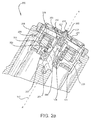
FIG. 2a illustrates a schematic cross-section view of a park brake system in accordance with various embodiments; -
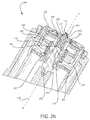
FIG. 2b illustrates a further schematic cross-section view of a park brake system in accordance with various embodiments; -
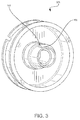
FIG. 3 illustrates a perspective view of a bobbin in accordance with various embodiments; -
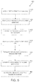
FIG. 4 illustrates a method of engaging a park brake system in accordance with various embodiments; and -
FIG. 5 illustrates a method of engaging and disengaging a park brake system in accordance with various embodiments. - The detailed description of various embodiments herein makes reference to the accompanying drawings, which show various embodiments by way of illustration. While these various embodiments are described in sufficient detail to enable those skilled in the art to practice the disclosure, it should be understood that other embodiments may be realized and that logical, chemical, and mechanical changes may be made without departing from the scope of the disclosure. Thus, the detailed description herein is presented for purposes of illustration only and not of limitation.
- For example, the steps recited in any of the method or process descriptions may be executed in any order and are not necessarily limited to the order presented. Furthermore, any reference to singular includes plural embodiments, and any reference to more than one component or step may include a singular embodiment or step. Also, any reference to attached, fixed, connected, or the like may include permanent, removable, temporary, partial, full, and/or any other possible attachment option. Additionally, any reference to without contact (or similar phrases) may also include reduced contact or minimal contact.
- An aircraft park brake system may comprise an end plate distal from a plurality of interleaved rotor disks and stator disks which together form a brake heat sink. Each rotor disk may be coupled to a wheel for rotation therewith and each stator disk may be coupled to a wheel support, which resists rotation. The brake mechanism also generally includes a torque tube and a back leg on which a pressure plate, end plate, and stator disks are slidably mounted against rotation relative to the wheel and rotor disks. The stator disks may comprise two wear faces and the pressure plate may comprise a single wear face. The rotor disks and stator disks may be formed of a friction material, such as a carbon/carbon or a carbon metallic matrix material. A brake head may house the piston motor or one or more rams that extend to move the pressure plate and axially compress the brake disk stack against the end plate.
- In various embodiments, a brake system may comprise a brake system controller ("BSC") coupled to one or more electromechanical actuator controllers ("EMACs"), each of which may drive an electromechanical actuator ("EMA"). The BSC may be in communication with a brake pedal, and thus may control the EMACs in accordance with pilot/copilot braking commands. The EMA may be coupled to or otherwise operate a pressure generating device, such as, for example, a ball screw, a ram, and/or the like. In operation, the EMA may cause the pressure generating device to move and/or exert a force on other brake system structures, such as a brake disk or pad to exert a stopping force on a wheel or other suitable moving structure. This stopping force may load and/or exert a corresponding force on the EMA structures such as, for example, an EMA housing.
- Referring to
FIG. 1 , a perspective view of anEMA 10 is shown in accordance with various embodiments. The EMA may extend along anaxis 102 marked A-A', with A being located near a proximal portion of EMA 10 and A' being near a distal portion of EMA 10. The EMA 10 may, as described above, be involved in the application of a braking force to the aircraft wheel. The EMA 10 may comprise an EMAhousing 101, which may extend along theaxis 102. The EMAhousing 101 may house a variety of components, including, for example, aball nut 14, aball screw 16, and a motor drive unit. Generally, the motor drive unit may drive the ball screw 16 through a plurality of rotations. As theball screw 16 rotates, theball nut 14 may translate distally and/or proximally along the axis 102 (depending upon the direction of rotation of the ball screw 16). Theball nut 14 may be coupled to a disc or "puck" at a proximal end thereof. The puck may exert a pressure against a brake stack coupled to an aircraft wheel to impede or halt a rolling motion of the wheel. The EMA may include a park brake system. For example, the EMA may comprise a bi-stable park brake system as described herein. - With reference to
FIGs. 2a and2b , apark brake system 200, in accordance with various embodiments, may comprise amotor shaft 201 having afirst diameter portion 202 and asecond diameter portion 203. Themotor shaft 201 may be disposed axially about anaxis 102. Thesecond diameter portion 203 may have a greater diameter than thefirst diameter portion 202. Themotor shaft 201 may contain an abrupt change in diameter between thefirst diameter portion 202 and thesecond diameter portion 203. - The
park brake system 200 may further comprise awire coil 204 disposed at least partially around a circumference of abobbin 205. Thewire coil 204 may comprise a wire or other conductive material that is wound at least partially around a circumference of abobbin 205. Thewire coil 204 may comprise copper or any other material now known or hereinafter developed capable of creating a magnetic field in response to conducting an electrical current. - The bobbin may comprise a radial disk portion and a circumferential flange portion, wherein the circumferential flange portion extends in a distal direction from an outer circumference of the radial disk portion. The
bobbin 205 may comprise a ferromagnetic material and/or may comprise a ferromagnetic insert. In various embodiments, a plurality of ferromagnetic inserts may be disposed in apertures of thebobbin 205. In various embodiments, thepark brake system 200 may comprise anannular bobbin washer 206 disposed coaxial to themotor shaft 201 and distal to the radial disk portion of thebobbin 205. Theannular bobbin washer 206 may be operatively coupled to thebobbin 205 and may comprise ferromagnetic material. - The
park brake system 200 may further comprise aspring 207 disposed at least partially around a circumference of themotor shaft 201. Thespring 207 may exert a proximal force on the bobbin 205 (i.e., towards A along axis 102). - The
park brake system 200 may further comprise a one-way clutch 210 housed at least partially in thebobbin 205. The one-way clutch 210 may be disposed coaxial to themotor shaft 201 alongaxis 102. The one-way clutch 210 is not particularly limited according to various embodiments and, thus, may include any now known or hereinafter developed one-way clutch. For example, various one-way clutches may include any one of an HF type one-way clutch, an HFL type one-way clutch, an NCM type one-way clutch, an NHF type one-way clutch, an NCU type one-way clutch, an NCZ type one-way clutch, an NCZC type one-way clutch, an NCZX type one-way clutch, and an NCUX type one-way clutch, all commercially available from the NTN® Corporation. - The
park brake system 200 may further comprise anannular magnet 211 and anannular steel ring 208. Theannular magnet 211 and theannular steel ring 208 may be disposed coaxial to themotor shaft 201 and distal to the radial disk portion of thebobbin 205. In various embodiments, theannular magnet 211 is disposed distal of theannular steel ring 208. Accordingly, in various embodiments,wire coil 204,bobbin 205,annular steel ring 208, andannular magnet 211 may form a voice coil assembly. - In response to a first voltage being applied to the
wire coil 204, a magnetic axial force may be generated by a flux field created by thewire coil 204 and theannular magnet 211. Theannular steel ring 208 may be made from a ferromagnetic material and may be disposed relative to thewire coil 204 such that the magnetic axial force acts in a distal direction. Stated differently, the magnetic axial force may act in a direction opposite the proximal force exerted by thespring 207. - In response to the magnetic axial force, the
bobbin 205, which is operatively coupled to the one-way clutch 210, may translate axially in a first direction. The first direction may be in a distal direction relative to themotor shaft 201. Thebobbin 205 and one-way clutch 210 may translate from thefirst diameter portion 202 at least partially to thesecond diameter portion 203, causing the one-way clutch 210 to engage themotor shaft 201 about thesecond diameter portion 203. In various embodiments, thebobbin 205 and one-way clutch 210 may translate distally for a first distance such that the one-way clutch 210 partially surrounds thefirst diameter portion 202 and partially surrounds thesecond diameter portion 203. In various embodiments, thebobbin 205 and one-way clutch 210 may translate distally for a second distance such that the one-way clutch 210 surrounds thesecond diameter portion 203, but does not surround thefirst diameter portion 202. - With reference to
FIG. 2a , thepark brake system 200 is illustrated in an engaged state. In that regard, the one-way clutch 201 is at least partially engaged to themotor shaft 201 about thesecond diameter portion 203 and constrains themotor shaft 201 from rotating in a first rotational direction. As previously described, in various embodiments, a first voltage may be applied to thewire coil 204 and, thus, thebobbin 205 and the one-way clutch 210 may translate axially. Thebobbin 205 may translate axially until contacting theannular steel ring 208 and/or until theannular bobbin washer 206 contacts theannular steel ring 208. In various embodiments, the magnetic axial force acting on thebobbin 205 in a distal direction may be greater than the force of thespring 207 acting on thebobbin 205 in a proximal direction. - The
bobbin 205 may be held in contact with theannular steel ring 208 due to the proximity of thebobbin 205 and/or theannular bobbin washer 206 to theannular magnet 211. Thus, in various embodiments, the one-way clutch 210 may maintain engagement with thesecond diameter portion 203 of themotor shaft 201. Engagement of the one-way clutch 210 with themotor shaft 201 may prevent rotation of themotor shaft 201 in a first rotational direction. In various embodiments,annular magnet 211 may be a permanent magnet. In that regard,annular magnet 211 may constrainbobbin 205 and/or theannular bobbin washer 206 from axial movement without drawing external electrical energy. In that regard,park brake system 200 is in a stable engaged state in that no external energy is used to maintainpark brake system 200 in an engaged state. - With reference to
FIG. 2b , thepark brake system 200 is illustrated in a disengaged state. In that regard, the one-way clutch 210 is disposed about thefirst diameter portion 202 and is not engaged to themotor shaft 201. In a disengaged state, the one-way clutch 210 does not constrain themotor shaft 201 from rotating in a first rotational direction. In response to a second voltage being applied to thewire coil 204, the one-way clutch 210 may translate axially in a second direction. In various embodiments, the second voltage may be reversed relative to the first voltage and the second direction may be in a proximal direction relative to themotor shaft 201. In various embodiments, application of the second voltage may allow the force of thespring 207 acting on thebobbin 205 in a proximal direction to overcome the force of theannular magnet 211 acting on thebobbin 205 in a distal direction. Thebobbin 205 and the one-way clutch 210 may be translated proximally until they are disposed about thefirst diameter portion 202 of themotor shaft 201. In various embodiments, thespring 207 may constrain thebobbin 205 and/or theannular bobbin washer 206 from axial movement without drawing external electrical energy. In that regard,park brake system 200 is in a stable disengaged state in that no external energy is used to maintainpark brake system 200 in a disengaged state. - With reference again to
FIGs. 2a and2b , thepark brake system 200 may further comprise a clutch release mechanism disposed coaxial to themotor shaft 201 and around thefirst diameter portion 202. In various embodiments, the clutch release mechanism may comprise a clutch release bearing 212 and a clutchrelease bearing support 213. The clutch release bearing 212 may be disposed coaxial to themotor shaft 201 and around thefirst diameter portion 202. The clutchrelease bearing support 213 may be disposed coaxial to themotor shaft 201 and between thefirst diameter portion 202 and the clutch release bearing 212. - In various embodiments and with reference to
FIG. 2b , the one-way clutch 210 may be configured to engage with the clutch release bearing 212 when thepark brake system 200 is in a disengaged state. Engagement of the one-way clutch 210 to the clutch release bearing 212 may prevent rotation of the clutch release bearing 212 in a first rotational direction. The clutchrelease bearing support 213 may be configured to freely rotate within the clutch release bearing 212. Thus, engagement of the one-way clutch 210 to the clutch release bearing 212 may not prevent rotation of the clutchrelease bearing support 213 or themotor shaft 201 in either direction. In various embodiments, the clutchrelease bearing support 213 may comprise a low-friction material; however, clutchrelease bearing support 213 may comprise any material suitable to allow rotation of the clutchrelease bearing support 213 and/or themotor shaft 201 within the clutch release bearing 212 in response to being engaged with the one-way clutch 210. - The clutch release mechanism may further comprise a clutch
release bearing nut 214. The clutchrelease bearing nut 214 may be disposed coaxial to themotor shaft 201, around thefirst diameter portion 202, and proximal to the clutchrelease bearing support 213. In various embodiments, the clutchrelease bearing nut 214 may be operatively coupled to themotor shaft 201 and may be configured to prevent the movement of the clutch release bearing 212 and/or the clutchrelease bearing support 213 in a proximal direction relative to themotor shaft 201. - In various embodiments and with reference to
FIG. 3 , thebobbin 205 may comprise ananti-rotation guide 301. Theanti-rotation guide 301 may comprise a buttress or ridge disposed on, and partially surrounding, an inner circumference of thebobbin 205. Theanti-rotation guide 301 may further comprise ananti-rotation face 302 disposed at an end of theanti-rotation guide 301. - In various embodiments and referring back to
FIGs. 2a and2b , thepark brake system 200 may further comprise avoice coil housing 220. Thevoice coil housing 220 may be disposed coaxial to themotor shaft 201 and may comprise an outer circumferential flange and an inner flange. Thevoice coil housing 220 may be disposed such that the outer flange at least partially surrounds thewire coil 204,bobbin 205,annular steel ring 208, andannular magnet 211. The inner flange may partially surround the inner circumference of thebobbin 205. Thevoice coil housing 220 may be configured such that it does not rotate relative to theEMA housing 101. In various embodiments, ananti-rotation stop 221 may be disposed on the inner flange of thevoice coil housing 220. Theanti-rotation stop 221 may be configured to align with theanti-rotation face 302 when thepark brake system 200 is in an engaged state. - With reference to
FIG. 2a , engagement of the one-way clutch 210 to themotor shaft 201 may prevent rotation of themotor shaft 201 relative to the one-way clutch 210 in a first rotational direction. Thus, rotational force acting on themotor shaft 201 in the first rotational direction may be translated both to the one-way clutch 210 and also to thebobbin 205, to which the one-way clutch 210 may be operatively coupled. Rotation of thebobbin 205 in the first rotational direction may be prevented by theanti-rotation stop 221, which may be configured to align with theanti-rotation face 302 of thebobbin 205. When thepark brake system 200 is in an engaged state, theanti-rotation stop 221 may be aligned axially and radially with theanti-rotation face 302; stated differently, at least a portion of theanti-rotation stop 221 and theanti-rotation face 302 may be disposed at the same axial point along theaxis 102 and at the same radial distance from theaxis 102. Rotational force acting on themotor shaft 210 may cause thebobbin 205 to rotate around theaxis 102 until theanti-rotation face 302 contacts theanti-rotation stop 221. Such contact may constrain thebobbin 205, the one-way clutch 210, and themotor shaft 201 from further rotation. - In various embodiments and with reference to
FIGs. 2a and2b , thepark brake system 200 may further comprise adamper mechanism 222. Thedamper mechanism 222 may be disposed coaxially around themotor shaft 201 and proximal of thebobbin 205. In response to a first voltage being applied to thewire coil 204, thebobbin 205 and one-way clutch 210 may translate axially in a proximal first direction relative to themotor shaft 201. In various embodiments, translation of thebobbin 205 and one-way clutch 210 may be at high velocity and/or acceleration. Thebobbin 205 and one-way clutch 210 may impact other portions of thepark brake system 200 during or at the termination of axial translation in a proximal first direction, causing stress, wear, or damage to the system components. Thedamper mechanism 222 may be configured to decrease the velocity and/or dissipate the kinetic energy of thebobbin 205 and one-way clutch 210 as they translate axially in a proximal first direction. Thedamper mechanism 222 may comprise a spring, washer, pad, hydraulic mechanism, or any other suitable mechanism for dissipating kinetic energy. - With reference to
FIGs. 2a and4 , amethod 400 of engaging apark brake system 200 may comprise applying a first voltage to a wire coil 204 (Step 410). In various embodiments, thewire coil 204 may be disposed at least partially around a circumference of abobbin 205, wherein a one-way clutch 210 is disposed at least partially within thebobbin 205 and coaxial to amotor shaft 201 having afirst diameter portion 202 and asecond diameter portion 203, thesecond diameter portion 203 having a greater diameter than thefirst diameter portion 202. In various embodiments, the first voltage may be applied by an EMAC.Method 400 may also comprise translating a one-way 210 clutch axially in a first direction with respect to the motor shaft 201 (Step 420). In various embodiments,method 400 may comprise engaging the one-way clutch 210 to the second diameter portion 203 (Step 430). The rotation of themotor shaft 201 may be prevented in a first rotational direction in response to engagement of the one-way clutch to the motor shaft. - With reference to
FIGs. 2a ,2b , and5 , amethod 500 of engaging and disengaging apark brake system 200 may comprise applying a first voltage to a wire coil 204 (Step 410). In various embodiments, thewire coil 204 may be disposed at least partially around a circumference of abobbin 205, wherein a one-way clutch 210 is disposed at least partially within thebobbin 205 and coaxial to amotor shaft 201 having afirst diameter portion 202 and asecond diameter portion 203, thesecond diameter portion 203 having a greater diameter than thefirst diameter portion 202. In various embodiments, the first voltage may be applied by an EMAC. -
Method 500 may further comprise translating a one-way clutch 210 axially in a first direction with respect to the motor shaft 201 (Step 420). In various embodiments,method 500 may comprise engaging the one-way clutch 210 to the second diameter portion 203 (Step 430). The rotation of themotor shaft 201 may be prevented in a first rotational direction in response to engagement of the one-way clutch 210 to themotor shaft 201. -
Method 500 may further comprise applying a second voltage to the wire coil 204 (Step 540). In various embodiments,method 500 may include translating the one-way clutch 210 axially in a second direction (Step 550) and disposing the one-way clutch 210 about thefirst diameter portion 202 of the motor shaft 201 (Step 560). In various embodiments, disposing the one-way clutch 210 about thefirst diameter portion 202 may disengage the one-way clutch 210 from thesecond diameter portion 203 of themotor shaft 201, allowing rotation of themotor shaft 201 in a first rotational direction. -
Method 500 is not particularly limited and may further comprise dissipating a kinetic energy of the one-way clutch 210 as it translates in the second direction (Step 570). The kinetic energy may be dissipated by adamper mechanism 222 disposed coaxial to themotor shaft 201 and proximal to thebobbin 205. - Benefits, other advantages, and solutions to problems have been described herein with regard to specific embodiments. Furthermore, the connecting lines shown in the various figures contained herein are intended to represent exemplary functional relationships and/or physical couplings between the various elements. It should be noted that many alternative or additional functional relationships or physical connections may be present in a practical system. However, the benefits, advantages, solutions to problems, and any elements that may cause any benefit, advantage, or solution to occur or become more pronounced are not to be construed as critical, required, or essential features or elements of the disclosure. The scope of the disclosure is accordingly to be limited by nothing other than the appended claims, in which reference to an element in the singular is not intended to mean "one and only one" unless explicitly so stated, but rather "one or more." Moreover, where a phrase similar to "at least one of A, B, or C" is used in the claims, it is intended that the phrase be interpreted to mean that A alone may be present in an embodiment, B alone may be present in an embodiment, C alone may be present in an embodiment, or that any combination of the elements A, B and C may be present in a single embodiment; for example, A and B, A and C, B and C, or A and B and C. Different cross-hatching is used throughout the figures to denote different parts but not necessarily to denote the same or different materials.
- Devices and methods are provided herein. In the detailed description herein, references to "one embodiment", "an embodiment", "various embodiments" etc., indicate that the embodiment described may include a particular feature, structure, or characteristic, but every embodiment may not necessarily include the particular feature, structure, or characteristic. Moreover, such phrases are not necessarily referring to the same embodiment. Further, when a particular feature, structure, or characteristic is described in connection with an embodiment, it is submitted that it is within the knowledge of one skilled in the art to affect such feature, structure, or characteristic in connection with other embodiments whether or not explicitly described. After reading the description, it will be apparent to one skilled in the relevant art(s) how to implement the disclosure in alternative embodiments.
- As used herein, the terms "comprises", "comprising", or any other variation thereof, are intended to cover a non-exclusive inclusion, such that a process, method, article, or apparatus that comprises a list of elements does not include only those elements but may include other elements not expressly listed or inherent to such process, method, article, or apparatus.
Claims (15)
- A park brake system, comprising:a motor shaft (201) having a first diameter portion (202) and a second diameter portion (203), the second diameter portion having a greater diameter than the first diameter portion,a spring (207) disposed at least partially around a circumference of the motor shaft,a wire coil (204) disposed at least partially around a circumference of a bobbin (205),a one-way clutch (210) disposed at least partially within the bobbin and coaxial to the motor shaft,an annular magnet (211) disposed coaxial to the motor shaft and distal to at least a portion of the bobbin, anda clutch release mechanism disposed coaxial to the motor shaft and around the first diameter portion,wherein, in response to a first voltage applied to the wire coil, the one-way clutch translates axially in a first direction relative to the motor shaft and engages with the second diameter portion, and
wherein, in response to a second voltage applied to the wire coil, the one-way clutch translates axially in a second direction relative to the motor shaft and engages with the clutch release mechanism. - The park brake system of claim 1, wherein the clutch release mechanism further comprises:a clutch release bearing (212) disposed coaxial to the motor shaft and around the first diameter portion,a clutch release bearing support (213) disposed coaxial to the motor shaft and between the clutch release bearing and the first diameter portion, anda clutch release bearing nut (214) disposed coaxial to the motor shaft, around the first diameter portion, and proximal to the clutch release bearing support.
- The park brake system of claim 2, wherein the one-way clutch is disposed to prevent rotation of the motor shaft in a first rotational direction in response to engagement with the second diameter portion.
- The park brake system of claim 3, further comprising an annular bobbin washer (206) disposed coaxial to the motor shaft, proximal to the annular magnet, and distal to at least a portion of the bobbin.
- The park brake system of claim 3 or 4, wherein the bobbin comprises a ferromagnetic insert.
- The park brake system of claim 3, 4 or 5, wherein the second voltage is reversed relative to the first voltage.
- The park brake system of claim 3, 4, 5 or 6, wherein the spring exerts a proximal force on the bobbin.
- The park brake system of any of claims 3 to7, further comprising:an anti-rotation stop (221) disposed on a voice coil housing (220), andan anti-rotation guide (301) disposed on the bobbin and having an anti-rotation face,wherein, in response to the one-way clutch engaging with the second diameter portion, the anti-rotation stop and the anti-rotation face are disposed adjacent to one another.
- The park brake system of any of claims 3 to 8, further comprising a damper mechanism (222) disposed coaxial to the motor shaft and proximal to the bobbin.
- An electromechanical actuator ("EMA"), comprising the park brake system of any preceding claim.
- A method comprising:applying a first voltage to a wire coil disposed at least partially around a circumference of a bobbin, wherein a one-way clutch is disposed at least partially within the bobbin and coaxial to a motor shaft having a first diameter portion and a second diameter portion, the second diameter portion having a greater diameter than the first diameter portion,translating the one-way clutch axially in a first direction with respect to the motor shaft, andengaging the one-way clutch to the second diameter portion, wherein rotation of the motor shaft is prevented in a first rotational direction in response to engagement of the one-way clutch with the motor shaft.
- The method of claim 11, further comprising:applying a second voltage to the wire coil,translating the one-way clutch axially in a second direction,disposing the one-way clutch around the first diameter portion, andengaging the one-way clutch to a clutch release mechanism disposed coaxial to the motor shaft and around the first diameter portion.
- The method of claim 12, further comprising:dissipating a kinetic energy of the one-way clutch as it translates in the second direction by a damper mechanism disposed coaxial to the motor shaft and proximal to the bobbin.
- The method of claim 12,
wherein, in response to engagement of the one-way clutch with the second diameter portion, rotation of the motor shaft is prevented in a first rotational direction, and
wherein, in response to engagement of the one-way clutch with the clutch release mechanism, rotation of the motor shaft is not prevented in the first rotational direction. - The method of claim 12, wherein the first voltage is applied by an electromechanical actuator controller ("EMAC").
Applications Claiming Priority (1)
| Application Number | Priority Date | Filing Date | Title |
|---|---|---|---|
| US14/597,732 US9586678B2 (en) | 2015-01-15 | 2015-01-15 | Bi-stable voice coil park brake |
Publications (2)
| Publication Number | Publication Date |
|---|---|
| EP3045361A1 true EP3045361A1 (en) | 2016-07-20 |
| EP3045361B1 EP3045361B1 (en) | 2019-12-11 |
Family
ID=55129665
Family Applications (1)
| Application Number | Title | Priority Date | Filing Date |
|---|---|---|---|
| EP16151102.7A Active EP3045361B1 (en) | 2015-01-15 | 2016-01-13 | Bi-stable voice coil park brake |
Country Status (2)
| Country | Link |
|---|---|
| US (1) | US9586678B2 (en) |
| EP (1) | EP3045361B1 (en) |
Families Citing this family (4)
| Publication number | Priority date | Publication date | Assignee | Title |
|---|---|---|---|---|
| GB201515171D0 (en) * | 2015-08-26 | 2015-10-07 | Renishaw Plc | Braking system |
| US10518761B2 (en) | 2016-07-01 | 2019-12-31 | Akebono Brake Industry Co., Ltd | Electric park brake with electromagnetic brake |
| US10408289B2 (en) | 2016-08-12 | 2019-09-10 | Akebono Brake Industry Co., Ltd. | Parking brake torque locking mechanism |
| US10106139B2 (en) | 2017-02-02 | 2018-10-23 | Goodrich Corporation | Brake systems and methods |
Citations (7)
| Publication number | Priority date | Publication date | Assignee | Title |
|---|---|---|---|---|
| FR2135689A5 (en) * | 1971-03-09 | 1972-12-22 | Potain Sa | |
| DE19752543A1 (en) * | 1997-11-27 | 1999-06-02 | Bosch Gmbh Robert | Magnetic brake and electromechanical braking device with a magnetic brake |
| WO2002049892A1 (en) * | 2000-12-20 | 2002-06-27 | Haldex Brake Products Ab | A spring brake actuator |
| DE10233673A1 (en) * | 2001-07-31 | 2003-03-20 | Tokico Ltd | Electric brake for vehicle braking, has mechanism for locking parking brake that can prevent rotor rotation in brake release direction when current to motor is interrupted |
| US20070068765A1 (en) * | 2005-09-27 | 2007-03-29 | Keiichi Koga | One-way clutch and electric parking brake device using the same |
| DE102006023447A1 (en) * | 2006-05-18 | 2007-11-22 | Arvinmeritor Light Vehicle Systems-France | Electromechanical coupling |
| US20150008091A1 (en) * | 2013-07-02 | 2015-01-08 | Goodrich Corporation | Wrap spring park brake system, apparatus and method |
Family Cites Families (13)
| Publication number | Priority date | Publication date | Assignee | Title |
|---|---|---|---|---|
| US2430174A (en) * | 1943-11-06 | 1947-11-04 | Electrical Engineering And Mfg | Electromagnetic clutch and brake |
| US2949172A (en) * | 1958-12-16 | 1960-08-16 | Us Electrical Motors Inc | Positive lock electromagnetic brake structure |
| SE460782B (en) * | 1988-03-21 | 1989-11-20 | Sab Nife Ab | ELECTROMECHANICAL BRAKE UNIT |
| US5219049A (en) * | 1991-06-24 | 1993-06-15 | General Motors Corporation | Electrically actuated electric brake with adjuster |
| US5185542A (en) | 1991-08-28 | 1993-02-09 | Electroid Company | Electromagnetic pulse operated bi-stable brake |
| DE29611732U1 (en) * | 1996-07-05 | 1996-09-05 | Mayr Christian Gmbh & Co Kg | Electromagnetically released friction safety brake with two brake discs and an axially displaceable, non-rotatable electromagnet |
| DE19652229A1 (en) * | 1996-12-16 | 1998-06-18 | Bosch Gmbh Robert | Electromechanically operated brake |
| DE19851196A1 (en) * | 1998-11-06 | 2000-05-25 | Harting Kgaa | Electromagnetically actuated brake, especially holding brake, has ferromagnetic, twist-proof cam plate with cams engaging in openings in rotatable part to be braked in shape-locking manner |
| SE520255C2 (en) * | 2000-12-20 | 2003-06-17 | Haldex Brake Prod Ab | Way and device for service braking |
| ITTO20011164A1 (en) * | 2001-12-13 | 2003-06-13 | Skf Ind Spa | SCREW ACTUATOR WITH BRAKE. |
| US7063190B1 (en) * | 2003-09-09 | 2006-06-20 | Mpc Products Corporation | Braking system |
| DE102006018094A1 (en) * | 2005-11-29 | 2007-05-31 | Robert Bosch Gmbh | Locking device e.g. in motor vehicle, has locking elements which in locking position are capable of interlocked in axial direction by form-closure to each other |
| US9308990B2 (en) * | 2014-05-30 | 2016-04-12 | Goodrich Corporation | Voice coil linear activated park brake |
-
2015
- 2015-01-15 US US14/597,732 patent/US9586678B2/en active Active
-
2016
- 2016-01-13 EP EP16151102.7A patent/EP3045361B1/en active Active
Patent Citations (7)
| Publication number | Priority date | Publication date | Assignee | Title |
|---|---|---|---|---|
| FR2135689A5 (en) * | 1971-03-09 | 1972-12-22 | Potain Sa | |
| DE19752543A1 (en) * | 1997-11-27 | 1999-06-02 | Bosch Gmbh Robert | Magnetic brake and electromechanical braking device with a magnetic brake |
| WO2002049892A1 (en) * | 2000-12-20 | 2002-06-27 | Haldex Brake Products Ab | A spring brake actuator |
| DE10233673A1 (en) * | 2001-07-31 | 2003-03-20 | Tokico Ltd | Electric brake for vehicle braking, has mechanism for locking parking brake that can prevent rotor rotation in brake release direction when current to motor is interrupted |
| US20070068765A1 (en) * | 2005-09-27 | 2007-03-29 | Keiichi Koga | One-way clutch and electric parking brake device using the same |
| DE102006023447A1 (en) * | 2006-05-18 | 2007-11-22 | Arvinmeritor Light Vehicle Systems-France | Electromechanical coupling |
| US20150008091A1 (en) * | 2013-07-02 | 2015-01-08 | Goodrich Corporation | Wrap spring park brake system, apparatus and method |
Also Published As
| Publication number | Publication date |
|---|---|
| US20160207613A1 (en) | 2016-07-21 |
| US9586678B2 (en) | 2017-03-07 |
| EP3045361B1 (en) | 2019-12-11 |
Similar Documents
| Publication | Publication Date | Title |
|---|---|---|
| EP3045361B1 (en) | Bi-stable voice coil park brake | |
| CN108137025B (en) | Electromechanical actuator | |
| EP2965961B1 (en) | Voice coil linear activated park brake | |
| EP2633603B1 (en) | Electric motor | |
| US11780419B2 (en) | Electric park brake with electromagnetic brake | |
| JPH11201191A (en) | Lap spring clutch assembly | |
| US9933059B2 (en) | Dual-rate linear actuator | |
| EP2982557B1 (en) | Apparatus and system for aircraft park brake systems | |
| CN108349481B (en) | Electromechanical actuator | |
| EP3631229A1 (en) | Magnetically actuated brake | |
| EP2965987A1 (en) | Belt park brake and method | |
| EP2336591A1 (en) | Electric motor with passive integral brake | |
| CN111664202A (en) | Linear driving device | |
| US9732817B2 (en) | Axial engagement-controlled variable damper systems and methods | |
| CA2964885C (en) | Positioning of disks in the brake released mode for multi disk brakes | |
| EP3156326B1 (en) | Axial engagement-controlled variable damper systems and methods | |
| US11136010B2 (en) | Motor with a cone clutch motor brake | |
| EP4240984A1 (en) | Brake device, drive unit, and industrial device | |
| CN113059592A (en) | Robot movement mechanism | |
| CN216241931U (en) | Brake for power-off | |
| EP4332406A1 (en) | Brake for motor | |
| CN116601403A (en) | Braking device, motor and robot |
Legal Events
| Date | Code | Title | Description |
|---|---|---|---|
| PUAI | Public reference made under article 153(3) epc to a published international application that has entered the european phase |
Free format text: ORIGINAL CODE: 0009012 |
|
| AK | Designated contracting states |
Kind code of ref document: A1 Designated state(s): AL AT BE BG CH CY CZ DE DK EE ES FI FR GB GR HR HU IE IS IT LI LT LU LV MC MK MT NL NO PL PT RO RS SE SI SK SM TR |
|
| AX | Request for extension of the european patent |
Extension state: BA ME |
|
| STAA | Information on the status of an ep patent application or granted ep patent |
Free format text: STATUS: REQUEST FOR EXAMINATION WAS MADE |
|
| 17P | Request for examination filed |
Effective date: 20170119 |
|
| RBV | Designated contracting states (corrected) |
Designated state(s): AL AT BE BG CH CY CZ DE DK EE ES FI FR GB GR HR HU IE IS IT LI LT LU LV MC MK MT NL NO PL PT RO RS SE SI SK SM TR |
|
| GRAP | Despatch of communication of intention to grant a patent |
Free format text: ORIGINAL CODE: EPIDOSNIGR1 |
|
| STAA | Information on the status of an ep patent application or granted ep patent |
Free format text: STATUS: GRANT OF PATENT IS INTENDED |
|
| INTG | Intention to grant announced |
Effective date: 20190621 |
|
| GRAS | Grant fee paid |
Free format text: ORIGINAL CODE: EPIDOSNIGR3 |
|
| GRAA | (expected) grant |
Free format text: ORIGINAL CODE: 0009210 |
|
| STAA | Information on the status of an ep patent application or granted ep patent |
Free format text: STATUS: THE PATENT HAS BEEN GRANTED |
|
| AK | Designated contracting states |
Kind code of ref document: B1 Designated state(s): AL AT BE BG CH CY CZ DE DK EE ES FI FR GB GR HR HU IE IS IT LI LT LU LV MC MK MT NL NO PL PT RO RS SE SI SK SM TR |
|
| REG | Reference to a national code |
Ref country code: GB Ref legal event code: FG4D |
|
| REG | Reference to a national code |
Ref country code: CH Ref legal event code: EP |
|
| REG | Reference to a national code |
Ref country code: AT Ref legal event code: REF Ref document number: 1211900 Country of ref document: AT Kind code of ref document: T Effective date: 20191215 |
|
| REG | Reference to a national code |
Ref country code: DE Ref legal event code: R096 Ref document number: 602016025847 Country of ref document: DE |
|
| REG | Reference to a national code |
Ref country code: IE Ref legal event code: FG4D |
|
| REG | Reference to a national code |
Ref country code: NL Ref legal event code: MP Effective date: 20191211 |
|
| REG | Reference to a national code |
Ref country code: LT Ref legal event code: MG4D |
|
| PG25 | Lapsed in a contracting state [announced via postgrant information from national office to epo] |
Ref country code: LV Free format text: LAPSE BECAUSE OF FAILURE TO SUBMIT A TRANSLATION OF THE DESCRIPTION OR TO PAY THE FEE WITHIN THE PRESCRIBED TIME-LIMIT Effective date: 20191211 Ref country code: SE Free format text: LAPSE BECAUSE OF FAILURE TO SUBMIT A TRANSLATION OF THE DESCRIPTION OR TO PAY THE FEE WITHIN THE PRESCRIBED TIME-LIMIT Effective date: 20191211 Ref country code: NO Free format text: LAPSE BECAUSE OF FAILURE TO SUBMIT A TRANSLATION OF THE DESCRIPTION OR TO PAY THE FEE WITHIN THE PRESCRIBED TIME-LIMIT Effective date: 20200311 Ref country code: GR Free format text: LAPSE BECAUSE OF FAILURE TO SUBMIT A TRANSLATION OF THE DESCRIPTION OR TO PAY THE FEE WITHIN THE PRESCRIBED TIME-LIMIT Effective date: 20200312 Ref country code: LT Free format text: LAPSE BECAUSE OF FAILURE TO SUBMIT A TRANSLATION OF THE DESCRIPTION OR TO PAY THE FEE WITHIN THE PRESCRIBED TIME-LIMIT Effective date: 20191211 Ref country code: FI Free format text: LAPSE BECAUSE OF FAILURE TO SUBMIT A TRANSLATION OF THE DESCRIPTION OR TO PAY THE FEE WITHIN THE PRESCRIBED TIME-LIMIT Effective date: 20191211 Ref country code: BG Free format text: LAPSE BECAUSE OF FAILURE TO SUBMIT A TRANSLATION OF THE DESCRIPTION OR TO PAY THE FEE WITHIN THE PRESCRIBED TIME-LIMIT Effective date: 20200311 |
|
| PG25 | Lapsed in a contracting state [announced via postgrant information from national office to epo] |
Ref country code: HR Free format text: LAPSE BECAUSE OF FAILURE TO SUBMIT A TRANSLATION OF THE DESCRIPTION OR TO PAY THE FEE WITHIN THE PRESCRIBED TIME-LIMIT Effective date: 20191211 Ref country code: RS Free format text: LAPSE BECAUSE OF FAILURE TO SUBMIT A TRANSLATION OF THE DESCRIPTION OR TO PAY THE FEE WITHIN THE PRESCRIBED TIME-LIMIT Effective date: 20191211 |
|
| PG25 | Lapsed in a contracting state [announced via postgrant information from national office to epo] |
Ref country code: AL Free format text: LAPSE BECAUSE OF FAILURE TO SUBMIT A TRANSLATION OF THE DESCRIPTION OR TO PAY THE FEE WITHIN THE PRESCRIBED TIME-LIMIT Effective date: 20191211 |
|
| PG25 | Lapsed in a contracting state [announced via postgrant information from national office to epo] |
Ref country code: CZ Free format text: LAPSE BECAUSE OF FAILURE TO SUBMIT A TRANSLATION OF THE DESCRIPTION OR TO PAY THE FEE WITHIN THE PRESCRIBED TIME-LIMIT Effective date: 20191211 Ref country code: PT Free format text: LAPSE BECAUSE OF FAILURE TO SUBMIT A TRANSLATION OF THE DESCRIPTION OR TO PAY THE FEE WITHIN THE PRESCRIBED TIME-LIMIT Effective date: 20200506 Ref country code: NL Free format text: LAPSE BECAUSE OF FAILURE TO SUBMIT A TRANSLATION OF THE DESCRIPTION OR TO PAY THE FEE WITHIN THE PRESCRIBED TIME-LIMIT Effective date: 20191211 Ref country code: EE Free format text: LAPSE BECAUSE OF FAILURE TO SUBMIT A TRANSLATION OF THE DESCRIPTION OR TO PAY THE FEE WITHIN THE PRESCRIBED TIME-LIMIT Effective date: 20191211 Ref country code: ES Free format text: LAPSE BECAUSE OF FAILURE TO SUBMIT A TRANSLATION OF THE DESCRIPTION OR TO PAY THE FEE WITHIN THE PRESCRIBED TIME-LIMIT Effective date: 20191211 Ref country code: RO Free format text: LAPSE BECAUSE OF FAILURE TO SUBMIT A TRANSLATION OF THE DESCRIPTION OR TO PAY THE FEE WITHIN THE PRESCRIBED TIME-LIMIT Effective date: 20191211 |
|
| REG | Reference to a national code |
Ref country code: DE Ref legal event code: R119 Ref document number: 602016025847 Country of ref document: DE |
|
| PG25 | Lapsed in a contracting state [announced via postgrant information from national office to epo] |
Ref country code: SK Free format text: LAPSE BECAUSE OF FAILURE TO SUBMIT A TRANSLATION OF THE DESCRIPTION OR TO PAY THE FEE WITHIN THE PRESCRIBED TIME-LIMIT Effective date: 20191211 Ref country code: IS Free format text: LAPSE BECAUSE OF FAILURE TO SUBMIT A TRANSLATION OF THE DESCRIPTION OR TO PAY THE FEE WITHIN THE PRESCRIBED TIME-LIMIT Effective date: 20200411 Ref country code: SM Free format text: LAPSE BECAUSE OF FAILURE TO SUBMIT A TRANSLATION OF THE DESCRIPTION OR TO PAY THE FEE WITHIN THE PRESCRIBED TIME-LIMIT Effective date: 20191211 |
|
| REG | Reference to a national code |
Ref country code: CH Ref legal event code: PL |
|
| PG25 | Lapsed in a contracting state [announced via postgrant information from national office to epo] |
Ref country code: MC Free format text: LAPSE BECAUSE OF FAILURE TO SUBMIT A TRANSLATION OF THE DESCRIPTION OR TO PAY THE FEE WITHIN THE PRESCRIBED TIME-LIMIT Effective date: 20191211 |
|
| REG | Reference to a national code |
Ref country code: AT Ref legal event code: MK05 Ref document number: 1211900 Country of ref document: AT Kind code of ref document: T Effective date: 20191211 Ref country code: BE Ref legal event code: MM Effective date: 20200131 |
|
| PLBE | No opposition filed within time limit |
Free format text: ORIGINAL CODE: 0009261 |
|
| STAA | Information on the status of an ep patent application or granted ep patent |
Free format text: STATUS: NO OPPOSITION FILED WITHIN TIME LIMIT |
|
| PG25 | Lapsed in a contracting state [announced via postgrant information from national office to epo] |
Ref country code: LU Free format text: LAPSE BECAUSE OF NON-PAYMENT OF DUE FEES Effective date: 20200113 Ref country code: DE Free format text: LAPSE BECAUSE OF NON-PAYMENT OF DUE FEES Effective date: 20200801 Ref country code: DK Free format text: LAPSE BECAUSE OF FAILURE TO SUBMIT A TRANSLATION OF THE DESCRIPTION OR TO PAY THE FEE WITHIN THE PRESCRIBED TIME-LIMIT Effective date: 20191211 |
|
| 26N | No opposition filed |
Effective date: 20200914 |
|
| PG25 | Lapsed in a contracting state [announced via postgrant information from national office to epo] |
Ref country code: LI Free format text: LAPSE BECAUSE OF NON-PAYMENT OF DUE FEES Effective date: 20200131 Ref country code: CH Free format text: LAPSE BECAUSE OF NON-PAYMENT OF DUE FEES Effective date: 20200131 Ref country code: SI Free format text: LAPSE BECAUSE OF FAILURE TO SUBMIT A TRANSLATION OF THE DESCRIPTION OR TO PAY THE FEE WITHIN THE PRESCRIBED TIME-LIMIT Effective date: 20191211 Ref country code: BE Free format text: LAPSE BECAUSE OF NON-PAYMENT OF DUE FEES Effective date: 20200131 Ref country code: AT Free format text: LAPSE BECAUSE OF FAILURE TO SUBMIT A TRANSLATION OF THE DESCRIPTION OR TO PAY THE FEE WITHIN THE PRESCRIBED TIME-LIMIT Effective date: 20191211 |
|
| PG25 | Lapsed in a contracting state [announced via postgrant information from national office to epo] |
Ref country code: IE Free format text: LAPSE BECAUSE OF NON-PAYMENT OF DUE FEES Effective date: 20200113 Ref country code: IT Free format text: LAPSE BECAUSE OF FAILURE TO SUBMIT A TRANSLATION OF THE DESCRIPTION OR TO PAY THE FEE WITHIN THE PRESCRIBED TIME-LIMIT Effective date: 20191211 |
|
| PG25 | Lapsed in a contracting state [announced via postgrant information from national office to epo] |
Ref country code: PL Free format text: LAPSE BECAUSE OF FAILURE TO SUBMIT A TRANSLATION OF THE DESCRIPTION OR TO PAY THE FEE WITHIN THE PRESCRIBED TIME-LIMIT Effective date: 20191211 |
|
| PG25 | Lapsed in a contracting state [announced via postgrant information from national office to epo] |
Ref country code: TR Free format text: LAPSE BECAUSE OF FAILURE TO SUBMIT A TRANSLATION OF THE DESCRIPTION OR TO PAY THE FEE WITHIN THE PRESCRIBED TIME-LIMIT Effective date: 20191211 Ref country code: MT Free format text: LAPSE BECAUSE OF FAILURE TO SUBMIT A TRANSLATION OF THE DESCRIPTION OR TO PAY THE FEE WITHIN THE PRESCRIBED TIME-LIMIT Effective date: 20191211 Ref country code: CY Free format text: LAPSE BECAUSE OF FAILURE TO SUBMIT A TRANSLATION OF THE DESCRIPTION OR TO PAY THE FEE WITHIN THE PRESCRIBED TIME-LIMIT Effective date: 20191211 |
|
| PG25 | Lapsed in a contracting state [announced via postgrant information from national office to epo] |
Ref country code: MK Free format text: LAPSE BECAUSE OF FAILURE TO SUBMIT A TRANSLATION OF THE DESCRIPTION OR TO PAY THE FEE WITHIN THE PRESCRIBED TIME-LIMIT Effective date: 20191211 |
|
| P01 | Opt-out of the competence of the unified patent court (upc) registered |
Effective date: 20230522 |
|
| PGFP | Annual fee paid to national office [announced via postgrant information from national office to epo] |
Ref country code: GB Payment date: 20231219 Year of fee payment: 9 |
|
| PGFP | Annual fee paid to national office [announced via postgrant information from national office to epo] |
Ref country code: FR Payment date: 20231219 Year of fee payment: 9 |