EP3045298A1 - Composite forming apparatus - Google Patents
Composite forming apparatus Download PDFInfo
- Publication number
- EP3045298A1 EP3045298A1 EP15193969.1A EP15193969A EP3045298A1 EP 3045298 A1 EP3045298 A1 EP 3045298A1 EP 15193969 A EP15193969 A EP 15193969A EP 3045298 A1 EP3045298 A1 EP 3045298A1
- Authority
- EP
- European Patent Office
- Prior art keywords
- plies
- plate
- sheets
- composite
- ply
- Prior art date
- Legal status (The legal status is an assumption and is not a legal conclusion. Google has not performed a legal analysis and makes no representation as to the accuracy of the status listed.)
- Granted
Links
Images








Classifications
-
- B—PERFORMING OPERATIONS; TRANSPORTING
- B29—WORKING OF PLASTICS; WORKING OF SUBSTANCES IN A PLASTIC STATE IN GENERAL
- B29C—SHAPING OR JOINING OF PLASTICS; SHAPING OF MATERIAL IN A PLASTIC STATE, NOT OTHERWISE PROVIDED FOR; AFTER-TREATMENT OF THE SHAPED PRODUCTS, e.g. REPAIRING
- B29C70/00—Shaping composites, i.e. plastics material comprising reinforcements, fillers or preformed parts, e.g. inserts
- B29C70/04—Shaping composites, i.e. plastics material comprising reinforcements, fillers or preformed parts, e.g. inserts comprising reinforcements only, e.g. self-reinforcing plastics
- B29C70/28—Shaping operations therefor
- B29C70/30—Shaping by lay-up, i.e. applying fibres, tape or broadsheet on a mould, former or core; Shaping by spray-up, i.e. spraying of fibres on a mould, former or core
- B29C70/302—Details of the edges of fibre composites, e.g. edge finishing or means to avoid delamination
-
- B—PERFORMING OPERATIONS; TRANSPORTING
- B29—WORKING OF PLASTICS; WORKING OF SUBSTANCES IN A PLASTIC STATE IN GENERAL
- B29C—SHAPING OR JOINING OF PLASTICS; SHAPING OF MATERIAL IN A PLASTIC STATE, NOT OTHERWISE PROVIDED FOR; AFTER-TREATMENT OF THE SHAPED PRODUCTS, e.g. REPAIRING
- B29C70/00—Shaping composites, i.e. plastics material comprising reinforcements, fillers or preformed parts, e.g. inserts
- B29C70/04—Shaping composites, i.e. plastics material comprising reinforcements, fillers or preformed parts, e.g. inserts comprising reinforcements only, e.g. self-reinforcing plastics
- B29C70/28—Shaping operations therefor
- B29C70/40—Shaping or impregnating by compression not applied
- B29C70/42—Shaping or impregnating by compression not applied for producing articles of definite length, i.e. discrete articles
- B29C70/44—Shaping or impregnating by compression not applied for producing articles of definite length, i.e. discrete articles using isostatic pressure, e.g. pressure difference-moulding, vacuum bag-moulding, autoclave-moulding or expanding rubber-moulding
-
- B—PERFORMING OPERATIONS; TRANSPORTING
- B29—WORKING OF PLASTICS; WORKING OF SUBSTANCES IN A PLASTIC STATE IN GENERAL
- B29C—SHAPING OR JOINING OF PLASTICS; SHAPING OF MATERIAL IN A PLASTIC STATE, NOT OTHERWISE PROVIDED FOR; AFTER-TREATMENT OF THE SHAPED PRODUCTS, e.g. REPAIRING
- B29C70/00—Shaping composites, i.e. plastics material comprising reinforcements, fillers or preformed parts, e.g. inserts
- B29C70/02—Shaping composites, i.e. plastics material comprising reinforcements, fillers or preformed parts, e.g. inserts comprising combinations of reinforcements, e.g. non-specified reinforcements, fibrous reinforcing inserts and fillers, e.g. particulate fillers, incorporated in matrix material, forming one or more layers and with or without non-reinforced or non-filled layers
-
- B—PERFORMING OPERATIONS; TRANSPORTING
- B29—WORKING OF PLASTICS; WORKING OF SUBSTANCES IN A PLASTIC STATE IN GENERAL
- B29C—SHAPING OR JOINING OF PLASTICS; SHAPING OF MATERIAL IN A PLASTIC STATE, NOT OTHERWISE PROVIDED FOR; AFTER-TREATMENT OF THE SHAPED PRODUCTS, e.g. REPAIRING
- B29C70/00—Shaping composites, i.e. plastics material comprising reinforcements, fillers or preformed parts, e.g. inserts
- B29C70/04—Shaping composites, i.e. plastics material comprising reinforcements, fillers or preformed parts, e.g. inserts comprising reinforcements only, e.g. self-reinforcing plastics
- B29C70/28—Shaping operations therefor
- B29C70/54—Component parts, details or accessories; Auxiliary operations, e.g. feeding or storage of prepregs or SMC after impregnation or during ageing
-
- B—PERFORMING OPERATIONS; TRANSPORTING
- B29—WORKING OF PLASTICS; WORKING OF SUBSTANCES IN A PLASTIC STATE IN GENERAL
- B29C—SHAPING OR JOINING OF PLASTICS; SHAPING OF MATERIAL IN A PLASTIC STATE, NOT OTHERWISE PROVIDED FOR; AFTER-TREATMENT OF THE SHAPED PRODUCTS, e.g. REPAIRING
- B29C33/00—Moulds or cores; Details thereof or accessories therefor
- B29C33/20—Opening, closing or clamping
- B29C33/22—Opening, closing or clamping by rectilinear movement
-
- B—PERFORMING OPERATIONS; TRANSPORTING
- B29—WORKING OF PLASTICS; WORKING OF SUBSTANCES IN A PLASTIC STATE IN GENERAL
- B29C—SHAPING OR JOINING OF PLASTICS; SHAPING OF MATERIAL IN A PLASTIC STATE, NOT OTHERWISE PROVIDED FOR; AFTER-TREATMENT OF THE SHAPED PRODUCTS, e.g. REPAIRING
- B29C70/00—Shaping composites, i.e. plastics material comprising reinforcements, fillers or preformed parts, e.g. inserts
- B29C70/04—Shaping composites, i.e. plastics material comprising reinforcements, fillers or preformed parts, e.g. inserts comprising reinforcements only, e.g. self-reinforcing plastics
- B29C70/28—Shaping operations therefor
- B29C70/54—Component parts, details or accessories; Auxiliary operations, e.g. feeding or storage of prepregs or SMC after impregnation or during ageing
- B29C70/56—Tensioning reinforcements before or during shaping
-
- B—PERFORMING OPERATIONS; TRANSPORTING
- B29—WORKING OF PLASTICS; WORKING OF SUBSTANCES IN A PLASTIC STATE IN GENERAL
- B29L—INDEXING SCHEME ASSOCIATED WITH SUBCLASS B29C, RELATING TO PARTICULAR ARTICLES
- B29L2031/00—Other particular articles
- B29L2031/30—Vehicles, e.g. ships or aircraft, or body parts thereof
- B29L2031/3076—Aircrafts
Definitions
- the present disclosure generally relates to composite structures and, in particular, to the fabrication of composite structures. Still more particularly, the present disclosure relates to a method and apparatus for progressively forming composite structures.
- Aircraft are being designed and manufactured with greater and greater percentages of composite materials.
- Composite materials are used in aircraft to decrease the weight of the aircraft. This decreased weight improves performance features such as payload capacities and fuel efficiencies. Further, composite materials may provide longer service life for various components in an aircraft.
- Composite materials are tough, lightweight materials created by combining two or more functional components.
- a composite material may include reinforcing fibers bound in polymer resin matrix.
- the fibers may be randomly distributed chopped fibers, unidirectional, or may take the form of a woven cloth or fabric.
- thermoset composites fibers and resins are arranged and cured to form a composite structure.
- thermoplastic composites fibers and resins are heated to provide formability. While formable, the thermoplastic composite may be shaped and then allowed to cool.
- multiple plies of composite material may be placed on top of each other over a tool.
- the plies of composite material may be formed over the tool including over at least one tool radius.
- Forming the plies of composite material may form inconsistencies outside of tolerance. When the inconsistencies are outside of tolerance the composite structure may have undesirable quality. When the composite structure has undesirable quality, the composite structure may be reworked or discarded. Reworking a composite structure or discarding a composite structure may increase at least one of manufacturing time or manufacturing cost.
- one issue is to find a method and apparatus for forming composite materials that may result in a composite structure having a complex shape and a desirable quality. Further, another issue is to find a method and apparatus for forming multiple plies of composite materials over at least one tooling radius.
- An illustrative embodiment of the present disclosure provides an apparatus.
- the apparatus comprises a base, a plate, a number of movement systems, and a number of sheets.
- the number of movement systems move one of the base and the plate relative to the other.
- the number of sheets is connected to the plate.
- the apparatus comprises a base, a plate, a number of movement systems, and a number of sheets.
- the base may have a number of cavities.
- the plate may be associated with a cavity of the number of cavities.
- the number of movement systems may be within the cavity of the number of cavities.
- the number of sheets may be connected to the plate.
- a further illustrative embodiment of the present disclosure provides a method.
- the method may comprise interleaving a number of composite plies and portions of a number of sheets.
- the method may also lower a plate connected to the number of sheets.
- the method may comprise placing a first ply onto a base having a number of cavities.
- the method may also place a portion of a sheet onto the first ply.
- the method may further place a second ply onto the first ply.
- the method may further place a drape over the first ply, the second ply, and the first sheet.
- the method may also draw a vacuum under the drape.
- the method may further lower a plate connected to the sheet.
- the illustrative embodiments recognize and take into account one or more different considerations.
- the illustrative embodiments recognize and take into account that a composite structure may be formed from at least one of a thermoplastic material or a thermoset material.
- the illustrative embodiments recognize and take into account that a first composite structure may be initially formed from a first composite material. Subsequent composite structures having substantially the same shape as the first composite structure may be formed from a different composite material.
- a tool may desirably be usable with different types of composite materials.
- the illustrative embodiments recognize and take into account that it may be desirable to form a substantially flat multiple ply composite material into a complex shape without out of tolerance inconsistencies.
- the illustrative embodiments recognize and take into account that a substantially flat multiple ply composite material may be formed into a complex shape by forming the plies over a tool radius.
- the illustrative embodiments recognize and take into account that forming plies of composite material over a tool radius may result in unexpected ply shifts, tearing, splitting, or other undesirable inconsistencies.
- plies of composite material may be darted. Darts of a composite material may be portions of the composite material separated by spaces.
- the darts of the composite material may be folded over a tool radius until they touch.
- Darting a composite material may add an undesirable amount of manufacturing time. Further, forming a darted composite material may still result in undesirable inconsistencies. Yet further, darting a composite material may still produce a composite structure of undesirable quality.
- composite plies may stick to each other during forming causing inconsistencies. Sticking may be undesirable when it is desired for the plies to slip relative to each other.
- Ply slippage may be desired when plies are being formed such that an outer ply may have a longer distance to travel than an inner ply. For example, ply slippage may be desired around a bend or radius. Without ply slippage relative to each other, each ply may move the same distance or length of travel and wrinkles may result. Plies sticking to each other during forming may cause wrinkles, tearing, or other inconsistencies. These inconsistencies may be out of tolerance, which may cause the composite structure to have undesirable quality.
- the illustrative embodiments present methods and an apparatus to form a composite structure.
- the apparatus comprises a base, a plate, a number of movement systems, and a number of sheets.
- the base may have a number of cavities.
- the plate may be associated with a cavity of the number of cavities.
- the number of movement systems may be within the cavity of the number of cavities.
- the number of sheets may be connected to the plate.
- aircraft 100 has wing 102 and wing 104 attached to body 106.
- Aircraft 100 includes engine 108 attached to wing 102 and engine 110 attached to wing 104.
- Body 106 has tail section 112. Horizontal stabilizer 114, horizontal stabilizer 116, and vertical stabilizer 118 are attached to tail section 112 of body 106.
- Aircraft 100 is an example of an aircraft in which a composite structure may be implemented in accordance with an illustrative embodiment.
- a composite structure may be used in support structures of aircraft 100.
- a composite structure may be used in at least one of a beam, a rib, or other desirable support structure in at least one of wing 102, wing 104, or body 106.
- Aircraft 100 may be a physical implementation of aircraft 2100 of Figure 21 .
- aircraft 100 is provided for purposes of illustrating one environment in which the different illustrative embodiments may be implemented.
- the illustration of aircraft 100 in Figure 1 is not meant to imply architectural limitations as to the manner in which different illustrative embodiments may be implemented.
- aircraft 100 is shown as a commercial passenger aircraft.
- the different illustrative embodiments may be applied to other types of aircraft, such as a private passenger aircraft, a rotorcraft, and other suitable types of aircraft.
- Manufacturing environment 200 may be used to form a composite structure.
- manufacturing environment 200 may be used to form a composite structure of aircraft 100 of Figure 1 .
- Manufacturing environment 200 may include forming tool 202, plies 204, composite structure 206, drape 208, heating equipment 210, and vacuum source 212.
- Forming tool 202 may be used to form plies 204 into composite structure 206.
- Forming tool 202 may include base 214 having number of cavities 216.
- Base 214 may be formed of a material selected based on at least one of thermal characteristics, machinability, material cost, material weight, material reactivity, material durability, or other material properties.
- base 214 may be formed of at least one of a polymeric material, a metal, an alloy, a wood, a ceramic, or other desirable material.
- Number of movement systems 218 may be associated with number of plates 220 within number of cavities 216 in base 214.
- number of plates 220 may be formed of the same material as base 214.
- number of plates 220 may be formed of a different material than base 214.
- number of plates 220 may lower into cavities 216.
- number of plates 220 may also be referred to as a number of depressible plates.
- Number of sheets 222 may be connected to number of plates 220 using number of connections 224. Each of number of sheets 222 has substantially the same cross-sectional area as the respective plate of number of plates 220 to which it is connected. If number of sheets 222 is connected to a single plate, each of number of sheets 222 has substantially the same cross-sectional area as the plate.
- Forming tool 202 may have shape 226.
- shape 226 may be a complementary shape to shape 228 of composite structure 206.
- Complementary shapes may be shapes that fit together.
- a portion of shape 226 may be substantially the same as shape 228 of composite structure 206.
- Shape 228 of composite structure 206 may include at least one of number of flanges 230, number of holes 232, and thickness 234. Shape 228 of composite structure 206 may be described as a complex shape. A complex shape may combine parts or all of simple shapes. Complex shapes in composite materials may include constant curvatures, non-constant curvatures, bends, angles, or other non-planar features such as number of flanges 230. A skin of an aircraft wing may be an example of a complex shape. Number of flanges 230 may be a number of projections from the remainder of composite structure 206. Number of flanges 230 may have an angle relative to the remainder of composite structure 206. The angle may range from greater than about 0 degrees to less than about 180 degrees.
- number of flanges 230 may be at an angle about 90 degrees from the remainder of composite structure 206.
- Number of flanges 230 may cause shape 228 of composite structure 206 to be a non-planar shape.
- Shape 228 of composite structure 206 may be formed into plies 204 by forming plies 204 against base 214.
- Number of cavities 216 of forming tool 202 may include first cavity 236 and second cavity 238.
- First cavity 236 may have edge 240.
- plies 204 may be formed against at least a portion of edge 240 of first cavity 236.
- Second cavity 238 may have edge 242.
- plies 204 may be formed against at least a portion of edge 242 of second cavity 238.
- Number of plates 220 may be lowered to form plies 204 against at least a portion of at least one of edge 240 or edge 242.
- First plate 243 may be associated with first cavity 236.
- Second plate 244 may be associated with second cavity 238.
- First plate 243 may be lowered to form plies 204 against at least a portion of edge 240.
- Second plate 244 may be lowered to form plies 204 against at least a portion of edge 242.
- Number of movement systems 218 may be used to lower number of plates 220.
- Number of movement systems 218 may include at least one of mechanical systems 246, electrical systems 248, or pneumatic systems 250.
- number of movement system 218 may move number of plates 220 by inflating or deflating using pneumatic systems 250.
- mechanical systems 246 may be scissor lifts 252. In these illustrative examples, number of movement systems 218 may be a number of scissor lifts.
- first movement system 254 and second movement system 256 of number of movement systems 218 may be associated with first plate 243. In some illustrative examples, first movement system 254 of number of movement systems 218 may be associated with first plate 243 while second movement system 256 may be associated with second plate 244.
- Number of sheets 222 may be formed of a material selected to allow plies 204 to slip relative to each other. The material of number of sheets 222 may be selected based on at least one of material reactivity, material durability, coefficient of friction, thermal properties, or some other desirable material characteristic. In some illustrative examples, number of sheets 222 may be polymeric material 257. Polymeric material 257 may be polytetrafluoroethylene 258, polyethylene 259, or another desirable polymeric material. Number of sheets 222 may include first sheet 260, second sheet 262, third sheet 264, and fourth sheet 266. First sheet 260 and second sheet 262 may be connected to first plate 243. First sheet 260 and second sheet 262 may be pulled downward into first cavity 236 as first plate 243 is lowered. Third sheet 264 and fourth sheet 266 may be connected to second plate 244. Third sheet 264 and fourth sheet 266 may be pulled downward into second cavity 238 as second plate 244 is lowered.
- first sheet 260 may be positioned between first ply 268 and second ply 270.
- a portion of second sheet 262 may be positioned between second ply 270 and third ply 272.
- the portion of first sheet 260 may be positioned between first ply 268 and second ply 270 in periphery 274 of area 276.
- the portion of second sheet 262 may be positioned between second ply 270 and third ply 272 in periphery 274 of area 276.
- a portion of third sheet 264 may be positioned between first ply 268 and second ply 270.
- the portion of third sheet 264 may be positioned between first ply 268 and second ply 270 in periphery 278 of area 280.
- a portion of fourth sheet 266 may be positioned between second ply 270 and third ply 272.
- the portion of fourth sheet 266 may be positioned between second ply 270 and third ply 272 in periphery 278 of area 280.
- Number of areas 282 may include area 276 and area 280. Number of areas 282 may be areas which include number of holes 232. Number of areas 282 may include number of flanges 230. Number of flanges 230 may be located in at least one of periphery 274 and periphery 278.
- plies 204 may be placed onto base 214.
- Number of sheets 222 may be interleaved with portions of plies 204.
- Drape 208 may be placed over plies 204 and number of sheets 222.
- a vacuum may be pulled under drape 208 using vacuum source 212.
- number of plates 220 may be lowered.
- first ply 268, second ply 270, and third ply 272 may be progressively formed to edge 240 and edge 242.
- first sheet 260, second sheet 262, third sheet 264, and fourth sheet 266 may be progressively removed from between plies 204.
- the act of pulling the vacuum under drape 208 moves number of plates 220 downward.
- the biasing force of number of movement systems 218 towards drape 208 may be less than the downward force produced by pulling a vacuum under drape 208.
- number of movement systems 218 may be scissor lifts 252.
- Scissor lifts 252 may be biased to an extended position.
- at least one spring may bias a scissor lift of scissor lifts 252 to an extended position.
- Plies 204 may be formed of composite material 284. Plies 204 may also be referred to as composite plies.
- Composite material 284 may be thermoplastic material 286 or thermoset material 288. When composite material 284 is thermoset material 288, plies 204 may be formed without adding heat. When composite material 284 is thermoplastic material 286, plies 204 may be heated by heating equipment 210. By applying heat to plies 204, thermoplastic material 286 may have increased formability. By applying heat to plies 204, thermoplastic material 286 may be formed against base 214.
- manufacturing environment 200 is provided for purposes of illustrating one environment in which the different illustrative embodiments may be implemented.
- the illustration of manufacturing environment 200 in Figure 2 is not meant to imply architectural limitations as to the manner in which different illustrative embodiments may be implemented.
- number of movement systems 218 may be associated with forming tool 202.
- forming tool 202 may move relative to number of plates 220.
- forming tool 202 may move upward while number of plates 220 remains stationary.
- forming tool 202 may move upward while number of plates 220 moves downward.
- manufacturing environment 200 may also include a pressure source.
- a pressure source may apply pressure to drape 208 during forming of composite material 284.
- View 300 is a cross-sectional view of forming tool 301.
- Forming tool 301 may be a physical implementation of forming tool 202 in Figure 2 .
- Forming tool 301 includes base 302, cavity 303, and movement system 304 within cavity.
- Plate 306 is associated with movement system 304. Plate 306 may also be referred to as a depressible plate. As depicted in view 300, plate 306 may be in an extended position.
- Number of sheets 308 is connected to plate 306 by connection 310.
- Number of sheets 308 and plies 312 are interleaved in periphery 314. Number of sheets 308 and plies 312 have overlap 315.
- First ply 316 and second ply 318 may move relative to each other in periphery 314.
- First sheet 320 may allow first ply 316 and second ply 318 to move relative to each other in periphery 314.
- Second ply 318 and third ply 322 may move relative to each other in periphery 314.
- Second sheet 324 may allow second ply 318 and third ply 322 to move relative to each other in periphery 314.
- Third ply 322 and fourth ply 326 may move relative to each other in periphery 314.
- Third sheet 328 may allow third ply 322 and fourth ply 326 to move relative to each other in periphery 314.
- Drape 329 may be positioned over plies 312 and number of sheets 308. After positioning drape 329, a vacuum may be pulled under drape 329.
- movement system 304 may hold plate 306 substantially parallel to surface 330 of base 302 of forming tool 301. Plate 306 may be in an extended position. To progressively form plies 312 against edge 332, plate 306 may be moved downward.
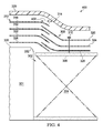
- FIG. 4 an illustration of a cross-sectional view of a forming tool and composite material during forming is depicted in accordance with an illustrative embodiment.
- movement system 304 has lowered plate 306 from the extended position of view 300 in Figure 3 .
- Lowering plate 306 may progressively form plies 312 against edge 332.
- Lowering plate 306 may shorten overlap 315 in Figure 3 to overlap 402.
- Plate 306 is connected to sheets 308 by connection 310. As plate 306 is lowered, sheets 308 may be pulled from between each of plies 312. As sheets 308 are progressively pulled from between each of plies 312, the portions of plies 312 able to move relative to each other decreases.
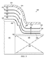
- FIG. 5 an illustration of a cross-sectional view of a forming tool and composite material during forming is depicted in accordance with an illustrative embodiment.
- movement system 304 has lowered plate 306 to a depressed position.
- Sheets 308 have been removed from plies 312 due to lowering plate 306.
- plies 312 may be progressively formed to edge 332.
- FIG. 6 an illustration of a cross-sectional view of a forming tool and composite material during forming is depicted in accordance with an illustrative embodiment.
- movement system 304 has lowered plate 306 to a depressed position.
- Sheets 308 are substantially flat against plate 306.
- plies 312 may be progressively formed to edge 332.
- Plies 312 may have height 602 in view 600.
- FIG. 7 an illustration of a cross-sectional view of a forming tool and composite material during forming is depicted in accordance with an illustrative embodiment.
- plies 312 have been formed to base 302 including edge 332.
- the vacuum pulled under drape 329 may compress plies 312 onto base 302. Further, the vacuum pulled under drape 329 may remove gases from between plies 312.
- height 702 of plies 312 is less than height 602 of plies 312 in Figure 6 .
- plies 312 may be compressed against base 302 to form a substantially wrinkle-free part. Each ply of plies 312 may be compressed against each adjacent ply of plies 312.
- plate 306 may move in a single dimension in Figures 3-7 . This type of motion may be referred to as translational movement. However, in some illustrative examples plate 306 may move in more than one dimension relative to base 302. For example, plate 306 may move in a rotational movement. As one example, plate 306 may pivot about an edge of plate 306 opposite edge 332 of base 302. As another example, plate 306 may pivot about the edge of plate 306 nearest edge 332. Plate 306 may move in any desirable translational or rotational movement such that sheets 308 may be pulled from between each of plies 312 resulting in a composite part of desirable quality.
- plate 306 is described as moving relative to base 302, in some illustrative examples, base 302 may move relative to plate 306. Further, in some illustrative examples base 302 may have rotational movement relative to plate 306. Base 302 may move in any desirable translational or rotational movement such that sheets 308 may be pulled from between each of plies 312 resulting in a composite part of desirable quality.
- Forming tool 800 may be a physical implementation of forming tool 202 of Figure 2 .
- Forming tool 800 may be used to form a cargo floor beam.
- Forming tool 800 may have base 802 with number of cavities 804.
- Number of plates 806 may cover some of number of cavities 804.
- Cavities 808 of number of cavities 804 may be present in base 802 to reduce the weight of forming tool 800.
- Cavities 808 of number of cavities 804 may also advantageously affect the thermal properties of forming tool 800.
- Figure 8 and forming tool 800 not meant to imply physical or architectural limitations to the manner in which an illustrative embodiment may be implemented.
- forming tool 800 is depicted as a tool to form a cargo floor beam, forming tool 800 may have any desirable shape or number of cavities.
- forming tool 800 could be a tool to form a complex structure such as a bulkhead.
- forming tool 800 could be a tool to form an aircraft door.
- View 900 may be a view of forming tool 800 within box 9-9 from direction 9-9(2) of Figure 8 .
- plies 902 of composite material 904 may be present on base 802.
- Plies 902 of composite material 904 may be successively placed on base 802.
- Sheets 906 may be placed over number of plates 806. Plies 902 and portions of sheets 906 may be interleaved on forming tool 800.
- Pins 908 may extend from base 802 through plies 902. Pins 908 may maintain a position of plies 902 relative to base 802 in select locations on forming tool 800. Pins 910 may extend from plates 806 through sheets 906. Pins 910 may maintain a position of sheets 906 relative to plates 806 in select locations.
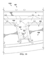
- View 1000 may be a view of forming tool 800 within box 10-10 from direction 10-10(2) of Figure 9 .
- Connectors 1002 may hold sheets 906 on number of plates 806 shown in Figure 8 .
- Connectors 1002 may include first portions inserted through sheets 906 and second portions on top of sheets 906 and connected to the first portions of connectors 1002.
- the first portions of connectors 1002 may be pins 910 of Figure 9 .
- Connectors 1004 may hold plies 902 on forming tool 800.
- Connectors 1004 may include first portions inserted through plies 902 and second portions on top of plies 902.
- the first portions of connectors 1004 may be pins 908 of Figure 9 .
- View 1100 may be a view of forming tool 800 with drape 1102 placed over forming tool 800, plies 902 of composite material 904, and sheets 906.
- View 1100 may be a view of forming tool 800 covered with drape 1102 and with number of plates 806 lowered to a depressed state.
- View 1200 may be a view of forming tool 800 with composite material 904 after forming and removal of drape 1102.
- composite material 904 has been formed into composite structure 1202 having shape 1204.
- Shape 1204 has number of flanges 1206 including flange 1208, flange 1210, flange 1212, flange 1214, flange 1216, and flange 1218.
- Flange 1208 may be created by forming plies 902 to base 802 including forming over edge 1220 of cavity 1222.
- Flange 1210 may be created by forming plies 902 to base 802 including forming over edge 1224 of cavity 1226.
- Flange 1212 may be created by forming plies 902 to base 802 including forming over edge 1228 of cavity 1230.
- Flange 1214 may be created by forming plies 902 to base 802 including forming over edge 1232 of cavity 1234.
- Flange 1216 may be created by forming plies 902 to base 802 including forming over edge 1236 of cavity 1238.
- Flange 1218 may be created by forming plies 902 to base 802 including forming over edge 1240 of cavity 1242.
- connectors 1002 may be removed after forming composite material 904. Pins 908 may still be present through composite structure 1202. Second portions of connectors 1004 may have been removed to facilitate removal of composite structure 1202 from base 802 of forming tool 800.
- View 1300 may be a view of composite structure 1202 from the direction of 13-13 in Figure 12 .
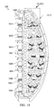
- View 1400 is a view of forming tool 800 with number of plates 806 removed for clarity.
- Number of movement systems 1402 may be positioned within number of cavities 804.
- cavity 1242 may have movement system 1404, movement system 1406, movement system 1408, movement system 1410, movement system 1412, and movement system 1414.
- each of number of movement systems 1402 is a scissor lift.
- at least one of movement systems 1402 may be a movement system other than a scissor lift such as an electrical system, a pneumatic system, or a different type of mechanical system.
- View 1500 may be a view of cavity 1502 of number of cavities 804 within box 14-14 and from direction 14-14(2) of Figure 14 .
- Movement system 1504, movement system 1506, and movement system 1508 of number of movement systems 1402 are present within cavity 1502. Movement system 1504, movement system 1506, and movement system 1508 are each in an extended position. In an extended position, a plate associated with movement system 1504, movement system 1506, and movement system 1508 may be substantially planar with base 802 of forming tool 800.
- Movement system 1504, movement system 1506, and movement system 1508 may be lowered to a depressed position. In lowering each of movement system 1504, movement system 1506, and movement system 1508, a plate associated with each of movement system 1504, movement system 1506, and movement system 1508 may also be lowered. When movement system 1504, movement system 1506, and movement system 1508 are in a depressed position, the plate associated with movement system 1504, movement system 1506, and movement system 1508 may rest on ledge 1510 of cavity 1502.
- Scissor lift 1600 may be a physical implementation of a scissor lift of scissor lifts 252 of Figure 2 .
- Scissor lift 1600 may be a movement system of number of movement systems 1402 of Figure 14 .
- Scissor lift 1600 may be an example of a physical implementation of movement system 304 of Figure 3 .
- Scissor lift 1600 may have spring 1602 biasing scissor lift 1600 in an extended position. By biasing scissor lift 1600 in an extended position, scissor lift 1600 may push a plate against drape 1102 shown in Figure 11 .
- the load for spring 1602 may be selected based on a desired relative surface pressure between plies 902 and sheets 906 shown in Figures 9-11 during forming. In some illustrative examples, the load for spring 1602 may be approximately 2 pounds. A surface pressure between plies 902 and sheets 906 may affect the relative sliding motion between plies 902 in the normal and transversal direction.
- Scissor lift 1600 may have guide 1604 and guide 1606.
- Guide 1604 and guide 1606 may cause the movement of scissor lift 1600 to be smooth. Further, guide 1604 and guide 1606 may limit the height of scissor lift 1600 when extended and the height of scissor lift 1600 when depressed.
- FIG. 17 an illustration of a scissor lift in a depressed position is depicted in accordance with an illustrative embodiment.
- scissor lift 1600 may be in a depressed position.
- plies 204 are depicted as including first ply 268, second ply 270, and third ply 272, plies 204 may include any number of plies. In some illustrative examples, plies 204 includes between 2 and 10 plies. In some illustrative examples, plies 204 may include between 10 and 20 plies. In some illustrative examples, plies 204 may include between 20 and 50 plies.
- plate 306 is shown moving relative to base 302 of forming tool 301 in Figures 3-7 , in some illustrative examples base 302 may move relative to plate 306.
- base 302 may move upward while plate 306 remains stationary.
- plate 306 may move downward while base 302 moves upward.
- plate 306 is shown moving in a single dimension in Figures 3-7 , in some illustrative examples plate 306 may move in more than one dimension relative to base 302. For example, plate 306 may move in a rotational movement. Further, in some illustrative examples base 302 may have rotational movement relative to plate 306.
- Process 1800 may be used to form composite structure 206 of Figure 2 .
- Process 1800 may begin by interleaving a number of composite plies and portions of a number of sheets (operation 1802 ). Portions of the number of sheets may be interleafed with the composite plies in a periphery of an area. In some illustrative examples, the periphery of the area is a portion of the composite plies which will be formed over an edge of a cavity within a forming tool. Portions of the number of sheets may be interleafed with the composite plies.
- Process 1800 may also lower a plate connected to the number of sheets (operation 1804 ). Afterwards, the process terminates. Lowering the plate connected to the number of sheets may pull the portions of the number of sheets from between each of the number of composite plies. Lowering the plate forms the number of sheets against the plate. In some illustrative examples, the plate connected to the number of sheets may be lowered while the number of composite plies and the number of sheets is under vacuum.
- Process 1900 may be used to form composite structure 206 of Figure 2 .
- Process 1900 may begin by placing a first ply onto a base having a number of cavities (operation 1902 ).
- the first ply may be either a thermoplastic composite material or a thermoset composite material.
- Process 1900 may also place a portion of a sheet onto the first ply (operation 1904 ).
- the sheet may be a material selected to reduce friction between the sheet and the first ply.
- the sheet may be a polymeric material.
- the sheet may be polytetrafluoroethylene or polyethylene.
- Process 1900 may then place a second ply onto the first ply (operation 1906 ).
- the second ply may be the same type of composite material as the first ply. However, the second ply may be laid at a different angle than the first ply.
- the first ply may be a 0 degree ply.
- the second ply may be a ply laid at an angle other than 0 degrees.
- Process 1900 may also place a drape over the first ply, the second ply, and the first sheet (operation 1908 ). If subsequent plies and sheets have been placed following the first ply, the second ply, and the first sheet, the drape may also be placed over the subsequent plies and sheets.
- Process 1900 may draw a vacuum under the drape (operation 1910 ).
- Process 1900 may also lower a plate connected to the sheet (operation 1912 ).
- the plate may be lowered as a result of drawing the vacuum under the drape.
- a number of movement systems may be below the plate. Further, the number of movement systems may provide some amount of resistance to downward pressure from the drape. Afterwards, the process terminates.
- each block in the flowcharts or block diagrams may represent at least one of a module, a segment, a function, or a portion of an operation or step.
- the function or functions noted in the blocks may occur out of the order noted in the figures.
- two blocks shown in succession may be executed substantially concurrently, or the blocks may sometimes be performed in the reverse order, depending upon the functionality involved.
- other blocks may be added in addition to the illustrated blocks in a flowchart or block diagram.
- process 1800 may also draw a vacuum on the number of composite plies and the number of sheets.
- process 1800 may also place a drape over the number of composite plies and the number of sheets. Drawing the vacuum on the number of composite plies and the number of sheets may include pulling a vacuum under the drape.
- process 1800 may also place the number of composite plies on a base having a cavity.
- the plate may be associated with the cavity, and lowering the plate connected to the number of sheets may form the number of composite plies to the base.
- forming the number of composite plies to the base includes forming a portion of the number of composite plies to the base within the cavity.
- process 1800 may also heat the composite plies to a forming temperature prior to lowering the plate.
- the composite plies may be a thermoplastic material.
- lowering the plate connected to the sheet may pull the portion of the sheet from between the first ply and the second ply. In some illustrative examples, in process 1900, lowering the plate may form the sheet against the plate. In some illustrative examples, in process 1900, lowering the plate connected to the number of sheets may form the first ply and the second ply to the base. In these illustrative examples, forming the first ply and the second ply to the base may include forming a portion of the first ply and a portion of the second ply to the base within the cavity. In some illustrative examples, process 1900 may also heat the first ply and the second ply to a forming temperature prior to lowering the plate.
- aircraft manufacturing and service method 2000 may be described in the context of aircraft manufacturing and service method 2000 as shown in Figure 20 and aircraft 2100 as shown in Figure 21 .
- Figure 20 an illustration of a block diagram of an aircraft manufacturing and service method is depicted in accordance with an illustrative embodiment.
- aircraft manufacturing and service method 2000 may include specification and design 2002 of aircraft 2100 in Figure 21 and material procurement 2004.
- aircraft 2100 in Figure 21 During production, component and subassembly manufacturing 2006 and system integration 2008 of aircraft 2100 in Figure 21 takes place. Thereafter, aircraft 2100 in Figure 21 may go through certification and delivery 2010 in order to be placed in service 2012. While in service 2012 by a customer, aircraft 2100 in Figure 21 is scheduled for routine maintenance and service 2014, which may include modification, reconfiguration, refurbishment, and other maintenance or service.
- Each of the processes of aircraft manufacturing and service method 2000 may be performed or carried out by a system integrator, a third party, and/or an operator.
- the operator may be a customer.
- a system integrator may include, without limitation, any number of aircraft manufacturers and major-system subcontractors
- a third party may include, without limitation, any number of vendors, subcontractors, and suppliers
- an operator may be an airline, a leasing company, a military entity, a service organization, and so on.
- aircraft 2100 is produced by aircraft manufacturing and service method 2000 in Figure 20 and may include airframe 2102 with plurality of systems 2104 and interior 2106.
- systems 2104 include one or more of propulsion system 2108, electrical system 2110, hydraulic system 2112, and environmental system 2114. Any number of other systems may be included.
- propulsion system 2108 includes one or more of propulsion system 2108, electrical system 2110, hydraulic system 2112, and environmental system 2114. Any number of other systems may be included.
- an aerospace example is shown, different illustrative embodiments may be applied to other industries, such as the automotive industry.
- the apparatuses and methods embodied herein may be employed during at least one of the stages of aircraft manufacturing and service method 2000 in Figure 20 .
- One or more illustrative embodiments may be used during component and subassembly manufacturing 2006.
- forming tool 202 may be used to form composite structure 206 during component and subassembly manufacturing 2006.
- composite structure 206 formed using forming tool 202 may also be used to replace a composite structure during maintenance and service 2014.
- the illustrative embodiments provide a method and apparatus for progressively forming composite material.
- the method and apparatus may produce a composite structure by progressively forming each ply individually. A periphery of each ply to be formed may only touch other adjacent plies after the periphery has been formed.
- a sheet Prior to forming a periphery of a ply, a sheet may separate the periphery of the ply from an adjacent ply.
- the sheet may be formed of a material selected to reduce the friction between the sheet and the ply.
- An apparatus may comprise a base, a plate, a number of movement systems, and a number of sheets.
- the base may have a number of cavities.
- the plate may be associated with a cavity of the number of cavities.
- the number of movement systems may be within the cavity of the number of cavities.
- the number of sheets may be connected to the plate.
- a vacuum may be drawn on a number of composite plies on the apparatus and the number of sheets.
- the plate connected to the number of sheets may be lowered while the number of composite plies and the number of sheets is under the vacuum.
- the number of sheets may be progressively pulled from between the number of composite plies.
- the number of composite plies may be formed against the tool.
- the composite plies may be formed on an edge of a cavity of the tool.
- Features such as bends, holes, flanges, or other desirable features may be formed into the composite plies to form a composite structure.
- the composite structure may have a desirable quality.
- the composite structure may be substantially free of wrinkles.
- forming composite structure 206 using forming tool 202 including number of sheets 222 and number of plates 220 at least one of manufacturing time and manufacturing cost may be reduced.
- rework and discard rates may be reduced.
- manufacturing cost may be reduced.
- a composite forming apparatus comprising:
- the number of sheets are formed of a polymeric material.
- the base has a number of cavities, and wherein the plate is associated with a cavity of the number of cavities.
- the number of movement systems are within the cavity of the number of cavities.
- the plate is depressible and associated with the number of movement systems.
- the composite forming apparatus further comprises a drape.
- the composite forming apparatus further comprises a vacuum source associated with at least one of the drape or the base.
- An apparatus comprising:
- the plate is associated with the number of movement systems.
- the number of sheets are formed of a polymeric material.
- each of the number of sheets has substantially the same cross-sectional area as the plate.
- the number of movement systems is a number of scissor lifts.
- the apparatus further comprises:
- a method comprising:
- the method further comprises:
- lowering the plate connected to the number of sheets is performed while the number of composite plies and the number of sheets is under the vacuum.
- the method further comprises:
- lowering the plate connected to the number of sheets pulls the portions of the number of sheets from between each of the number of composite plies.
- lowering the plate forms the number of sheets against the plate.
- the method further comprises:
- forming the number of composite plies to the base includes forming a portion of the number of composite plies to the base within the cavity.
- the method further comprises:
- a method comprising:
- lowering the plate connected to the first sheet pulls the portion of the first sheet from between the first ply and the second ply.
- lowering the plate forms the first sheet against the plate.
- lowering the plate connected to the first sheet forms the first ply and the second ply to the base.
- forming the first ply and the second ply to the base includes forming a portion of the first ply and a portion of the second ply to the base within the cavity.
- the method further comprises:
Landscapes
- Chemical & Material Sciences (AREA)
- Engineering & Computer Science (AREA)
- Composite Materials (AREA)
- Mechanical Engineering (AREA)
- Moulding By Coating Moulds (AREA)
- Casting Or Compression Moulding Of Plastics Or The Like (AREA)
Abstract
Description
- The present disclosure generally relates to composite structures and, in particular, to the fabrication of composite structures. Still more particularly, the present disclosure relates to a method and apparatus for progressively forming composite structures.
- Aircraft are being designed and manufactured with greater and greater percentages of composite materials. Composite materials are used in aircraft to decrease the weight of the aircraft. This decreased weight improves performance features such as payload capacities and fuel efficiencies. Further, composite materials may provide longer service life for various components in an aircraft.
- Composite materials are tough, lightweight materials created by combining two or more functional components. For example, a composite material may include reinforcing fibers bound in polymer resin matrix. The fibers may be randomly distributed chopped fibers, unidirectional, or may take the form of a woven cloth or fabric.
- In thermoset composites, fibers and resins are arranged and cured to form a composite structure. In thermoplastic composites, fibers and resins are heated to provide formability. While formable, the thermoplastic composite may be shaped and then allowed to cool.
- To form composite structures with complex shapes, multiple plies of composite material may be placed on top of each other over a tool. The plies of composite material may be formed over the tool including over at least one tool radius. Forming the plies of composite material may form inconsistencies outside of tolerance. When the inconsistencies are outside of tolerance the composite structure may have undesirable quality. When the composite structure has undesirable quality, the composite structure may be reworked or discarded. Reworking a composite structure or discarding a composite structure may increase at least one of manufacturing time or manufacturing cost.
- Therefore, it would be desirable to have a method and apparatus that take into account at least some of the issues discussed above, as well as other possible issues. Specifically, one issue is to find a method and apparatus for forming composite materials that may result in a composite structure having a complex shape and a desirable quality. Further, another issue is to find a method and apparatus for forming multiple plies of composite materials over at least one tooling radius.
- An illustrative embodiment of the present disclosure provides an apparatus. The apparatus comprises a base, a plate, a number of movement systems, and a number of sheets. The number of movement systems move one of the base and the plate relative to the other. The number of sheets is connected to the plate.
- Another illustrative embodiment of the present disclosure provides an apparatus. The apparatus comprises a base, a plate, a number of movement systems, and a number of sheets. The base may have a number of cavities. The plate may be associated with a cavity of the number of cavities. The number of movement systems may be within the cavity of the number of cavities. The number of sheets may be connected to the plate.
- A further illustrative embodiment of the present disclosure provides a method. The method may comprise interleaving a number of composite plies and portions of a number of sheets. The method may also lower a plate connected to the number of sheets.
- Another illustrative embodiment of the present disclosure provides a method. The method may comprise placing a first ply onto a base having a number of cavities. The method may also place a portion of a sheet onto the first ply. The method may further place a second ply onto the first ply. The method may further place a drape over the first ply, the second ply, and the first sheet. The method may also draw a vacuum under the drape. The method may further lower a plate connected to the sheet.
- The features and functions can be achieved independently in various embodiments of the present disclosure or may be combined in yet other embodiments in which further details can be seen with reference to the following description and drawings.
- The novel features believed characteristic of the illustrative embodiments are set forth in the appended claims. The illustrative embodiments, however, as well as a preferred mode of use, further objectives and features thereof, will best be understood by reference to the following detailed description of an illustrative embodiment of the present disclosure when read in conjunction with the accompanying drawings, wherein:
-
Figure 1 is an illustration of an aircraft in which an illustrative embodiment may be implemented; -
Figure 2 is an illustration of a block diagram of a manufacturing environment in accordance with an illustrative embodiment; -
Figure 3 is an illustration of a cross-sectional view of a forming tool and composite material during forming in accordance with an illustrative embodiment; -
Figure 4 is an illustration of a cross-sectional view of a forming tool and composite material during forming in accordance with an illustrative embodiment; -
Figure 5 is an illustration of a cross-sectional view of a forming tool and composite material during forming in accordance with an illustrative embodiment; -
Figure 6 is an illustration of a cross-sectional view of a forming tool and composite material during forming in accordance with an illustrative embodiment; -
Figure 7 is an illustration of a cross-sectional view of a forming tool and composite material during forming in accordance with an illustrative embodiment; -
Figure 8 is an illustration of an isometric view of a forming tool in accordance with an illustrative embodiment; -
Figure 9 is an illustration of a portion of a forming tool and composite material in accordance with an illustrative embodiment; -
Figure 10 is an illustration of a portion of a forming tool and composite material in accordance with an illustrative embodiment; -
Figure 11 is an illustration of a forming tool during forming in accordance with an illustrative embodiment; -
Figure 12 is an illustration of a composite material on a forming tool after forming in accordance with an illustrative embodiment; -
Figure 13 is an illustration of a composite structure formed on a forming tool in accordance with an illustrative embodiment; -
Figure 14 is an illustration of a forming tool with a number of movement systems within a number of cavities in accordance with an illustrative embodiment; -
Figure 15 is an illustration of a number of movement systems within a cavity of a forming tool in accordance with an illustrative embodiment; -
Figure 16 is an illustration of a scissor lift in an extended position in accordance with an illustrative embodiment; -
Figure 17 is an illustration of a scissor lift in a depressed position in accordance with an illustrative embodiment; -
Figure 18 is an illustration of a flowchart of a process for forming a composite structure in accordance with an illustrative embodiment; -
Figure 19 is an illustration of a flowchart of a process for forming a composite structure in accordance with an illustrative embodiment; -
Figure 20 is an illustration of an aircraft manufacturing and service method in the form of a block diagram in accordance with an illustrative embodiment; and -
Figure 21 is an illustration of an aircraft in the form of a block diagram in which an illustrative embodiment may be implemented. - The illustrative embodiments recognize and take into account one or more different considerations. The illustrative embodiments recognize and take into account that a composite structure may be formed from at least one of a thermoplastic material or a thermoset material. The illustrative embodiments recognize and take into account that a first composite structure may be initially formed from a first composite material. Subsequent composite structures having substantially the same shape as the first composite structure may be formed from a different composite material. Thus, the illustrative embodiments recognize and take into account that a tool may desirably be usable with different types of composite materials.
- The illustrative embodiments recognize and take into account that it may be desirable to form a substantially flat multiple ply composite material into a complex shape without out of tolerance inconsistencies. The illustrative embodiments recognize and take into account that a substantially flat multiple ply composite material may be formed into a complex shape by forming the plies over a tool radius. The illustrative embodiments recognize and take into account that forming plies of composite material over a tool radius may result in unexpected ply shifts, tearing, splitting, or other undesirable inconsistencies. The illustrative embodiments recognize and take into account that to decrease inconsistencies in a composite structure, plies of composite material may be darted. Darts of a composite material may be portions of the composite material separated by spaces. The darts of the composite material may be folded over a tool radius until they touch. Darting a composite material may add an undesirable amount of manufacturing time. Further, forming a darted composite material may still result in undesirable inconsistencies. Yet further, darting a composite material may still produce a composite structure of undesirable quality.
- The illustrative embodiments recognize and take into account that composite plies may stick to each other during forming causing inconsistencies. Sticking may be undesirable when it is desired for the plies to slip relative to each other. Ply slippage may be desired when plies are being formed such that an outer ply may have a longer distance to travel than an inner ply. For example, ply slippage may be desired around a bend or radius. Without ply slippage relative to each other, each ply may move the same distance or length of travel and wrinkles may result. Plies sticking to each other during forming may cause wrinkles, tearing, or other inconsistencies. These inconsistencies may be out of tolerance, which may cause the composite structure to have undesirable quality.
- Thus, the illustrative embodiments present methods and an apparatus to form a composite structure. The apparatus comprises a base, a plate, a number of movement systems, and a number of sheets. The base may have a number of cavities. The plate may be associated with a cavity of the number of cavities. The number of movement systems may be within the cavity of the number of cavities. The number of sheets may be connected to the plate.
- With reference now to the figures, and in particular, with reference to
Figure 1 , an illustration of an aircraft is depicted in which an illustrative embodiment may be implemented. In this illustrative example,aircraft 100 haswing 102 andwing 104 attached tobody 106.Aircraft 100 includesengine 108 attached towing 102 andengine 110 attached towing 104. -
Body 106 hastail section 112.Horizontal stabilizer 114,horizontal stabilizer 116, andvertical stabilizer 118 are attached totail section 112 ofbody 106. -
Aircraft 100 is an example of an aircraft in which a composite structure may be implemented in accordance with an illustrative embodiment. For example, a composite structure may be used in support structures ofaircraft 100. For example, a composite structure may be used in at least one of a beam, a rib, or other desirable support structure in at least one ofwing 102,wing 104, orbody 106.Aircraft 100 may be a physical implementation ofaircraft 2100 ofFigure 21 . - This illustration of
aircraft 100 is provided for purposes of illustrating one environment in which the different illustrative embodiments may be implemented. The illustration ofaircraft 100 inFigure 1 is not meant to imply architectural limitations as to the manner in which different illustrative embodiments may be implemented. For example,aircraft 100 is shown as a commercial passenger aircraft. The different illustrative embodiments may be applied to other types of aircraft, such as a private passenger aircraft, a rotorcraft, and other suitable types of aircraft. - Turning now to
Figure 2 , an illustration of a block diagram of a manufacturing environment is depicted in accordance with an illustrative embodiment.Manufacturing environment 200 may be used to form a composite structure. In some illustrative examples,manufacturing environment 200 may be used to form a composite structure ofaircraft 100 ofFigure 1 .Manufacturing environment 200 may include formingtool 202, plies 204,composite structure 206,drape 208,heating equipment 210, andvacuum source 212. - Forming
tool 202 may be used to formplies 204 intocomposite structure 206. Formingtool 202 may include base 214 having number ofcavities 216.Base 214 may be formed of a material selected based on at least one of thermal characteristics, machinability, material cost, material weight, material reactivity, material durability, or other material properties. In some illustrative examples,base 214 may be formed of at least one of a polymeric material, a metal, an alloy, a wood, a ceramic, or other desirable material. - Number of
movement systems 218 may be associated with number ofplates 220 within number ofcavities 216 inbase 214. In some illustrative examples, number ofplates 220 may be formed of the same material asbase 214. In other illustrative examples, number ofplates 220 may be formed of a different material thanbase 214. During forming ofplies 204 intocomposite structure 206, number ofplates 220 may lower intocavities 216. As a result, number ofplates 220 may also be referred to as a number of depressible plates. - Number of
sheets 222 may be connected to number ofplates 220 using number ofconnections 224. Each of number ofsheets 222 has substantially the same cross-sectional area as the respective plate of number ofplates 220 to which it is connected. If number ofsheets 222 is connected to a single plate, each of number ofsheets 222 has substantially the same cross-sectional area as the plate. - Forming
tool 202 may haveshape 226. In some illustrative examples,shape 226 may be a complementary shape to shape 228 ofcomposite structure 206. Complementary shapes may be shapes that fit together. In some illustrative examples, a portion ofshape 226 may be substantially the same asshape 228 ofcomposite structure 206. - Shape 228 of
composite structure 206 may include at least one of number offlanges 230, number ofholes 232, andthickness 234. Shape 228 ofcomposite structure 206 may be described as a complex shape. A complex shape may combine parts or all of simple shapes. Complex shapes in composite materials may include constant curvatures, non-constant curvatures, bends, angles, or other non-planar features such as number offlanges 230. A skin of an aircraft wing may be an example of a complex shape. Number offlanges 230 may be a number of projections from the remainder ofcomposite structure 206. Number offlanges 230 may have an angle relative to the remainder ofcomposite structure 206. The angle may range from greater than about 0 degrees to less than about 180 degrees. In some illustrative examples, number offlanges 230 may be at an angle about 90 degrees from the remainder ofcomposite structure 206. Number offlanges 230 may causeshape 228 ofcomposite structure 206 to be a non-planar shape. Shape 228 ofcomposite structure 206 may be formed intoplies 204 by formingplies 204 againstbase 214. - Number of
cavities 216 of formingtool 202 may includefirst cavity 236 andsecond cavity 238.First cavity 236 may haveedge 240. In some illustrative examples, plies 204 may be formed against at least a portion ofedge 240 offirst cavity 236.Second cavity 238 may haveedge 242. In some illustrative examples, plies 204 may be formed against at least a portion ofedge 242 ofsecond cavity 238. - Number of
plates 220 may be lowered to formplies 204 against at least a portion of at least one ofedge 240 oredge 242.First plate 243 may be associated withfirst cavity 236.Second plate 244 may be associated withsecond cavity 238.First plate 243 may be lowered to formplies 204 against at least a portion ofedge 240.Second plate 244 may be lowered to formplies 204 against at least a portion ofedge 242. - Number of
movement systems 218 may be used to lower number ofplates 220. Number ofmovement systems 218 may include at least one ofmechanical systems 246,electrical systems 248, or pneumatic systems 250. In some illustrative examples, number ofmovement system 218 may move number ofplates 220 by inflating or deflating using pneumatic systems 250. In some illustrative examples,mechanical systems 246 may be scissor lifts 252. In these illustrative examples, number ofmovement systems 218 may be a number of scissor lifts. - In some illustrative examples,
first movement system 254 andsecond movement system 256 of number ofmovement systems 218 may be associated withfirst plate 243. In some illustrative examples,first movement system 254 of number ofmovement systems 218 may be associated withfirst plate 243 whilesecond movement system 256 may be associated withsecond plate 244. - Number of
sheets 222 may be formed of a material selected to allowplies 204 to slip relative to each other. The material of number ofsheets 222 may be selected based on at least one of material reactivity, material durability, coefficient of friction, thermal properties, or some other desirable material characteristic. In some illustrative examples, number ofsheets 222 may bepolymeric material 257.Polymeric material 257 may bepolytetrafluoroethylene 258,polyethylene 259, or another desirable polymeric material. Number ofsheets 222 may includefirst sheet 260,second sheet 262,third sheet 264, andfourth sheet 266.First sheet 260 andsecond sheet 262 may be connected tofirst plate 243.First sheet 260 andsecond sheet 262 may be pulled downward intofirst cavity 236 asfirst plate 243 is lowered.Third sheet 264 andfourth sheet 266 may be connected tosecond plate 244.Third sheet 264 andfourth sheet 266 may be pulled downward intosecond cavity 238 assecond plate 244 is lowered. - A portion of
first sheet 260 may be positioned betweenfirst ply 268 andsecond ply 270. A portion ofsecond sheet 262 may be positioned betweensecond ply 270 andthird ply 272. The portion offirst sheet 260 may be positioned betweenfirst ply 268 andsecond ply 270 inperiphery 274 ofarea 276. The portion ofsecond sheet 262 may be positioned betweensecond ply 270 andthird ply 272 inperiphery 274 ofarea 276. - A portion of
third sheet 264 may be positioned betweenfirst ply 268 andsecond ply 270. The portion ofthird sheet 264 may be positioned betweenfirst ply 268 andsecond ply 270 inperiphery 278 ofarea 280. A portion offourth sheet 266 may be positioned betweensecond ply 270 andthird ply 272. The portion offourth sheet 266 may be positioned betweensecond ply 270 andthird ply 272 inperiphery 278 ofarea 280. - Number of
areas 282 may includearea 276 andarea 280. Number ofareas 282 may be areas which include number ofholes 232. Number ofareas 282 may include number offlanges 230. Number offlanges 230 may be located in at least one ofperiphery 274 andperiphery 278. - To form
composite structure 206 fromplies 204, plies 204 may be placed ontobase 214. Number ofsheets 222 may be interleaved with portions ofplies 204.Drape 208 may be placed overplies 204 and number ofsheets 222. A vacuum may be pulled underdrape 208 usingvacuum source 212. As a vacuum is pulled onplies 204 underdrape 208, number ofplates 220 may be lowered. As number ofplates 220 are lowered,first ply 268,second ply 270, andthird ply 272 may be progressively formed to edge 240 andedge 242. As number ofplates 220 are lowered,first sheet 260,second sheet 262,third sheet 264, andfourth sheet 266 may be progressively removed from betweenplies 204. - In some illustrative examples, the act of pulling the vacuum under
drape 208 moves number ofplates 220 downward. In these illustrative examples, the biasing force of number ofmovement systems 218 towardsdrape 208 may be less than the downward force produced by pulling a vacuum underdrape 208. In some of these illustrative examples, number ofmovement systems 218 may be scissor lifts 252.Scissor lifts 252 may be biased to an extended position. In some illustrative examples, at least one spring may bias a scissor lift ofscissor lifts 252 to an extended position. -
Plies 204 may be formed ofcomposite material 284.Plies 204 may also be referred to as composite plies.Composite material 284 may bethermoplastic material 286 orthermoset material 288. Whencomposite material 284 isthermoset material 288, plies 204 may be formed without adding heat. Whencomposite material 284 isthermoplastic material 286, plies 204 may be heated byheating equipment 210. By applying heat toplies 204,thermoplastic material 286 may have increased formability. By applying heat toplies 204,thermoplastic material 286 may be formed againstbase 214. - This illustration of
manufacturing environment 200 is provided for purposes of illustrating one environment in which the different illustrative embodiments may be implemented. The illustration ofmanufacturing environment 200 inFigure 2 is not meant to imply architectural limitations as to the manner in which different illustrative embodiments may be implemented. For example, number ofmovement systems 218 may be associated with formingtool 202. In some illustrative examples, formingtool 202 may move relative to number ofplates 220. In some illustrative examples, formingtool 202 may move upward while number ofplates 220 remains stationary. In some illustrativeexamples forming tool 202 may move upward while number ofplates 220 moves downward. - As another illustrative example,
manufacturing environment 200 may also include a pressure source. For example, a pressure source may apply pressure to drape 208 during forming ofcomposite material 284. - Turning now to
Figure 3 , an illustration of a cross-sectional view of a forming tool and composite material during forming is depicted in accordance with an illustrative embodiment. View 300 is a cross-sectional view of formingtool 301. Formingtool 301 may be a physical implementation of formingtool 202 inFigure 2 . Formingtool 301 includesbase 302,cavity 303, andmovement system 304 within cavity.Plate 306 is associated withmovement system 304.Plate 306 may also be referred to as a depressible plate. As depicted inview 300,plate 306 may be in an extended position. Number ofsheets 308 is connected to plate 306 byconnection 310. Number ofsheets 308 and plies 312 are interleaved inperiphery 314. Number ofsheets 308 and plies 312 haveoverlap 315. - First ply 316 and
second ply 318 may move relative to each other inperiphery 314.First sheet 320 may allowfirst ply 316 andsecond ply 318 to move relative to each other inperiphery 314. -
Second ply 318 andthird ply 322 may move relative to each other inperiphery 314.Second sheet 324 may allowsecond ply 318 andthird ply 322 to move relative to each other inperiphery 314. -
Third ply 322 andfourth ply 326 may move relative to each other inperiphery 314.Third sheet 328 may allowthird ply 322 andfourth ply 326 to move relative to each other inperiphery 314. -
Drape 329 may be positioned overplies 312 and number ofsheets 308. After positioningdrape 329, a vacuum may be pulled underdrape 329. In this illustrative example,movement system 304 may holdplate 306 substantially parallel to surface 330 ofbase 302 of formingtool 301.Plate 306 may be in an extended position. To progressively form plies 312 againstedge 332,plate 306 may be moved downward. - Turning now to
Figure 4 , an illustration of a cross-sectional view of a forming tool and composite material during forming is depicted in accordance with an illustrative embodiment. Inview 400,movement system 304 has loweredplate 306 from the extended position ofview 300 inFigure 3 . Loweringplate 306 may progressively form plies 312 againstedge 332. Loweringplate 306 may shortenoverlap 315 inFigure 3 to overlap 402.Plate 306 is connected tosheets 308 byconnection 310. Asplate 306 is lowered,sheets 308 may be pulled from between each ofplies 312. Assheets 308 are progressively pulled from between each ofplies 312, the portions ofplies 312 able to move relative to each other decreases. - Turning now to
Figure 5 , an illustration of a cross-sectional view of a forming tool and composite material during forming is depicted in accordance with an illustrative embodiment. Inview 500,movement system 304 has loweredplate 306 to a depressed position.Sheets 308 have been removed fromplies 312 due to loweringplate 306. As depicted, plies 312 may be progressively formed to edge 332. - Turning now to
Figure 6 , an illustration of a cross-sectional view of a forming tool and composite material during forming is depicted in accordance with an illustrative embodiment. Inview 600,movement system 304 has loweredplate 306 to a depressed position.Sheets 308 are substantially flat againstplate 306. As depicted, plies 312 may be progressively formed to edge 332.Plies 312 may haveheight 602 inview 600. - Turning now to
Figure 7 , an illustration of a cross-sectional view of a forming tool and composite material during forming is depicted in accordance with an illustrative embodiment. Inview 700, plies 312 have been formed tobase 302 includingedge 332. The vacuum pulled underdrape 329 may compressplies 312 ontobase 302. Further, the vacuum pulled underdrape 329 may remove gases from betweenplies 312. As can be seen inview 700,height 702 ofplies 312 is less thanheight 602 ofplies 312 inFigure 6 . As can be seen inview 700, plies 312 may be compressed againstbase 302 to form a substantially wrinkle-free part. Each ply ofplies 312 may be compressed against each adjacent ply ofplies 312. - As depicted,
plate 306 may move in a single dimension inFigures 3-7 . This type of motion may be referred to as translational movement. However, in someillustrative examples plate 306 may move in more than one dimension relative tobase 302. For example,plate 306 may move in a rotational movement. As one example,plate 306 may pivot about an edge ofplate 306opposite edge 332 ofbase 302. As another example,plate 306 may pivot about the edge ofplate 306nearest edge 332.Plate 306 may move in any desirable translational or rotational movement such thatsheets 308 may be pulled from between each ofplies 312 resulting in a composite part of desirable quality. - Further, although
plate 306 is described as moving relative tobase 302, in some illustrative examples,base 302 may move relative toplate 306. Further, in some illustrative examples base 302 may have rotational movement relative toplate 306.Base 302 may move in any desirable translational or rotational movement such thatsheets 308 may be pulled from between each ofplies 312 resulting in a composite part of desirable quality. - Turning now to
Figure 8 , an illustration of an isometric view of a forming tool is depicted in accordance with an illustrative embodiment. Formingtool 800 may be a physical implementation of formingtool 202 ofFigure 2 . Formingtool 800 may be used to form a cargo floor beam. Formingtool 800 may have base 802 with number ofcavities 804. Number ofplates 806 may cover some of number ofcavities 804.Cavities 808 of number ofcavities 804 may be present inbase 802 to reduce the weight of formingtool 800.Cavities 808 of number ofcavities 804 may also advantageously affect the thermal properties of formingtool 800. -
Figure 8 and formingtool 800 not meant to imply physical or architectural limitations to the manner in which an illustrative embodiment may be implemented. Although formingtool 800 is depicted as a tool to form a cargo floor beam, formingtool 800 may have any desirable shape or number of cavities. For example, formingtool 800 could be a tool to form a complex structure such as a bulkhead. As another example, formingtool 800 could be a tool to form an aircraft door. - Turning now to
Figure 9 , an illustration of a portion of a forming tool and composite material is depicted in accordance with an illustrative embodiment. View 900 may be a view of formingtool 800 within box 9-9 from direction 9-9(2) ofFigure 8 . Inview 900, plies 902 ofcomposite material 904 may be present onbase 802.Plies 902 ofcomposite material 904 may be successively placed onbase 802.Sheets 906 may be placed over number ofplates 806.Plies 902 and portions ofsheets 906 may be interleaved on formingtool 800. -
Pins 908 may extend frombase 802 throughplies 902.Pins 908 may maintain a position ofplies 902 relative tobase 802 in select locations on formingtool 800.Pins 910 may extend fromplates 806 throughsheets 906.Pins 910 may maintain a position ofsheets 906 relative toplates 806 in select locations. - Turning now to
Figure 10 , an illustration of a portion of a forming tool and composite material is depicted in accordance with an illustrative embodiment.View 1000 may be a view of formingtool 800 within box 10-10 from direction 10-10(2) ofFigure 9 .Connectors 1002 may holdsheets 906 on number ofplates 806 shown inFigure 8 .Connectors 1002 may include first portions inserted throughsheets 906 and second portions on top ofsheets 906 and connected to the first portions ofconnectors 1002. The first portions ofconnectors 1002 may bepins 910 ofFigure 9 .Connectors 1004 may holdplies 902 on formingtool 800.Connectors 1004 may include first portions inserted throughplies 902 and second portions on top ofplies 902. The first portions ofconnectors 1004 may bepins 908 ofFigure 9 . - Turning now to
Figure 11 , an illustration of a forming tool during forming is depicted in accordance with an illustrative embodiment.View 1100 may be a view of formingtool 800 withdrape 1102 placed over formingtool 800, plies 902 ofcomposite material 904, andsheets 906.View 1100 may be a view of formingtool 800 covered withdrape 1102 and with number ofplates 806 lowered to a depressed state. - Turning now to
Figure 12 , an illustration of a composite material on a forming tool after forming is depicted in accordance with an illustrative embodiment.View 1200 may be a view of formingtool 800 withcomposite material 904 after forming and removal ofdrape 1102. In this illustrative example,composite material 904 has been formed intocomposite structure 1202 havingshape 1204.Shape 1204 has number offlanges 1206 includingflange 1208,flange 1210,flange 1212,flange 1214,flange 1216, andflange 1218.Flange 1208 may be created by formingplies 902 tobase 802 including forming overedge 1220 ofcavity 1222.Flange 1210 may be created by formingplies 902 tobase 802 including forming overedge 1224 ofcavity 1226.Flange 1212 may be created by formingplies 902 tobase 802 including forming overedge 1228 ofcavity 1230.Flange 1214 may be created by formingplies 902 tobase 802 including forming overedge 1232 ofcavity 1234.Flange 1216 may be created by formingplies 902 tobase 802 including forming overedge 1236 ofcavity 1238.Flange 1218 may be created by formingplies 902 tobase 802 including forming overedge 1240 ofcavity 1242. - As can be seen from
view 1200,connectors 1002 may be removed after formingcomposite material 904.Pins 908 may still be present throughcomposite structure 1202. Second portions ofconnectors 1004 may have been removed to facilitate removal ofcomposite structure 1202 frombase 802 of formingtool 800. - Turning now to
Figure 13 , an illustration of a composite structure formed on a forming tool is depicted in accordance with an illustrative embodiment.View 1300 may be a view ofcomposite structure 1202 from the direction of 13-13 inFigure 12 . - Turning now to
Figure 14 , an illustration of a forming tool with a number of movement systems within a number of cavities is depicted in accordance with an illustrative embodiment.View 1400 is a view of formingtool 800 with number ofplates 806 removed for clarity. Number ofmovement systems 1402 may be positioned within number ofcavities 804. In this illustrative example,cavity 1242 may havemovement system 1404,movement system 1406,movement system 1408,movement system 1410,movement system 1412, andmovement system 1414. In this illustrative example, each of number ofmovement systems 1402 is a scissor lift. In some illustrative examples, at least one ofmovement systems 1402 may be a movement system other than a scissor lift such as an electrical system, a pneumatic system, or a different type of mechanical system. - Turning now to
Figure 15 , an illustration of a number of movement systems within a cavity of a forming tool is depicted in accordance with an illustrative embodiment.View 1500 may be a view ofcavity 1502 of number ofcavities 804 within box 14-14 and from direction 14-14(2) ofFigure 14 . -
Movement system 1504,movement system 1506, andmovement system 1508 of number ofmovement systems 1402 are present withincavity 1502.Movement system 1504,movement system 1506, andmovement system 1508 are each in an extended position. In an extended position, a plate associated withmovement system 1504,movement system 1506, andmovement system 1508 may be substantially planar withbase 802 of formingtool 800. -
Movement system 1504,movement system 1506, andmovement system 1508 may be lowered to a depressed position. In lowering each ofmovement system 1504,movement system 1506, andmovement system 1508, a plate associated with each ofmovement system 1504,movement system 1506, andmovement system 1508 may also be lowered. Whenmovement system 1504,movement system 1506, andmovement system 1508 are in a depressed position, the plate associated withmovement system 1504,movement system 1506, andmovement system 1508 may rest onledge 1510 ofcavity 1502. - Turning now to
Figure 16 , an illustration of a scissor lift in an extended position is depicted in accordance with an illustrative embodiment.Scissor lift 1600 may be a physical implementation of a scissor lift ofscissor lifts 252 ofFigure 2 .Scissor lift 1600 may be a movement system of number ofmovement systems 1402 ofFigure 14 .Scissor lift 1600 may be an example of a physical implementation ofmovement system 304 ofFigure 3 . -
Scissor lift 1600 may havespring 1602biasing scissor lift 1600 in an extended position. By biasingscissor lift 1600 in an extended position,scissor lift 1600 may push a plate againstdrape 1102 shown inFigure 11 . The load forspring 1602 may be selected based on a desired relative surface pressure betweenplies 902 andsheets 906 shown inFigures 9-11 during forming. In some illustrative examples, the load forspring 1602 may be approximately 2 pounds. A surface pressure betweenplies 902 andsheets 906 may affect the relative sliding motion betweenplies 902 in the normal and transversal direction. -
Scissor lift 1600 may haveguide 1604 andguide 1606.Guide 1604 and guide 1606 may cause the movement ofscissor lift 1600 to be smooth. Further,guide 1604 and guide 1606 may limit the height ofscissor lift 1600 when extended and the height ofscissor lift 1600 when depressed. - Turning now to
Figure 17 , an illustration of a scissor lift in a depressed position is depicted in accordance with an illustrative embodiment. Inview 1700,scissor lift 1600 may be in a depressed position. - The illustration of
aircraft 100 inFigure 1 ,manufacturing environment 200 inFigure 2 , forming tool depictions inFigures 3-12 and 14-15, movement systems inFigure 16-17 , and composite structure inFigure 13 are not meant to imply physical or architectural limitations to the manner in which an illustrative embodiment may be implemented. Other components in addition to or in place of the ones illustrated may be used. Some components may be unnecessary. Also, the blocks are presented to illustrate some functional components. One or more of these blocks may be combined, divided, or combined and divided into different blocks when implemented in an illustrative embodiment. - For example, although
plies 204 are depicted as includingfirst ply 268,second ply 270, andthird ply 272, plies 204 may include any number of plies. In some illustrative examples, plies 204 includes between 2 and 10 plies. In some illustrative examples, plies 204 may include between 10 and 20 plies. In some illustrative examples, plies 204 may include between 20 and 50 plies. - As another example, although
plate 306 is shown moving relative to base 302 of formingtool 301 inFigures 3-7 , in some illustrative examples base 302 may move relative toplate 306. For example,base 302 may move upward whileplate 306 remains stationary. In other illustrative examples,plate 306 may move downward whilebase 302 moves upward. - As yet another example, although
plate 306 is shown moving in a single dimension inFigures 3-7 , in someillustrative examples plate 306 may move in more than one dimension relative tobase 302. For example,plate 306 may move in a rotational movement. Further, in some illustrative examples base 302 may have rotational movement relative toplate 306. - The different components shown in
Figures 1 and3 -17 may be combined with components inFigure 2 , used with components inFigure 2 , or a combination of the two. Additionally, some of the components inFigures 1 and3- 17 may be illustrative examples of how components shown in block form inFigure 2 may be implemented as physical structures. - Turning now to
Figure 18 , an illustration of a flowchart of a process for forming a composite structure is depicted in accordance with an illustrative embodiment.Process 1800 may be used to formcomposite structure 206 ofFigure 2 .Process 1800 may begin by interleaving a number of composite plies and portions of a number of sheets (operation 1802). Portions of the number of sheets may be interleafed with the composite plies in a periphery of an area. In some illustrative examples, the periphery of the area is a portion of the composite plies which will be formed over an edge of a cavity within a forming tool. Portions of the number of sheets may be interleafed with the composite plies. -
Process 1800 may also lower a plate connected to the number of sheets (operation 1804). Afterwards, the process terminates. Lowering the plate connected to the number of sheets may pull the portions of the number of sheets from between each of the number of composite plies. Lowering the plate forms the number of sheets against the plate. In some illustrative examples, the plate connected to the number of sheets may be lowered while the number of composite plies and the number of sheets is under vacuum. - Turning now to
Figure 19 , an illustration of a flowchart of a process for forming a composite structure is depicted in accordance with an illustrative embodiment.Process 1900 may be used to formcomposite structure 206 ofFigure 2 .Process 1900 may begin by placing a first ply onto a base having a number of cavities (operation 1902). The first ply may be either a thermoplastic composite material or a thermoset composite material.Process 1900 may also place a portion of a sheet onto the first ply (operation 1904). The sheet may be a material selected to reduce friction between the sheet and the first ply. In some illustrative examples, the sheet may be a polymeric material. In some other illustrative examples, the sheet may be polytetrafluoroethylene or polyethylene. -
Process 1900 may then place a second ply onto the first ply (operation 1906). The second ply may be the same type of composite material as the first ply. However, the second ply may be laid at a different angle than the first ply. For example, the first ply may be a 0 degree ply. The second ply may be a ply laid at an angle other than 0 degrees. -
Process 1900 may also place a drape over the first ply, the second ply, and the first sheet (operation 1908). If subsequent plies and sheets have been placed following the first ply, the second ply, and the first sheet, the drape may also be placed over the subsequent plies and sheets. -
Process 1900 may draw a vacuum under the drape (operation 1910).Process 1900 may also lower a plate connected to the sheet (operation 1912). In some illustrative examples, the plate may be lowered as a result of drawing the vacuum under the drape. In some illustrative examples, a number of movement systems may be below the plate. Further, the number of movement systems may provide some amount of resistance to downward pressure from the drape. Afterwards, the process terminates. - The flowcharts and block diagrams in the different depicted embodiments illustrate the architecture, functionality, and operation of some possible implementations of apparatuses and methods in an illustrative embodiment. In this regard, each block in the flowcharts or block diagrams may represent at least one of a module, a segment, a function, or a portion of an operation or step.
- In some alternative implementations of an illustrative embodiment, the function or functions noted in the blocks may occur out of the order noted in the figures. For example, in some cases, two blocks shown in succession may be executed substantially concurrently, or the blocks may sometimes be performed in the reverse order, depending upon the functionality involved. Also, other blocks may be added in addition to the illustrated blocks in a flowchart or block diagram.
- For example,
process 1800 may also draw a vacuum on the number of composite plies and the number of sheets. As another example,process 1800 may also place a drape over the number of composite plies and the number of sheets. Drawing the vacuum on the number of composite plies and the number of sheets may include pulling a vacuum under the drape. - In some illustrative examples,
process 1800 may also place the number of composite plies on a base having a cavity. The plate may be associated with the cavity, and lowering the plate connected to the number of sheets may form the number of composite plies to the base. In some illustrative examples, forming the number of composite plies to the base includes forming a portion of the number of composite plies to the base within the cavity. - In some illustrative examples,
process 1800 may also heat the composite plies to a forming temperature prior to lowering the plate. In these illustrative examples, the composite plies may be a thermoplastic material. - In some illustrative examples, in
process 1900, lowering the plate connected to the sheet may pull the portion of the sheet from between the first ply and the second ply. In some illustrative examples, inprocess 1900, lowering the plate may form the sheet against the plate. In some illustrative examples, inprocess 1900, lowering the plate connected to the number of sheets may form the first ply and the second ply to the base. In these illustrative examples, forming the first ply and the second ply to the base may include forming a portion of the first ply and a portion of the second ply to the base within the cavity. In some illustrative examples,process 1900 may also heat the first ply and the second ply to a forming temperature prior to lowering the plate. - The illustrative embodiments of the present disclosure may be described in the context of aircraft manufacturing and
service method 2000 as shown inFigure 20 andaircraft 2100 as shown inFigure 21 . Turning first toFigure 20 , an illustration of a block diagram of an aircraft manufacturing and service method is depicted in accordance with an illustrative embodiment. During pre-production, aircraft manufacturing andservice method 2000 may include specification anddesign 2002 ofaircraft 2100 inFigure 21 andmaterial procurement 2004. - During production, component and
subassembly manufacturing 2006 andsystem integration 2008 ofaircraft 2100 inFigure 21 takes place. Thereafter,aircraft 2100 inFigure 21 may go through certification anddelivery 2010 in order to be placed inservice 2012. While inservice 2012 by a customer,aircraft 2100 inFigure 21 is scheduled for routine maintenance andservice 2014, which may include modification, reconfiguration, refurbishment, and other maintenance or service. - Each of the processes of aircraft manufacturing and
service method 2000 may be performed or carried out by a system integrator, a third party, and/or an operator. In these examples, the operator may be a customer. For the purposes of this description, a system integrator may include, without limitation, any number of aircraft manufacturers and major-system subcontractors; a third party may include, without limitation, any number of vendors, subcontractors, and suppliers; and an operator may be an airline, a leasing company, a military entity, a service organization, and so on. - With reference now to
Figure 21 , an illustration of a block diagram of an aircraft is depicted in which an illustrative embodiment may be implemented. In this example,aircraft 2100 is produced by aircraft manufacturing andservice method 2000 inFigure 20 and may includeairframe 2102 with plurality ofsystems 2104 and interior 2106. Examples ofsystems 2104 include one or more ofpropulsion system 2108,electrical system 2110,hydraulic system 2112, andenvironmental system 2114. Any number of other systems may be included. Although an aerospace example is shown, different illustrative embodiments may be applied to other industries, such as the automotive industry. - The apparatuses and methods embodied herein may be employed during at least one of the stages of aircraft manufacturing and
service method 2000 inFigure 20 . One or more illustrative embodiments may be used during component andsubassembly manufacturing 2006. For example, formingtool 202 may be used to formcomposite structure 206 during component andsubassembly manufacturing 2006. Further,composite structure 206 formed using formingtool 202 may also be used to replace a composite structure during maintenance andservice 2014. - The illustrative embodiments provide a method and apparatus for progressively forming composite material. The method and apparatus may produce a composite structure by progressively forming each ply individually. A periphery of each ply to be formed may only touch other adjacent plies after the periphery has been formed.
- Prior to forming a periphery of a ply, a sheet may separate the periphery of the ply from an adjacent ply. The sheet may be formed of a material selected to reduce the friction between the sheet and the ply.
- An apparatus may comprise a base, a plate, a number of movement systems, and a number of sheets. The base may have a number of cavities. The plate may be associated with a cavity of the number of cavities. The number of movement systems may be within the cavity of the number of cavities. The number of sheets may be connected to the plate.
- A vacuum may be drawn on a number of composite plies on the apparatus and the number of sheets. The plate connected to the number of sheets may be lowered while the number of composite plies and the number of sheets is under the vacuum.
- As the plate is lowered, the number of sheets may be progressively pulled from between the number of composite plies. As the plate is lowered, the number of composite plies may be formed against the tool. In some illustrative examples, the composite plies may be formed on an edge of a cavity of the tool. Features such as bends, holes, flanges, or other desirable features may be formed into the composite plies to form a composite structure.
- The composite structure may have a desirable quality. The composite structure may be substantially free of wrinkles. By forming
composite structure 206 using formingtool 202 including number ofsheets 222 and number ofplates 220, at least one of manufacturing time and manufacturing cost may be reduced. For example, by formingcomposite structure 206 using formingtool 202, rework and discard rates may be reduced. By reducing rework and discards, manufacturing cost may be reduced. - According to a first aspect of the present disclosure, there is provided:
- A composite forming apparatus comprising:
- a base;
- a plate;
- a number of movement systems that moves one of the base and the plate relative to the other; and
- a number of sheets connected to the plate.
- Optionally, the number of sheets are formed of a polymeric material.
- Optionally, the base has a number of cavities, and wherein the plate is associated with a cavity of the number of cavities.
- Optionally, the number of movement systems are within the cavity of the number of cavities.
- Optionally, the plate is depressible and associated with the number of movement systems.
- Optionally, the composite forming apparatus further comprises a drape.
- Optionally, the composite forming apparatus further comprises a vacuum source associated with at least one of the drape or the base.
- According to a further aspect of the disclosure, there is provided:
- An apparatus comprising:
- a base having a number of cavities;
- a plate associated with a cavity of the number of cavities;
- a number of movement systems within the cavity of the number of cavities; and
- a number of sheets connected to the plate.
- Optionally, the plate is associated with the number of movement systems.
- Optionally, the number of sheets are formed of a polymeric material.
- Optionally, each of the number of sheets has substantially the same cross-sectional area as the plate.
- Optionally, the number of movement systems is a number of scissor lifts.
- Optionally, the apparatus further comprises:
- a drape; and
- a vacuum source associated with at least one of the drape or the base.
- According to a further aspect of the present disclosure, there is provided:
- A method comprising:
- interleaving a number of composite plies and portions of a number of sheets; and
- lowering a plate connected to the number of sheets.
- Optionally, the method further comprises:
- drawing a vacuum on the number of composite plies and the number of sheets.
- Optionally, lowering the plate connected to the number of sheets is performed while the number of composite plies and the number of sheets is under the vacuum.
- Optionally, the method further comprises:
- placing a drape over the number of composite plies and the number of sheets, and wherein drawing the vacuum on the number of composite plies and the number of sheets comprises pulling a vacuum under the drape.
- Optionally, lowering the plate connected to the number of sheets pulls the portions of the number of sheets from between each of the number of composite plies.
- Optionally, lowering the plate forms the number of sheets against the plate.
- Optionally, the method further comprises:
- placing the number of composite plies on a base having a cavity, wherein the plate is associated with the cavity, and wherein lowering the plate connected to the number of sheets forms the number of composite plies to the base.
- Optionally, forming the number of composite plies to the base includes forming a portion of the number of composite plies to the base within the cavity.
- Optionally, the method further comprises:
- heating the composite plies to a forming temperature prior to lowering the plate.
- According to a further aspect of the present disclosure, there is provided:
- A method comprising:
- placing a first ply onto a base having a number of cavities;
- placing a portion of a first sheet onto the first ply;
- placing a second ply onto the first ply;
- placing a drape over the first ply, the second ply, and the first sheet;
- drawing a vacuum under the drape; and
- lowering a plate connected to the first sheet.
- Optionally, lowering the plate connected to the first sheet pulls the portion of the first sheet from between the first ply and the second ply.
- Optionally, lowering the plate forms the first sheet against the plate.
- Optionally, lowering the plate connected to the first sheet forms the first ply and the second ply to the base.
- Optionally, forming the first ply and the second ply to the base includes forming a portion of the first ply and a portion of the second ply to the base within the cavity.
- Optionally, the method further comprises:
- heating the first ply and the second ply to a forming temperature prior to lowering the plate.
- The description of the different illustrative embodiments has been presented for purposes of illustration and description, and is not intended to be exhaustive or limited to the embodiments in the form disclosed. Many modifications and variations will be apparent to those of ordinary skill in the art. Further, different illustrative embodiments may provide different features as compared to other illustrative embodiments. The embodiment or embodiments selected are chosen and described in order to best explain the principles of the embodiments, the practical application, and to enable others of ordinary skill in the art to understand the disclosure for various embodiments with various modifications as are suited to the particular use contemplated.
Claims (15)
- A composite forming apparatus comprising:a base;a plate;a number of movement systems that moves one of the base and the plate relative to the other; anda number of sheets connected to the plate.
- The composite forming apparatus of claim 1, wherein the number of sheets are formed of a polymeric material.
- The composite forming apparatus of either claim 1 or claim 2, wherein the base has a number of cavities, and wherein the plate is associated with a cavity of the number of cavities.
- The composite forming apparatus of claim 3, wherein the number of movement systems are within the cavity of the number of cavities.
- The composite forming apparatus of any one of the preceding claims, wherein the plate is depressible and associated with the number of movement systems.
- The composite forming apparatus any one of the preceding claims further comprising a drape.
- The composite forming apparatus of claim 6 further comprising a vacuum source associated with at least one of the drape or the base.
- A method comprising:interleaving a number of composite plies and portions of a number of sheets; andlowering a plate connected to the number of sheets.
- The method of claim 8 further comprising:drawing a vacuum on the number of composite plies and the number of sheets.
- The method of claim 9, wherein lowering the plate connected to the number of sheets is performed while the number of composite plies and the number of sheets is under the vacuum.
- The method of claim 8, 9 or 10 further comprising:placing a drape over the number of composite plies and the number of sheets, and wherein drawing the vacuum on the number of composite plies and the number of sheets comprises pulling a vacuum under the drape.
- The method of any one of claims 8 to 11, wherein lowering the plate connected to the number of sheets pulls the portions of the number of sheets from between each of the number of composite plies.
- The method of any one of claims 8 to 12 wherein lowering the plate forms the number of sheets against the plate.
- The method of any one of claims 8 to 13 further comprising:placing the number of composite plies on a base having a cavity, wherein the plate is associated with the cavity, and wherein lowering the plate connected to the number of sheets forms the number of composite plies to the base.
- The method of claim 14, wherein forming the number of composite plies to the base includes forming a portion of the number of composite plies to the base within the cavity.
Applications Claiming Priority (1)
| Application Number | Priority Date | Filing Date | Title |
|---|---|---|---|
| US14/599,451 US10479029B2 (en) | 2015-01-16 | 2015-01-16 | Composite forming apparatus |
Publications (2)
| Publication Number | Publication Date |
|---|---|
| EP3045298A1 true EP3045298A1 (en) | 2016-07-20 |
| EP3045298B1 EP3045298B1 (en) | 2019-01-09 |
Family
ID=54539933
Family Applications (1)
| Application Number | Title | Priority Date | Filing Date |
|---|---|---|---|
| EP15193969.1A Active EP3045298B1 (en) | 2015-01-16 | 2015-11-10 | Composite forming apparatus |
Country Status (5)
| Country | Link |
|---|---|
| US (1) | US10479029B2 (en) |
| EP (1) | EP3045298B1 (en) |
| CN (1) | CN105799188A (en) |
| ES (1) | ES2719725T3 (en) |
| PT (1) | PT3045298T (en) |
Families Citing this family (7)
| Publication number | Priority date | Publication date | Assignee | Title |
|---|---|---|---|---|
| JP6537921B2 (en) * | 2015-08-06 | 2019-07-03 | 三菱重工業株式会社 | Apparatus for producing fiber-reinforced plastic, movable base, method for producing shaped fiber substrate, and method for producing fiber-reinforced plastic |
| JP6952712B2 (en) * | 2016-04-06 | 2021-10-20 | ロールス‐ロイス、パブリック、リミテッド、カンパニーRolls−Royce Public Limited Company | Manufacturing method of composite material components |
| EP3323602A1 (en) * | 2016-11-22 | 2018-05-23 | Airbus Operations GmbH | Method and tool system for manufacturing a multilayer fibre structure |
| US10875232B2 (en) * | 2017-04-04 | 2020-12-29 | The Boeing Company | Composite part and method for making composite part |
| US11845236B2 (en) * | 2018-03-12 | 2023-12-19 | The Boeing Company | Composite structure splice and method |
| EP3865293B1 (en) | 2018-12-27 | 2025-02-12 | Mitsubishi Heavy Industries, Ltd. | Composite material and method of forming composite material |
| US12330382B2 (en) | 2021-03-11 | 2025-06-17 | Mitsubishi Heavy Industries, Ltd. | Shaping method and shaping device |
Citations (6)
| Publication number | Priority date | Publication date | Assignee | Title |
|---|---|---|---|---|
| DD21831A1 (en) * | 1957-07-25 | 1961-09-04 | ||
| DE1635404A1 (en) * | 1967-01-02 | 1971-04-01 | Ver Volkseigener Betr E Konfek | Device for the plastic shaping of clothing parts |
| US5071338A (en) * | 1987-09-08 | 1991-12-10 | United Technologies Corporation | Tool for forming complex composite articles |
| DE69309185T2 (en) * | 1992-08-20 | 1997-07-03 | Aerospatiale | Press for forming an object from composite material with reinforcing fibers in a polymer matrix |
| US20050255770A1 (en) * | 2004-04-29 | 2005-11-17 | Crump L S | In-mold coating by a multiple step infusion process |
| EP2578384A2 (en) * | 2010-04-16 | 2013-04-10 | Compositence GmbH | Fibre guiding device and method for making a fibre preform for fibre reinforced composites |
Family Cites Families (92)
| Publication number | Priority date | Publication date | Assignee | Title |
|---|---|---|---|---|
| DE21831C (en) | P. JABLOCHKOFF in Paris | Dynamo-electric machine, called eclipsing machine, applicable both as a motor and as a generator | ||
| US1872482A (en) * | 1930-04-17 | 1932-08-16 | Bull Dog Electric Products Com | Process of bending laminated sheets |
| US2796634A (en) * | 1953-12-21 | 1957-06-25 | Ibm | Reverse forming process for making shaped articles from plastic sheet material |
| US3045287A (en) * | 1960-02-23 | 1962-07-24 | Allegheny Plastics | Method for molding thin sections of tetrafluoroethylene |
| US3115678A (en) * | 1960-10-07 | 1963-12-31 | Collins & Aikman Corp | Apparatus for molding plastic carpets |
| US3542616A (en) * | 1967-03-20 | 1970-11-24 | Deering Milliken Res Corp | Molded articles of wearing apparel |
| US3582446A (en) * | 1969-05-23 | 1971-06-01 | Monsanto Co | Cold-formable sheet-like composite |
| BE758429A (en) * | 1969-11-07 | 1971-04-16 | Reinke Fritz | METHOD AND DEVICE FOR MAKING CONSTRUCTION PARTS IN SYNTHETIC MATERIAL REINFORCED BY |
| GB1516766A (en) * | 1975-10-03 | 1978-07-05 | Peerless Mach & Tool Corp | Cold-forming sheet material |
| US4174988A (en) * | 1976-01-30 | 1979-11-20 | Chivas Products Ltd. | Method and apparatus for making padded straps |
| US5104700A (en) * | 1976-07-22 | 1992-04-14 | Peterson Roger L | Fire protective device |
| US4194938A (en) * | 1978-05-15 | 1980-03-25 | The United States Of America As Represented By The Secretary Of The Army | Prestressed article |
| US4242398A (en) * | 1979-01-16 | 1980-12-30 | Teijin Limited | Fibrous shaped article having non-level surface |
| US4447282A (en) * | 1982-06-21 | 1984-05-08 | Savorgnan Valerio | Process and equipment for veneer press to glue a thin layer on a variously shaped panel surface |
| US4740417A (en) * | 1986-07-22 | 1988-04-26 | Cone Mills Corporation | Thermoplastic vacuum molding method and article produced thereby |
| DE3639427A1 (en) * | 1986-11-18 | 1988-05-26 | Rasselstein Ag | DEVICE FOR APPLYING A TOUGH-LIQUID SEALING MATERIAL IN A RING SHAPE TO AN ESSENTIAL LEVEL SURFACE, IN PARTICULAR A CAN LID |
| US5045261A (en) * | 1987-10-01 | 1991-09-03 | Motor Wheel Corporation | Method of making fiber-reinforced resin wheel |
| US5116639A (en) * | 1989-02-07 | 1992-05-26 | Steelcase Inc. | Monolithic finishing process and machine for furniture parts and the like |
| US5037599A (en) * | 1989-06-26 | 1991-08-06 | Basf Aktiengesellschaft | Single diaphragm forming of drapeable thermoplastic impregnated composite materials |
| US5173314A (en) * | 1989-08-28 | 1992-12-22 | Fuji Jukogyo Kabushiki Kaisha | Apparatus for bending and forming a composite material sheet |
| JP2765981B2 (en) * | 1989-08-28 | 1998-06-18 | 富士重工業株式会社 | Method and apparatus for bending composite material |
| US5090639A (en) * | 1989-10-26 | 1992-02-25 | United Parcel Service General Services Co. | Cargo-carrying system for passenger aircraft |
| US5102723A (en) * | 1989-11-13 | 1992-04-07 | Pepin John N | Structural sandwich panel with energy-absorbing material pierced by rigid rods |
| FR2693146B1 (en) * | 1992-07-02 | 1994-08-19 | Snecma | Installation for the draping of multilayer structures in composite materials. |
| US5344602A (en) * | 1992-08-14 | 1994-09-06 | The Board Of Trustees Of The Leland Stanford Junior University | Continuous forming of fiber composite materials |
| NZ281536A (en) * | 1994-03-04 | 1998-03-25 | Armacel Pty Ltd | Laminating a thermoplastics sheet onto an inner fluid permeable member wherein a fluid pressure differential between the sheet and member is maintained until the sheet has cooled |
| US5433165A (en) * | 1994-03-30 | 1995-07-18 | Outboard Marine Corporation | Method of manufacturing a boat hull |
| JPH081698A (en) * | 1994-06-15 | 1996-01-09 | Sumitomo Chem Co Ltd | Method for producing fiber-reinforced thermoplastic resin molding and mold used therefor |
| JP3570580B2 (en) * | 1995-07-27 | 2004-09-29 | Jfeケミカル株式会社 | Method for producing fiber-reinforced thermoplastic resin molded article |
| JPH0939011A (en) * | 1995-07-27 | 1997-02-10 | Sumitomo Chem Co Ltd | Die for forming skin-bonded porous fiber-reinforced thermoplastic resin molding and method for manufacturing skin-bonded porous fiber-reinforced thermoplastic resin molding using the same |
| ES2208694T3 (en) * | 1995-08-21 | 2004-06-16 | Foster-Miller, Inc. | SYSTEM TO INSERT ELEMENTS IN COMPOSITE MATERIAL STRUCTURE. |
| DE59606545D1 (en) * | 1995-12-12 | 2001-04-12 | Alusuisse Tech & Man Ag | Process for making blister packs |
| US5913996A (en) * | 1996-05-28 | 1999-06-22 | Tokyo Seat Co., Ltd. | Method of and apparatus for fabricating interior element for automotive vehicle |
| US5876540A (en) * | 1996-05-31 | 1999-03-02 | The Boeing Company | Joining composites using Z-pinned precured strips |
| KR100509071B1 (en) * | 1996-07-26 | 2005-08-18 | 케스케이드 엔지니어링 인코퍼레이티드 | System and method for fastening insulating layer to sheet material |
| CA2282387C (en) * | 1997-02-27 | 2007-10-02 | Advanced Composites Group Limited | Improvements in or relating to moulding methods and moulded articles |
| US6269671B1 (en) * | 1998-09-16 | 2001-08-07 | Alusuisse Technology & Management Ltd. | Process for manufacturing shaped packaging |
| IT1303634B1 (en) * | 1998-12-01 | 2001-02-21 | Whirlpool Co | METHOD FOR MAKING A HOUSEHOLD APPLIANCE DOOR, IN PARTICULAR FOR REFRIGERATOR, IN PLASTIC MATERIAL WITH FOLDED EDGES AND DOOR |
| US6533980B1 (en) * | 1999-03-01 | 2003-03-18 | Meridian Automotive Systems, Inc. | Method of making a combination speaker grill and automative interior trim panel |
| US6591197B2 (en) * | 2000-05-02 | 2003-07-08 | Sikorsky Aircraft Corporation | Fiber orientation verification for a composite article |
| EP1163995A1 (en) * | 2000-06-16 | 2001-12-19 | Alcan Technology & Management AG | Apparatus for forming sheets with recessed cavities |
| GB0024060D0 (en) * | 2000-10-02 | 2000-11-15 | Matrice Material Systems Ltd | A composite |
| US6962114B1 (en) * | 2000-11-02 | 2005-11-08 | National Steel Car Limited | Dropped deck center beam rail road car |
| US6645333B2 (en) * | 2001-04-06 | 2003-11-11 | Ebert Composites Corporation | Method of inserting z-axis reinforcing fibers into a composite laminate |
| EP1371476A1 (en) * | 2002-02-15 | 2003-12-17 | R+S Technik GmbH | Apparatus for manufacturing vehicle interior parts |
| US7374715B2 (en) * | 2002-05-22 | 2008-05-20 | Northrop Grumman Corporation | Co-cured resin transfer molding manufacturing method |
| DE10230034B4 (en) * | 2002-07-04 | 2006-10-12 | Daimlerchrysler Ag | Method and device for the automated application of paint film on body parts and automated designed paint film composite |
| US6814916B2 (en) * | 2002-08-30 | 2004-11-09 | The Boeing Company | Forming method for composites |
| US7837911B2 (en) * | 2004-01-26 | 2010-11-23 | Sabic Innovative Plastics Ip B.V. | Methods of forming a layered article |
| US20050167034A1 (en) * | 2004-01-29 | 2005-08-04 | W.K. Industries, Inc. | Process for producing interior trim parts |
| US20060220274A1 (en) * | 2005-04-01 | 2006-10-05 | David Dooley | Apparatus and method for making an automotive door trim panel with a wrapped turn down flange |
| EP1736298A1 (en) * | 2005-06-17 | 2006-12-27 | Rieter Technologies AG | Method of manufacturing of a sound insulating body and sound insulating body |
| US8011617B2 (en) * | 2005-06-17 | 2011-09-06 | Curry James M | Compact cargo lift for commerical aircraft |
| DE102005062352B4 (en) * | 2005-12-23 | 2009-09-17 | Sks Sitzkomponenten Gmbh & Co. Kg | Process for the production of molded laminates |
| US8869673B2 (en) * | 2006-01-31 | 2014-10-28 | Sikorsky Aircraft Corporation | Structural panel with ballistic protection |
| FR2905891B1 (en) * | 2006-09-15 | 2008-12-05 | Airbus France Sa | METHOD FOR MANUFACTURING PANEL OF THERMOPLASTIC COMPOSITE MATERIAL |
| US7588711B2 (en) * | 2006-11-21 | 2009-09-15 | The Boeing Company | Method for forming a composite support beam |
| US8376275B2 (en) * | 2006-12-08 | 2013-02-19 | The Boeing Company | Energy absorbing structure for aircraft |
| ES2443917T3 (en) * | 2007-10-09 | 2014-02-21 | Saab Ab | Procedure and device for forming a composite material |
| US7754045B2 (en) * | 2007-11-14 | 2010-07-13 | The Boeing Company | Method and tools for fabricating composite beams |
| FR2929167B1 (en) * | 2008-03-27 | 2010-04-23 | Airbus France | METHOD FOR MANUFACTURING FLAN OF THERMOPLASTIC COMPOSITE MATERIAL, ASSOCIATED TOOLING FOR MANUFACTURING AND APPLICATION OF PROCESS TO REALIZATION OF AIRCRAFT STRUCTURE PARTS |
| EP2116358B1 (en) * | 2008-05-09 | 2016-06-29 | Saab Ab | Method and apparatus for conforming a blank |
| DE102008042574B4 (en) * | 2008-10-02 | 2010-06-10 | Airbus Deutschland Gmbh | Apparatus for depositing and draping sections of a reinforcing fiber structure to produce a profile preform and method |
| WO2010050860A1 (en) | 2008-10-29 | 2010-05-06 | Saab Ab | Hot drape forming by means of a stiffness controlled vacuum bag |
| US8834668B2 (en) * | 2008-11-19 | 2014-09-16 | The Boeing Company | Staged cocuring of composite structures |
| WO2010087443A1 (en) * | 2009-02-02 | 2010-08-05 | 東レ株式会社 | Process and apparatus for producing reinforcing-fiber strip base having circular-arc part, and multilayer structure, preform, and fiber-reinforced resin composite material each comprising or produced using the base |
| US8979448B2 (en) * | 2009-02-11 | 2015-03-17 | The Boeing Company | Pallet having reconfigurable tie-down system |
| US8211268B1 (en) * | 2009-03-20 | 2012-07-03 | Milliken & Company | Tie layer compositions for fiber reinforced thermoplastic—thermoset structural element |
| DE102010005456A1 (en) * | 2010-01-22 | 2011-07-28 | Daimler AG, 70327 | Sandwich component and method for its production |
| US9040142B2 (en) * | 2010-05-11 | 2015-05-26 | Saab Ab | Composite article comprising particles and a method of forming a composite article |
| WO2012075252A1 (en) * | 2010-12-01 | 2012-06-07 | Plasan Carbon Composites, Inc. | Method and system for forming composite articles |
| GB2486231B (en) * | 2010-12-07 | 2013-04-03 | Gkn Aerospace Services Ltd | Composite structure |
| KR101951058B1 (en) * | 2011-03-30 | 2019-02-21 | 도레이 카부시키가이샤 | Prepreg, fiber reinforced composite material, and manufacturing method for fiber reinforced composite material |
| FR2974754B1 (en) * | 2011-05-02 | 2013-06-28 | Daher Aerospace | SELF-REINFORCED COMPOSITE PANEL, IN PARTICULAR FOR AIRCRAFT FLOORS, AND METHOD OF MANUFACTURING SUCH A PANEL |
| US9545738B2 (en) * | 2011-08-19 | 2017-01-17 | 3M Innovative Properties Company | Method of forming deep-drawn paint film laminated sheet metal and articles made therefrom |
| WO2013036731A2 (en) * | 2011-09-09 | 2013-03-14 | Graphic Packaging International, Inc. | Tool for forming a three dimensional article or container |
| FR2986177B1 (en) * | 2012-01-30 | 2016-05-06 | Astrium Sas | METHOD FOR DRAPING THE FORM OF COMPOSITE MATERIALS AND MATERIAL ADAPTED THEREFOR |
| FI124947B (en) * | 2012-03-19 | 2015-04-15 | Stora Enso Oyj | Depth of paper form, method and apparatus for its manufacture, and product packaging in the form of a mold |
| EP2662480B1 (en) * | 2012-05-11 | 2014-10-01 | Groz-Beckert KG | Textile section, compound material element with textile section and method for producing same |
| GB201218720D0 (en) * | 2012-10-18 | 2012-12-05 | Airbus Operations Ltd | Fibre orientation optimisation |
| GB2507080B (en) * | 2012-10-18 | 2016-02-17 | Rolls Royce Plc | Composite product manufacturing system and method |
| JP5799934B2 (en) * | 2012-11-09 | 2015-10-28 | 豊田合成株式会社 | Design member manufacturing method and three-dimensional transfer jig |
| FR2999970B1 (en) * | 2012-12-20 | 2015-06-19 | Airbus Operations Sas | METHOD OF MAKING A CONTINUOUS FIBER TEXTILE PREFORM BY CIRCULATING A HOT GAS FLOW THROUGH A FIBROUS ASSEMBLY |
| EP2767388A1 (en) * | 2013-02-15 | 2014-08-20 | Airbus Operations GmbH | Fibre reinforced plastic profiles having sections with different fibre types |
| JP2014168864A (en) * | 2013-03-01 | 2014-09-18 | Honda Motor Co Ltd | Molding method and apparatus of the same |
| ITPD20130070A1 (en) * | 2013-03-21 | 2014-09-22 | Composite Solution Srl | THERMOFORMING PROCESS OF A LASTRIFORM ELEMENT IN COMPOSITE POLYMERIC MATERIAL AND MOLD OPERATING IN AGREEMENT WITH THIS PROCESS |
| TWI499499B (en) * | 2013-10-07 | 2015-09-11 | Advanced Int Multitech Co Ltd | Method of manufacturing composite shell |
| GB201322274D0 (en) * | 2013-12-17 | 2014-01-29 | Rolls Royce Plc | A Laminated composite structure and related method |
| FR3016314B1 (en) * | 2013-12-24 | 2016-04-15 | Daher Aerospace | METHOD AND DEVICE FOR STAMPING COMPOSITE FLAN WITH NON-CONSOLIDATED THERMOPLASTIC MATRIX |
| CN107074608A (en) * | 2014-10-15 | 2017-08-18 | 拉里奥媒体有限公司 | Process for forming articles with precision surfaces |
| US10518516B2 (en) * | 2014-10-31 | 2019-12-31 | The Boeing Company | Method and system of forming a composite laminate |
| US9657762B2 (en) * | 2015-03-12 | 2017-05-23 | Northrop Grumman Systems Corporation | Thermally activated, shape configurable mechanical locking Z-pin |
-
2015
- 2015-01-16 US US14/599,451 patent/US10479029B2/en active Active
- 2015-11-10 EP EP15193969.1A patent/EP3045298B1/en active Active
- 2015-11-10 ES ES15193969T patent/ES2719725T3/en active Active
- 2015-11-10 PT PT15193969T patent/PT3045298T/en unknown
- 2015-11-27 CN CN201510849729.0A patent/CN105799188A/en active Pending
Patent Citations (6)
| Publication number | Priority date | Publication date | Assignee | Title |
|---|---|---|---|---|
| DD21831A1 (en) * | 1957-07-25 | 1961-09-04 | ||
| DE1635404A1 (en) * | 1967-01-02 | 1971-04-01 | Ver Volkseigener Betr E Konfek | Device for the plastic shaping of clothing parts |
| US5071338A (en) * | 1987-09-08 | 1991-12-10 | United Technologies Corporation | Tool for forming complex composite articles |
| DE69309185T2 (en) * | 1992-08-20 | 1997-07-03 | Aerospatiale | Press for forming an object from composite material with reinforcing fibers in a polymer matrix |
| US20050255770A1 (en) * | 2004-04-29 | 2005-11-17 | Crump L S | In-mold coating by a multiple step infusion process |
| EP2578384A2 (en) * | 2010-04-16 | 2013-04-10 | Compositence GmbH | Fibre guiding device and method for making a fibre preform for fibre reinforced composites |
Also Published As
| Publication number | Publication date |
|---|---|
| US20160207266A1 (en) | 2016-07-21 |
| US10479029B2 (en) | 2019-11-19 |
| EP3045298B1 (en) | 2019-01-09 |
| CN105799188A (en) | 2016-07-27 |
| ES2719725T3 (en) | 2019-07-12 |
| PT3045298T (en) | 2019-04-23 |
Similar Documents
| Publication | Publication Date | Title |
|---|---|---|
| EP3045298B1 (en) | Composite forming apparatus | |
| US11370159B2 (en) | Apparatus for forming a contoured hat stiffener | |
| EP2014448B1 (en) | Method and apparatus for contouring composite pre-preg articles | |
| EP1874526B1 (en) | Method and apparatus for forming structural members | |
| US9254619B2 (en) | Method and apparatus for fabricating variable gauge, contoured composite stiffeners | |
| EP2133263B2 (en) | Method and apparatus for forming and installing stringers | |
| US9662842B2 (en) | Composite filler | |
| CN107150451B (en) | Dynamic forming tool for composite material parts | |
| CA3000916A1 (en) | Closed-angle composite airfoil spar and method of fabricating the same | |
| CN110104202B (en) | Composite aircraft manufacturing tool using articulated mandrels | |
| US12097667B2 (en) | Stringer forming apparatus and method | |
| US20080115555A1 (en) | Method for forming a composite support beam | |
| US10315366B2 (en) | Apparatuses and methods for making reinforcement structures | |
| US10011080B2 (en) | Composite part forming system | |
| US9545758B2 (en) | Two piece mandrel manufacturing system | |
| US7083753B2 (en) | Honeycomb core composite article and method and apparatus for making same | |
| EP3629001B1 (en) | Test system and method for creating controlled and repeatable out-of-plane fiber distortion in composite laminates | |
| US10913221B2 (en) | Shaping a radius filler against a mandrel | |
| HK1127321B (en) | Method and apparatus for contouring composite pre-preg articles |
Legal Events
| Date | Code | Title | Description |
|---|---|---|---|
| PUAI | Public reference made under article 153(3) epc to a published international application that has entered the european phase |
Free format text: ORIGINAL CODE: 0009012 |
|
| 17P | Request for examination filed |
Effective date: 20151110 |
|
| AK | Designated contracting states |
Kind code of ref document: A1 Designated state(s): AL AT BE BG CH CY CZ DE DK EE ES FI FR GB GR HR HU IE IS IT LI LT LU LV MC MK MT NL NO PL PT RO RS SE SI SK SM TR |
|
| AX | Request for extension of the european patent |
Extension state: BA ME |
|
| GRAP | Despatch of communication of intention to grant a patent |
Free format text: ORIGINAL CODE: EPIDOSNIGR1 |
|
| STAA | Information on the status of an ep patent application or granted ep patent |
Free format text: STATUS: GRANT OF PATENT IS INTENDED |
|
| INTG | Intention to grant announced |
Effective date: 20180629 |
|
| GRAS | Grant fee paid |
Free format text: ORIGINAL CODE: EPIDOSNIGR3 |
|
| GRAJ | Information related to disapproval of communication of intention to grant by the applicant or resumption of examination proceedings by the epo deleted |
Free format text: ORIGINAL CODE: EPIDOSDIGR1 |
|
| GRAL | Information related to payment of fee for publishing/printing deleted |
Free format text: ORIGINAL CODE: EPIDOSDIGR3 |
|
| STAA | Information on the status of an ep patent application or granted ep patent |
Free format text: STATUS: REQUEST FOR EXAMINATION WAS MADE |
|
| GRAR | Information related to intention to grant a patent recorded |
Free format text: ORIGINAL CODE: EPIDOSNIGR71 |
|
| STAA | Information on the status of an ep patent application or granted ep patent |
Free format text: STATUS: GRANT OF PATENT IS INTENDED |
|
| INTC | Intention to grant announced (deleted) | ||
| INTG | Intention to grant announced |
Effective date: 20181008 |
|
| GRAA | (expected) grant |
Free format text: ORIGINAL CODE: 0009210 |
|
| STAA | Information on the status of an ep patent application or granted ep patent |
Free format text: STATUS: THE PATENT HAS BEEN GRANTED |
|
| AK | Designated contracting states |
Kind code of ref document: B1 Designated state(s): AL AT BE BG CH CY CZ DE DK EE ES FI FR GB GR HR HU IE IS IT LI LT LU LV MC MK MT NL NO PL PT RO RS SE SI SK SM TR |
|
| REG | Reference to a national code |
Ref country code: GB Ref legal event code: FG4D |
|
| REG | Reference to a national code |
Ref country code: CH Ref legal event code: EP Ref country code: AT Ref legal event code: REF Ref document number: 1086773 Country of ref document: AT Kind code of ref document: T Effective date: 20190115 |
|
| REG | Reference to a national code |
Ref country code: IE Ref legal event code: FG4D |
|
| REG | Reference to a national code |
Ref country code: DE Ref legal event code: R096 Ref document number: 602015023113 Country of ref document: DE |
|
| REG | Reference to a national code |
Ref country code: SE Ref legal event code: TRGR |
|
| REG | Reference to a national code |
Ref country code: PT Ref legal event code: SC4A Ref document number: 3045298 Country of ref document: PT Date of ref document: 20190423 Kind code of ref document: T Free format text: AVAILABILITY OF NATIONAL TRANSLATION Effective date: 20190328 |
|
| REG | Reference to a national code |
Ref country code: NL Ref legal event code: MP Effective date: 20190109 |
|
| REG | Reference to a national code |
Ref country code: LT Ref legal event code: MG4D |
|
| PG25 | Lapsed in a contracting state [announced via postgrant information from national office to epo] |
Ref country code: NL Free format text: LAPSE BECAUSE OF FAILURE TO SUBMIT A TRANSLATION OF THE DESCRIPTION OR TO PAY THE FEE WITHIN THE PRESCRIBED TIME-LIMIT Effective date: 20190109 |
|
| REG | Reference to a national code |
Ref country code: ES Ref legal event code: FG2A Ref document number: 2719725 Country of ref document: ES Kind code of ref document: T3 Effective date: 20190712 |
|
| REG | Reference to a national code |
Ref country code: AT Ref legal event code: MK05 Ref document number: 1086773 Country of ref document: AT Kind code of ref document: T Effective date: 20190109 |
|
| PG25 | Lapsed in a contracting state [announced via postgrant information from national office to epo] |
Ref country code: LT Free format text: LAPSE BECAUSE OF FAILURE TO SUBMIT A TRANSLATION OF THE DESCRIPTION OR TO PAY THE FEE WITHIN THE PRESCRIBED TIME-LIMIT Effective date: 20190109 Ref country code: PL Free format text: LAPSE BECAUSE OF FAILURE TO SUBMIT A TRANSLATION OF THE DESCRIPTION OR TO PAY THE FEE WITHIN THE PRESCRIBED TIME-LIMIT Effective date: 20190109 Ref country code: FI Free format text: LAPSE BECAUSE OF FAILURE TO SUBMIT A TRANSLATION OF THE DESCRIPTION OR TO PAY THE FEE WITHIN THE PRESCRIBED TIME-LIMIT Effective date: 20190109 Ref country code: NO Free format text: LAPSE BECAUSE OF FAILURE TO SUBMIT A TRANSLATION OF THE DESCRIPTION OR TO PAY THE FEE WITHIN THE PRESCRIBED TIME-LIMIT Effective date: 20190409 |
|
| PG25 | Lapsed in a contracting state [announced via postgrant information from national office to epo] |
Ref country code: HR Free format text: LAPSE BECAUSE OF FAILURE TO SUBMIT A TRANSLATION OF THE DESCRIPTION OR TO PAY THE FEE WITHIN THE PRESCRIBED TIME-LIMIT Effective date: 20190109 Ref country code: RS Free format text: LAPSE BECAUSE OF FAILURE TO SUBMIT A TRANSLATION OF THE DESCRIPTION OR TO PAY THE FEE WITHIN THE PRESCRIBED TIME-LIMIT Effective date: 20190109 Ref country code: BG Free format text: LAPSE BECAUSE OF FAILURE TO SUBMIT A TRANSLATION OF THE DESCRIPTION OR TO PAY THE FEE WITHIN THE PRESCRIBED TIME-LIMIT Effective date: 20190409 Ref country code: LV Free format text: LAPSE BECAUSE OF FAILURE TO SUBMIT A TRANSLATION OF THE DESCRIPTION OR TO PAY THE FEE WITHIN THE PRESCRIBED TIME-LIMIT Effective date: 20190109 Ref country code: IS Free format text: LAPSE BECAUSE OF FAILURE TO SUBMIT A TRANSLATION OF THE DESCRIPTION OR TO PAY THE FEE WITHIN THE PRESCRIBED TIME-LIMIT Effective date: 20190509 Ref country code: GR Free format text: LAPSE BECAUSE OF FAILURE TO SUBMIT A TRANSLATION OF THE DESCRIPTION OR TO PAY THE FEE WITHIN THE PRESCRIBED TIME-LIMIT Effective date: 20190410 |
|
| REG | Reference to a national code |
Ref country code: DE Ref legal event code: R097 Ref document number: 602015023113 Country of ref document: DE |
|
| PG25 | Lapsed in a contracting state [announced via postgrant information from national office to epo] |
Ref country code: SK Free format text: LAPSE BECAUSE OF FAILURE TO SUBMIT A TRANSLATION OF THE DESCRIPTION OR TO PAY THE FEE WITHIN THE PRESCRIBED TIME-LIMIT Effective date: 20190109 Ref country code: RO Free format text: LAPSE BECAUSE OF FAILURE TO SUBMIT A TRANSLATION OF THE DESCRIPTION OR TO PAY THE FEE WITHIN THE PRESCRIBED TIME-LIMIT Effective date: 20190109 Ref country code: CZ Free format text: LAPSE BECAUSE OF FAILURE TO SUBMIT A TRANSLATION OF THE DESCRIPTION OR TO PAY THE FEE WITHIN THE PRESCRIBED TIME-LIMIT Effective date: 20190109 Ref country code: AL Free format text: LAPSE BECAUSE OF FAILURE TO SUBMIT A TRANSLATION OF THE DESCRIPTION OR TO PAY THE FEE WITHIN THE PRESCRIBED TIME-LIMIT Effective date: 20190109 Ref country code: DK Free format text: LAPSE BECAUSE OF FAILURE TO SUBMIT A TRANSLATION OF THE DESCRIPTION OR TO PAY THE FEE WITHIN THE PRESCRIBED TIME-LIMIT Effective date: 20190109 Ref country code: AT Free format text: LAPSE BECAUSE OF FAILURE TO SUBMIT A TRANSLATION OF THE DESCRIPTION OR TO PAY THE FEE WITHIN THE PRESCRIBED TIME-LIMIT Effective date: 20190109 Ref country code: EE Free format text: LAPSE BECAUSE OF FAILURE TO SUBMIT A TRANSLATION OF THE DESCRIPTION OR TO PAY THE FEE WITHIN THE PRESCRIBED TIME-LIMIT Effective date: 20190109 |
|
| PLBE | No opposition filed within time limit |
Free format text: ORIGINAL CODE: 0009261 |
|
| STAA | Information on the status of an ep patent application or granted ep patent |
Free format text: STATUS: NO OPPOSITION FILED WITHIN TIME LIMIT |
|
| PG25 | Lapsed in a contracting state [announced via postgrant information from national office to epo] |
Ref country code: SM Free format text: LAPSE BECAUSE OF FAILURE TO SUBMIT A TRANSLATION OF THE DESCRIPTION OR TO PAY THE FEE WITHIN THE PRESCRIBED TIME-LIMIT Effective date: 20190109 |
|
| 26N | No opposition filed |
Effective date: 20191010 |
|
| PG25 | Lapsed in a contracting state [announced via postgrant information from national office to epo] |
Ref country code: SI Free format text: LAPSE BECAUSE OF FAILURE TO SUBMIT A TRANSLATION OF THE DESCRIPTION OR TO PAY THE FEE WITHIN THE PRESCRIBED TIME-LIMIT Effective date: 20190109 |
|
| PG25 | Lapsed in a contracting state [announced via postgrant information from national office to epo] |
Ref country code: TR Free format text: LAPSE BECAUSE OF FAILURE TO SUBMIT A TRANSLATION OF THE DESCRIPTION OR TO PAY THE FEE WITHIN THE PRESCRIBED TIME-LIMIT Effective date: 20190109 |
|
| REG | Reference to a national code |
Ref country code: CH Ref legal event code: PL |
|
| PG25 | Lapsed in a contracting state [announced via postgrant information from national office to epo] |
Ref country code: MC Free format text: LAPSE BECAUSE OF FAILURE TO SUBMIT A TRANSLATION OF THE DESCRIPTION OR TO PAY THE FEE WITHIN THE PRESCRIBED TIME-LIMIT Effective date: 20190109 Ref country code: CH Free format text: LAPSE BECAUSE OF NON-PAYMENT OF DUE FEES Effective date: 20191130 Ref country code: LI Free format text: LAPSE BECAUSE OF NON-PAYMENT OF DUE FEES Effective date: 20191130 Ref country code: LU Free format text: LAPSE BECAUSE OF NON-PAYMENT OF DUE FEES Effective date: 20191110 |
|
| REG | Reference to a national code |
Ref country code: BE Ref legal event code: MM Effective date: 20191130 |
|
| PG25 | Lapsed in a contracting state [announced via postgrant information from national office to epo] |
Ref country code: IE Free format text: LAPSE BECAUSE OF NON-PAYMENT OF DUE FEES Effective date: 20191110 |
|
| PG25 | Lapsed in a contracting state [announced via postgrant information from national office to epo] |
Ref country code: BE Free format text: LAPSE BECAUSE OF NON-PAYMENT OF DUE FEES Effective date: 20191130 |
|
| PG25 | Lapsed in a contracting state [announced via postgrant information from national office to epo] |
Ref country code: CY Free format text: LAPSE BECAUSE OF FAILURE TO SUBMIT A TRANSLATION OF THE DESCRIPTION OR TO PAY THE FEE WITHIN THE PRESCRIBED TIME-LIMIT Effective date: 20190109 |
|
| PG25 | Lapsed in a contracting state [announced via postgrant information from national office to epo] |
Ref country code: MT Free format text: LAPSE BECAUSE OF FAILURE TO SUBMIT A TRANSLATION OF THE DESCRIPTION OR TO PAY THE FEE WITHIN THE PRESCRIBED TIME-LIMIT Effective date: 20190109 Ref country code: HU Free format text: LAPSE BECAUSE OF FAILURE TO SUBMIT A TRANSLATION OF THE DESCRIPTION OR TO PAY THE FEE WITHIN THE PRESCRIBED TIME-LIMIT; INVALID AB INITIO Effective date: 20151110 |
|
| PG25 | Lapsed in a contracting state [announced via postgrant information from national office to epo] |
Ref country code: MK Free format text: LAPSE BECAUSE OF FAILURE TO SUBMIT A TRANSLATION OF THE DESCRIPTION OR TO PAY THE FEE WITHIN THE PRESCRIBED TIME-LIMIT Effective date: 20190109 |
|
| P01 | Opt-out of the competence of the unified patent court (upc) registered |
Effective date: 20230516 |
|
| PGFP | Annual fee paid to national office [announced via postgrant information from national office to epo] |
Ref country code: PT Payment date: 20251027 Year of fee payment: 11 |
|
| PGFP | Annual fee paid to national office [announced via postgrant information from national office to epo] |
Ref country code: DE Payment date: 20251128 Year of fee payment: 11 |
|
| PGFP | Annual fee paid to national office [announced via postgrant information from national office to epo] |
Ref country code: GB Payment date: 20251127 Year of fee payment: 11 |
|
| PGFP | Annual fee paid to national office [announced via postgrant information from national office to epo] |
Ref country code: IT Payment date: 20251119 Year of fee payment: 11 |
|
| PGFP | Annual fee paid to national office [announced via postgrant information from national office to epo] |
Ref country code: FR Payment date: 20251125 Year of fee payment: 11 |
|
| PGFP | Annual fee paid to national office [announced via postgrant information from national office to epo] |
Ref country code: SE Payment date: 20251127 Year of fee payment: 11 |
|
| PGFP | Annual fee paid to national office [announced via postgrant information from national office to epo] |
Ref country code: ES Payment date: 20251201 Year of fee payment: 11 |