EP3045237A1 - Swaging tool - Google Patents
Swaging tool Download PDFInfo
- Publication number
- EP3045237A1 EP3045237A1 EP14867285.0A EP14867285A EP3045237A1 EP 3045237 A1 EP3045237 A1 EP 3045237A1 EP 14867285 A EP14867285 A EP 14867285A EP 3045237 A1 EP3045237 A1 EP 3045237A1
- Authority
- EP
- European Patent Office
- Prior art keywords
- swaging
- collar
- friction
- fastening pin
- coating film
- Prior art date
- Legal status (The legal status is an assumption and is not a legal conclusion. Google has not performed a legal analysis and makes no representation as to the accuracy of the status listed.)
- Granted
Links
Images
Classifications
-
- B—PERFORMING OPERATIONS; TRANSPORTING
- B21—MECHANICAL METAL-WORKING WITHOUT ESSENTIALLY REMOVING MATERIAL; PUNCHING METAL
- B21J—FORGING; HAMMERING; PRESSING METAL; RIVETING; FORGE FURNACES
- B21J15/00—Riveting
- B21J15/02—Riveting procedures
- B21J15/022—Setting rivets by means of swaged-on locking collars, e.g. lockbolts
-
- B—PERFORMING OPERATIONS; TRANSPORTING
- B21—MECHANICAL METAL-WORKING WITHOUT ESSENTIALLY REMOVING MATERIAL; PUNCHING METAL
- B21J—FORGING; HAMMERING; PRESSING METAL; RIVETING; FORGE FURNACES
- B21J15/00—Riveting
- B21J15/10—Riveting machines
- B21J15/28—Control devices specially adapted to riveting machines not restricted to one of the preceding subgroups
-
- B—PERFORMING OPERATIONS; TRANSPORTING
- B21—MECHANICAL METAL-WORKING WITHOUT ESSENTIALLY REMOVING MATERIAL; PUNCHING METAL
- B21J—FORGING; HAMMERING; PRESSING METAL; RIVETING; FORGE FURNACES
- B21J15/00—Riveting
- B21J15/10—Riveting machines
- B21J15/28—Control devices specially adapted to riveting machines not restricted to one of the preceding subgroups
- B21J15/285—Control devices specially adapted to riveting machines not restricted to one of the preceding subgroups for controlling the rivet upset cycle
-
- B—PERFORMING OPERATIONS; TRANSPORTING
- B21—MECHANICAL METAL-WORKING WITHOUT ESSENTIALLY REMOVING MATERIAL; PUNCHING METAL
- B21J—FORGING; HAMMERING; PRESSING METAL; RIVETING; FORGE FURNACES
- B21J5/00—Methods for forging, hammering, or pressing; Special equipment or accessories therefor
- B21J5/02—Die forging; Trimming by making use of special dies ; Punching during forging
- B21J5/022—Open die forging
-
- F—MECHANICAL ENGINEERING; LIGHTING; HEATING; WEAPONS; BLASTING
- F16—ENGINEERING ELEMENTS AND UNITS; GENERAL MEASURES FOR PRODUCING AND MAINTAINING EFFECTIVE FUNCTIONING OF MACHINES OR INSTALLATIONS; THERMAL INSULATION IN GENERAL
- F16B—DEVICES FOR FASTENING OR SECURING CONSTRUCTIONAL ELEMENTS OR MACHINE PARTS TOGETHER, e.g. NAILS, BOLTS, CIRCLIPS, CLAMPS, CLIPS OR WEDGES; JOINTS OR JOINTING
- F16B19/00—Bolts without screw-thread; Pins, including deformable elements; Rivets
- F16B19/04—Rivets; Spigots or the like fastened by riveting
- F16B19/05—Bolts fastening by swaged-on collars
-
- F—MECHANICAL ENGINEERING; LIGHTING; HEATING; WEAPONS; BLASTING
- F16—ENGINEERING ELEMENTS AND UNITS; GENERAL MEASURES FOR PRODUCING AND MAINTAINING EFFECTIVE FUNCTIONING OF MACHINES OR INSTALLATIONS; THERMAL INSULATION IN GENERAL
- F16B—DEVICES FOR FASTENING OR SECURING CONSTRUCTIONAL ELEMENTS OR MACHINE PARTS TOGETHER, e.g. NAILS, BOLTS, CIRCLIPS, CLAMPS, CLIPS OR WEDGES; JOINTS OR JOINTING
- F16B19/00—Bolts without screw-thread; Pins, including deformable elements; Rivets
- F16B19/04—Rivets; Spigots or the like fastened by riveting
- F16B19/08—Hollow rivets; Multi-part rivets
-
- F—MECHANICAL ENGINEERING; LIGHTING; HEATING; WEAPONS; BLASTING
- F16—ENGINEERING ELEMENTS AND UNITS; GENERAL MEASURES FOR PRODUCING AND MAINTAINING EFFECTIVE FUNCTIONING OF MACHINES OR INSTALLATIONS; THERMAL INSULATION IN GENERAL
- F16B—DEVICES FOR FASTENING OR SECURING CONSTRUCTIONAL ELEMENTS OR MACHINE PARTS TOGETHER, e.g. NAILS, BOLTS, CIRCLIPS, CLAMPS, CLIPS OR WEDGES; JOINTS OR JOINTING
- F16B5/00—Joining sheets or plates, e.g. panels, to one another or to strips or bars parallel to them
- F16B5/04—Joining sheets or plates, e.g. panels, to one another or to strips or bars parallel to them by means of riveting
Definitions
- the present invention relates to a swaging tool which fastens a fastened part by swaging a collar to a fastening pin.
- a hydraulic swaging tool which swages a collar to a fastening pin by actuating a piston in a cylinder by using a fluid is known (refer to, for example, PTL 1). Further, as a swaging tool, in addition to a hydraulic swaging tool, there is a swaging tool which actuates a piston in a cylinder by pneumatic pressure.
- a lubricant such as cetyl alcohol is applied to the surface (the outer surface) with which the swaging tool comes into contact.
- the lubricant comes off with time while it is handled.
- the collar from which the lubricant came off is swaged by using the swaging tool of PTL 1
- friction between the swaging tool and the collar increases.
- fastening failure in which a pintail breaks in a state where only a portion of the collar is swaged to a fastening pin easily occurs. If the fastening failure occurs, it is necessary to remove (the fastening pin and) the collar subjected to the fastening failure and perform fastening work again, and thus, workability is lowered.
- the present invention has an object to provide a swaging tool in which it is possible to suitably swage a collar to a fastening pin.
- a swaging tool in which a pinhead of a fastening pin is located on one side of a fastened part into which the fastening pin is inserted, a pintail of the fastening pin is located on the other side of the fastened part, a collar mounted on the pintail side of the fastening pin is moved to the pinhead side so as to come into contact with the fastened part, the collar is swaged to the fastening pin in a state where the collar is in contact with the fastened part, and a tensile load is applied to the pintail, thereby breaking and removing the pintail, whereby the fastened part is fastened, the swaging tool including: a swaging die in which there is formed a swaging hole which is brought into contact with the collar, thereby swaging the collar, wherein a low-friction coating film is formed on an inner peripheral surface of the swaging hole.
- the low-friction coating film can be formed on the inner peripheral surface of the swaging hole which is formed in the swaging die, and therefore, even if a lubricant applied to the collar comes off, it is possible to suppress an increase in friction between the swaging tool and the collar. For this reason, even if the lubricant applied to the collar comes off, it becomes possible to suitably swage the collar to the fastening pin.
- low-friction coating there is diamond-like carbon coating (DLC coating), diamond coating, titanium light coating, titanium aluminum coating, or the like.
- a coefficient of friction of the low-friction coating film is less than or equal to 0.35 and it is more preferable that the coefficient of friction of the low-friction coating film is less than or equal to 0.12.
- the coefficient of friction of the low-friction coating film is as low as possible.
- the low-friction coating film also has a function as a wear-resistant coating film.
- the low-friction coating film is a film formed by diamond-like carbon coating.
- the low-friction coating film a coating film having low frictional properties and wear resistance.
- the diamond-like carbon coating is performed by physical vapor deposition.
- the DLC coating which is formed by physical vapor deposition (PVD) forms a coating into which it is difficult for hydrogen to enter at the time of film formation, and therefore, compared to a case of performing the DLC coating by, for example, chemical vapor deposition (CVD), it is possible to make the low-friction coating film a hard film. For this reason, even in the DLC coating, it is possible to make the low-friction coating film a coating film having lower frictional properties and more wear resistance.
- PVD physical vapor deposition
- the swaging hole is formed such that a diameter thereof is wide on the inlet side on which the collar is pushed in, and is the narrowest at a top portion on the center side, and is wider than the diameter in the top portion on the outlet side, and the low-friction coating film is formed in at least an area from the inlet side to the top portion of the swaging hole.
- a swaging tool in which a pinhead of a fastening pin is located on one side of a fastened part into which the fastening pin is inserted, a pintail of the fastening pin is located on the other side of the fastened part, a collar mounted on the pintail side of the fastening pin is moved to the pinhead side so as to come into contact with the fastened part, the collar is swaged to the fastening pin in a state where the collar is in contact with the fastened part, and a tensile load is applied to the pintail, thereby breaking and removing the pintail, whereby the fastened part is fastened, the swaging tool including: a swaging die in which there is formed a swaging hole which is brought into contact with the collar, thereby swaging the collar, wherein a coefficient of friction in an inner peripheral surface of the swaging hole is less than or equal to 0.35.
- the inner peripheral surface of the swaging hole which is formed in the swaging die can be formed in a smooth surface having low friction, and therefore, even if the lubricant applied to the collar comes off, it is possible to suppress an increase in friction between the swaging tool and the collar. For this reason, even if the lubricant applied to the collar comes off, it becomes possible to suitably swage the collar to the fastening pin. Further, more preferably, it is preferable that the coefficient of friction in the inner peripheral surface of the swaging hole is less than or equal to 0.12.
- a lubricant is applied to the collar before the collar is swaged.
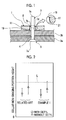
- Fig. 1 is a schematic configuration diagram schematically showing a lock bolt which is fastened by a swaging tool according to Example 1.
- Fig. 2 is an explanatory diagram when comparing the heights of a non-swaging portions of collars when using the swaging tool of Example 1 and a swaging tool of the related art.
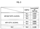
- Fig. 3 is a table comparing coefficients of friction.
- a swaging tool 1 of Example 1 is a tool for fastening a lock bolt 5 to a pair of plates 3a and 3b superimposed on each other, which is a fastened part.
- the lock bolt 5 which is fastened to the pair of plates 3a and 3b by the swaging tool 1 will be described with reference to Fig. 1 .
- the lock bolt 5 has a fastening pin 7 which extends in an axial direction, and a collar 8 which is swaged to the fastening pin 7.
- the fastening pin 7 is configured to include a pinhead 7a which is provided on one side in the axial direction, a central pin main body 7b, and a pintail 7c which is provided on the other side in the axial direction. Further, a portion between the pin main body 7b and the pintail 7c becomes a breaking portion 7d, and the breaking portion 7d can be broken by applying a predetermined tensile load to the pintail 7c relative to the pin main body 7b.
- the fastening pin 7 is inserted into a fastening hole 4 which is formed to penetrate in a lamination direction of the pair of plates 3a and 3b.
- the pinhead 7a is located on the side of the plate 3a on one side (the lower side of Fig. 1 ) and the pintail 7c is located on the side of the plate 3b on the other side (the upper side of Fig. 1 ) across the pair of plates 3a and 3b.
- a portion thereof is located in the fastening hole 4 and the other portion is located on the side of the plate 3b on the other side (the upper side of Fig. 1 ).
- the collar 8 has a cylindrical shape and is mounted from the pintail 7c side of the fastening pin 7.
- the collar 8 mounted on the fastening pin 7 is moved to the plate 3b side (the pinhead 7a side) in the axial direction by the swaging tool 1, thereby being brought into contact with the plate 3b, and is swaged to the pin main body 7b of the fastening pin 7 in a state where the collar 8 is in contact with the plate 3b. Thereafter, a predetermined tensile load is applied to the fastening pin 7, whereby the breaking portion 7d is broken, and thus the pintail 7c is broken and removed.
- the swaging tool 1 As shown in Fig. 1 , the swaging tool 1 has a swaging die 11 in which a swaging hole 19 for swaging the collar 8 is formed to penetrate it.
- the swaging die 11 is a member which comes into contact with the collar 8 and is pushed in toward the plate 3b side.
- the collar 8 mounted on the fastening pin 7 is pressed by pushing the swaging die 11 in, whereby the swaging hole 19 which is formed in the swaging die 11 swages the collar 8.
- the shape of the inner peripheral surface of the swaging hole 19 is made to be a shape curved in a penetration direction. That is, the swaging hole 19 is made such that the diameter on the inlet side on which the collar 8 is pushed in is wider than the diameter of the collar 8 and the diameter becomes narrower as it goes toward the outlet side.
- the swaging hole 19 has, at a top portion on the center side, the narrowest (smallest) diameter which is smaller than the diameter of the collar 8. Further, the swaging hole 19 is made to become wider as it goes toward the outlet side from the top portion on the center side.
- a low-friction coating film 21 is formed on the inner peripheral surface of the swaging hole 19.
- the low-friction coating film 21 is formed in at least an area from the inlet side to the top portion, and in Example 1, the low-friction coating film 21 is formed on the whole surface.
- the low-friction coating film 21 is a film formed by diamond-like carbon coating (DLC coating).
- the low-friction coating film 21 formed by the DLC coating also functions as a wear-resistant coating film, and therefore, the low-friction coating film 21 is a coating film having low frictional properties and wear resistance.
- the DLC coating is performed by physical vapor deposition.
- the DLC coating is performed by physical vapor deposition or chemical vapor deposition.
- the low-friction coating film 21 DLC-coated by the physical vapor deposition can be formed in a harder film, compared to the case of DLC coating by the chemical vapor deposition.
- the low-friction coating film 21 becomes a coating film having lower frictional properties and more wear resistance.
- the low-friction coating film 21 formed in this manner has the coefficient of friction of less than or equal to at least 0.35, and more suitably, the coefficient of friction is less than or equal to 0.12.
- a fastening state of the collar 8 when using a swaging tool of the related art and a fastening state of the collar 8 when using the swaging tool 1 of Example 1 are compared with each other with reference to Fig. 2 .
- the vertical axis thereof represents the height of a non-swaging portion of the collar 8.
- a set of white circle and white triangle shown on the left side shows the fastening state of the collar 8 when using the swaging tool of the related art
- a set of white circle and white triangle shown on the right side shows the fastening state of the collar 8 when using the swaging tool 1 of Example 1.
- the white circle is a case where a lubricant such as cetyl alcohol is applied to the outer peripheral surface of the collar 8
- the white triangle is a case where the lubricant such as cetyl alcohol applied to the outer peripheral surface of the collar 8 has come off.
- a dotted line L is a prescribed line indicating a prescribed height of a swaging portion for determining whether the fastening state of the collar 8 is good or bad, and if the height of the non-swaging portion of the collar 8 is lower than the prescribed line L, the fastening state of the collar 8 is regarded as being good, and on the other hand, if the height of the non-swaging portion is higher than the prescribed line L, the fastening state of the collar 8 is regarded as being bad.
- the coefficient of friction when using the swaging tool of the related art and the coefficient of friction when using the swaging tool 1 of Example 1 are compared with each other with reference to Fig. 3 .
- the collars 8 of No. 1 to No. 3 which are samples are the collars 8 with the lubricant such as cetyl alcohol came off therefrom, and the coefficients of friction thereof are the coefficients of friction when fastening the collars 8 by using the swaging tool of the related art.
- the collars 8 which are samples are the collars 8 in which the lubricant such as cetyl alcohol is applied thereto, and the coefficients of friction thereof are the coefficients of friction when fastening the collars 8 by using the swaging tool of the related art.
- the collar 8 of No. 6 which is a sample is the collar 8 with the lubricant such as cetyl alcohol came off therefrom, and the coefficient of friction thereof is the coefficient of friction when fastening the collar 8 by using the swaging tool 1 of Example 1.
- the coefficient of friction is "0.3558". In the case of No. 2, the coefficient of friction is "0.3550”. In the case of No. 3, the coefficient of friction is "0.3597”. From the above, the coefficient of friction when the collar 8 with the lubricant such as cetyl alcohol came off therefrom is fastened by using the swaging tool of the related art, that is, the coefficient of friction in a case where the fastening failure of the collar 8 occurs, becomes the coefficient of friction shown in each of No. 1 to No. 3.
- the coefficient of friction is "0.0866". In the case of No. 5, the coefficient of friction is "0.0576". From the above, the coefficient of friction when the collar 8 with the lubricant such as cetyl alcohol applied thereto is fastened by using the swaging tool of the related art, that is, the coefficient of friction in a case where the collar 8 can be favorably fastened, becomes the coefficient of friction shown in each of No. 4 and No. 5.
- the coefficient of friction is "0.1289". From the above, the coefficient of friction when the collar 8 with the lubricant such as cetyl alcohol came off therefrom is fastened by using the swaging tool 1 of Example 1, that is, the coefficient of friction in a case where the collar 8 can be nearly favorably fastened, becomes the coefficient of friction shown in No. 6. Accordingly, it was confirmed that it was favorable if the coefficient of friction of the low-friction coating film 21 is set to be less than or equal to at least 0.35 and the collar 8 could be nearly favorably fastened by setting the coefficient of friction to be more suitably 0.12 ⁇ 0.01. Accordingly, if the coefficient of friction of the low-friction coating film 21 is set to be less than or equal to 0.12, the collar 8 can be more favorably fastened.
- the low-friction coating film 21 can be formed on the inner peripheral surface of the swaging hole 19 which is formed in the swaging die 11, and therefore, even if the lubricant applied to the collar 8 comes off, it is possible to suppress an increase in friction between the swaging tool 1 and the collar 8. For this reason, even if the lubricant applied to the collar 8 comes off, it becomes possible to suitably swage the collar 8 to the fastening pin 7.
- the coefficient of friction of the low-friction coating film 21 can be set to be less than or equal to at least 0.35 and more suitably, less than or equal to 0.12, and therefore, it is possible to suitably suppress an increase in friction between the swaging tool 1 and the collar 8.
- the low-friction coating film 21 is formed by performing DLC coating by physical vapor deposition, and therefore, the low-friction coating film 21 can be made to be hard, and thus the low-friction coating film 21 can become a coating film having high low-frictional properties and can become a coating film having wear resistance. For this reason, it is possible to suppress wear of the swaging hole 19 which is formed in the swaging die 11, and therefore, it is possible to attain improvement in the tool life of the swaging tool 1.
- the low-friction coating film 21 can be formed on the whole surface of the inner peripheral surface of the swaging hole 19. For this reason, it is possible to form the low-friction coating film 21 on the inner peripheral surface of the swaging hole 19, with which the collar 8 comes into contact, and thus it is possible to suitably reduce friction at a portion at which the inner peripheral surface of the swaging hole 19 and the collar 8 come into contact with each other. Further, in Example 1, the low-friction coating film 21 is formed on the whole surface of the inner peripheral surface of the swaging hole 19. However, it is sufficient if the low-friction coating film 21 is formed in at least an area from the inlet side to the top portion of the swaging hole 19.
- the low-friction coating film 21 is formed by the DLC coating.
- low-friction coating for example, diamond coating, titanium light coating, titanium aluminum coating, or the like may be applied, and it is acceptable if it is coating capable of reducing the coefficient of friction.
- the swaging tool according to Example 2 has a configuration in which the inner peripheral surface of the swaging hole 19 is made to be a smooth surface and the low-friction coating film 21 of the swaging tool 1 shown in Fig. 1 of Example 1 is omitted.
- the drawing of the swaging tool of Example 2 corresponds to a drawing in which the low-friction coating film 21 of Fig. 1 is omitted, and therefore, the illustration of the swaging tool of Example 2 is omitted.
- the coefficient of friction of the inner peripheral surface of the swaging hole 19 is set to be the coefficient of friction of less than or equal to at least 0.35. That is, in the swaging tool of Example 2, the inner peripheral surface of the swaging hole 19 is processed so as to become a smooth surface having the coefficient of friction of less than or equal to at least 0.35. Further, more preferably, the inner peripheral surface of the swaging hole 19 is made to be a smooth surface having the coefficient of friction of less than or equal to 0.12.
- the inner peripheral surface of the swaging hole 19 which is formed in the swaging die 11 can be formed in a smooth surface having low friction, and therefore, even if the lubricant applied to the collar 8 comes off, it is possible to suppress an increase in friction between the swaging tool and the collar 8. For this reason, even if the lubricant applied to the collar 8 comes off, it becomes possible to suitably swage the collar 8 to the fastening pin 7.
Landscapes
- Engineering & Computer Science (AREA)
- Mechanical Engineering (AREA)
- General Engineering & Computer Science (AREA)
- Insertion Pins And Rivets (AREA)
- Mounting, Exchange, And Manufacturing Of Dies (AREA)
- Connection Of Plates (AREA)
- Forging (AREA)
Abstract
Description
- The present invention relates to a swaging tool which fastens a fastened part by swaging a collar to a fastening pin.
- In the related art, a hydraulic swaging tool which swages a collar to a fastening pin by actuating a piston in a cylinder by using a fluid is known (refer to, for example, PTL 1). Further, as a swaging tool, in addition to a hydraulic swaging tool, there is a swaging tool which actuates a piston in a cylinder by pneumatic pressure.
- [PTL 1]
US Patent No. 5,548,889 - Incidentally, in a collar which is swaged by a swaging tool, a lubricant such as cetyl alcohol is applied to the surface (the outer surface) with which the swaging tool comes into contact. However, the lubricant comes off with time while it is handled. Here, in a case where the collar from which the lubricant came off is swaged by using the swaging tool of
PTL 1, friction between the swaging tool and the collar increases. In this case, fastening failure in which a pintail breaks in a state where only a portion of the collar is swaged to a fastening pin easily occurs. If the fastening failure occurs, it is necessary to remove (the fastening pin and) the collar subjected to the fastening failure and perform fastening work again, and thus, workability is lowered. - Therefore, the present invention has an object to provide a swaging tool in which it is possible to suitably swage a collar to a fastening pin.
- According to an aspect of the present invention, there is provided a swaging tool in which a pinhead of a fastening pin is located on one side of a fastened part into which the fastening pin is inserted, a pintail of the fastening pin is located on the other side of the fastened part, a collar mounted on the pintail side of the fastening pin is moved to the pinhead side so as to come into contact with the fastened part, the collar is swaged to the fastening pin in a state where the collar is in contact with the fastened part, and a tensile load is applied to the pintail, thereby breaking and removing the pintail, whereby the fastened part is fastened, the swaging tool including: a swaging die in which there is formed a swaging hole which is brought into contact with the collar, thereby swaging the collar, wherein a low-friction coating film is formed on an inner peripheral surface of the swaging hole.
- According to this configuration, the low-friction coating film can be formed on the inner peripheral surface of the swaging hole which is formed in the swaging die, and therefore, even if a lubricant applied to the collar comes off, it is possible to suppress an increase in friction between the swaging tool and the collar. For this reason, even if the lubricant applied to the collar comes off, it becomes possible to suitably swage the collar to the fastening pin. Further, as low-friction coating, there is diamond-like carbon coating (DLC coating), diamond coating, titanium light coating, titanium aluminum coating, or the like.
- Further, it is preferable that a coefficient of friction of the low-friction coating film is less than or equal to 0.35 and it is more preferable that the coefficient of friction of the low-friction coating film is less than or equal to 0.12.
- According to this configuration, it is possible to suitably suppress an increase in friction between the swaging tool and the collar. Further, it is preferable that the coefficient of friction of the low-friction coating film is as low as possible.
- Further, it is preferable that the low-friction coating film also has a function as a wear-resistant coating film.
- According to this configuration, it is possible to suppress wear of the swaging hole which is formed in the swaging die. For this reason, it is possible to attain improvement in the tool life of the swaging tool.
- Further, it is preferable that the low-friction coating film is a film formed by diamond-like carbon coating.
- According to this configuration, it is possible to make the low-friction coating film a coating film having low frictional properties and wear resistance.
- Further, it is preferable that the diamond-like carbon coating is performed by physical vapor deposition.
- According to this configuration, the DLC coating which is formed by physical vapor deposition (PVD) forms a coating into which it is difficult for hydrogen to enter at the time of film formation, and therefore, compared to a case of performing the DLC coating by, for example, chemical vapor deposition (CVD), it is possible to make the low-friction coating film a hard film. For this reason, even in the DLC coating, it is possible to make the low-friction coating film a coating film having lower frictional properties and more wear resistance.
- Further, it is preferable that the swaging hole is formed such that a diameter thereof is wide on the inlet side on which the collar is pushed in, and is the narrowest at a top portion on the center side, and is wider than the diameter in the top portion on the outlet side, and the low-friction coating film is formed in at least an area from the inlet side to the top portion of the swaging hole.
- According to this configuration, it is possible to form the low-friction coating film in an appropriate area with respect to the inner peripheral surface of the swaging hole.
- According to another aspect of the present invention, there is provided a swaging tool in which a pinhead of a fastening pin is located on one side of a fastened part into which the fastening pin is inserted, a pintail of the fastening pin is located on the other side of the fastened part, a collar mounted on the pintail side of the fastening pin is moved to the pinhead side so as to come into contact with the fastened part, the collar is swaged to the fastening pin in a state where the collar is in contact with the fastened part, and a tensile load is applied to the pintail, thereby breaking and removing the pintail, whereby the fastened part is fastened, the swaging tool including: a swaging die in which there is formed a swaging hole which is brought into contact with the collar, thereby swaging the collar, wherein a coefficient of friction in an inner peripheral surface of the swaging hole is less than or equal to 0.35.
- According to this configuration, the inner peripheral surface of the swaging hole which is formed in the swaging die can be formed in a smooth surface having low friction, and therefore, even if the lubricant applied to the collar comes off, it is possible to suppress an increase in friction between the swaging tool and the collar. For this reason, even if the lubricant applied to the collar comes off, it becomes possible to suitably swage the collar to the fastening pin. Further, more preferably, it is preferable that the coefficient of friction in the inner peripheral surface of the swaging hole is less than or equal to 0.12.
- Further, it is preferable that a lubricant is applied to the collar before the collar is swaged.
- According to this configuration, it is possible to more suitably suppress an increase in friction between the swaging tool and the collar.
-
-
Fig. 1 is a schematic configuration diagram schematically showing a lock bolt which is fastened by a swaging tool according to Example 1. -
Fig. 2 is an explanatory diagram when comparing the heights of non-swaging portions of collars when using the swaging tool of Example 1 and a swaging tool of the related art. -
Fig. 3 is a table comparing coefficients of friction. - Hereinafter, examples according to the present invention will be described in detail based on the drawings. In addition, the present invention is not limited by these examples. Further, in constituent elements in the following examples, elements with which those skilled in the art can easily replace them, or substantially the same elements are included.
-
Fig. 1 is a schematic configuration diagram schematically showing a lock bolt which is fastened by a swaging tool according to Example 1.Fig. 2 is an explanatory diagram when comparing the heights of a non-swaging portions of collars when using the swaging tool of Example 1 and a swaging tool of the related art.Fig. 3 is a table comparing coefficients of friction. - A
swaging tool 1 of Example 1 is a tool for fastening alock bolt 5 to a pair ofplates lock bolt 5 which is fastened to the pair ofplates swaging tool 1 will be described with reference toFig. 1 . - As shown in
Fig. 1 , thelock bolt 5 has a fasteningpin 7 which extends in an axial direction, and a collar 8 which is swaged to the fasteningpin 7. The fasteningpin 7 is configured to include apinhead 7a which is provided on one side in the axial direction, a central pinmain body 7b, and a pintail 7c which is provided on the other side in the axial direction. Further, a portion between the pinmain body 7b and the pintail 7c becomes a breakingportion 7d, and the breakingportion 7d can be broken by applying a predetermined tensile load to the pintail 7c relative to the pinmain body 7b. - The fastening
pin 7 is inserted into a fastening hole 4 which is formed to penetrate in a lamination direction of the pair ofplates pin 7 which is inserted into the fastening hole 4, at the time of fastening, thepinhead 7a is located on the side of theplate 3a on one side (the lower side ofFig. 1 ) and thepintail 7c is located on the side of theplate 3b on the other side (the upper side ofFig. 1 ) across the pair ofplates main body 7b, a portion thereof is located in the fastening hole 4 and the other portion is located on the side of theplate 3b on the other side (the upper side ofFig. 1 ). - The collar 8 has a cylindrical shape and is mounted from the pintail 7c side of the fastening
pin 7. The collar 8 mounted on the fasteningpin 7 is moved to theplate 3b side (thepinhead 7a side) in the axial direction by theswaging tool 1, thereby being brought into contact with theplate 3b, and is swaged to the pinmain body 7b of the fasteningpin 7 in a state where the collar 8 is in contact with theplate 3b. Thereafter, a predetermined tensile load is applied to the fasteningpin 7, whereby the breakingportion 7d is broken, and thus thepintail 7c is broken and removed. - Next, the
swaging tool 1 will be described with reference toFig. 1 . As shown inFig. 1 , theswaging tool 1 has a swaging die 11 in which aswaging hole 19 for swaging the collar 8 is formed to penetrate it. - The swaging die 11 is a member which comes into contact with the collar 8 and is pushed in toward the
plate 3b side. The collar 8 mounted on thefastening pin 7 is pressed by pushing the swaging die 11 in, whereby theswaging hole 19 which is formed in the swaging die 11 swages the collar 8. The shape of the inner peripheral surface of theswaging hole 19 is made to be a shape curved in a penetration direction. That is, theswaging hole 19 is made such that the diameter on the inlet side on which the collar 8 is pushed in is wider than the diameter of the collar 8 and the diameter becomes narrower as it goes toward the outlet side. Further, theswaging hole 19 has, at a top portion on the center side, the narrowest (smallest) diameter which is smaller than the diameter of the collar 8. Further, theswaging hole 19 is made to become wider as it goes toward the outlet side from the top portion on the center side. - A low-
friction coating film 21 is formed on the inner peripheral surface of theswaging hole 19. The low-friction coating film 21 is formed in at least an area from the inlet side to the top portion, and in Example 1, the low-friction coating film 21 is formed on the whole surface. The low-friction coating film 21 is a film formed by diamond-like carbon coating (DLC coating). The low-friction coating film 21 formed by the DLC coating also functions as a wear-resistant coating film, and therefore, the low-friction coating film 21 is a coating film having low frictional properties and wear resistance. - Further, the DLC coating is performed by physical vapor deposition. Here, the DLC coating is performed by physical vapor deposition or chemical vapor deposition. However, in the DLC coating which is performed by the physical vapor deposition, at the time of formation of the low-
friction coating film 21, it is difficult for hydrogen to be mixed in, compared to the chemical vapor deposition. For this reason, the low-friction coating film 21 DLC-coated by the physical vapor deposition can be formed in a harder film, compared to the case of DLC coating by the chemical vapor deposition. For this reason, among the DLC coatings, the low-friction coating film 21 becomes a coating film having lower frictional properties and more wear resistance. The low-friction coating film 21 formed in this manner has the coefficient of friction of less than or equal to at least 0.35, and more suitably, the coefficient of friction is less than or equal to 0.12. - Next, a fastening state of the collar 8 when using a swaging tool of the related art and a fastening state of the collar 8 when using the
swaging tool 1 of Example 1 are compared with each other with reference toFig. 2 . InFig. 2 , the vertical axis thereof represents the height of a non-swaging portion of the collar 8. Further, inFig. 2 , a set of white circle and white triangle shown on the left side shows the fastening state of the collar 8 when using the swaging tool of the related art, and a set of white circle and white triangle shown on the right side shows the fastening state of the collar 8 when using theswaging tool 1 of Example 1. Here, the white circle is a case where a lubricant such as cetyl alcohol is applied to the outer peripheral surface of the collar 8, and the white triangle is a case where the lubricant such as cetyl alcohol applied to the outer peripheral surface of the collar 8 has come off. Further, a dotted line L is a prescribed line indicating a prescribed height of a swaging portion for determining whether the fastening state of the collar 8 is good or bad, and if the height of the non-swaging portion of the collar 8 is lower than the prescribed line L, the fastening state of the collar 8 is regarded as being good, and on the other hand, if the height of the non-swaging portion is higher than the prescribed line L, the fastening state of the collar 8 is regarded as being bad. - As shown in
Fig. 2 , in the swaging tool of the related art, in a case where the lubricant is applied to the collar 8, it was confirmed that the collar 8 could be favorably fastened. On the other hand, in the swaging tool of the related art, in a case where the lubricant is not applied to the collar 8, it was confirmed that there was a case where fastening failure of the collar 8 occurs. - In contrast, in the
swaging tool 1 of Example 1, in a case where the lubricant is applied to the collar 8, it was confirmed that the collar 8 could be favorably fastened. Further, in theswaging tool 1 of Example 1, in a case where the lubricant is not applied to the collar 8, it was confirmed that the collar 8 could be nearly favorably fastened. That is, in theswaging tool 1 of Example 1, although there is a case where fastening failure of the collar 8 occurs, it was confirm that the fastening failure could be sufficiently suppressed, compared to the swaging tool of the related art. - Next, the coefficient of friction when using the swaging tool of the related art and the coefficient of friction when using the
swaging tool 1 of Example 1 are compared with each other with reference toFig. 3 . InFig. 3 , the collars 8 of No. 1 to No. 3 which are samples are the collars 8 with the lubricant such as cetyl alcohol came off therefrom, and the coefficients of friction thereof are the coefficients of friction when fastening the collars 8 by using the swaging tool of the related art. InFig. 3 , the collars 8 of No. 4 and No. 5 which are samples are the collars 8 in which the lubricant such as cetyl alcohol is applied thereto, and the coefficients of friction thereof are the coefficients of friction when fastening the collars 8 by using the swaging tool of the related art. InFig. 3 , the collar 8 of No. 6 which is a sample is the collar 8 with the lubricant such as cetyl alcohol came off therefrom, and the coefficient of friction thereof is the coefficient of friction when fastening the collar 8 by using theswaging tool 1 of Example 1. - As shown in
Fig. 3 , in the case of No. 1, the coefficient of friction is "0.3558". In the case of No. 2, the coefficient of friction is "0.3550". In the case of No. 3, the coefficient of friction is "0.3597". From the above, the coefficient of friction when the collar 8 with the lubricant such as cetyl alcohol came off therefrom is fastened by using the swaging tool of the related art, that is, the coefficient of friction in a case where the fastening failure of the collar 8 occurs, becomes the coefficient of friction shown in each of No. 1 to No. 3. - Further, as shown in
Fig. 3 , in the case of No. 4, the coefficient of friction is "0.0866". In the case of No. 5, the coefficient of friction is "0.0576". From the above, the coefficient of friction when the collar 8 with the lubricant such as cetyl alcohol applied thereto is fastened by using the swaging tool of the related art, that is, the coefficient of friction in a case where the collar 8 can be favorably fastened, becomes the coefficient of friction shown in each of No. 4 and No. 5. - Further, as shown in
Fig. 3 , in the case of No. 6, the coefficient of friction is "0.1289". From the above, the coefficient of friction when the collar 8 with the lubricant such as cetyl alcohol came off therefrom is fastened by using theswaging tool 1 of Example 1, that is, the coefficient of friction in a case where the collar 8 can be nearly favorably fastened, becomes the coefficient of friction shown in No. 6. Accordingly, it was confirmed that it was favorable if the coefficient of friction of the low-friction coating film 21 is set to be less than or equal to at least 0.35 and the collar 8 could be nearly favorably fastened by setting the coefficient of friction to be more suitably 0.12±0.01. Accordingly, if the coefficient of friction of the low-friction coating film 21 is set to be less than or equal to 0.12, the collar 8 can be more favorably fastened. - As described above, according to the configuration of Example 1, the low-
friction coating film 21 can be formed on the inner peripheral surface of theswaging hole 19 which is formed in the swaging die 11, and therefore, even if the lubricant applied to the collar 8 comes off, it is possible to suppress an increase in friction between theswaging tool 1 and the collar 8. For this reason, even if the lubricant applied to the collar 8 comes off, it becomes possible to suitably swage the collar 8 to thefastening pin 7. - Further, according to the configuration of Example 1, the coefficient of friction of the low-
friction coating film 21 can be set to be less than or equal to at least 0.35 and more suitably, less than or equal to 0.12, and therefore, it is possible to suitably suppress an increase in friction between theswaging tool 1 and the collar 8. - Further, according to the configuration of Example 1, the low-
friction coating film 21 is formed by performing DLC coating by physical vapor deposition, and therefore, the low-friction coating film 21 can be made to be hard, and thus the low-friction coating film 21 can become a coating film having high low-frictional properties and can become a coating film having wear resistance. For this reason, it is possible to suppress wear of theswaging hole 19 which is formed in the swaging die 11, and therefore, it is possible to attain improvement in the tool life of theswaging tool 1. - Further, according to the configuration of Example 1, the low-
friction coating film 21 can be formed on the whole surface of the inner peripheral surface of theswaging hole 19. For this reason, it is possible to form the low-friction coating film 21 on the inner peripheral surface of theswaging hole 19, with which the collar 8 comes into contact, and thus it is possible to suitably reduce friction at a portion at which the inner peripheral surface of theswaging hole 19 and the collar 8 come into contact with each other. Further, in Example 1, the low-friction coating film 21 is formed on the whole surface of the inner peripheral surface of theswaging hole 19. However, it is sufficient if the low-friction coating film 21 is formed in at least an area from the inlet side to the top portion of theswaging hole 19. - Further, in Example 1, the low-
friction coating film 21 is formed by the DLC coating. However, there is no limitation to this configuration. As low-friction coating, for example, diamond coating, titanium light coating, titanium aluminum coating, or the like may be applied, and it is acceptable if it is coating capable of reducing the coefficient of friction. - Further, in a case where the collar 8 with the lubricant came off therefrom is swaged by using the
swaging tool 1 of Example 1, a configuration is also acceptable in which the lubricant is applied to the collar 8 again in advance and thereafter, the collar 8 is swaged. In this case, it is possible to more suitably, suppress an increase in friction between theswaging tool 1 and the collar 8. - Next, a swaging tool according to Example 2 will be described. The swaging tool according to Example 2 has a configuration in which the inner peripheral surface of the
swaging hole 19 is made to be a smooth surface and the low-friction coating film 21 of theswaging tool 1 shown inFig. 1 of Example 1 is omitted. For this reason, the drawing of the swaging tool of Example 2 corresponds to a drawing in which the low-friction coating film 21 ofFig. 1 is omitted, and therefore, the illustration of the swaging tool of Example 2 is omitted. - In the swaging tool according to Example 2, the coefficient of friction of the inner peripheral surface of the
swaging hole 19 is set to be the coefficient of friction of less than or equal to at least 0.35. That is, in the swaging tool of Example 2, the inner peripheral surface of theswaging hole 19 is processed so as to become a smooth surface having the coefficient of friction of less than or equal to at least 0.35. Further, more preferably, the inner peripheral surface of theswaging hole 19 is made to be a smooth surface having the coefficient of friction of less than or equal to 0.12. - As described above, also in the configuration of Example 2, the inner peripheral surface of the
swaging hole 19 which is formed in the swaging die 11 can be formed in a smooth surface having low friction, and therefore, even if the lubricant applied to the collar 8 comes off, it is possible to suppress an increase in friction between the swaging tool and the collar 8. For this reason, even if the lubricant applied to the collar 8 comes off, it becomes possible to suitably swage the collar 8 to thefastening pin 7. -
- 1: swaging tool
- 5: lock bolt
- 7: fastening pin
- 8: collar
- 11: swaging die
- 19: swaging hole
- 21: low-friction coating film
Claims (10)
- A swaging tool in which a pinhead of a fastening pin is located on one side of a fastened part into which the fastening pin is inserted, a pintail of the fastening pin is located on the other side of the fastened part, a collar mounted on the pintail side of the fastening pin is moved to the pinhead side so as to come into contact with the fastened part, the collar is swaged to the fastening pin in a state where the collar is in contact with the fastened part, and a tensile load is applied to the pintail, thereby breaking and removing the pintail, whereby the fastened part is fastened, the swaging tool comprising:a swaging die in which there is formed a swaging hole which is brought into contact with the collar, thereby swaging the collar,wherein a low-friction coating film is formed on an inner peripheral surface of the swaging hole.
- The swaging tool according to Claim 1, wherein a coefficient of friction of the low-friction coating film is less than or equal to 0.35.
- The swaging tool according to Claim 2, wherein the coefficient of friction of the low-friction coating film is less than or equal to 0.12.
- The swaging tool according to any one of Claims 1 to 3, wherein the low-friction coating film also has a function as a wear-resistant coating film.
- The swaging tool according to any one of Claims 1 to 4, wherein the low-friction coating film is a film formed by diamond-like carbon coating.
- The swaging tool according to Claim 5, wherein the diamond-like carbon coating is performed by physical vapor deposition.
- The swaging tool according to any one of Claims 1 to 6, wherein the swaging hole is formed such that a diameter thereof is wide on the inlet side on which the collar is pushed in, and is the narrowest at a top portion on the center side, and is wider than the diameter in the top portion on the outlet side, and
the low-friction coating film is formed in at least an area from the inlet side to the top portion of the swaging hole. - A swaging tool in which a pinhead of a fastening pin is located on one side of a fastened part into which the fastening pin is inserted, a pintail of the fastening pin is located on the other side of the fastened part, a collar mounted on the pintail side of the fastening pin is moved to the pinhead side so as to come into contact with the fastened part, the collar is swaged to the fastening pin in a state where the collar is in contact with the fastened part, and a tensile load is applied to the pintail, thereby breaking and removing the pintail, whereby the fastened part is fastened, the swaging tool comprising:a swaging die in which there is formed a swaging hole which is brought into contact with the collar, thereby swaging the collar,wherein a coefficient of friction in an inner peripheral surface of the swaging hole is less than or equal to 0.35.
- The swaging tool according to Claim 8, wherein the coefficient of friction in the inner peripheral surface of the swaging hole is less than or equal to 0.12.
- The swaging tool according to any one of Claims 1 to 9, wherein a lubricant is applied to the collar before the collar is swaged.
Applications Claiming Priority (2)
| Application Number | Priority Date | Filing Date | Title |
|---|---|---|---|
| JP2013253679A JP6192521B2 (en) | 2013-12-06 | 2013-12-06 | Swage tool |
| PCT/JP2014/082049 WO2015083756A1 (en) | 2013-12-06 | 2014-12-03 | Swaging tool |
Publications (3)
| Publication Number | Publication Date |
|---|---|
| EP3045237A1 true EP3045237A1 (en) | 2016-07-20 |
| EP3045237A4 EP3045237A4 (en) | 2016-09-28 |
| EP3045237B1 EP3045237B1 (en) | 2018-07-04 |
Family
ID=53273517
Family Applications (1)
| Application Number | Title | Priority Date | Filing Date |
|---|---|---|---|
| EP14867285.0A Active EP3045237B1 (en) | 2013-12-06 | 2014-12-03 | Swaging tool |
Country Status (4)
| Country | Link |
|---|---|
| US (1) | US9610631B2 (en) |
| EP (1) | EP3045237B1 (en) |
| JP (1) | JP6192521B2 (en) |
| WO (1) | WO2015083756A1 (en) |
Cited By (1)
| Publication number | Priority date | Publication date | Assignee | Title |
|---|---|---|---|---|
| EP3326730A1 (en) * | 2016-11-29 | 2018-05-30 | The Boeing Company | Tooling with permanent low friction coating for setting interference-fit fasteners |
Families Citing this family (2)
| Publication number | Priority date | Publication date | Assignee | Title |
|---|---|---|---|---|
| CN107096832A (en) * | 2017-07-07 | 2017-08-29 | 东莞市景雄五金电子有限公司 | A processing method for riveting wire contacts in a high-speed stamping die |
| US11052454B2 (en) | 2019-07-23 | 2021-07-06 | The Boeing Company | Dynamic collar swage conformance checking based on swage tool parameters |
Family Cites Families (15)
| Publication number | Priority date | Publication date | Assignee | Title |
|---|---|---|---|---|
| US3792933A (en) * | 1971-12-20 | 1974-02-19 | Vsi Corp | High-strength fastening system |
| US3983304A (en) * | 1973-09-19 | 1976-09-28 | Hi-Shear Corporation | Fastener with protective metal-organic base coating |
| US4557033A (en) * | 1983-07-11 | 1985-12-10 | Fatigue Technology, Inc. | Method of cold expanding and sizing fastener holes |
| US5315755A (en) | 1989-05-31 | 1994-05-31 | Huck Patents, Inc. | Fastener system including a swage fastener and a tool for installing same |
| US6233802B1 (en) * | 1999-08-06 | 2001-05-22 | Huck International, Inc. | Low swage load fastener and fastening system |
| JP2003522026A (en) * | 2000-02-09 | 2003-07-22 | ストレスウェイヴ・インコーポレーテッド | METHOD AND APPARATUS FOR PRODUCING A STRUCTURE WITH IMPROVED LIFE LIFE |
| JP3612295B2 (en) * | 2001-08-23 | 2005-01-19 | 未来工業株式会社 | Diameter expansion tool for fluid pipe |
| US7025550B2 (en) * | 2002-08-08 | 2006-04-11 | Huck International, Inc. | Pull type swage fasteners with removable mandrel |
| JP4039228B2 (en) | 2002-12-13 | 2008-01-30 | 株式会社ジェイテクト | Power transmission chain and power transmission device |
| JP3900430B2 (en) * | 2003-04-01 | 2007-04-04 | 日産自動車株式会社 | Mandrel for assembly-type camshaft and method for expanding tube of assembly-type camshaft using the same |
| US7677852B2 (en) * | 2004-08-30 | 2010-03-16 | Acument Intellectual Properties, Llc | Multi-lobular lockbolt |
| US7677853B2 (en) * | 2004-08-30 | 2010-03-16 | Acument Intellectual Properties, Llc | Multi-lobular lockbolt and system |
| US7465234B2 (en) * | 2004-09-13 | 2008-12-16 | The Boeing Company | Hybrid fastening system and associated method of fastening |
| US7891924B2 (en) * | 2006-11-03 | 2011-02-22 | Huck International, Inc. | Low swage load fastening system and method |
| JP2013176803A (en) * | 2012-02-10 | 2013-09-09 | Kobe Steel Ltd | Press-molded article, and method for manufacturing the same |
-
2013
- 2013-12-06 JP JP2013253679A patent/JP6192521B2/en active Active
-
2014
- 2014-12-03 US US15/029,247 patent/US9610631B2/en active Active
- 2014-12-03 EP EP14867285.0A patent/EP3045237B1/en active Active
- 2014-12-03 WO PCT/JP2014/082049 patent/WO2015083756A1/en not_active Ceased
Cited By (2)
| Publication number | Priority date | Publication date | Assignee | Title |
|---|---|---|---|---|
| EP3326730A1 (en) * | 2016-11-29 | 2018-05-30 | The Boeing Company | Tooling with permanent low friction coating for setting interference-fit fasteners |
| CN108115076A (en) * | 2016-11-29 | 2018-06-05 | 波音公司 | For the enhancing instrument of Interference-fit fasteners |
Also Published As
| Publication number | Publication date |
|---|---|
| US20160256916A1 (en) | 2016-09-08 |
| US9610631B2 (en) | 2017-04-04 |
| EP3045237A4 (en) | 2016-09-28 |
| JP6192521B2 (en) | 2017-09-06 |
| JP2015112606A (en) | 2015-06-22 |
| WO2015083756A1 (en) | 2015-06-11 |
| EP3045237B1 (en) | 2018-07-04 |
Similar Documents
| Publication | Publication Date | Title |
|---|---|---|
| US9091290B2 (en) | Punch rivet and die | |
| US10876565B2 (en) | Self-piercing rivet | |
| EP3284959B1 (en) | Blind fastener | |
| EP3045237B1 (en) | Swaging tool | |
| US11156246B2 (en) | Blind rivet having a shoulder shank and associated installation method | |
| US11028868B2 (en) | Press-fit connection between a high-strength component and a press-fit element, method for making such a press-fit connection, and press-fit element for such a press-fit connection | |
| EP3322905B1 (en) | Quick connect mechanism for a draw stud assembly | |
| US20150252833A1 (en) | Lockbolt | |
| EP2787221A1 (en) | Pierce nut for high-strength steel sheet | |
| US20130202382A1 (en) | Swage indicating collar | |
| EP2549142A1 (en) | Bleeder plug | |
| US9897131B2 (en) | Method and a connecting system for the joining of moulded parts | |
| US10508688B2 (en) | Bearing device and method of manufacturing the same | |
| US20080219798A1 (en) | Stem plug modifications improving wiredraw functionality | |
| US20170056959A1 (en) | Installation tooling system for buckle and swage type fastener | |
| US20160151825A1 (en) | Die, joining tool and die production method | |
| JP5747448B2 (en) | Punching hole punching and punching hole machining method with improved fatigue characteristics and hydrogen cracking resistance | |
| CN108626223B (en) | Connection system and method | |
| EP3385532B1 (en) | High-pressure fuel injection pipe with connecting head portion, and method of molding connecting head portion | |
| US20100180658A1 (en) | Crankshaft production method and production apparatus | |
| EP3829796B1 (en) | Rivet insertion method and apparatus | |
| US10670075B2 (en) | Thrust roller bearing | |
| US9200708B2 (en) | Piston retention apparatus and method | |
| CN204003996U (en) | Tapered roller bearing | |
| US11745250B2 (en) | Swaging device and swaging method |
Legal Events
| Date | Code | Title | Description |
|---|---|---|---|
| PUAI | Public reference made under article 153(3) epc to a published international application that has entered the european phase |
Free format text: ORIGINAL CODE: 0009012 |
|
| 17P | Request for examination filed |
Effective date: 20160411 |
|
| AK | Designated contracting states |
Kind code of ref document: A1 Designated state(s): AL AT BE BG CH CY CZ DE DK EE ES FI FR GB GR HR HU IE IS IT LI LT LU LV MC MK MT NL NO PL PT RO RS SE SI SK SM TR |
|
| AX | Request for extension of the european patent |
Extension state: BA ME |
|
| A4 | Supplementary search report drawn up and despatched |
Effective date: 20160825 |
|
| RIC1 | Information provided on ipc code assigned before grant |
Ipc: B21D 37/01 20060101ALI20160819BHEP Ipc: F16B 19/08 20060101ALI20160819BHEP Ipc: B21D 37/18 20060101ALI20160819BHEP Ipc: B21D 39/00 20060101AFI20160819BHEP Ipc: F16B 5/04 20060101ALI20160819BHEP Ipc: B21J 15/02 20060101ALI20160819BHEP Ipc: B21J 15/36 20060101ALI20160819BHEP |
|
| DAX | Request for extension of the european patent (deleted) | ||
| GRAP | Despatch of communication of intention to grant a patent |
Free format text: ORIGINAL CODE: EPIDOSNIGR1 |
|
| INTG | Intention to grant announced |
Effective date: 20180215 |
|
| GRAS | Grant fee paid |
Free format text: ORIGINAL CODE: EPIDOSNIGR3 |
|
| GRAA | (expected) grant |
Free format text: ORIGINAL CODE: 0009210 |
|
| AK | Designated contracting states |
Kind code of ref document: B1 Designated state(s): AL AT BE BG CH CY CZ DE DK EE ES FI FR GB GR HR HU IE IS IT LI LT LU LV MC MK MT NL NO PL PT RO RS SE SI SK SM TR |
|
| REG | Reference to a national code |
Ref country code: GB Ref legal event code: FG4D |
|
| REG | Reference to a national code |
Ref country code: CH Ref legal event code: EP |
|
| REG | Reference to a national code |
Ref country code: AT Ref legal event code: REF Ref document number: 1013951 Country of ref document: AT Kind code of ref document: T Effective date: 20180715 |
|
| REG | Reference to a national code |
Ref country code: IE Ref legal event code: FG4D |
|
| REG | Reference to a national code |
Ref country code: DE Ref legal event code: R096 Ref document number: 602014028100 Country of ref document: DE |
|
| REG | Reference to a national code |
Ref country code: NL Ref legal event code: MP Effective date: 20180704 |
|
| REG | Reference to a national code |
Ref country code: LT Ref legal event code: MG4D |
|
| REG | Reference to a national code |
Ref country code: AT Ref legal event code: MK05 Ref document number: 1013951 Country of ref document: AT Kind code of ref document: T Effective date: 20180704 |
|
| PG25 | Lapsed in a contracting state [announced via postgrant information from national office to epo] |
Ref country code: NL Free format text: LAPSE BECAUSE OF FAILURE TO SUBMIT A TRANSLATION OF THE DESCRIPTION OR TO PAY THE FEE WITHIN THE PRESCRIBED TIME-LIMIT Effective date: 20180704 |
|
| PG25 | Lapsed in a contracting state [announced via postgrant information from national office to epo] |
Ref country code: BG Free format text: LAPSE BECAUSE OF FAILURE TO SUBMIT A TRANSLATION OF THE DESCRIPTION OR TO PAY THE FEE WITHIN THE PRESCRIBED TIME-LIMIT Effective date: 20181004 Ref country code: AT Free format text: LAPSE BECAUSE OF FAILURE TO SUBMIT A TRANSLATION OF THE DESCRIPTION OR TO PAY THE FEE WITHIN THE PRESCRIBED TIME-LIMIT Effective date: 20180704 Ref country code: SE Free format text: LAPSE BECAUSE OF FAILURE TO SUBMIT A TRANSLATION OF THE DESCRIPTION OR TO PAY THE FEE WITHIN THE PRESCRIBED TIME-LIMIT Effective date: 20180704 Ref country code: RS Free format text: LAPSE BECAUSE OF FAILURE TO SUBMIT A TRANSLATION OF THE DESCRIPTION OR TO PAY THE FEE WITHIN THE PRESCRIBED TIME-LIMIT Effective date: 20180704 Ref country code: IS Free format text: LAPSE BECAUSE OF FAILURE TO SUBMIT A TRANSLATION OF THE DESCRIPTION OR TO PAY THE FEE WITHIN THE PRESCRIBED TIME-LIMIT Effective date: 20181104 Ref country code: FI Free format text: LAPSE BECAUSE OF FAILURE TO SUBMIT A TRANSLATION OF THE DESCRIPTION OR TO PAY THE FEE WITHIN THE PRESCRIBED TIME-LIMIT Effective date: 20180704 Ref country code: GR Free format text: LAPSE BECAUSE OF FAILURE TO SUBMIT A TRANSLATION OF THE DESCRIPTION OR TO PAY THE FEE WITHIN THE PRESCRIBED TIME-LIMIT Effective date: 20181005 Ref country code: NO Free format text: LAPSE BECAUSE OF FAILURE TO SUBMIT A TRANSLATION OF THE DESCRIPTION OR TO PAY THE FEE WITHIN THE PRESCRIBED TIME-LIMIT Effective date: 20181004 Ref country code: CZ Free format text: LAPSE BECAUSE OF FAILURE TO SUBMIT A TRANSLATION OF THE DESCRIPTION OR TO PAY THE FEE WITHIN THE PRESCRIBED TIME-LIMIT Effective date: 20180704 Ref country code: LT Free format text: LAPSE BECAUSE OF FAILURE TO SUBMIT A TRANSLATION OF THE DESCRIPTION OR TO PAY THE FEE WITHIN THE PRESCRIBED TIME-LIMIT Effective date: 20180704 Ref country code: PL Free format text: LAPSE BECAUSE OF FAILURE TO SUBMIT A TRANSLATION OF THE DESCRIPTION OR TO PAY THE FEE WITHIN THE PRESCRIBED TIME-LIMIT Effective date: 20180704 |
|
| PG25 | Lapsed in a contracting state [announced via postgrant information from national office to epo] |
Ref country code: LV Free format text: LAPSE BECAUSE OF FAILURE TO SUBMIT A TRANSLATION OF THE DESCRIPTION OR TO PAY THE FEE WITHIN THE PRESCRIBED TIME-LIMIT Effective date: 20180704 Ref country code: HR Free format text: LAPSE BECAUSE OF FAILURE TO SUBMIT A TRANSLATION OF THE DESCRIPTION OR TO PAY THE FEE WITHIN THE PRESCRIBED TIME-LIMIT Effective date: 20180704 Ref country code: AL Free format text: LAPSE BECAUSE OF FAILURE TO SUBMIT A TRANSLATION OF THE DESCRIPTION OR TO PAY THE FEE WITHIN THE PRESCRIBED TIME-LIMIT Effective date: 20180704 Ref country code: ES Free format text: LAPSE BECAUSE OF FAILURE TO SUBMIT A TRANSLATION OF THE DESCRIPTION OR TO PAY THE FEE WITHIN THE PRESCRIBED TIME-LIMIT Effective date: 20180704 |
|
| REG | Reference to a national code |
Ref country code: DE Ref legal event code: R097 Ref document number: 602014028100 Country of ref document: DE |
|
| PG25 | Lapsed in a contracting state [announced via postgrant information from national office to epo] |
Ref country code: RO Free format text: LAPSE BECAUSE OF FAILURE TO SUBMIT A TRANSLATION OF THE DESCRIPTION OR TO PAY THE FEE WITHIN THE PRESCRIBED TIME-LIMIT Effective date: 20180704 Ref country code: IT Free format text: LAPSE BECAUSE OF FAILURE TO SUBMIT A TRANSLATION OF THE DESCRIPTION OR TO PAY THE FEE WITHIN THE PRESCRIBED TIME-LIMIT Effective date: 20180704 Ref country code: EE Free format text: LAPSE BECAUSE OF FAILURE TO SUBMIT A TRANSLATION OF THE DESCRIPTION OR TO PAY THE FEE WITHIN THE PRESCRIBED TIME-LIMIT Effective date: 20180704 |
|
| PLBE | No opposition filed within time limit |
Free format text: ORIGINAL CODE: 0009261 |
|
| STAA | Information on the status of an ep patent application or granted ep patent |
Free format text: STATUS: NO OPPOSITION FILED WITHIN TIME LIMIT |
|
| PG25 | Lapsed in a contracting state [announced via postgrant information from national office to epo] |
Ref country code: SK Free format text: LAPSE BECAUSE OF FAILURE TO SUBMIT A TRANSLATION OF THE DESCRIPTION OR TO PAY THE FEE WITHIN THE PRESCRIBED TIME-LIMIT Effective date: 20180704 Ref country code: SM Free format text: LAPSE BECAUSE OF FAILURE TO SUBMIT A TRANSLATION OF THE DESCRIPTION OR TO PAY THE FEE WITHIN THE PRESCRIBED TIME-LIMIT Effective date: 20180704 Ref country code: DK Free format text: LAPSE BECAUSE OF FAILURE TO SUBMIT A TRANSLATION OF THE DESCRIPTION OR TO PAY THE FEE WITHIN THE PRESCRIBED TIME-LIMIT Effective date: 20180704 |
|
| 26N | No opposition filed |
Effective date: 20190405 |
|
| REG | Reference to a national code |
Ref country code: CH Ref legal event code: PL |
|
| PG25 | Lapsed in a contracting state [announced via postgrant information from national office to epo] |
Ref country code: LU Free format text: LAPSE BECAUSE OF NON-PAYMENT OF DUE FEES Effective date: 20181203 Ref country code: MC Free format text: LAPSE BECAUSE OF FAILURE TO SUBMIT A TRANSLATION OF THE DESCRIPTION OR TO PAY THE FEE WITHIN THE PRESCRIBED TIME-LIMIT Effective date: 20180704 Ref country code: SI Free format text: LAPSE BECAUSE OF FAILURE TO SUBMIT A TRANSLATION OF THE DESCRIPTION OR TO PAY THE FEE WITHIN THE PRESCRIBED TIME-LIMIT Effective date: 20180704 |
|
| REG | Reference to a national code |
Ref country code: IE Ref legal event code: MM4A |
|
| REG | Reference to a national code |
Ref country code: BE Ref legal event code: MM Effective date: 20181231 |
|
| PG25 | Lapsed in a contracting state [announced via postgrant information from national office to epo] |
Ref country code: IE Free format text: LAPSE BECAUSE OF NON-PAYMENT OF DUE FEES Effective date: 20181203 |
|
| PG25 | Lapsed in a contracting state [announced via postgrant information from national office to epo] |
Ref country code: BE Free format text: LAPSE BECAUSE OF NON-PAYMENT OF DUE FEES Effective date: 20181231 |
|
| PG25 | Lapsed in a contracting state [announced via postgrant information from national office to epo] |
Ref country code: CH Free format text: LAPSE BECAUSE OF NON-PAYMENT OF DUE FEES Effective date: 20181231 Ref country code: LI Free format text: LAPSE BECAUSE OF NON-PAYMENT OF DUE FEES Effective date: 20181231 |
|
| PG25 | Lapsed in a contracting state [announced via postgrant information from national office to epo] |
Ref country code: MT Free format text: LAPSE BECAUSE OF NON-PAYMENT OF DUE FEES Effective date: 20181203 |
|
| PG25 | Lapsed in a contracting state [announced via postgrant information from national office to epo] |
Ref country code: TR Free format text: LAPSE BECAUSE OF FAILURE TO SUBMIT A TRANSLATION OF THE DESCRIPTION OR TO PAY THE FEE WITHIN THE PRESCRIBED TIME-LIMIT Effective date: 20180704 |
|
| PG25 | Lapsed in a contracting state [announced via postgrant information from national office to epo] |
Ref country code: PT Free format text: LAPSE BECAUSE OF FAILURE TO SUBMIT A TRANSLATION OF THE DESCRIPTION OR TO PAY THE FEE WITHIN THE PRESCRIBED TIME-LIMIT Effective date: 20180704 |
|
| PG25 | Lapsed in a contracting state [announced via postgrant information from national office to epo] |
Ref country code: CY Free format text: LAPSE BECAUSE OF FAILURE TO SUBMIT A TRANSLATION OF THE DESCRIPTION OR TO PAY THE FEE WITHIN THE PRESCRIBED TIME-LIMIT Effective date: 20180704 Ref country code: HU Free format text: LAPSE BECAUSE OF FAILURE TO SUBMIT A TRANSLATION OF THE DESCRIPTION OR TO PAY THE FEE WITHIN THE PRESCRIBED TIME-LIMIT; INVALID AB INITIO Effective date: 20141203 Ref country code: MK Free format text: LAPSE BECAUSE OF NON-PAYMENT OF DUE FEES Effective date: 20180704 |
|
| PGFP | Annual fee paid to national office [announced via postgrant information from national office to epo] |
Ref country code: GB Payment date: 20211028 Year of fee payment: 8 Ref country code: DE Payment date: 20211102 Year of fee payment: 8 |
|
| REG | Reference to a national code |
Ref country code: DE Ref legal event code: R119 Ref document number: 602014028100 Country of ref document: DE |
|
| GBPC | Gb: european patent ceased through non-payment of renewal fee |
Effective date: 20221203 |
|
| PG25 | Lapsed in a contracting state [announced via postgrant information from national office to epo] |
Ref country code: GB Free format text: LAPSE BECAUSE OF NON-PAYMENT OF DUE FEES Effective date: 20221203 Ref country code: DE Free format text: LAPSE BECAUSE OF NON-PAYMENT OF DUE FEES Effective date: 20230701 |
|
| PGFP | Annual fee paid to national office [announced via postgrant information from national office to epo] |
Ref country code: FR Payment date: 20251110 Year of fee payment: 12 |