EP3044922B1 - Extended duration cyclic prefix with low overhead for lte broadcast - Google Patents
Extended duration cyclic prefix with low overhead for lte broadcast Download PDFInfo
- Publication number
- EP3044922B1 EP3044922B1 EP14781980.9A EP14781980A EP3044922B1 EP 3044922 B1 EP3044922 B1 EP 3044922B1 EP 14781980 A EP14781980 A EP 14781980A EP 3044922 B1 EP3044922 B1 EP 3044922B1
- Authority
- EP
- European Patent Office
- Prior art keywords
- cyclic prefix
- duration
- overhead
- symbol
- enb
- Prior art date
- Legal status (The legal status is an assumption and is not a legal conclusion. Google has not performed a legal analysis and makes no representation as to the accuracy of the status listed.)
- Active
Links
Images


Classifications
-
- H—ELECTRICITY
- H04—ELECTRIC COMMUNICATION TECHNIQUE
- H04L—TRANSMISSION OF DIGITAL INFORMATION, e.g. TELEGRAPHIC COMMUNICATION
- H04L27/00—Modulated-carrier systems
- H04L27/26—Systems using multi-frequency codes
- H04L27/2601—Multicarrier modulation systems
- H04L27/2602—Signal structure
- H04L27/2605—Symbol extensions, e.g. Zero Tail, Unique Word [UW]
- H04L27/2607—Cyclic extensions
-
- H—ELECTRICITY
- H04—ELECTRIC COMMUNICATION TECHNIQUE
- H04L—TRANSMISSION OF DIGITAL INFORMATION, e.g. TELEGRAPHIC COMMUNICATION
- H04L1/00—Arrangements for detecting or preventing errors in the information received
- H04L1/12—Arrangements for detecting or preventing errors in the information received by using return channel
- H04L1/16—Arrangements for detecting or preventing errors in the information received by using return channel in which the return channel carries supervisory signals, e.g. repetition request signals
- H04L1/18—Automatic repetition systems, e.g. Van Duuren systems
- H04L1/1812—Hybrid protocols; Hybrid automatic repeat request [HARQ]
-
- H—ELECTRICITY
- H04—ELECTRIC COMMUNICATION TECHNIQUE
- H04L—TRANSMISSION OF DIGITAL INFORMATION, e.g. TELEGRAPHIC COMMUNICATION
- H04L5/00—Arrangements affording multiple use of the transmission path
- H04L5/003—Arrangements for allocating sub-channels of the transmission path
- H04L5/0037—Inter-user or inter-terminal allocation
-
- H—ELECTRICITY
- H04—ELECTRIC COMMUNICATION TECHNIQUE
- H04L—TRANSMISSION OF DIGITAL INFORMATION, e.g. TELEGRAPHIC COMMUNICATION
- H04L5/00—Arrangements affording multiple use of the transmission path
- H04L5/003—Arrangements for allocating sub-channels of the transmission path
- H04L5/0058—Allocation criteria
- H04L5/0069—Allocation based on distance or geographical location
-
- H—ELECTRICITY
- H04—ELECTRIC COMMUNICATION TECHNIQUE
- H04W—WIRELESS COMMUNICATION NETWORKS
- H04W72/00—Local resource management
- H04W72/30—Resource management for broadcast services
Definitions
- aspects of the present disclosure relate generally to wireless communication systems, and more particularly, to extended duration cyclic prefix with lower overhead for LTE broadcast.
- Wireless communication systems are widely deployed to provide various telecommunication services such as telephony, video, data, messaging, and broadcasts.
- Typical wireless communication systems may employ multiple-access technologies capable of supporting communication with multiple users by sharing available system resources (e.g., bandwidth, transmit power).
- multiple-access technologies include code division multiple access (CDMA) systems, time division multiple access (TDMA) systems, frequency division multiple access (FDMA) systems, orthogonal frequency division multiple access (OFDMA) systems, single-carrier frequency division multiple access (SC-FDMA) systems, and time division synchronous code division multiple access (TD-SCDMA) systems.
- CDMA code division multiple access
- TDMA time division multiple access
- FDMA frequency division multiple access
- OFDMA orthogonal frequency division multiple access
- SC-FDMA single-carrier frequency division multiple access
- TD-SCDMA time division synchronous code division multiple access
- LTE Long Term Evolution
- UMTS Universal Mobile Telecommunications System
- 3GPP Third Generation Partnership Project
- DL downlink
- UL uplink
- MIMO multiple-input multiple-output
- WO2013/116237 A1 describes a method and an apparatus for wireless communication in which a cyclic prefix duration for orthogonal frequency division multiple access symbols is determined to reduce inter-symbol interference.
- US2009/0122771 A1 discusses an OFDM/OFDMA frame structure comprising a variable length sub-frame structure with efficiently sized cyclic prefixes and efficient transition gap durations.
- IEEE C802.16a-02/63 "Changes to IEEE 802.16a/D3.
- Method for determining the Cyclic Prefix used by an AP" by Shawn Taylor discusses a method for informing a Subscriber Unit of the Cyclic Prefix being used in a sector.
- a method of wireless communication includes selecting a cyclic prefix overhead for OFDMA symbols to be transmitted in a broadcast, wherein the cyclic prefix overhead is determined based on an integer multiple of a standard carriers-to-resource blocks (RBs) definition, selecting a cyclic prefix duration for the OFDMA symbols, wherein the cyclic prefix duration is determined to result in an integer number of carriers per RB based on the integer multiple of the standard carriers-to-RBs definition, and transmitting the OFDMA symbols using the cyclic prefix duration and cyclic prefix overhead.
- RBs standard carriers-to-resource blocks
- an apparatus configured for wireless communication includes means for selecting a cyclic prefix overhead for OFDMA symbols to be transmitted in a broadcast, wherein the cyclic prefix overhead is determined based on an integer multiple of a standard carriers-to-RBs definition, means for selecting a cyclic prefix duration for the OFDMA symbols, wherein the cyclic prefix duration is determined to result in an integer number of carriers per RB based on the integer multiple of the standard carriers-to-RBs definition, and means for transmitting the OFDMA symbols using the cyclic prefix duration and cyclic prefix overhead.
- a computer-readable medium having program code recorded thereon.
- This program code includes code to select a cyclic prefix overhead for OFDMA symbols to be transmitted in a broadcast, wherein the cyclic prefix overhead is determined based on an integer multiple of a standard carriers-to-RBs definition, code to select a cyclic prefix duration for the OFDMA symbols, wherein the cyclic prefix duration is determined to result in an integer number of carriers per RB based on the integer multiple of the standard carriers-to-RBs definition, and code to transmit the OFDMA symbols using the cyclic prefix duration and cyclic prefix overhead.
- an apparatus includes at least one processor and a memory coupled to the processor.
- the processor is configured to select a cyclic prefix overhead for OFDMA symbols to be transmitted in a broadcast, wherein the cyclic prefix overhead is determined based on an integer multiple of a standard carriers-to-RBs definition, to select a cyclic prefix duration for the OFDMA symbols, wherein the cyclic prefix duration is determined to result in an integer number of carriers per RB based on the integer multiple of the standard carriers-to-RBs definition, and to transmit the OFDMA symbols using the cyclic prefix duration and cyclic prefix overhead.
- processors include microprocessors, microcontrollers, digital signal processors (DSPs), field programmable gate arrays (FPGAs), programmable logic devices (PLDs), state machines, gated logic, discrete hardware circuits, and other suitable hardware configured to perform the various functionality described throughout this disclosure.
- DSPs digital signal processors
- FPGAs field programmable gate arrays
- PLDs programmable logic devices
- state machines gated logic, discrete hardware circuits, and other suitable hardware configured to perform the various functionality described throughout this disclosure.
- One or more processors in the processing system may execute software.
- Software shall be construed broadly to mean instructions, instruction sets, code, code segments, program code, programs, subprograms, software modules, applications, software applications, software packages, routines, subroutines, objects, executables, threads of execution, procedures, functions, etc., whether referred to as software, firmware, middleware, microcode, hardware description language, or otherwise.
- the functions described may be implemented in hardware, software, firmware, or any combination thereof. If implemented in software, the functions may be stored on or encoded as one or more instructions or code on a computer-readable medium.
- Computer-readable media includes computer storage media. Storage media may be any available media that can be accessed by a computer.
- such computer-readable media can comprise RAM, ROM, EEPROM, CD-ROM or other optical disk storage, magnetic disk storage or other magnetic storage devices, or any other medium that can be used to carry or store desired program code in the form of instructions or data structures and that can be accessed by a computer.
- Disk and disc includes compact disc (CD), laser disc, optical disc, digital versatile disc (DVD), and floppy disk where disks usually reproduce data magnetically, while discs reproduce data optically with lasers. Combinations of the above should also be included within the scope of computer-readable media.
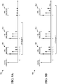
- FIG. 1A is a diagram illustrating an LTE network architecture 100.
- the LTE network architecture 100 may be referred to as an Evolved Packet System (EPS) 100.
- the EPS 100 may include one or more UE 102, an Evolved UMTS Terrestrial Radio Access Network (E-UTRAN) 104, an Evolved Packet Core (EPC) 110, a Home Subscriber Server (HSS) 120, and an Operator's Internet Protocol (IP) Services 122.
- the EPS can interconnect with other access networks, but for simplicity those entities/interfaces are not shown.
- the EPS provides packet-switched services, however, as those skilled in the art will readily appreciate, the various concepts presented throughout this disclosure may be extended to networks providing circuit-switched services.
- the E-UTRAN includes the eNB 106 and other eNBs 108.
- the eNB 106 provides user and control planes protocol terminations toward the UE 102.
- the eNB 106 may be connected to the other eNBs 108 via a backhaul (e.g., an X2 interface).
- the eNB 106 may also be referred to as a base station, a Node B, an access point, a base transceiver station, a radio base station, a radio transceiver, a transceiver function, a basic service set (BSS), an extended service set (ESS), or some other suitable terminology.
- the eNB 106 provides an access point to the EPC 110 for a UE 102.
- Examples of UEs 102 include a cellular phone, a smart phone, a session initiation protocol (SIP) phone, a laptop, a personal digital assistant (PDA), a satellite radio, a global positioning system, a multimedia device, a video device, a digital audio player (e.g., MP3 player), a camera, a game console, a tablet, or any other similar functioning device.
- SIP session initiation protocol
- PDA personal digital assistant
- satellite radio a global positioning system
- multimedia device e.g., a digital audio player (e.g., MP3 player), a camera, a game console, a tablet, or any other similar functioning device.
- MP3 player digital audio player
- the UE 102 may also be referred to by those skilled in the art as a mobile station, a subscriber station, a mobile unit, a subscriber unit, a wireless unit, a remote unit, a mobile device, a wireless device, a wireless communications device, a remote device, a mobile subscriber station, an access terminal, a mobile terminal, a wireless terminal, a remote terminal, a handset, a user agent, a mobile client, a client, or some other suitable terminology.
- the eNB 106 is connected to the EPC 110.
- the EPC 110 includes a Mobility Management Entity (MME) 112, other MMEs 114, a Serving Gateway 116, and a Packet Data Network (PDN) Gateway 118.
- MME Mobility Management Entity
- PDN Packet Data Network
- the MME 112 is the control node that processes the signaling between the UE 102 and the EPC 110.
- the MME 112 provides bearer and connection management. All user IP packets are transferred through the Serving Gateway 116, which itself is connected to the PDN Gateway 118.
- the PDN Gateway 118 provides UE IP address allocation as well as other functions.
- the PDN Gateway 118 is connected to the Operator's IP Services 122.
- the Operator's IP Services 122 may include the Internet, the Intranet, an IP Multimedia Subsystem (IMS), and a PS Streaming Service (PSS).
- IMS IP Multimedia Subsystem
- PSS PS Streaming Service
- Broadcast/Multicast Service Center (BM-SC) 126 may serve as a portal or entry point for content providers and may provide certain authorization and other services.
- Broadcast/Multicast Management Entity (BME) 124 may be configured to receive, process, and/or forward control signaling, and may be used to select an eNB 106 or 108 to receive MBMS control signaling.
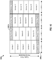
- FIG. 1B illustrates functional entities of a wireless communication system 124 for providing or supporting MBSFN service.
- the system 124 uses a Guaranteed Bit Rate (GBR) type MBMS bearer, wherein the Maximum Bit Rate (MBR) equals the GBR.
- GBR Guaranteed Bit Rate
- MBR Maximum Bit Rate
- the system 124 may include an MBMS Gate Way (MBMS GW) 140.
- the MBMS GW 140 controls Internet Protocol (IP) multicast distribution of MBMS user plane data to eNodeBs 128 via an M1 interface; one eNB 128 of many possible eNBs is shown.
- IP Internet Protocol
- the MBMS GW controls IP multicast distribution of MBMS user plane data to UTRAN Radio Network Controllers (RNCs) 144 via an M1 interface; one UTRAN RNC 144 of many possible RNCs is shown.
- RNCs Radio Network Controllers
- the M1 interface is associated to MBMS data (user plane) and makes use of IP for delivery of data packets.
- the eNB 128 may provide MBMS content to a user equipment (UE)/mobile entity 126 via an E-UTRAN Uu interface.
- the RNC 144 may provide MBMS content to a UE mobile entity 146 via a Uu interface.
- the MBMS GW 140 may further perform MBMS Session Control Signaling, for example MBMS session start and session stop, via the Mobility Management Entity (MME) 132 and Sm interface.
- MME Mobility Management Entity
- the MBMS GW 140 may further provide an interface for entities using MBMS bearers through the SG-mb (user plane) reference point, and provide an interface for entities using MBMS bearers through the SGi-mb (control plane) reference point.
- the SG-mb Interface carries MBMS bearer service specific signaling.
- the SGi-mb interface is a user plane interface for MBMS data delivery.
- MBMS data delivery may be performed by IP unicast transmission, which may be a default mode, or by IP multicasting.
- the MBMS GW 140 may provide a control plane function for MBMS over UTRAN via a Serving General Packet Radio Service Support Node (SGSN) 142 and the Sn/Iu interfaces.
- SGSN Serving General Packet Radio Service Support Node
- the system 124 may further include a Multicast Coordinating Entity (MCE) 130.
- the MCE 130 may perform an admission control function form MBMS content, and allocate time and frequency radio resources used by all eNBs in the MBSFN area for multi-cell MBMS transmissions using MBSFN operation.
- the MCE 130 may determine a radio configuration for an MBSFN Area, such as, for example, the modulation and coding scheme.
- the MCE 130 may schedules and control user plane transmission of MBMS content, and manage eMBMS service multiplexing, by determining which services are to be multiplexed in which Multicast Channel (MCH).
- MCH Multicast Channel
- the MCE 130 may participate in MBMS Session Control Signaling with the MME 132 through an M3 interface, and may provide a control plane interface M2 with the eNB 128.
- the system 124 may further include a Broadcast-Multicast Service Center (BM-SC) 136 in communication with a content provider server 138.
- the BM-SC 136 may handle intake of multicast content from one or more sources such as the content provider 138, and provide other higher-level management functions as described below. These functions may include, for example, a membership function, including authorization and initiation of MBMS services for an identified UE.
- the BM-SC 136 may further perform MBMS session and transmission functions, scheduling of live broadcasts, and delivery, including MBMS and associated delivery functions.
- the BM-SC 140 may further provide service advertisement and description, such as advertising content available for multicast.
- a separate Packet Data Protocol (PDP) context may be used to carry control messages between UE and BM-SC.
- PDP Packet Data Protocol
- the BM-SC may further provide security functions such as key management, manage charging of content providers according to parameters such as data volume and QoS, provide content synchronization for MBMS in UTRAN and in E-UTRAN for broadcast mode, and provide header compression for MBSFN data in UTRAN.
- the BM-SC 136 may indicate session start, update and stop to the MBMS-GW 140 including session attributes such as QoS and MBMS service area.
- the system 124 may further include a Multicast Management Entity (MME) 132 in communication with the MCE 130 and MBMS-GW 140.
- MME Multicast Management Entity
- the MME 124 may provide a control plane function for MBMS over E-UTRAN.
- the MME may provide the eNB 128, 144 with multicast related information defined by the MBMS-GW 140.
- An Sm interface between the MME 132 and the MBMS-GW 140 may be used to carry MBMS control signaling, for example, session start and stop signals.
- the system 124 may further include a Packet Data Network (PDN) Gate Way (GW) 134, sometimes abbreviated as a P-GW.
- PDN Packet Data Network
- GW Gate Way
- the P-GW 134 may provide an Evolved Packet System (EPS) bearer between the UE 126 and BM-SC 136 for signaling and/or user data.
- EPS Evolved Packet System
- the P-GW may receive Uniform Resource Locator (URL) based requests originating from UEs in association with IP addresses assigned to the UEs.
- the BM-SC 136 may also be linked to one or more content providers via the P-GW 134, which may communicate with the BM-SC 136 via an IP interface.
- FIG. 2 is a diagram illustrating an example of an access network 200 in an LTE network architecture.
- the access network 200 is divided into a number of cellular regions (cells) 202.
- One or more lower power class eNBs 208 may have cellular regions 210 that overlap with one or more of the cells 202.
- the lower power class eNB 208 may be a femto cell (e.g., home eNB (HeNB)), pico cell, micro cell, or remote radio head (RRH).
- HeNB home eNB
- RRH remote radio head
- the macro eNBs 204 are each assigned to a respective cell 202 and are configured to provide an access point to the EPC 110 for all the UEs 206 in the cells 202.
- the eNBs 204 are responsible for all radio related functions including radio bearer control, admission control, mobility control, scheduling, security, and connectivity to the serving gateway 116.
- the modulation and multiple access scheme employed by the access network 200 may vary depending on the particular telecommunications standard being deployed.
- OFDM is used on the DL
- SC-FDMA is used on the UL to support both frequency division duplex (FDD) and time division duplex (TDD).
- FDD frequency division duplex
- TDD time division duplex
- FDD frequency division duplex
- TDD time division duplex
- EV-DO Evolution-Data Optimized
- UMB Ultra Mobile Broadband
- EV-DO and UMB are air interface standards promulgated by the 3rd Generation Partnership Project 2 (3GPP2) as part of the CDMA2000 family of standards and employs CDMA to provide broadband Internet access to mobile stations. These concepts may also be extended to Universal Terrestrial Radio Access (UTRA) employing Wideband-CDMA (W-CDMA) and other variants of CDMA, such as TD-SCDMA; Global System for Mobile Communications (GSM) employing TDMA; and Evolved UTRA (E-UTRA), IEEE 802.11 (Wi-Fi), IEEE 802.16 (WiMAX), IEEE 802.20, and Flash-OFDM employing OFDMA.
- UTRA, E-UTRA, UMTS, LTE and GSM are described in documents from the 3GPP organization.
- CDMA2000 and UMB are described in documents from the 3GPP2 organization. The actual wireless communication standard and the multiple access technology employed will depend on the specific application and the overall design constraints imposed on the system.
- the eNBs 204 may have multiple antennas supporting MIMO technology.
- MIMO technology enables the eNBs 204 to exploit the spatial domain to support spatial multiplexing, beamforming, and transmit diversity.
- Spatial multiplexing may be used to transmit different streams of data simultaneously on the same frequency.
- the data streams may be transmitted to a single UE 206 to increase the data rate or to multiple UEs 206 to increase the overall system capacity. This is achieved by spatially precoding each data stream (i.e., applying a scaling of an amplitude and a phase) and then transmitting each spatially precoded stream through multiple transmit antennas on the DL.
- the spatially precoded data streams arrive at the UE(s) 206 with different spatial signatures, which enables each of the UE(s) 206 to recover the one or more data streams destined for that UE 206.
- each UE 206 transmits a spatially precoded data stream, which enables the eNB 204 to identify the source of each spatially precoded data stream.
- Beamforming may be used to focus the transmission energy in one or more directions. This may be achieved by spatially precoding the data for transmission through multiple antennas. To achieve good coverage at the edges of the cell, a single stream beamforming transmission may be used in combination with transmit diversity.
- OFDM is a spread-spectrum technique that modulates data over a number of subcarriers within an OFDMA symbol.
- the subcarriers are spaced apart at precise frequencies. The spacing provides "orthogonality" that enables a receiver to recover the data from the subcarriers.
- a guard interval such as a CP may be added to each OFDMA symbol to combat inter-OFDM-symbol interference.
- the UL may use SC-FDMA in the form of a DFT-spread OFDM signal to compensate for high peak-to-average power ratio (PAPR).
- PAPR peak-to-average power ratio
- FIG. 3 is a diagram 300 illustrating an example of a DL frame structure in LTE.
- a frame (10 ms) may be divided into 10 equally sized subframes. Each subframe may include two consecutive time slots.
- a resource grid may be used to represent two time slots, each time slot including a resource block.
- the resource grid is divided into multiple resource elements.
- a resource block contains 12 consecutive subcarriers in the frequency domain and, for a normal CP in each OFDMA symbol, 7 consecutive OFDMA symbols in the time domain, or 84 resource elements.
- a resource block contains 6 consecutive OFDMA symbols in the time domain and has 72 resource elements.
- Some of the resource elements, as indicated as R 302, 304, include DL reference signals (DL-RS).
- DL-RS DL reference signals
- the DL-RS include Cell-specific RS (CRS) (also sometimes called common RS) 302 and UE-specific RS (UE-RS) 304.
- UE-RS 304 are transmitted only on the resource blocks upon which the corresponding physical DL shared channel (PDSCH) is mapped.
- PDSCH physical DL shared channel
- the number of bits carried by each resource element depends on the modulation scheme. Thus, the more resource blocks that a UE receives and the higher the modulation scheme, the higher the data rate for the UE.
- FIG. 4 is a diagram 400 illustrating an example of an UL frame structure in LTE.
- the available resource blocks for the UL may be partitioned into a data section and a control section.
- the control section may be formed at the two edges of the system bandwidth and may have a configurable size.
- the resource blocks in the control section may be assigned to UEs for transmission of control information.
- the data section may include all resource blocks not included in the control section.
- the UL frame structure results in the data section including contiguous subcarriers, which may allow a single UE to be assigned all of the contiguous subcarriers in the data section.
- a UE may be assigned resource blocks 410a, 410b in the control section to transmit control information to an eNB.
- the UE may also be assigned resource blocks 420a, 420b in the data section to transmit data to the eNB.
- the UE may transmit control information in a physical UL control channel (PUCCH) on the assigned resource blocks in the control section.
- the UE may transmit only data or both data and control information in a physical UL shared channel (PUSCH) on the assigned resource blocks in the data section.
- a UL transmission may span both slots of a subframe and may hop across frequency.
- a set of resource blocks may be used to perform initial system access and achieve UL synchronization in a physical random access channel (PRACH) 430.
- the PRACH 430 carries a random sequence and cannot carry any UL data/signaling.
- Each random access preamble occupies a bandwidth corresponding to six consecutive resource blocks.
- the starting frequency is specified by the network. That is, the transmission of the random access preamble is restricted to certain time and frequency resources. There is no frequency hopping for the PRACH.
- the PRACH attempt is carried in a single subframe (1 ms) or in a sequence of few contiguous subframes and a UE can make only a single PRACH attempt per frame (10 ms).
- FIG. 5 is a diagram 500 illustrating an example of a radio protocol architecture for the user and control planes in LTE.
- the radio protocol architecture for the UE and the eNB is shown with three layers: Layer 1, Layer 2, and Layer 3.
- Layer 1 (L1 layer) is the lowest layer and implements various physical layer signal processing functions.
- the L1 layer will be referred to herein as the physical layer 506.
- Layer 2 (L2 layer) 508 is above the physical layer 506 and is responsible for the link between the UE and eNB over the physical layer 506.
- the L2 layer 508 includes a media access control (MAC) sublayer 510, a radio link control (RLC) sublayer 512, and a packet data convergence protocol (PDCP) 514 sublayer, which are terminated at the eNB on the network side.
- MAC media access control
- RLC radio link control
- PDCP packet data convergence protocol
- the UE may have several upper layers above the L2 layer 508 including a network layer (e.g., IP layer) that is terminated at the PDN gateway 118 on the network side, and an application layer that is terminated at the other end of the connection (e.g., far end UE, server, etc.).
- IP layer e.g., IP layer
- the PDCP sublayer 514 provides multiplexing between different radio bearers and logical channels.
- the PDCP sublayer 514 also provides header compression for upper layer data packets to reduce radio transmission overhead, security by ciphering the data packets, and handover support for UEs between eNBs.
- the RLC sublayer 512 provides segmentation and reassembly of upper layer data packets, retransmission of lost data packets, and reordering of data packets to compensate for out-of-order reception due to hybrid automatic repeat request (HARQ).
- HARQ hybrid automatic repeat request
- the MAC sublayer 510 provides multiplexing between logical and transport channels.
- the MAC sublayer 510 is also responsible for allocating the various radio resources (e.g., resource blocks) in one cell among the UEs.
- the MAC sublayer 510 is also responsible for HARQ operations.
- the radio protocol architecture for the UE and eNB is substantially the same for the physical layer 506 and the L2 layer 508 with the exception that there is no header compression function for the control plane.
- the control plane also includes a radio resource control (RRC) sublayer 516 in Layer 3 (L3 layer).
- RRC sublayer 516 is responsible for obtaining radio resources (i.e., radio bearers) and for configuring the lower layers using RRC signaling between the eNB and the UE.
- FIG. 6 is a block diagram of an eNB 610 in communication with a UE 650 in an access network.
- upper layer packets from the core network are provided to a controller/processor 675.
- the controller/processor 675 implements the functionality of the L2 layer.
- the controller/processor 675 provides header compression, ciphering, packet segmentation and reordering, multiplexing between logical and transport channels, and radio resource allocations to the UE 650 based on various priority metrics.
- the controller/processor 675 is also responsible for HARQ operations, retransmission of lost packets, and signaling to the UE 650.
- the transmit (TX) processor 616 implements various signal processing functions for the L1 layer (i.e., physical layer).
- the signal processing functions include coding and interleaving to facilitate forward error correction (FEC) at the UE 650 and mapping to signal constellations based on various modulation schemes (e.g., binary phase-shift keying (BPSK), quadrature phase-shift keying (QPSK), M-phase-shift keying (M-PSK), M-quadrature amplitude modulation (M-QAM)).
- FEC forward error correction
- BPSK binary phase-shift keying
- QPSK quadrature phase-shift keying
- M-PSK M-phase-shift keying
- M-QAM M-quadrature amplitude modulation
- Each stream is then mapped to an OFDM subcarrier, multiplexed with a reference signal (e.g., pilot) in the time and/or frequency domain, and then combined together using an Inverse Fast Fourier Transform (IFFT) to produce a physical channel carrying a time domain OFDMA symbol stream.
- the OFDM stream is spatially precoded to produce multiple spatial streams.
- Channel estimates from a channel estimator 674 may be used to determine the coding and modulation scheme, as well as for spatial processing.
- the channel estimate may be derived from a reference signal and/or channel condition feedback transmitted by the UE 650.
- Each spatial stream may then provide to a different antenna 620 via a separate transmitter 618TX.
- Each transmitter 618TX may modulate an RF carrier with a respective spatial stream for transmission.
- each receiver 654RX receives a signal through its respective antenna 652.
- Each receiver 654RX recovers information modulated onto an RF carrier and provides the information to the receive (RX) processor 656.
- the RX processor 656 implements various signal processing functions of the L1 layer.
- the RX processor 656 may perform spatial processing on the information to recover any spatial streams destined for the UE 650. If multiple spatial streams are destined for the UE 650, they may be combined by the RX processor 656 into a single OFDMA symbol stream.
- the RX processor 656 then converts the OFDMA symbol stream from the time-domain to the frequency domain using a Fast Fourier Transform (FFT).
- FFT Fast Fourier Transform
- the frequency domain signal comprises a separate OFDMA symbol stream for each subcarrier of the OFDM signal.
- the symbols on each subcarrier, and the reference signal, are recovered and demodulated by determining the most likely signal constellation points transmitted by the eNB 610. These soft decisions may be based on channel estimates computed by the channel estimator 658.
- the soft decisions are then decoded and deinterleaved to recover the data and control signals that were originally transmitted by the eNB 610 on the physical channel.
- the data and control signals are then provided to the controller/processor 659.
- the controller/processor 659 implements the L2 layer.
- the controller/processor can be associated with a memory 660 that stores program codes and data.
- the memory 660 may be referred to as a computer-readable medium.
- the controller/processor 659 provides demultiplexing between transport and logical channels, packet reassembly, deciphering, header decompression, control signal processing to recover upper layer packets from the core network.
- the upper layer packets are then provided to a data sink 662, which represents all the protocol layers above the L2 layer.
- Various control signals may also be provided to the data sink 662 for L3 processing.
- the controller/processor 659 is also responsible for error detection using an acknowledgement (ACK) and/or negative acknowledgement (NACK) protocol to support HARQ operations.
- ACK acknowledgement
- NACK negative acknowledgement
- a data source 667 is used to provide upper layer packets to the controller/processor 659.
- the data source 667 represents all protocol layers above the L2 layer.
- the controller/processor 659 implements the L2 layer for the user plane and the control plane by providing header compression, ciphering, packet segmentation and reordering, and multiplexing between logical and transport channels based on radio resource allocations by the eNB 610.
- the controller/processor 659 is also responsible for HARQ operations, retransmission of lost packets, and signaling to the eNB 610.
- Channel estimates derived by a channel estimator 658 from a reference signal or feedback transmitted by the eNB 610 may be used by the TX processor 668 to select the appropriate coding and modulation schemes, and to facilitate spatial processing.
- the spatial streams generated by the TX processor 668 may be provided to different antenna 652 via separate transmitters 654TX. Each transmitter 654TX may modulate an RF carrier with a respective spatial stream for transmission.
- the UL transmission is processed at the eNB 610 in a manner similar to that described in connection with the receiver function at the UE 650.
- Each receiver 618RX receives a signal through its respective antenna 620.
- Each receiver 618RX recovers information modulated onto an RF carrier and provides the information to a RX processor 670.
- the RX processor 670 may implement the L1 layer.
- the controller/processor 675 implements the L2 layer.
- the controller/processor 675 can be associated with a memorv 676 that stores program codes and data.
- the memory 676 may be referred to as a computer-readable medium.
- the control/processor 675 provides demultiplexing between transport and logical channels, packet reassembly, deciphering, header decompression, control signal processing to recover upper layer packets from the UE 650.
- Upper layer packets from the controller/processor 675 may be provided to the core network.
- the controller/processor 675 is also responsible for error detection using an ACK and/or NACK protocol to support HARQ operations.
- FIG. 7 is a diagram 750 illustrating evolved Multicast Broadcast Multimedia Service (eMBMS) in an MBSFN.
- the eNBs 752 in cells 752' may form a first MBSFN area and the eNBs 754 in cells 754' may form a second MBSFN area.
- the eNBs 752, 754 may be associated with other MBSFN areas, for example, up to a total of eight MBSFN areas.
- a cell within an MBSFN area may be designated a reserved cell. Reserved cells do not provide multicast/broadcast content, but are time-synchronized to the cells 752', 754' and have restricted power on MBSFN resources in order to limit interference to the MBSFN areas.
- Each eNB in an MBSFN area synchronously transmits the same eMBMS control information and data in a synchronized manner.
- Each area may support broadcast, multicast, and unicast services.
- a unicast service is a service intended for a specific user, e.g., a voice call.
- a multicast service is a service that may be received by a group of users, e.g., a subscription video service.
- a broadcast service is a service that may be received by all users, e.g., a news broadcast.
- the first MBSFN area may support a first eMBMS broadcast service, such as by providing a particular news broadcast to UE 770.
- the second MBSFN area may support a second eMBMS broadcast service, such as by providing a different news broadcast to UE 760.
- Each MBSFN area supports a plurality of physical multicast channels (PMCH) (e.g., 15 PMCHs).
- PMCH corresponds to a multicast channel (MCH).
- MCH multicast channel
- Each MCH can multiplex a plurality (e.g., 29) of multicast logical channels.
- Each MBSFN area may have one multicast control channel (MCCH).
- MCCH multicast control channel
- one MCH may multiplex one MCCH and a plurality of multicast traffic channels (MTCHs) and the remaining MCHs may multiplex a plurality of MTCHs.
- MTCHs multicast traffic channels
- FIG. 8 is diagram illustrating example scenarios 800 and 840 that may give rise to inter-symbol interference.
- FIG. 8 also includes a timing chart 820 illustrating the effect of propagation delays, as observed at UE 804.
- Example scenario 800 relates to a single eNB 802 that communicates with UE 804.
- a symbol 822 received at UE 804 from eNB 802 travels by a direct propagation path 808 and a delayed version of symbol 822 arrives as delayed symbol 828 from a longer, indirect propagation path 810 created, for example, by a reflection at object 806, which may be a building. If the difference in time of arrival 832 of symbol 822 and time of arrival 834 of delayed symbol 828 is less than the CP duration, then no inter-symbol interference occurs and symbols 822 and 828 may be combined at the UE 804. In the depicted example, the duration of CP 824 is long enough to prevent inter-symbol interference between delayed symbol 828, which ends at time 830, and next symbol 826.
- the difference between the time of arrival 832 of symbol 822 at UE 804 through direct path 808 and the time of arrival 834 of delayed symbol 828 at UE 804 may be referred to as the delay spread of scenario 800, particularly where indirect path 810 is the longest indirect propagation path available between eNB 802 and UE 804.
- An indirect path may have the longest propagation path length and/or delay associated with eNB 802 and UE 804.
- Timing chart 820 may also be representative of an eMBMS scenario 840 in which eNB 842 and eNB 846 may be located at significantly different distances from UE 844 or may transmit along one or more propagation paths that have significantly different lengths.
- symbol 822 and delayed symbol 828 which are transmitted in a synchronous manner by eNBs 842 and 846 respectively, may arrive at different times at UE 844.
- inter-symbol interference may be averted if the end of delayed symbol 828 occurs during the duration of CP 824 of the next symbol 826 received at the UE 844.
- Symbols 822 and 828 arriving by different propagation paths may be combined at the UE 804 if the delay spread between the symbols 822 and 828 is less than the CP duration.
- the difference between the time of arrival 832 of symbol 822 at UE 844 by shortest propagation path (here, nearby eNB 842) and the time of arrival 834 of symbol 828 from distant eNB 846 at UE 844 may be referred to as the delay spread of eMBMS scenario 840.
- the delay spread for eMBMS scenario 840 is typically calculated using the arrival time 832 associated with the shortest propagation path length between an eNB 842 or 846 and UE 844, which may correspond to the direct path 808 from the closest eNB 842, and the arrival time 834 associated with the longest propagation path length between an eNB 842 or 846 and UE 844, which may correspond to the longest indirect path 810 in the MBSFN area, typically from the most distant eNB 846.
- the longest propagation path length may also be associated with an eNB 846 that is closer than a more distant eNB 846 when a longer indirect propagation path exists between closer eNB 842 and UE 844.
- LTE defines an extended CP that may be used for eMBMS instead of a normal CP, particularly when an MBSFN area comprises large cells that produce correspondingly large delay spread.
- the duration of the extended CP may be 16.7 ⁇ s for LTE, whereas the duration of the normal CP may be 4.7 or 5.1 ⁇ s, for example.
- the CP 824 may be required to cover timing differences of transmissions received from different eNBs 842, 846 in an MBSFN.
- a UE 844 in an MBSFN may receive signals from a nearby eNB 842 that has transmission power in the range of 10 to 40 watts and from a distant eNB 846 that has a higher transmission power, e.g.
- a longer CP duration may be used to allow signals from both eNBs 842 and 846 to be combined and to avoid inter-symbol interference related longer propagation paths between UE 844 and distant eNBs 846 with high transmission power.
- a CP duration may be used that is at least two or three times longer than the extended CP duration.
- CP duration as a percentage of the time required to transmit a symbol and the CP may be referred to as CP overhead.
- Some embodiments may increase symbol duration to compensate for effects of increased CP duration, which may include increased CP overhead.
- FIGS. 9A and 9B illustrate delay spreads in an MBSFN area in more detail.
- FIGS. 9A and 9B relate to an exemplary MBSFN area in which three eNBs transmit the same signal information to a UE in a synchronized manner, at a time t 0 .
- timing chart 900 multiple signals are received by a UE from each of the eNBs.
- a first group of signals 902 is received at the UE from a first eNB, with the first signal in group 902 arriving at time t 1
- a second group of signals 904 is received at the UE from a second eNB, with the first signal in group 904 arriving at time t 2
- a third group of signals 906 is received from a third eNB, with the first signal in group 906 arriving at time t 3 .
- the signals in each group 902, 904, and 906 may arrive at the UE at different times and the time elapsed between t 0 and the arrival of the first signal of each group 902, 904 and 906, t 1 , t 2 , and t 3 respectively, may represent the minimum propagation delay for the groups 902, 904 and 906.
- Minimum propagation delay may correspond to the shortest propagation path between an eNB and a UE.
- Timing chart 900 further illustrates that the signal transmitted by each eNB may arrive at different times at the UE because of differences in the lengths of the propagation paths between each eNB and the UE.
- delayed versions of the signal may arrive at times t 1 + x , t 1 + y , and t 1 + z .
- the time elapsed between t 1 and t 1 + z may represent the delay spread associated with the first eNB, corresponding to different propagation paths between the first eNB and the UE.
- Each propagation path between an eNB and a UE may have an attenuation that is the same or different from other propagation paths between the eNB and the UE.
- the first signal of group 902 is the first signal received by the UE ( t 1 ).
- the UE may integrate or combine one or more signals received from one or more eNBs. Signals that are delayed with respect to time t 1 by less than the length of the duration of CP 1 may be combined at the UE.
- CP 1 is the CP defined for the MBSFN of FIG. 9A . Signals that are delayed for longer than the duration of CP 1 may cause inter-symbol interference.
- the signals in group 906 are shown as being attenuated to a level that is close to channel noise level and these attenuated signals may not cause significant inter-symbol interference or contribute significantly to MSFN gain as seen by the UE.
- CP 1 may have a duration that is less than the relative propagation delay between groups 902 and 906 (i.e. t 3 -t 1 ) and consequently, the signals of group 906 may not be coherently combined with the signals received from the first and second eNBs at the UE.
- the signals of group 906 received from the third eNB have the longest propagation delays in the illustrated MBSFN and are also most attenuated.
- CP length may be configured to be less than a relative propagation delay of a signal received at the UE where the relative propagation delay corresponds to a propagation path length at which the attenuation of the signal is not expected to cause significant inter-symbol interference or contribute significantly to MSFN channel gain seen at the UE.
- the signals of group 906 are significantly attenuated and can be excluded from coherent combination at the UE when CP 1 is used.
- FIG. 9B illustrates the delay spreads and attenuation for the first, second, and third eNBs in which power level of the signals received from the third eNB (group 906') are comparable to the power levels of at least some signals in the groups 902 and 904, which are received from the first and second eNBs.
- This parity in received signal power may be the result of an increased transmitter power output from the third eNB relative to the power output of the first and second eNBs.
- the increased power of the signals in group 906' may cause significant inter-symbol interference when CP length is insufficiently long to cover the propagation delays of significant signals in group 906'.
- a longer CP duration may be configured for the MBSFN (CP 2) to cover the propagation delays of the signals in group 906' received from the third eNB, and thereby permit the signals of group 906' to be coherently combined with the signals received from the first and second eNBs to provide MBSFN gain at the UE.
- Specific broadcast use cases in various terrestrial broadcast systems may be served by a derivative form of LTE Broadcast/eMBMS.
- these use cases may benefit from a cyclic prefix that is longer than those nominally available in the existing LTE specification, such as regular and extended cyclic prefixes.
- the first use case considered provides a low power, low tower height, mobile, single frequency network (SFN) network.
- This use case defines a typical LTE Broadcast application, which may support tablets and smartphones, whether indoors, outdoors, or vehicular.
- Low power typically refers to a network that has transmitter sites in the range of 2kW effective isotropic radiated power (EIRP) per 5 MHz.
- EIRP effective isotropic radiated power
- Low tower typically refers to a radiation height in the range of 30 m
- mobile typically refers to a network type that supports all classes of service for which the receiving antenna is not stationary.
- the applicable range of Doppler velocity is generally 3 km/hr to 200 km/hr for ATSC.
- the currently defined 16.66 and 33.33 ⁇ s cyclic prefixes should be sufficient in both mixed and dedicated carrier modes.
- This selection of cyclic prefixes may be duplicated in any standalone mode.
- This deployment style may also be suitable for indoor reception by nominally fixed receivers.
- the high Doppler rate is generally not required for this use case, however the low speed Doppler may be beneficial.
- the appropriate channel model for such reception is a multipath Rayleigh fading model. Indoor reception is likely dominated by close-in reflections in a temporal sense. Given that this use case is dominated by a Rayleigh fading dominated channel models, there may be significant efficiency gain possible due to the use of MIMO.
- the potential benefits of MIMO here depend on the deployment style of the network.
- This deployment style is Single Frequency Network (SFN).
- SFN Single Frequency Network
- the frequency reuse in such deployments is 100% and the bits per second (bps)/Hz of the deployment is less than or equal to two bps/Hz, although the selection of modulation coding scheme (MCS) may ultimately be determined by the site density and the total number of sites within a multicast broadcast multimedia service SFN (MBSFN) area.
- MCS modulation coding scheme
- MBSFN multicast broadcast multimedia service SFN
- Medium power typically refers to transmitter with a maximum radiated power of 50 kW effective radiated power (ERP), and high tower typically refers to a transmit radiation height above 200 m.
- ERP effective radiated power
- This deployment style is a potential ATSC/LTE Broadcast application that may support tablets and smartphones, whether indoors, outdoors or in a vehicle.
- the applicable range of Doppler velocity may generally range from 3 km/hr to 200 km/hr.
- This deployment style is also potentially suitable for indoor reception by nominally fixed receivers.
- a high Doppler rate is generally not required for this use case, however the low speed Doppler may be beneficial.
- the appropriate channel model for such reception may also be a multipath Rayleigh fading model.
- the LTE Broadcast physical layer has limitations for application to this use case, such that the existing cyclic prefixes may not be long enough to adequately guard against the long differential delays.
- the presence of high transmit towers in the network may lead to such long differential delays, in which cyclic prefixes of more than a 90 ⁇ s may be beneficial.
- FIG. 1 Another use case considered provides a high power, high tower, multi-frequency network (MFN), with roof top reception.
- Roof top reception generally refers to the receiving antenna being stationary and at a receiving height in the range of between 9 and 10 m.
- This type of deployment style is also a potential ATSC/LTE Broadcast application that supports roof top reception for consumption with nominally fixed receivers.
- the currently defined channel model is an additive white Gaussian noise (AWGN)-based model, although it is known that a Ricean model may also be useful for defining the appropriate channel in this use case.
- the duration of the channel for this style of deployment is typically less than 30 ⁇ s for the 99 th percentile reception locations. However, there are known cases of paths up to 100 ⁇ s.
- cyclic prefix durations greater than 100 ⁇ s, in order to support this use case.
- This dimension of cyclic prefix may also support medium power SFN within the high power footprint, e.g., in geographically shadowed areas.
- the ATSC target efficiency is currently defined at 4.2 bps/Hz at 15 dB carrier-to-noise (C/N) for AWGN channels.
- the pilot overhead should be decreased, as compared to the mobile profile. This combination of high bps per Hz efficiency with relatively long cyclic prefix will also result in a larger fast Fourier transform (FFT) requirement.
- FFT fast Fourier transform
- CDD Cyclic Delay Diversity
- SFBC Space-Frequency Block Code
- Another use case considered provides a low power, lower tower, SFN, roof top reception.
- This use case may not be nominally required within the context of ATSC, however, it may fall within the range of cyclic prefixes that might otherwise support other use cases.
- This use case is generally based on city/suburban coverage for indoor and vehicular handheld reception with a moderately dense deployment and roof top reception in a far more sparse rural deployment. Simulations have demonstrated that cyclic prefix durations up to 200 ⁇ s may be beneficial for the rural reception use case.
- spectral reuse As an SFN deployment style, wherein spectral reuse may approach 100%, the exact spectral reuse depends on the use of directional receive antennas with a sufficient front to back ratio in the rural border areas of the respective multicast-broadcast single frequency networks (MBSFNs). Interior areas of the SFN may utilize omni-directional antennas. An MBSFN transition within suburban areas may use similar considerations of interference as in the previous low power, low tower use case.
- MBSFNs multicast-broadcast single frequency networks
- Some methods call for lengthening the total duration of the symbol, while otherwise leaving the general structure of LTE intact. This process may be reasonable as long as the cyclic prefix overhead remains 20% of the total duration. However, in order to achieve the transmission efficiencies that will be used with future broadcast systems, the cyclic prefix duration may need to grow while the overhead is reduced. Such aspects of the present disclosure may, therefore, employ revised numerology in both the time direction and frequency directions.
- the transmission structure of LTE is based on 1 ms subframes.
- the total duration of the symbol plus cyclic prefix can be adjusted relative to the subframe duration, which may be adjusted to allow for varying cyclic prefix durations.
- Various aspects of the present disclosure select to constrain the total transmitted duration to be in an integer relationship with respect to the subframe, whether in a fractional sense or as a multiple, as this simplifies implementation.
- the number of OFDM carriers per resource block will be proportional to the duration. See Table 1, below.
- the first two rows in Table 1 denote the already-required implementation for mixed or dedicated carrier modes. In Table 1, it is assumed that new format subframes are 100% LTE Broadcast for all added modes.
- FIG. 10 is a block diagram illustrating a conceptual statistical multiplexing 1000 across time and frequency.
- the N decoded services have to be non-blocking in the time domain. For example, the part of service 6a 1001 will not overlap in time with the other part of 6b 1002.
- This incremental decoding method for high bandwidth multiplexes may be a desirable solution for mobile services, as it limits the additional complexity in mobile devices, while enabling the medium power mobile and potentially low power, low tower roof top reception use cases.
- the supported total duration has been increased and some modes are fractional with respect to subframes. These aspects are included in signaling and the maximum FFT is increased. This is a direct consequence of the increases total duration of symbol time plus cyclic prefix. There are newly defined pilot patterns for each new total duration.
- the current maximum bps/Hz supported for mobile applications is more than 3 bps/Hz. Achieving the highest possible bps/Hz efficiency, however, instructs the use of a fixed profile, which results in reduced pilot overhead and reduced cyclic prefix duration relative to the total duration, as compared to Table 1 above.
- These high efficiency fixed modes may not be receivable in mobile applications, due to the large transforms, and narrow carrier spacing. Narrow carrier spacing significantly limits the maximum Doppler rate supportable, without Inter Carrier Interference (ICI) cancelation. ICI substantially increases device complexity. Larger transforms also impact complexity. It may be preferable that mobile requirements be met without ICI or the use of larger fixed profile transforms.
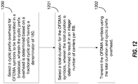
- FIG. 11 is a functional block diagram illustrating example blocks executed to implement one aspect of the present disclosure.
- a cyclic prefix overhead is selected for OFDMA symbols to be transmitted in a broadcast, wherein the cyclic prefix overhead is determined based on an integer multiple of a standard carriers-to-RBs definition.
- the broadcast may, for instance, be a multi-media broadcast.
- the integer multiple the nominal 300 carrier-to-25 RBs definition is used. Integer multiples of the 300 carrier-to-25 RBs allows for variable cyclic prefix durations at a lower overhead than the normative 20% overhead in existing systems defined according to the 300 carrier-to-25 RBs definition.
- specific combinations of carrier families may beneficially provide a linear progression of cyclic prefix overhead percentages at an N x 1.33% fractional rate, where N represents an integer multiple of the ratio of the selected combination, e.g., 370 to the normative 300 carriers.
- a cyclic prefix duration is selected for the OFDMA symbols, wherein the cyclic prefix duration is determined to result in an integer number of carriers per RB based on the integer multiple of the standard carriers-to-RBs definition.
- a sequence of cyclic prefix durations may be provided which allow for an integer number of carriers per RB considering the total duration of the cyclic prefix duration and the symbol duration. For example, with the selection of the family of 370 to 300 carriers, cyclic durations of 2.5, 5, and 10 ms may be provided which result in an integer number of carriers per RB.
- the OFDMA symbols are transmitted using the cyclic prefix duration and cyclic prefix overhead.
- Table 2 illustrates a number of selections that can meet certain terrestrial broadcast system requirements for delay spread greater than 100 ⁇ s, with some margin.
- the number of carriers relative to the nominal 300 carriers per 25 RBs would increase.
- the complexity considerations for the fixed modes may be less constraining than for mobile, although it may still be desirable to keep the FFT at less than or equal to 32K.
- the numerology may work out to be integer numbers of carriers per RB.
- Table 3 illustrates how the numerology above results in integer numbers of carriers per resource block.
- Total Duration represents the total duration including symbol time plus cyclic prefix duration in seconds
- the fractional CP is a heuristically determined fraction selected to result in an integer number of carriers per RB for a number of various total durations.
- Table 3 Total Duration(msec) Carriers/RB Carriers/RB Carriers/RB 2.5 432 438 444 5 864 876 888 10 1728 1752 1776 Ratio of Carriers to Nominal 20% CP Resource Block 360/300 365/300 370/300
- Achieving higher capacity may also include increasing spectral occupancy beyond the nominal support of 25 resource blocks per 4.5 MHz.
- the integer relationship of carriers to resource blocks simplifies this process. Because each RB is 3.6% of 5 MHz, it may be reasonable to increase the total utilization by 7.2% to 97.2% by adding two additional resource blocks for a total of 27 RBs.
- Additional, new fixed profile Modulation Coding Schemes (MCS)s may be used to achieve more than 4 bps/Hz.
- Table 3 illustrates the supported bps/Hz and minimum additional white Gaussian noise (AWGN) C/N assuming a capacity achieving code.
- AWGN white Gaussian noise
- Table 4 illustrates MCS selection for fixed service at 5 MHz. These fixed profile carrier features impact the design of the following incremental manners. There is a need for revised baseband arm filters to allow for 27 RB baseband bandwidth. There are new pilot patterns for each total duration. There is revised numerology for each fractional cyclic prefix. The maximum required FFT has been further increased relative to the enhancements for mobile described above.
- the family of solutions for fractional CP based on the denominator of 75 achieves integer carriers per RB for 2.5, 5, and 10 ms total durations.
- various aspects of the present disclosure may achieve integer carriers per RB for each integer ms in total duration between 1 and 10 ms.
- the integer carriers over this range of durations changes in steps of 0.5555%.
- FIG. 12 is a functional block diagram illustrating example blocks executed to implement one aspect of the present disclosure.
- a cyclic prefix overhead is selected for OFDMA symbols to be transmitted in a broadcast, wherein the cyclic prefix overhead is determined based on a fractional cyclic prefix having a denominator of 180.
- the specific fraction of the fractional CP for determining the cyclic prefix overhead may be selected by selecting the appropriate integer, N, multiple of the unitary fraction 1/180 (0.5555%).
- a total duration is selected for the OFDMA symbols, wherein the total duration is determined to result in an integer number of carriers per RB.
- the total duration represents the sum of the symbol duration or time and the cyclic prefix duration.
- the OFDMA symbols are transmitted using the total duration and cyclic prefix overhead.
- the broadcast may be a standard system broadcast, or it may also by a multi-media broadcast.
- the present disclosure is not limited to a particular type of broadcast for the cyclic prefix overhead transmission.
- Table 5 illustrates the per RB carrier count resulting from various aspects of the present disclosure utilizing the family of solutions driven by the integer multiple of the 1/180 fraction according to Equation (1).
- Table 5 Total Duration (ms) N Fractional CP Carrier per RB Total Duration (ms) N Fractional CP Carrier per RB 1 1 0.56% 179 1 3 1.67% 177 2 1 0.56% 358 2 3 1.67% 354 3 1 0.56% 537 3 3 3 1.67% 531 4 1 0.56% 716 4 3 1.67% 708 5 1 0.56% 895 5 3 1.67% 885 6 1 0.56% 1074 6 3 1.67% 1062 7 1 0.56% 1253 7 3 1.67% 1239 8 1 0.56% 1432 8 3 1.67% 1416 9 1 0.56% 1611 9 3 1.67% 1593 10 1 0.56% 1790 10 3 1.67% 1770 1 2 1.11% 178 1 4 2.22% 176 2 2 1.11% 356 2 4 2.22% 352 3 2 1.11%
- the use of 256 quadrature amplitude modulation may be adopted for unicast transmission in LTE. This would open up an opportunity to utilize 256 QAM for LTE Broadcast applications.
- the availability of 256 QAM may not, however, provide any material benefit with respect to meeting a high bps/Hz requirement at 15 dB C/N, because 15 dB may be too low to be efficiently utilized.
- the introduction of 256 QAM in the LTE device infrastructure may, however, be beneficial from the perspective that the signal to noise limit imposed by the ADCs utilized in the device may have to improve significantly.
- LTE Broadcast will benefit from the presence of 256 QAM unicast independent of whether 256 QAM modes are adopted for LTE Broadcast. Support for 256 QAM LTE Broadcast modes may be possible based on the numerology described above for 64 QAM.
- the existing primary synchronization signal (PSS)/secondary synchronization signal (SSS)/physical broadcast channel (PBCH)/system information block (SIB) transmission format may be sufficient to describe the added physical layers features. Only one SIB may be needed to carry all such information. Semi-static SIB scheduling linked to transmit band may be applied. In the use cases discussed here either 5 or 6 MHz, although each frequency segment should describe the traffic in all frequency segments of the multiplex. Different MBSFN areas may support different cyclic prefix lengths and such information is indicated in SIB Different subframe structure is introduced for each different cyclic prefix length.
- DSP digital signal processor
- ASIC application specific integrated circuit
- FPGA field programmable gate array
- a general-purpose processor may be a microprocessor, but in the alternative, the processor may be any conventional processor, controller, microcontroller, or state machine.
- a processor may also be implemented as a combination of computing devices, e.g., a combination of a DSP and a microprocessor, a plurality of microprocessors, one or more microprocessors in conjunction with a DSP core, or any other such configuration.
- a software module may reside in RAM memory, flash memory, ROM memory, EPROM memory, EEPROM memory, registers, hard disk, a removable disk, a CD-ROM, or any other form of storage medium known in the art.
- An exemplary storage medium is coupled to the processor such that the processor can read information from, and write information to, the storage medium.
- the storage medium may be integral to the processor.
- the processor and the storage medium may reside in an ASIC.
- the ASIC may reside in a user terminal.
- the processor and the storage medium may reside as discrete components in a user terminal.
- the functions described may be implemented in hardware, software, firmware, or any combination thereof. If implemented in software, the functions may be stored on or transmitted over as one or more instructions or code on a computer-readable medium.
- a computer-readable storage medium may be any available media that can be accessed by a general purpose or special purpose computer.
- such computer-readable storage media can comprise RAM, ROM, EEPROM, CD-ROM or other optical disk storage, magnetic disk storage or other magnetic storage devices, or any other medium that can be used to carry or store desired program code means in the form of instructions or data structures and that can be accessed by a general-purpose or special-purpose computer, or a general-purpose or special-purpose processor.
- non-transitory connections may properly be included within the definition of computer-readable medium.
- the instructions are transmitted from a website, server, or other remote source using a coaxial cable, fiber optic cable, twisted pair, or digital subscriber line (DSL)
- the coaxial cable, fiber optic cable, twisted pair, or DSL are included in the definition of medium.
- Disk and disc includes compact disc (CD), laser disc, optical disc, digital versatile disc (DVD), floppy disk and blu-ray disc where disks usually reproduce data magnetically, while discs reproduce data optically with lasers. Combinations of the above should also be included within the scope of computer-readable media.
Landscapes
- Engineering & Computer Science (AREA)
- Signal Processing (AREA)
- Computer Networks & Wireless Communication (AREA)
- Mobile Radio Communication Systems (AREA)
- Radio Transmission System (AREA)
Applications Claiming Priority (4)
| Application Number | Priority Date | Filing Date | Title |
|---|---|---|---|
| US201361877864P | 2013-09-13 | 2013-09-13 | |
| US201361883820P | 2013-09-27 | 2013-09-27 | |
| US14/480,897 US9325552B2 (en) | 2013-09-13 | 2014-09-09 | Extended duration cyclic prefix with low overhead for LTE broadcast |
| PCT/US2014/054956 WO2015038621A1 (en) | 2013-09-13 | 2014-09-10 | Extended duration cyclic prefix with low overhead for lte broadcast |
Publications (2)
| Publication Number | Publication Date |
|---|---|
| EP3044922A1 EP3044922A1 (en) | 2016-07-20 |
| EP3044922B1 true EP3044922B1 (en) | 2020-01-01 |
Family
ID=51688400
Family Applications (1)
| Application Number | Title | Priority Date | Filing Date |
|---|---|---|---|
| EP14781980.9A Active EP3044922B1 (en) | 2013-09-13 | 2014-09-10 | Extended duration cyclic prefix with low overhead for lte broadcast |
Country Status (6)
| Country | Link |
|---|---|
| US (1) | US9325552B2 (enExample) |
| EP (1) | EP3044922B1 (enExample) |
| JP (1) | JP2016533139A (enExample) |
| KR (1) | KR102226787B1 (enExample) |
| CN (1) | CN105519066B (enExample) |
| WO (1) | WO2015038621A1 (enExample) |
Families Citing this family (12)
| Publication number | Priority date | Publication date | Assignee | Title |
|---|---|---|---|---|
| EP3128795B1 (en) * | 2014-04-28 | 2021-07-07 | Huawei Technologies Co., Ltd. | Mbsfn configuration method and device |
| US9722848B2 (en) * | 2014-05-08 | 2017-08-01 | Intel Corporation | Techniques for using a modulation and coding scheme for downlink transmissions |
| CA3016736C (en) * | 2014-08-07 | 2019-12-17 | ONE Media, LLC | Dynamic configuration of a flexible orthogonal frequency division multiplexing phy transport data frame |
| KR20170051437A (ko) | 2014-08-07 | 2017-05-11 | 코히어런트 로직스, 인코포레이티드 | 멀티-파티션 라디오 프레임 |
| RU2668278C1 (ru) | 2015-06-22 | 2018-09-28 | Телефонактиеболагет Лм Эрикссон (Пабл) | Управление временным распределением для модуляции с несколькими несущими со смешанным режимом |
| US10917188B2 (en) | 2015-11-20 | 2021-02-09 | Lg Electronics Inc. | Method for performing communication using TDD frame in wireless communication system, and device therefor |
| WO2019125748A1 (en) | 2017-12-18 | 2019-06-27 | Kyocera Corporation | Increasing mtc device power-consumption efficiency by using common wake-up signal |
| CN113225147B (zh) * | 2018-05-07 | 2024-05-14 | 中兴通讯股份有限公司 | 一种阵列天线总辐射功率的测量方法、装置和系统 |
| EP4213554B1 (en) * | 2018-07-17 | 2026-03-11 | LG Electronics, Inc. | Method and device for determining tbs in nr v2x |
| CN109286591B (zh) * | 2018-09-20 | 2020-06-12 | 北京邮电大学 | 一种通信导航一体化融合信号的生成方法及装置 |
| CN114598390B (zh) * | 2022-02-09 | 2023-09-29 | 中国计量大学 | 多发多收空频分组码ofdm卫星激光通信系统及方法 |
| US12395392B2 (en) * | 2023-02-14 | 2025-08-19 | Qualcomm Incorporated | Cyclic prefix guard interval for increased delay spread |
Family Cites Families (12)
| Publication number | Priority date | Publication date | Assignee | Title |
|---|---|---|---|---|
| US8577299B2 (en) * | 2004-06-04 | 2013-11-05 | Qualcomm Incorporated | Wireless communication system with configurable cyclic prefix length |
| US7602855B2 (en) * | 2005-04-01 | 2009-10-13 | Interdigital Technology Corporation | Method and apparatus for singular value decomposition of a channel matrix |
| US8077595B2 (en) * | 2006-02-21 | 2011-12-13 | Qualcomm Incorporated | Flexible time-frequency multiplexing structure for wireless communication |
| US20110122976A1 (en) * | 2007-08-21 | 2011-05-26 | Agency For Science, Technology And Research | Method and system for determining whether a transmitted data signal comprising a cyclic prefix is present in a received signal |
| WO2009052420A2 (en) * | 2007-10-17 | 2009-04-23 | Zte U.S.A., Inc. | Ofdm/ofdma frame structure for communication systems |
| US8369301B2 (en) * | 2007-10-17 | 2013-02-05 | Zte (Usa) Inc. | OFDM/OFDMA frame structure for communication systems |
| US8204025B2 (en) * | 2007-11-09 | 2012-06-19 | Zte (Usa) Inc. | Flexible OFDM/OFDMA frame structure for communication systems |
| US8761303B2 (en) * | 2008-11-13 | 2014-06-24 | Qualcomm Incorporated | Unequal multipath protection of different frames within a superframe using different cyclic prefix lengths |
| KR20120040688A (ko) * | 2009-05-29 | 2012-04-27 | 지티이 (유에스에이) 인크. | Ofdma 통신 시스템 내에서 고정된 부반송파 간격을 갖는 신호 전송 |
| EP2735204A1 (en) * | 2011-07-21 | 2014-05-28 | BlackBerry Limited | Dynamic cyclic prefix mode for uplink radio resource management |
| US9160511B2 (en) | 2012-01-30 | 2015-10-13 | Qualcomm Incorporated | Cyclic prefix in evolved multimedia broadcast multicast service with high transmit power |
| US9531573B2 (en) * | 2012-04-09 | 2016-12-27 | Samsung Electronics Co., Ltd. | Methods and apparatus for cyclic prefix reduction in MMwave mobile communication systems |
-
2014
- 2014-09-09 US US14/480,897 patent/US9325552B2/en active Active
- 2014-09-10 CN CN201480049408.6A patent/CN105519066B/zh active Active
- 2014-09-10 WO PCT/US2014/054956 patent/WO2015038621A1/en not_active Ceased
- 2014-09-10 JP JP2016542066A patent/JP2016533139A/ja active Pending
- 2014-09-10 KR KR1020167009167A patent/KR102226787B1/ko active Active
- 2014-09-10 EP EP14781980.9A patent/EP3044922B1/en active Active
Non-Patent Citations (1)
| Title |
|---|
| None * |
Also Published As
| Publication number | Publication date |
|---|---|
| US9325552B2 (en) | 2016-04-26 |
| KR20160055848A (ko) | 2016-05-18 |
| WO2015038621A1 (en) | 2015-03-19 |
| CN105519066B (zh) | 2019-06-21 |
| EP3044922A1 (en) | 2016-07-20 |
| JP2016533139A (ja) | 2016-10-20 |
| CN105519066A (zh) | 2016-04-20 |
| KR102226787B1 (ko) | 2021-03-10 |
| US20150078292A1 (en) | 2015-03-19 |
Similar Documents
| Publication | Publication Date | Title |
|---|---|---|
| EP3044922B1 (en) | Extended duration cyclic prefix with low overhead for lte broadcast | |
| US11184186B2 (en) | Small area MBSFN enhancement | |
| US9160511B2 (en) | Cyclic prefix in evolved multimedia broadcast multicast service with high transmit power | |
| US9264249B2 (en) | Extending cyclic prefix length in wireless communication network having mixed carrier | |
| US10277415B2 (en) | MBMS bearer enhancements for push to talk or push to everything via eMBMS | |
| US20160119762A1 (en) | Group bearer and bearer selection for multicast/broadcast data transmissions | |
| KR101862911B1 (ko) | 이종 네트워크 및 인-베뉴에서 mbms 지원 | |
| US9485109B2 (en) | Carrier aggregation methods of broadcast channels with broadcast channels or broadcast channels with unicast channels | |
| US10432370B2 (en) | Transmission and processing of higher order modulation | |
| US9143206B2 (en) | Antenna selection with eMBMS | |
| US20150049600A1 (en) | Prioritizing frequencies in embms multi-frequency deployment during rlf/oos | |
| US20130235783A1 (en) | Evolved multimedia broadcast multicast service capacity enhancements | |
| US20150163848A1 (en) | Multi-carrier connection management for bandwidth aggregation | |
| KR20140016366A (ko) | 무선 통신 시스템 내의 mbsfn 환경에서 예비된 셀들 및 사용자 장비들의 관리 | |
| WO2016176841A1 (en) | Fast transmission on repair packets with embms | |
| WO2016188221A1 (en) | Methods and apparatus for performing jointly synchronized single-cell point to multipoint (sc-ptm) transmissions | |
| WO2016026068A1 (en) | Low cost device with broadcast support |
Legal Events
| Date | Code | Title | Description |
|---|---|---|---|
| PUAI | Public reference made under article 153(3) epc to a published international application that has entered the european phase |
Free format text: ORIGINAL CODE: 0009012 |
|
| 17P | Request for examination filed |
Effective date: 20160203 |
|
| AK | Designated contracting states |
Kind code of ref document: A1 Designated state(s): AL AT BE BG CH CY CZ DE DK EE ES FI FR GB GR HR HU IE IS IT LI LT LU LV MC MK MT NL NO PL PT RO RS SE SI SK SM TR |
|
| AX | Request for extension of the european patent |
Extension state: BA ME |
|
| DAX | Request for extension of the european patent (deleted) | ||
| GRAP | Despatch of communication of intention to grant a patent |
Free format text: ORIGINAL CODE: EPIDOSNIGR1 |
|
| STAA | Information on the status of an ep patent application or granted ep patent |
Free format text: STATUS: GRANT OF PATENT IS INTENDED |
|
| INTG | Intention to grant announced |
Effective date: 20190717 |
|
| GRAS | Grant fee paid |
Free format text: ORIGINAL CODE: EPIDOSNIGR3 |
|
| GRAA | (expected) grant |
Free format text: ORIGINAL CODE: 0009210 |
|
| STAA | Information on the status of an ep patent application or granted ep patent |
Free format text: STATUS: THE PATENT HAS BEEN GRANTED |
|
| AK | Designated contracting states |
Kind code of ref document: B1 Designated state(s): AL AT BE BG CH CY CZ DE DK EE ES FI FR GB GR HR HU IE IS IT LI LT LU LV MC MK MT NL NO PL PT RO RS SE SI SK SM TR |
|
| REG | Reference to a national code |
Ref country code: GB Ref legal event code: FG4D |
|
| REG | Reference to a national code |
Ref country code: CH Ref legal event code: EP Ref country code: AT Ref legal event code: REF Ref document number: 1221226 Country of ref document: AT Kind code of ref document: T Effective date: 20200115 |
|
| REG | Reference to a national code |
Ref country code: IE Ref legal event code: FG4D |
|
| REG | Reference to a national code |
Ref country code: DE Ref legal event code: R096 Ref document number: 602014059357 Country of ref document: DE |
|
| REG | Reference to a national code |
Ref country code: NL Ref legal event code: MP Effective date: 20200101 |
|
| REG | Reference to a national code |
Ref country code: LT Ref legal event code: MG4D |
|
| PG25 | Lapsed in a contracting state [announced via postgrant information from national office to epo] |
Ref country code: NL Free format text: LAPSE BECAUSE OF FAILURE TO SUBMIT A TRANSLATION OF THE DESCRIPTION OR TO PAY THE FEE WITHIN THE PRESCRIBED TIME-LIMIT Effective date: 20200101 Ref country code: LT Free format text: LAPSE BECAUSE OF FAILURE TO SUBMIT A TRANSLATION OF THE DESCRIPTION OR TO PAY THE FEE WITHIN THE PRESCRIBED TIME-LIMIT Effective date: 20200101 Ref country code: PT Free format text: LAPSE BECAUSE OF FAILURE TO SUBMIT A TRANSLATION OF THE DESCRIPTION OR TO PAY THE FEE WITHIN THE PRESCRIBED TIME-LIMIT Effective date: 20200527 Ref country code: CZ Free format text: LAPSE BECAUSE OF FAILURE TO SUBMIT A TRANSLATION OF THE DESCRIPTION OR TO PAY THE FEE WITHIN THE PRESCRIBED TIME-LIMIT Effective date: 20200101 Ref country code: NO Free format text: LAPSE BECAUSE OF FAILURE TO SUBMIT A TRANSLATION OF THE DESCRIPTION OR TO PAY THE FEE WITHIN THE PRESCRIBED TIME-LIMIT Effective date: 20200401 Ref country code: FI Free format text: LAPSE BECAUSE OF FAILURE TO SUBMIT A TRANSLATION OF THE DESCRIPTION OR TO PAY THE FEE WITHIN THE PRESCRIBED TIME-LIMIT Effective date: 20200101 Ref country code: RS Free format text: LAPSE BECAUSE OF FAILURE TO SUBMIT A TRANSLATION OF THE DESCRIPTION OR TO PAY THE FEE WITHIN THE PRESCRIBED TIME-LIMIT Effective date: 20200101 |
|
| PG25 | Lapsed in a contracting state [announced via postgrant information from national office to epo] |
Ref country code: LV Free format text: LAPSE BECAUSE OF FAILURE TO SUBMIT A TRANSLATION OF THE DESCRIPTION OR TO PAY THE FEE WITHIN THE PRESCRIBED TIME-LIMIT Effective date: 20200101 Ref country code: SE Free format text: LAPSE BECAUSE OF FAILURE TO SUBMIT A TRANSLATION OF THE DESCRIPTION OR TO PAY THE FEE WITHIN THE PRESCRIBED TIME-LIMIT Effective date: 20200101 Ref country code: HR Free format text: LAPSE BECAUSE OF FAILURE TO SUBMIT A TRANSLATION OF THE DESCRIPTION OR TO PAY THE FEE WITHIN THE PRESCRIBED TIME-LIMIT Effective date: 20200101 Ref country code: BG Free format text: LAPSE BECAUSE OF FAILURE TO SUBMIT A TRANSLATION OF THE DESCRIPTION OR TO PAY THE FEE WITHIN THE PRESCRIBED TIME-LIMIT Effective date: 20200401 Ref country code: IS Free format text: LAPSE BECAUSE OF FAILURE TO SUBMIT A TRANSLATION OF THE DESCRIPTION OR TO PAY THE FEE WITHIN THE PRESCRIBED TIME-LIMIT Effective date: 20200501 Ref country code: GR Free format text: LAPSE BECAUSE OF FAILURE TO SUBMIT A TRANSLATION OF THE DESCRIPTION OR TO PAY THE FEE WITHIN THE PRESCRIBED TIME-LIMIT Effective date: 20200402 |
|
| REG | Reference to a national code |
Ref country code: DE Ref legal event code: R097 Ref document number: 602014059357 Country of ref document: DE |
|
| PG25 | Lapsed in a contracting state [announced via postgrant information from national office to epo] |
Ref country code: SM Free format text: LAPSE BECAUSE OF FAILURE TO SUBMIT A TRANSLATION OF THE DESCRIPTION OR TO PAY THE FEE WITHIN THE PRESCRIBED TIME-LIMIT Effective date: 20200101 Ref country code: EE Free format text: LAPSE BECAUSE OF FAILURE TO SUBMIT A TRANSLATION OF THE DESCRIPTION OR TO PAY THE FEE WITHIN THE PRESCRIBED TIME-LIMIT Effective date: 20200101 Ref country code: RO Free format text: LAPSE BECAUSE OF FAILURE TO SUBMIT A TRANSLATION OF THE DESCRIPTION OR TO PAY THE FEE WITHIN THE PRESCRIBED TIME-LIMIT Effective date: 20200101 Ref country code: ES Free format text: LAPSE BECAUSE OF FAILURE TO SUBMIT A TRANSLATION OF THE DESCRIPTION OR TO PAY THE FEE WITHIN THE PRESCRIBED TIME-LIMIT Effective date: 20200101 Ref country code: DK Free format text: LAPSE BECAUSE OF FAILURE TO SUBMIT A TRANSLATION OF THE DESCRIPTION OR TO PAY THE FEE WITHIN THE PRESCRIBED TIME-LIMIT Effective date: 20200101 Ref country code: SK Free format text: LAPSE BECAUSE OF FAILURE TO SUBMIT A TRANSLATION OF THE DESCRIPTION OR TO PAY THE FEE WITHIN THE PRESCRIBED TIME-LIMIT Effective date: 20200101 |
|
| PLBE | No opposition filed within time limit |
Free format text: ORIGINAL CODE: 0009261 |
|
| STAA | Information on the status of an ep patent application or granted ep patent |
Free format text: STATUS: NO OPPOSITION FILED WITHIN TIME LIMIT |
|
| REG | Reference to a national code |
Ref country code: AT Ref legal event code: MK05 Ref document number: 1221226 Country of ref document: AT Kind code of ref document: T Effective date: 20200101 |
|
| 26N | No opposition filed |
Effective date: 20201002 |
|
| PG25 | Lapsed in a contracting state [announced via postgrant information from national office to epo] |
Ref country code: AT Free format text: LAPSE BECAUSE OF FAILURE TO SUBMIT A TRANSLATION OF THE DESCRIPTION OR TO PAY THE FEE WITHIN THE PRESCRIBED TIME-LIMIT Effective date: 20200101 Ref country code: IT Free format text: LAPSE BECAUSE OF FAILURE TO SUBMIT A TRANSLATION OF THE DESCRIPTION OR TO PAY THE FEE WITHIN THE PRESCRIBED TIME-LIMIT Effective date: 20200101 |
|
| PG25 | Lapsed in a contracting state [announced via postgrant information from national office to epo] |
Ref country code: PL Free format text: LAPSE BECAUSE OF FAILURE TO SUBMIT A TRANSLATION OF THE DESCRIPTION OR TO PAY THE FEE WITHIN THE PRESCRIBED TIME-LIMIT Effective date: 20200101 Ref country code: SI Free format text: LAPSE BECAUSE OF FAILURE TO SUBMIT A TRANSLATION OF THE DESCRIPTION OR TO PAY THE FEE WITHIN THE PRESCRIBED TIME-LIMIT Effective date: 20200101 |
|
| PG25 | Lapsed in a contracting state [announced via postgrant information from national office to epo] |
Ref country code: MC Free format text: LAPSE BECAUSE OF FAILURE TO SUBMIT A TRANSLATION OF THE DESCRIPTION OR TO PAY THE FEE WITHIN THE PRESCRIBED TIME-LIMIT Effective date: 20200101 |
|
| REG | Reference to a national code |
Ref country code: CH Ref legal event code: PL |
|
| REG | Reference to a national code |
Ref country code: BE Ref legal event code: MM Effective date: 20200930 |
|
| PG25 | Lapsed in a contracting state [announced via postgrant information from national office to epo] |
Ref country code: LU Free format text: LAPSE BECAUSE OF NON-PAYMENT OF DUE FEES Effective date: 20200910 |
|
| PG25 | Lapsed in a contracting state [announced via postgrant information from national office to epo] |
Ref country code: LI Free format text: LAPSE BECAUSE OF NON-PAYMENT OF DUE FEES Effective date: 20200930 Ref country code: IE Free format text: LAPSE BECAUSE OF NON-PAYMENT OF DUE FEES Effective date: 20200910 Ref country code: CH Free format text: LAPSE BECAUSE OF NON-PAYMENT OF DUE FEES Effective date: 20200930 Ref country code: BE Free format text: LAPSE BECAUSE OF NON-PAYMENT OF DUE FEES Effective date: 20200930 |
|
| PG25 | Lapsed in a contracting state [announced via postgrant information from national office to epo] |
Ref country code: TR Free format text: LAPSE BECAUSE OF FAILURE TO SUBMIT A TRANSLATION OF THE DESCRIPTION OR TO PAY THE FEE WITHIN THE PRESCRIBED TIME-LIMIT Effective date: 20200101 Ref country code: MT Free format text: LAPSE BECAUSE OF FAILURE TO SUBMIT A TRANSLATION OF THE DESCRIPTION OR TO PAY THE FEE WITHIN THE PRESCRIBED TIME-LIMIT Effective date: 20200101 Ref country code: CY Free format text: LAPSE BECAUSE OF FAILURE TO SUBMIT A TRANSLATION OF THE DESCRIPTION OR TO PAY THE FEE WITHIN THE PRESCRIBED TIME-LIMIT Effective date: 20200101 |
|
| PG25 | Lapsed in a contracting state [announced via postgrant information from national office to epo] |
Ref country code: MK Free format text: LAPSE BECAUSE OF FAILURE TO SUBMIT A TRANSLATION OF THE DESCRIPTION OR TO PAY THE FEE WITHIN THE PRESCRIBED TIME-LIMIT Effective date: 20200101 Ref country code: AL Free format text: LAPSE BECAUSE OF FAILURE TO SUBMIT A TRANSLATION OF THE DESCRIPTION OR TO PAY THE FEE WITHIN THE PRESCRIBED TIME-LIMIT Effective date: 20200101 |
|
| PGFP | Annual fee paid to national office [announced via postgrant information from national office to epo] |
Ref country code: DE Payment date: 20250808 Year of fee payment: 12 |
|
| PGFP | Annual fee paid to national office [announced via postgrant information from national office to epo] |
Ref country code: GB Payment date: 20250814 Year of fee payment: 12 |
|
| PGFP | Annual fee paid to national office [announced via postgrant information from national office to epo] |
Ref country code: FR Payment date: 20250808 Year of fee payment: 12 |