EP3044609B1 - Verfahren und systeme zur seismischen bildgebung mittels codierter richtcharakteristik - Google Patents
Verfahren und systeme zur seismischen bildgebung mittels codierter richtcharakteristik Download PDFInfo
- Publication number
- EP3044609B1 EP3044609B1 EP14762004.1A EP14762004A EP3044609B1 EP 3044609 B1 EP3044609 B1 EP 3044609B1 EP 14762004 A EP14762004 A EP 14762004A EP 3044609 B1 EP3044609 B1 EP 3044609B1
- Authority
- EP
- European Patent Office
- Prior art keywords
- beams
- signals
- source
- drive signals
- generate
- Prior art date
- Legal status (The legal status is an assumption and is not a legal conclusion. Google has not performed a legal analysis and makes no representation as to the accuracy of the status listed.)
- Not-in-force
Links
- 238000000034 method Methods 0.000 title claims description 37
- 238000003384 imaging method Methods 0.000 title description 2
- 230000005484 gravity Effects 0.000 claims 1
- 238000003491 array Methods 0.000 description 10
- 238000010586 diagram Methods 0.000 description 9
- 238000012545 processing Methods 0.000 description 9
- 238000005286 illumination Methods 0.000 description 8
- 239000002131 composite material Substances 0.000 description 6
- 230000010363 phase shift Effects 0.000 description 6
- 230000008569 process Effects 0.000 description 6
- 230000008859 change Effects 0.000 description 5
- 238000007598 dipping method Methods 0.000 description 5
- 230000000694 effects Effects 0.000 description 5
- 230000000875 corresponding effect Effects 0.000 description 4
- 230000002349 favourable effect Effects 0.000 description 4
- 229930195733 hydrocarbon Natural products 0.000 description 4
- 150000002430 hydrocarbons Chemical class 0.000 description 4
- 230000015654 memory Effects 0.000 description 4
- 238000012360 testing method Methods 0.000 description 4
- 239000004215 Carbon black (E152) Substances 0.000 description 3
- 230000005284 excitation Effects 0.000 description 3
- 230000006870 function Effects 0.000 description 3
- 230000007246 mechanism Effects 0.000 description 3
- 150000003839 salts Chemical class 0.000 description 3
- 230000003595 spectral effect Effects 0.000 description 3
- 238000001228 spectrum Methods 0.000 description 3
- XLYOFNOQVPJJNP-UHFFFAOYSA-N water Substances O XLYOFNOQVPJJNP-UHFFFAOYSA-N 0.000 description 3
- 238000004364 calculation method Methods 0.000 description 2
- 238000004590 computer program Methods 0.000 description 2
- 238000013461 design Methods 0.000 description 2
- 230000001066 destructive effect Effects 0.000 description 2
- 238000001514 detection method Methods 0.000 description 2
- VNWKTOKETHGBQD-UHFFFAOYSA-N methane Chemical compound C VNWKTOKETHGBQD-UHFFFAOYSA-N 0.000 description 2
- 230000005012 migration Effects 0.000 description 2
- 238000013508 migration Methods 0.000 description 2
- 239000002245 particle Substances 0.000 description 2
- 230000001902 propagating effect Effects 0.000 description 2
- 230000003466 anti-cipated effect Effects 0.000 description 1
- 238000012512 characterization method Methods 0.000 description 1
- 238000004891 communication Methods 0.000 description 1
- 230000002596 correlated effect Effects 0.000 description 1
- 238000013500 data storage Methods 0.000 description 1
- 230000009977 dual effect Effects 0.000 description 1
- 230000007613 environmental effect Effects 0.000 description 1
- 239000000463 material Substances 0.000 description 1
- 239000000203 mixture Substances 0.000 description 1
- 238000012986 modification Methods 0.000 description 1
- 230000004048 modification Effects 0.000 description 1
- 230000003287 optical effect Effects 0.000 description 1
- 238000003672 processing method Methods 0.000 description 1
- 230000005855 radiation Effects 0.000 description 1
- 230000004044 response Effects 0.000 description 1
Images






Classifications
-
- G—PHYSICS
- G01—MEASURING; TESTING
- G01V—GEOPHYSICS; GRAVITATIONAL MEASUREMENTS; DETECTING MASSES OR OBJECTS; TAGS
- G01V1/00—Seismology; Seismic or acoustic prospecting or detecting
- G01V1/38—Seismology; Seismic or acoustic prospecting or detecting specially adapted for water-covered areas
- G01V1/3808—Seismic data acquisition, e.g. survey design
-
- G—PHYSICS
- G01—MEASURING; TESTING
- G01V—GEOPHYSICS; GRAVITATIONAL MEASUREMENTS; DETECTING MASSES OR OBJECTS; TAGS
- G01V1/00—Seismology; Seismic or acoustic prospecting or detecting
- G01V1/003—Seismic data acquisition in general, e.g. survey design
- G01V1/005—Seismic data acquisition in general, e.g. survey design with exploration systems emitting special signals, e.g. frequency swept signals, pulse sequences or slip sweep arrangements
-
- G—PHYSICS
- G01—MEASURING; TESTING
- G01V—GEOPHYSICS; GRAVITATIONAL MEASUREMENTS; DETECTING MASSES OR OBJECTS; TAGS
- G01V1/00—Seismology; Seismic or acoustic prospecting or detecting
- G01V1/003—Seismic data acquisition in general, e.g. survey design
- G01V1/006—Seismic data acquisition in general, e.g. survey design generating single signals by using more than one generator, e.g. beam steering or focusing arrays
-
- G—PHYSICS
- G01—MEASURING; TESTING
- G01V—GEOPHYSICS; GRAVITATIONAL MEASUREMENTS; DETECTING MASSES OR OBJECTS; TAGS
- G01V1/00—Seismology; Seismic or acoustic prospecting or detecting
- G01V1/38—Seismology; Seismic or acoustic prospecting or detecting specially adapted for water-covered areas
- G01V1/3861—Seismology; Seismic or acoustic prospecting or detecting specially adapted for water-covered areas control of source arrays, e.g. for far field control
-
- G—PHYSICS
- G01—MEASURING; TESTING
- G01V—GEOPHYSICS; GRAVITATIONAL MEASUREMENTS; DETECTING MASSES OR OBJECTS; TAGS
- G01V2210/00—Details of seismic processing or analysis
- G01V2210/10—Aspects of acoustic signal generation or detection
- G01V2210/12—Signal generation
- G01V2210/121—Active source
- G01V2210/1214—Continuous
-
- G—PHYSICS
- G01—MEASURING; TESTING
- G01V—GEOPHYSICS; GRAVITATIONAL MEASUREMENTS; DETECTING MASSES OR OBJECTS; TAGS
- G01V2210/00—Details of seismic processing or analysis
- G01V2210/10—Aspects of acoustic signal generation or detection
- G01V2210/12—Signal generation
- G01V2210/127—Cooperating multiple sources
Definitions
- Embodiments of the subject matter disclosed herein generally relate to methods and systems and, more particularly, to mechanisms and techniques for dynamically adjusting an illumination of the subsurface during a seismic survey.
- Reflection seismology is a method of geophysical exploration to determine the properties of a portion of a subsurface layer in the earth, information that is especially helpful in the oil and gas industry. Marine reflection seismology is based on the use of a controlled source that sends acoustic energy waves into the earth. By measuring the time it takes for the reflections to come back to plural sensors, it is possible to estimate the depth and/or composition of the features causing such reflections. These features may be associated with subterranean hydrocarbon deposits.
- sources are mainly impulsive (e.g., compressed air is suddenly allowed to expand).
- One of the most commonly used types of sources is an air gun which produces a high amount of acoustic energy over a short time. Such a source is towed at a certain depth by a vessel. Acoustic waves from the air gun propagate in all directions. The emitted acoustic waves' typical frequency range is between 6 and 300 Hz.
- the frequency content of the impulsive sources is not fully controllable, and different sources are selected depending on a particular survey's needs.
- use of impulsive sources can pose certain safety and environmental concerns.
- Vibratory sources including hydraulically-powered, electrically-powered or pneumatically-powered sources and those employing piezoelectric or magnetostrictive material, have been used in marine operations.
- a positive aspect of vibratory sources is that they can generate signals that include various frequency bands, commonly referred to as "frequency sweeps.” In other words, the frequency band of such sources may be better controlled, as compared to impulsive sources.
- Source arrays i.e., a plurality of vibratory source elements
- the source array can be towed at a single depth or at variable depths, as would be the case for a curved source array.
- Dual or multi-level arrays are also sometimes used to reduce the effect of spectral notches due to destructive interference with surface reflections.
- a source array including source elements that are uniformly distributed at a single depth and operate synchronously with identical output spectra tends to create a symmetrical directivity radiation pattern.
- a single-depth source array 110 including identical source elements 108 is towed behind a vessel 101, the energy emitted by the source array tends to be symmetrical, with equal amounts of energy radiated toward vessel 101 and toward the rear of this arrangement.
- the receiver array or streamer 105 which typically includes hydrophones 106 (it can also include particle motion sensors or any sensor configured to detect seismic signals), is also towed behind vessel 101, much of the acoustic energy source array 110 radiates is not helpful for illuminating a subterranean target that might be a hydrocarbon reservoir.
- source energy which is not directed in a preferred direction can be scattered by reflectors that are outside the plane of interest which can be received by the receiver array thereby creating undesirable noise artifacts.
- This also holds true for towed receiver arrays that contain sensors other than hydrophones, for example geophones useful for measuring particle velocity; or for surveys that employ stationary receivers like nodes or ocean bottom cables.
- a method and system according to preamble of Claims 1 and 11 is disclosed in document US 2012/0120761 .
- Beam steering of seismic sources is also disclosed in documents US 2009/122645 , US 2010/080081 and GB 1 583 042 .
- multiple beams of acoustic energy can be generated in desired directivities to tailor illumination of a subsurface during a seismic data acquisition.
- the multiple beams can be generated using different pilot signals.
- the invention relates to a method for seismic data acquisition according to Claim 1.
- the invention also relates to a seismic acquisition system according to Claim 11.
- Non-transitory computer readable medium containing program instructions which, when executed by a suitable computer processing device, performs the steps of: generating a different pilot signal for each of a plurality of beams of acoustic energy, generating a plurality of drive signals using the different pilot signals; and driving an array of source elements using the plurality of drive signals to generate the two or more beams of acoustic energy.
- a plurality of filtered coded excitation signals are superimposed upon individual elements within a common source array, or elements from a plurality of source arrays, to form a plurality of coded radiated acoustic beams to produce different illumination angles simultaneously or to produce different synthetic illumination apertures or to produce acoustic beams with different offsets.
- the received data associated with the plural source beams thus generated can be deblended to form separate images that can be recombined in later processing steps and/or be used to identify data attributes, like AVO, for detection of hydrocarbon deposits.
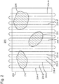
- a preliminary survey test 200 e.g., run only a few lines (e.g., lines 204-1, 204-6, 204-11, 204-17 and 204-N, where N can take various values depending on the size of the full survey) of the full survey (204-1 to 204-N).
- the number of lines of the preliminary survey test is illustrative only. Those skilled in the art would recognize that this number depends on the specific features of the subsurface. For example, if, during the preliminary survey, data acquisition along line 204-11 indicates a likelihood of encountering an area 220 having different characteristics than area 202, the next survey lines may be denser so that the approximate shape of area 220 is identified.
- the preliminary survey uses a "scanning source" to help determine favorable angles for target illumination.
- the source array may be activated using any beam shape, and seismic data is recorded with the streamer spread. Then, the recorded seismic data may be processed onboard the vessel, or it may be sent to a land processing center for quick processing. Applying known processing algorithms, e.g., migration, mirror migration, full waveform inversion, etc., a basic final image of the area of interest may be determined. Based on this image or other parameters, it may be determined that there are one or more areas (210, 220, or 230) needing special attention during the full survey. As discussed above, these areas may include chalk, salt dome, dipping regions, faults, canyons, methane clathrates, gas zones, etc. that necessitate special attention.
- area 210 is identified to be a chalk region
- area 220 is identified to be a salt dome
- area 230 is identified to include severe dipping regions.
- the controller may dynamically select the beam form factors for each source element of the source array during the seismic survey to optimally illuminate each area.
- the adaptable source array is adjusted during the full survey so that its beam is directed to illuminate the target zone at a favorable angle for that particular source point based upon the prior scanning source survey result. The favorable angle is likely to change with each source point.
- new form factors are applied only after a preset number of source points have been shot.
- FIG 3 illustrates a seismic vessel 301 towing a source array 303 comprised of vibro-acoustic elements 305 that have origin/centroid location 311, and which can be used to generate one or more acoustic beams of energy as discussed below.
- the vessel 301 also tows a streamer array 309 having multiple receivers 307 to receive the reflected acoustic waves.
- the vibro-acoustic elements 305 can be located all at a common depth or towed at different depths, an example of the latter configuration being provided below with respect to Figure 4 .
- beam steering may be achieved in various ways.
- each source array source element may be individually controlled, the entire source array may be controlled in a way that produces a "phased" or "beam steered” array.
- source elements are all operated synchronously (in phase with one another), and the source array's dimension is small to avoid directivity notches in particular directions for frequencies of interest, with the objective of the source array uniformly illuminating the target area.
- it is advantageous to steer source array emissions.
- One way to change the source array's directivity pattern is to operate multiple source elements at the same phase, but have them operate at different depths. This creates a tilted acoustic wave front; its main lobe attains a maximum at an angle away from vertical.
- the source array has a fixed geometry and it can be difficult to modify the source elements' positions in a short time.
- the vessel 301 is constantly moving, typically traveling in a straight line for a few miles, and then turning around to collect data along a path parallel to the previous pass, but in the opposite direction.
- means to change the source acoustic energy directivity pattern that takes into account subterranean geometry, vessel location, and streamer spread location so as to maintain favorable target illumination are valuable.
- source elements operating at approximately the same depth can be phased differently.
- the result is that the source array's directivity pattern can be tilted to approximate the same pattern as source elements operating synchronously at different depths.
- Phasing can be just a time delay, but because of the surface ghost contribution, in practice, the phasing scheme may be more complicated.
- source element amplitude Another factor that can change source array directivity patterns is source element amplitude. While it is ordinarily desirable to operate all source elements at their maximum output, it is anticipated that in some situations it might be desirable to have the output of at least one source element different from the others.
- the difference in amplitude could be invariant with frequency or change with frequency.
- a special case might be to use variable amplitudes to tune out the direct arrival (horizontally propagating) energy from the source array that impinges on the near offset hydrophones (see, for example, Sallas, US 4,918,668 , the entire content of which is incorporated herein by reference).
- this constraint could be incorporated into a cost function as part of the target directivity pattern.
- the beam-steering process can also be used to create ghost notch diversity when the source elements are disposed at different depths. If the source elements are disposed at the same depth, the ghost notch diversity may be achieved for energy propagating away from the vertical angle. For example, in marine acquisition, spectral notches in down-going acoustic energy can occur in the amplitude spectrum of conventional constant depth source arrays due to the effect of destructive interference with the surface reflection. Dual-depth or variable-depth source elements provide means to counter this effect. One option is a curved source array.
- the source elements are located at different depths, reflections will constructively and destructively interfere, causing spectral notches to be filled in when compared to constant depth arrays.
- Another option might be to use one or more of the source elements at different depths. In other words, it is possible to operate, for a low-frequency sweep (e.g., 5-25 Hz) some source elements at a 25 m depth, and for a high-frequency sweep (e.g., 25-125 Hz), to operate some of the source elements at a 5 m depth.
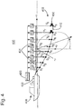
- a source array 400 includes at least one source sub-array 402 having plural source elements S 1 to S 8 suspended from a support device 404 (e.g., a float) attached to a vessel 406.
- Source elements S 1 to S 8 are distributed along a curved line 410, which may be a parameterized curve.
- a pilot signal 420 that can be a conventional swept sine over a predetermined frequency range or some other excitation signal, for example, a band-limited pseudorandom signal, can be convolved with beam form filters G 1 to G 8 (to be calculated by a process disclosed next) to form drive signals V 1 to V 8 .
- multiple pilot signals may be used to generate plural beams.
- the pilot signal(s) and the beam form factors may be processed in a controller 422 on vessel 406 or in a distributed controller that has some parts on the actual source elements. These signals may be stored in the memory of the source controllers 430, which are located at the source elements, on controller 422, or distributed between the source elements and the vessel's controller.
- sources S 1 to S 8 Upon receiving a command from the controller 422, sources S 1 to S 8 emit an acoustic signal using a feedback control system to emit acoustic energy that tracks drive signals V 1 to V 8 .
- acoustic emissions of source elements S 1 to S 8 have the same amplitude and phase spectra as drive signals V 1 to V 8 that are used as reference signals by the respective source elements S 1 to S 8 source controllers.
- Beam form filters G 1 to G 8 are designed to adjust the pilot signal phase and/or amplitude to ensure that acoustic energy radiated by the source array is maximized in a preferred direction over a frequency band of interest.
- this preferential angle is the vertical angle ⁇ over a range of azimuths.
- the azimuth angle ⁇ is useful for describing the beam width.
- Beam form filters G 1 to G 8 may be designed, as a function of the source array's geometry, to direct the radiated acoustic energy with a desired vertical angle and/or azimuth angle for illuminating selected features of the subsurface of interest.
- multiple pilot signals can be used to drive the source array elements in a manner which generates multiple beams or lobes of acoustic energy with desired vertical and azimuthal angles as shown conceptually in Figure 5 .
- three beams 501, 503 and 505 of acoustic energy are generated for illuminating subterranean targets in different ways.
- the beams 501, 503, 505 can be directed to have different preferred directions (as shown in Figure 5 ) or can alternatively some or all can be directed in a common direction but each with a different beam width so that the source illumination aperture can be changed.
- the beams can each have different effective source origins (centroids) to create a different source offset for each beam.
- the preferred directions can be directed at different azimuths and or different vertical angles or both, as in Figure 5 , wherein all three beams 501, 503 and 505 share a common origin.
- the vibro-acoustic source array elements 305 are sufficiently linear in their response it is possible to superimpose/combine a plurality of coded excitation signals (also referred to herein as pilot or code signals) to form a composite drive signal that can be used to excite a vibro-acoustic device without creating intermodulation distortion noise products.
- the three beam embodiment of Figure 5 can be generated as shown in Figures 6(a) and 6(b) .
- three differently coded pilot signals (Code 1, Code 2 and Code 3) can be convolved with three banks of directivity filters (as shown in Figure 6(a) ) that can be combined and used to create a suite of drive signals (U 1 , ...
- the source array 303 need not be limited to an array towed behind a single vessel 301 as depicted in Figure 3 , but these plural beam steering, seismic acquisition techniques could also be applied to the source elements within a super-array, an example of which is depicted in Figure 7 .
- three towing vessels 701, 707 and 711 tow three source arrays 703, 709 and 713, respectively.
- Vessel 701 also tows a streamer array 705.
- By using different source elements in different ones of the arrays 703, 709 and 713 to comprise at least a portion of each coded beam it is possible to spatially shift or offset the various beams from one another as is indicated by the three beam origins in Figure 7 shown as 715, 717 and 719.
- this spatial shift could be realized by using different amplitude levels and/or an amplitude weighting when combining the various beam signals to form the drive signals (U 1 ... U N ).
- some of the filter elements within a particular filter bank can be set to zero so that a particular source is not used to emit a particular code.
- FIG 8 illustrates some of the multiple beam steering possibilities that might arise according to various embodiments using a Venn diagram.
- Venn circle A1 is the set of vibro-acoustic elements required to form beam 501
- Venn circle A2 is the set of vibro-acoustic elements required to form beam 503
- Venn circle A3 represents all of the vibro-acoustic elements needed to form beam 505.
- these vibro-acoustic sources may have composite drive signals that contain two or more coded signals so that there is simultaneous emission of more than one coded source signal occurring in these elements.
- those source elements may have drive signals that have a contribution from only one pilot signal.
- code 1, code 2 and code 3 illustrated in Figure 8 can be implemented as three different pseudorandom sequences, e.g., orthogonal or pseudo-orthogonal sweeps, which are uncorrelated with each other over a time interval of interest.
- pseudorandom sequences e.g., orthogonal or pseudo-orthogonal sweeps
- One way to construct pseudorandom signals that are uncorrelated over some time interval of interest (+/- listen time) is taught in US Patent 7,859,945 .
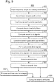
- Figure 9 generally illustrates a process to create the composite drive signals, acquire the survey data and finally deblend or separate the data sets according to an embodiment.
- the process begins with the input of the frequency range(s) to be used in the transmitted acoustic energy and other survey parameters as will be known to those skilled in the art. Then, the number and shapes of the plural beams are selected in step 904.
- the number of different beams that can be formed will be limited by the number and location of the various source elements-control/design of more than three beams operating simultaneously may be a challenge, although the present invention is not limited to three or fewer beams.
- the preferred direction of the beams will in part be determined by several factors: the relative position of the source elements with respect to the selected target to be imaged and the streamer(s) position, the vessel direction and the dip angle of the target reflector.
- a first vessel may be towing both a source array and a set of streamers, while a second source vessel operates at some crossline offset.
- a first beam may be directed toward the back of the vessel towing the streamer while a second beam may simultaneously be directed toward the target in a direction about normal to the reflection plane, while a third beam could be more omnidirectional or the third beam could be directed toward a second target of interest.
- Another option for example, where there is little prior knowledge of the survey area, would be to direct the beams deliberately in two or three different directions, primarily downward but tilted at different azimuth angles (for example 30 degrees apart), in processing after the records have been deblended, the separated records could be recombined to form a new record where the angle of illumination can be changed.
- the source configuration geometry is loaded at step 906, e.g., the X, Y, and Z position of each source element in one or more source arrays used to generate the acoustic waves.
- the beam directivity filters G and the coded pilot signals are computed in steps 908 and 910, respectively. These computations can, for example, be performed as described (for multiple beam directivity filters and individual pilot signals) in the above-incorporated by reference '317 application. However, to assist the reader in understanding these steps, an example is provided below with respect to Figure 10 .
- the coded pilot signals are convolved with the beam filters at step 912 and then combined or superimposed together to form the composite drive signals at step 914, for example as described above with respect to Figures 6(a) and 6(b) .
- the drive signals can then be downloaded into one or more source controllers at step 916, which operate the individual continuous vibratory source elements using the drive signals.
- the seismic data is then acquired at step 918, e.g., by receiver elements such as hydrophones, geophones or the like, which data is recorded for further processing either onboard the acquisition vessel(s) or onshore.
- the coded pilot sequences computed at step 910 are sufficiently orthogonal, they can be deblended at step 920 by cross-correlation with the different coded pilot signals.
- the correlation process will also compress the data set to resemble data that might be acquired using impulsive sources.
- the correlated data sets are input to other processing sequences (not specifically shown in Figure 9 , but generally represented by step 922) to produce an image.
- Other processing methods such as source signature deconvolution or a least squares inversion process could also be used to deblend the data set and form multiple images.
- the resulting images could be differenced, combined to increase spatial resolution or analyzed in other steps not shown to compute gradients, seismic attributes or features that are useful for detection of hydrocarbons or useful for further characterization of the subterranean geology as generally represented by step 924.
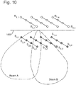
- FIG 10 illustrates how steps 908-914 of the above-described seismic acquisition method could be implemented for a purely illustrative source/receiver geometry.
- 16 source elements are towed at the same depth below the water's surface 1000 behind a vessel (not shown in Figure 10 ), i.e., using four towed lines each with four source elements each.
- the signals emitted by each source element are labeled as S 1,1 , S 1,2 ...S 4,4 where the first subscript is the tow line index and the second subscript represents the element position number in a particular towed line.
- this particular seismic acquisition design is intended to direct the seismic emissions from the array in two different directions simultaneously, and call the first directed energy Beam A and the second directed energy Beam B.
- the contribution of the surface ghost labeled R 1,1 , R 1,2 ...R 4,4 may or may not be included, but are not mentioned below for simplicity.
- One reason for not including the water surface reflection in the directivity pattern/phase shift calculations is that in many cases the "ghost" is removed during processing of the acquired seismic data. If this is the case it may be preferable to calculate the beam form filter operators based on only the primary signals, that is to assume the sources operate in a free-field with no surface ghost effect; because after deghosting the effective source array directivity will behave as if the sources were operated in a free-field.
- Pilot A and Pilot B two pseudorandom signals are used to generate the drive signals, referred to here as Pilot A and Pilot B, where A and B are designed to be pseudo-orthogonal signals or uncorrelated signals as mentioned above.
- Pilot A and Pilot B two pseudorandom signals are used to generate the drive signals, referred to here as Pilot A and Pilot B, where A and B are designed to be pseudo-orthogonal signals or uncorrelated signals as mentioned above.
- an array 2Aof phase shift filter operators ⁇ 2A 1,1 (f)... 2A 4,4 (f) ⁇ have been computed for each frequency f of Pilot A signal so that when the resultant drive signals are emitted by the corresponding source elements they combine to create an emission directivity pattern corresponding to Beam A.
- Coded directivity drive signals S 1,1 , S 1,2 ...S 4,4 are then formed by combining the drive signals a 1,1 (k),...a 4,4 (k), and b 1,1 (k),...b 4,4 (k).
- the amplitude of the signals may be adjusted to ensure that equipment constraints are not exceeded.
- FIG. 11 Another method 1100 for seismic data acquisition according to an embodiment is illustrated in Figure 11 .
- the number of beams of acoustic energy to be formed e.g., two or more
- a different pilot signal is then generated for each of the number of beams of acoustic energy at step 1104, which in turn are used to generate the plurality of drive signals at step 1106, e.g., as described above.
- the drive signals are then used to drive an array of source elements to generate the two or more beams of acoustic energy at step 1108.
- embodiments can also be expressed as systems which are capable of performing such methods.
- An example of a representative control system capable of carrying out operations in accordance with the exemplary embodiments discussed above is illustrated in Figure 12 .
- Hardware, firmware, software or a combination thereof may be used to perform the various steps and operations described herein.
- the exemplary control system 1200 suitable for performing the activities described in the above-noted embodiments may include server 1201.
- server 1201 may include a central processor unit (CPU) 1202 coupled to a random access memory (RAM) 1204 and to a read-only memory (ROM) 1206.
- ROM 1206 may also be other types of storage media to store programs, such as programmable ROM (PROM), erasable PROM (EPROM), etc.
- Processor 1202 may communicate with other internal and external components through input/output (I/O) circuitry 1208 and bussing 1210, to provide control signals and the like.
- processor 1202 may communicate with the sensors, electro-magnetic actuator system and/or the pressure equalization mechanism of the source element.
- Processor 1202 carries out a variety of functions as are known in the art, as dictated by software and/or firmware instructions.
- Server 1201 may also include one or more data storage devices, including hard and disk drives 1212, CD-ROM drives 1214, and other hardware capable of reading and/or storing information, such as a DVD, etc.
- software for carrying out the above-discussed steps may be stored and distributed on a CD-ROM 1216, removable media 1218 or other form of media capable of portably storing information. These storage media may be inserted into, and read by, devices such as the CD-ROM drive 1214, the disk drive 1212, etc.
- Server 1201 may be coupled to a display 1220, which may be any type of known display or presentation screen, such as LCD, plasma displays, cathode ray tubes (CRT), etc.
- a user input interface 1222 is provided, including one or more user interface mechanisms such as a mouse, keyboard, microphone, touch pad, touch screen, voice-recognition system, etc.
- Server 1201 may be coupled to other computing devices, such as the equipment of a vessel, via a network.
- the server may be part of a larger network configuration as in a global area network (GAN) such as the Internet 1228, which allows ultimate connection to the various landline and/or mobile client/watcher devices.
- GAN global area network
- the exemplary embodiments may be embodied in a wireless communication device, a telecommunication network, as a method or in a computer program product. Accordingly, the exemplary embodiments may take the form of an entirely hardware embodiment or an embodiment combining hardware and software aspects. Further, the exemplary embodiments may take the form of a computer program product stored on a computer-readable storage medium having computer-readable instructions embodied in the medium. Any suitable computer-readable medium may be utilized, including hard disks, CD-ROMs, digital versatile discs (DVD), optical storage devices or magnetic storage devices such a floppy disk or magnetic tape. Other non-limiting examples of computer-readable media include flash-type memories or other known types of memories.
- the system may further include the source elements, receiver elements, source control elements and/or any of the hardware described above with respect to seismic acquisition systems.
Landscapes
- Life Sciences & Earth Sciences (AREA)
- Physics & Mathematics (AREA)
- Engineering & Computer Science (AREA)
- Remote Sensing (AREA)
- Geology (AREA)
- Environmental & Geological Engineering (AREA)
- Acoustics & Sound (AREA)
- General Life Sciences & Earth Sciences (AREA)
- General Physics & Mathematics (AREA)
- Geophysics (AREA)
- Oceanography (AREA)
- Geophysics And Detection Of Objects (AREA)
- Measurement Of Velocity Or Position Using Acoustic Or Ultrasonic Waves (AREA)
Claims (12)
- Verfahren zur Erfassung seismischer Daten, wobei das Verfahren Folgendes umfasst:Bestimmen (1102) einer Anzahl von Strahlen akustischer Energie, die für die Erfassung seismischer Daten zu erzeugen sind, wobei die Anzahl größer als eins ist,Erzeugen (1104) eines anderen Pilotsignals für jeden der Anzahl der Strahlen akustischer Energie,Erzeugen (1106) mehrerer Ansteuersignale unter Verwendung der verschiedenen Pilotsignale undAnsteuern (1108) eines Feldes von Quellelementen unter Verwendung der mehreren Ansteuersignale, um die zwei oder mehr Strahlen akustischer Energie zu erzeugen,dadurch gekennzeichnet, dass der Schritt des Erzeugens mehrerer Ansteuersignale ferner Folgendes umfasst:Falten jedes der mehreren verschiedenen Pilotsignale mit Strahlfiltern, um vorläufige Ansteuersignale zu erzeugen, undAddieren oder Überlagern von mindestens zwei der vorläufigen Ansteuersignale miteinander, um eines der mehreren Ansteuersignale zu erzeugen.
- Verfahren nach Anspruch 1, wobei der Schritt des Bestimmens der Anzahl an Strahlen ferner Folgendes umfasst:
Auswählen von entweder zwei oder drei als die Anzahl an Strahlen akustischer Energie, die zu erzeugen sind. - Verfahren nach Anspruch 1, wobei der Schritt des Erzeugens verschiedener Pilotsignale ferner Folgendes umfasst:
Auswählen von zwei oder drei pseudozufälligen Signalen, die über ein Zeitintervall von Interesse nicht miteinander korrelieren. - Verfahren nach Anspruch 1, wobei jeder der mehreren Strahlen eine Richtcharakteristik aufweist, die durch einen vertikalen Winkel zwischen dem Strahl und der Schwerkraft und durch einen Azimutwinkel des Strahls beschrieben ist.
- Verfahren nach Anspruch 4, wobei jeder der mehreren Strahlen den gleichen vertikalen Winkel, aber einen anderen Azimutwinkel aufweist.
- Verfahren nach Anspruch 4, wobei jeder der mehreren Strahlen einen anderen vertikalen Winkel, aber den gleichen Azimutwinkel aufweist.
- Verfahren nach Anspruch 4, wobei jeder der Strahlen den gleichen Ausgangspunkt aufweist.
- Verfahren nach Anspruch 4, wobei mindestens einer der Strahlen einen anderen Ausgangspunkt als die anderen Strahlen aufweist.
- Verfahren nach Anspruch 1, wobei mindestens eines der Ansteuersignale einen Beitrag von nur einem der Pilotsignale aufweist.
- Verfahren nach Anspruch 1, ferner Folgendes umfassend:Empfangen von Reflexionen der Strahlen akustischer Energie an mehreren Empfängern, um empfangene Signale zu erzeugen, undEntmischen der empfangenen Signale, um Beträge von den zwei oder mehr Strahlen zu separieren.
- System zur seismischen Erfassung, Folgendes umfassend:einen Prozessor (1202), der dafür konfiguriert ist, für jeden von mehreren Strahlen akustischer Energie ein anderes Pilotsignal zu erzeugen,mehrere Strahlformfilter (G1,1...G3,N), die dafür konfiguriert sind, unter Verwendung der verschiedenen Pilotsignale mehrere Ansteuersignale zu erzeugen, undmindestens ein Feld von Quellelementen (309, 705, 709, 713), die dafür konfiguriert sind, durch die mehreren Ansteuersignale angesteuert zu werden, um die mehreren Strahlen akustischer Energie zu erzeugen,dadurch gekennzeichnet, dass die mehreren Strahlformfilter (G1,1...G3,N) dafür konfiguriert sind, jedes der mehreren verschiedenen Pilotsignale zu falten, um vorläufige Ansteuersignale zu erzeugen,und dadurch, dass das System ferner mehrere kombinierende Elemente umfasst, die dafür konfiguriert sind, eines der mehreren Ansteuersignale durch Addieren oder Überlagern von mindestens zwei der vorläufigen Ansteuersignale miteinander zu erzeugen.
- System nach Anspruch 11, wobei der Prozessor dafür konfiguriert ist, die verschiedenen Pilotsignale durch Auswählen von zwei oder drei pseudozufälligen Signalen zu erzeugen, die über ein Zeitintervall von Interesse nicht miteinander korrelieren.
Applications Claiming Priority (2)
| Application Number | Priority Date | Filing Date | Title |
|---|---|---|---|
| US201361876811P | 2013-09-12 | 2013-09-12 | |
| PCT/EP2014/069366 WO2015036468A2 (en) | 2013-09-12 | 2014-09-11 | Methods and systems for seismic imaging using coded directivity |
Publications (2)
| Publication Number | Publication Date |
|---|---|
| EP3044609A2 EP3044609A2 (de) | 2016-07-20 |
| EP3044609B1 true EP3044609B1 (de) | 2018-09-05 |
Family
ID=51535436
Family Applications (1)
| Application Number | Title | Priority Date | Filing Date |
|---|---|---|---|
| EP14762004.1A Not-in-force EP3044609B1 (de) | 2013-09-12 | 2014-09-11 | Verfahren und systeme zur seismischen bildgebung mittels codierter richtcharakteristik |
Country Status (5)
| Country | Link |
|---|---|
| US (1) | US9874650B2 (de) |
| EP (1) | EP3044609B1 (de) |
| DK (1) | DK3044609T3 (de) |
| MX (1) | MX2016003192A (de) |
| WO (1) | WO2015036468A2 (de) |
Families Citing this family (6)
| Publication number | Priority date | Publication date | Assignee | Title |
|---|---|---|---|---|
| EP3137926A4 (de) | 2014-04-28 | 2017-12-13 | Westerngeco LLC | Rekonstruktion eines wellenfeldes |
| MX381934B (es) | 2015-05-01 | 2025-03-13 | Reflection Marine Norge As | Prospección con fuentes directivas de vibradores marinos. |
| WO2016179206A1 (en) | 2015-05-05 | 2016-11-10 | Schlumberger Technology Corporation | Removal of acquisition effects from marine seismic data |
| MX392202B (es) | 2015-12-02 | 2025-03-21 | Schlumberger Technology Bv | Tendido de sensores sismicos terrestres con pares de sensores sismicos de multiples componentes adyacentes en promedio a una distancia de al menos veinte metros. |
| GB2566240A (en) | 2016-06-15 | 2019-03-06 | Schlumberger Technology Bv | Systems and methods for acquiring seismic data with gradient data |
| EP4185897B1 (de) * | 2020-07-23 | 2025-09-03 | BP Corporation North America Inc. | Verfahren zur durchführung einer seismischen untersuchung mit beabstandeten quellenaktivierungslinien |
Family Cites Families (14)
| Publication number | Priority date | Publication date | Assignee | Title |
|---|---|---|---|---|
| US3346068A (en) | 1966-10-20 | 1967-10-10 | Atlantic Richfield Co | Focusing and scanning either or both of a plurality of seismic sources and seismometers to produce an improved seismic record |
| NO146924C (no) * | 1976-07-28 | 1982-12-29 | Mobil Oil Corp | Fremgangsmaate ved marine seismiske undersoekelser |
| US4146870A (en) | 1976-07-28 | 1979-03-27 | Mobil Oil Corporation | Seismic exploration for dipping formations |
| US4357689A (en) | 1976-07-28 | 1982-11-02 | Mobil Oil Corporation | Seismic data gathering method |
| US4918668A (en) | 1989-01-30 | 1990-04-17 | Halliburton Geophysical Services, Inc. | Marine vibrator tuneable array |
| US5281773A (en) | 1991-08-28 | 1994-01-25 | Exxon Production Research Company | Controlled phase marine source subarray |
| US6181646B1 (en) * | 1997-01-07 | 2001-01-30 | Hyroacoustics, Inc. | Geophysical exploration system using seismic vibrator source which provides a composite sweep |
| US7859945B2 (en) | 2007-07-06 | 2010-12-28 | Cggveritas Services Inc. | Efficient seismic data acquisition with source separation |
| US8867307B2 (en) | 2007-11-14 | 2014-10-21 | Acoustic Zoom, Inc. | Method for acoustic imaging of the earth's subsurface using a fixed position sensor array and beam steering |
| US8077547B2 (en) * | 2008-09-26 | 2011-12-13 | Providence technologies, Inc. | Method and apparatus for seismic exploration |
| KR101753065B1 (ko) * | 2010-09-02 | 2017-07-03 | 삼성전자주식회사 | 공간 음향 에너지 분포 조절 방법 및 장치 |
| US9110179B2 (en) * | 2010-11-12 | 2015-08-18 | Chevron U.S.A. Inc. | Integrated system for investigating sub-surface features of a rock formation |
| FR2981746B1 (fr) | 2011-10-19 | 2014-11-21 | Cggveritas Services Sa | Source et procede d'acquisition sismique marine |
| EP3008492A2 (de) | 2013-06-13 | 2016-04-20 | CGG Services SA | Anpassbare seismische quelle für seismische messungen und verfahren |
-
2014
- 2014-09-11 US US14/911,564 patent/US9874650B2/en not_active Expired - Fee Related
- 2014-09-11 EP EP14762004.1A patent/EP3044609B1/de not_active Not-in-force
- 2014-09-11 MX MX2016003192A patent/MX2016003192A/es unknown
- 2014-09-11 DK DK14762004.1T patent/DK3044609T3/en active
- 2014-09-11 WO PCT/EP2014/069366 patent/WO2015036468A2/en not_active Ceased
Also Published As
| Publication number | Publication date |
|---|---|
| US9874650B2 (en) | 2018-01-23 |
| US20160202379A1 (en) | 2016-07-14 |
| WO2015036468A3 (en) | 2015-06-04 |
| EP3044609A2 (de) | 2016-07-20 |
| MX2016003192A (es) | 2016-06-24 |
| WO2015036468A2 (en) | 2015-03-19 |
| DK3044609T3 (en) | 2019-01-07 |
Similar Documents
| Publication | Publication Date | Title |
|---|---|---|
| US10802167B2 (en) | Seismic acquisition method and apparatus | |
| US20230408719A1 (en) | Marine vibrator directive source survey | |
| EP3044609B1 (de) | Verfahren und systeme zur seismischen bildgebung mittels codierter richtcharakteristik | |
| US10520640B2 (en) | Method and system for adjusting seismic source pilot and drive signals using measured data | |
| US20200174147A1 (en) | Method for seismic data acquisition and processing | |
| US20160131785A1 (en) | Method and system for marine seismic acquisition | |
| WO2014114682A1 (en) | Apparatus and method for determination of far-field signature for marine seismic vibrator source | |
| US9625596B2 (en) | Vibrator source array beam-forming and method | |
| US20170276774A1 (en) | Method and device for boosting low-frequencies for a marine seismic survey | |
| US20150226867A1 (en) | Beam steered broadband marine survey method and system | |
| US9921328B2 (en) | Adaptable seismic source for seismic surveys and method | |
| US20190120987A1 (en) | Positioning seismic sources in a tuned source array | |
| WO2015145260A2 (en) | Method and apparatus for directional designature | |
| US9482765B2 (en) | Vibrator source array load-balancing method and system | |
| GB2567965A (en) | Positioning seismic sources in a tuned source array | |
| GB2567966A (en) | Tuned seismic source arrays |
Legal Events
| Date | Code | Title | Description |
|---|---|---|---|
| PUAI | Public reference made under article 153(3) epc to a published international application that has entered the european phase |
Free format text: ORIGINAL CODE: 0009012 |
|
| 17P | Request for examination filed |
Effective date: 20160204 |
|
| AK | Designated contracting states |
Kind code of ref document: A2 Designated state(s): AL AT BE BG CH CY CZ DE DK EE ES FI FR GB GR HR HU IE IS IT LI LT LU LV MC MK MT NL NO PL PT RO RS SE SI SK SM TR |
|
| AX | Request for extension of the european patent |
Extension state: BA ME |
|
| DAX | Request for extension of the european patent (deleted) | ||
| 17Q | First examination report despatched |
Effective date: 20171204 |
|
| GRAP | Despatch of communication of intention to grant a patent |
Free format text: ORIGINAL CODE: EPIDOSNIGR1 |
|
| INTG | Intention to grant announced |
Effective date: 20180522 |
|
| GRAS | Grant fee paid |
Free format text: ORIGINAL CODE: EPIDOSNIGR3 |
|
| GRAA | (expected) grant |
Free format text: ORIGINAL CODE: 0009210 |
|
| RAP1 | Party data changed (applicant data changed or rights of an application transferred) |
Owner name: CGG SERVICES SAS |
|
| AK | Designated contracting states |
Kind code of ref document: B1 Designated state(s): AL AT BE BG CH CY CZ DE DK EE ES FI FR GB GR HR HU IE IS IT LI LT LU LV MC MK MT NL NO PL PT RO RS SE SI SK SM TR |
|
| REG | Reference to a national code |
Ref country code: GB Ref legal event code: FG4D |
|
| REG | Reference to a national code |
Ref country code: CH Ref legal event code: EP |
|
| REG | Reference to a national code |
Ref country code: AT Ref legal event code: REF Ref document number: 1038479 Country of ref document: AT Kind code of ref document: T Effective date: 20180915 |
|
| REG | Reference to a national code |
Ref country code: FR Ref legal event code: PLFP Year of fee payment: 5 |
|
| REG | Reference to a national code |
Ref country code: IE Ref legal event code: FG4D |
|
| REG | Reference to a national code |
Ref country code: DE Ref legal event code: R096 Ref document number: 602014031828 Country of ref document: DE |
|
| PGFP | Annual fee paid to national office [announced via postgrant information from national office to epo] |
Ref country code: DK Payment date: 20180928 Year of fee payment: 5 |
|
| REG | Reference to a national code |
Ref country code: NL Ref legal event code: FP |
|
| PGFP | Annual fee paid to national office [announced via postgrant information from national office to epo] |
Ref country code: NL Payment date: 20180928 Year of fee payment: 5 |
|
| REG | Reference to a national code |
Ref country code: DK Ref legal event code: T3 Effective date: 20190103 |
|
| REG | Reference to a national code |
Ref country code: LT Ref legal event code: MG4D |
|
| PG25 | Lapsed in a contracting state [announced via postgrant information from national office to epo] |
Ref country code: BG Free format text: LAPSE BECAUSE OF FAILURE TO SUBMIT A TRANSLATION OF THE DESCRIPTION OR TO PAY THE FEE WITHIN THE PRESCRIBED TIME-LIMIT Effective date: 20181205 Ref country code: RS Free format text: LAPSE BECAUSE OF FAILURE TO SUBMIT A TRANSLATION OF THE DESCRIPTION OR TO PAY THE FEE WITHIN THE PRESCRIBED TIME-LIMIT Effective date: 20180905 Ref country code: GR Free format text: LAPSE BECAUSE OF FAILURE TO SUBMIT A TRANSLATION OF THE DESCRIPTION OR TO PAY THE FEE WITHIN THE PRESCRIBED TIME-LIMIT Effective date: 20181206 Ref country code: LT Free format text: LAPSE BECAUSE OF FAILURE TO SUBMIT A TRANSLATION OF THE DESCRIPTION OR TO PAY THE FEE WITHIN THE PRESCRIBED TIME-LIMIT Effective date: 20180905 Ref country code: FI Free format text: LAPSE BECAUSE OF FAILURE TO SUBMIT A TRANSLATION OF THE DESCRIPTION OR TO PAY THE FEE WITHIN THE PRESCRIBED TIME-LIMIT Effective date: 20180905 Ref country code: SE Free format text: LAPSE BECAUSE OF FAILURE TO SUBMIT A TRANSLATION OF THE DESCRIPTION OR TO PAY THE FEE WITHIN THE PRESCRIBED TIME-LIMIT Effective date: 20180905 |
|
| REG | Reference to a national code |
Ref country code: NO Ref legal event code: T2 Effective date: 20180905 |
|
| REG | Reference to a national code |
Ref country code: AT Ref legal event code: MK05 Ref document number: 1038479 Country of ref document: AT Kind code of ref document: T Effective date: 20180905 |
|
| PG25 | Lapsed in a contracting state [announced via postgrant information from national office to epo] |
Ref country code: AL Free format text: LAPSE BECAUSE OF FAILURE TO SUBMIT A TRANSLATION OF THE DESCRIPTION OR TO PAY THE FEE WITHIN THE PRESCRIBED TIME-LIMIT Effective date: 20180905 Ref country code: HR Free format text: LAPSE BECAUSE OF FAILURE TO SUBMIT A TRANSLATION OF THE DESCRIPTION OR TO PAY THE FEE WITHIN THE PRESCRIBED TIME-LIMIT Effective date: 20180905 Ref country code: LV Free format text: LAPSE BECAUSE OF FAILURE TO SUBMIT A TRANSLATION OF THE DESCRIPTION OR TO PAY THE FEE WITHIN THE PRESCRIBED TIME-LIMIT Effective date: 20180905 |
|
| REG | Reference to a national code |
Ref country code: DE Ref legal event code: R119 Ref document number: 602014031828 Country of ref document: DE |
|
| PG25 | Lapsed in a contracting state [announced via postgrant information from national office to epo] |
Ref country code: AT Free format text: LAPSE BECAUSE OF FAILURE TO SUBMIT A TRANSLATION OF THE DESCRIPTION OR TO PAY THE FEE WITHIN THE PRESCRIBED TIME-LIMIT Effective date: 20180905 Ref country code: IS Free format text: LAPSE BECAUSE OF FAILURE TO SUBMIT A TRANSLATION OF THE DESCRIPTION OR TO PAY THE FEE WITHIN THE PRESCRIBED TIME-LIMIT Effective date: 20190105 Ref country code: ES Free format text: LAPSE BECAUSE OF FAILURE TO SUBMIT A TRANSLATION OF THE DESCRIPTION OR TO PAY THE FEE WITHIN THE PRESCRIBED TIME-LIMIT Effective date: 20180905 Ref country code: PL Free format text: LAPSE BECAUSE OF FAILURE TO SUBMIT A TRANSLATION OF THE DESCRIPTION OR TO PAY THE FEE WITHIN THE PRESCRIBED TIME-LIMIT Effective date: 20180905 Ref country code: IT Free format text: LAPSE BECAUSE OF FAILURE TO SUBMIT A TRANSLATION OF THE DESCRIPTION OR TO PAY THE FEE WITHIN THE PRESCRIBED TIME-LIMIT Effective date: 20180905 Ref country code: RO Free format text: LAPSE BECAUSE OF FAILURE TO SUBMIT A TRANSLATION OF THE DESCRIPTION OR TO PAY THE FEE WITHIN THE PRESCRIBED TIME-LIMIT Effective date: 20180905 Ref country code: CZ Free format text: LAPSE BECAUSE OF FAILURE TO SUBMIT A TRANSLATION OF THE DESCRIPTION OR TO PAY THE FEE WITHIN THE PRESCRIBED TIME-LIMIT Effective date: 20180905 Ref country code: EE Free format text: LAPSE BECAUSE OF FAILURE TO SUBMIT A TRANSLATION OF THE DESCRIPTION OR TO PAY THE FEE WITHIN THE PRESCRIBED TIME-LIMIT Effective date: 20180905 |
|
| REG | Reference to a national code |
Ref country code: CH Ref legal event code: PL |
|
| PG25 | Lapsed in a contracting state [announced via postgrant information from national office to epo] |
Ref country code: SM Free format text: LAPSE BECAUSE OF FAILURE TO SUBMIT A TRANSLATION OF THE DESCRIPTION OR TO PAY THE FEE WITHIN THE PRESCRIBED TIME-LIMIT Effective date: 20180905 Ref country code: PT Free format text: LAPSE BECAUSE OF FAILURE TO SUBMIT A TRANSLATION OF THE DESCRIPTION OR TO PAY THE FEE WITHIN THE PRESCRIBED TIME-LIMIT Effective date: 20190105 Ref country code: SK Free format text: LAPSE BECAUSE OF FAILURE TO SUBMIT A TRANSLATION OF THE DESCRIPTION OR TO PAY THE FEE WITHIN THE PRESCRIBED TIME-LIMIT Effective date: 20180905 |
|
| REG | Reference to a national code |
Ref country code: BE Ref legal event code: MM Effective date: 20180930 |
|
| REG | Reference to a national code |
Ref country code: IE Ref legal event code: MM4A |
|
| PG25 | Lapsed in a contracting state [announced via postgrant information from national office to epo] |
Ref country code: LU Free format text: LAPSE BECAUSE OF NON-PAYMENT OF DUE FEES Effective date: 20180911 |
|
| PLBE | No opposition filed within time limit |
Free format text: ORIGINAL CODE: 0009261 |
|
| STAA | Information on the status of an ep patent application or granted ep patent |
Free format text: STATUS: NO OPPOSITION FILED WITHIN TIME LIMIT |
|
| PG25 | Lapsed in a contracting state [announced via postgrant information from national office to epo] |
Ref country code: DE Free format text: LAPSE BECAUSE OF NON-PAYMENT OF DUE FEES Effective date: 20190402 Ref country code: IE Free format text: LAPSE BECAUSE OF NON-PAYMENT OF DUE FEES Effective date: 20180911 Ref country code: MC Free format text: LAPSE BECAUSE OF FAILURE TO SUBMIT A TRANSLATION OF THE DESCRIPTION OR TO PAY THE FEE WITHIN THE PRESCRIBED TIME-LIMIT Effective date: 20180905 |
|
| 26N | No opposition filed |
Effective date: 20190606 |
|
| PG25 | Lapsed in a contracting state [announced via postgrant information from national office to epo] |
Ref country code: BE Free format text: LAPSE BECAUSE OF NON-PAYMENT OF DUE FEES Effective date: 20180930 Ref country code: SI Free format text: LAPSE BECAUSE OF FAILURE TO SUBMIT A TRANSLATION OF THE DESCRIPTION OR TO PAY THE FEE WITHIN THE PRESCRIBED TIME-LIMIT Effective date: 20180905 Ref country code: LI Free format text: LAPSE BECAUSE OF NON-PAYMENT OF DUE FEES Effective date: 20180930 Ref country code: CH Free format text: LAPSE BECAUSE OF NON-PAYMENT OF DUE FEES Effective date: 20180930 |
|
| PG25 | Lapsed in a contracting state [announced via postgrant information from national office to epo] |
Ref country code: MT Free format text: LAPSE BECAUSE OF NON-PAYMENT OF DUE FEES Effective date: 20180911 |
|
| PG25 | Lapsed in a contracting state [announced via postgrant information from national office to epo] |
Ref country code: TR Free format text: LAPSE BECAUSE OF FAILURE TO SUBMIT A TRANSLATION OF THE DESCRIPTION OR TO PAY THE FEE WITHIN THE PRESCRIBED TIME-LIMIT Effective date: 20180905 |
|
| REG | Reference to a national code |
Ref country code: DK Ref legal event code: EBP Effective date: 20190930 |
|
| REG | Reference to a national code |
Ref country code: NL Ref legal event code: MM Effective date: 20191001 |
|
| PG25 | Lapsed in a contracting state [announced via postgrant information from national office to epo] |
Ref country code: MK Free format text: LAPSE BECAUSE OF NON-PAYMENT OF DUE FEES Effective date: 20180905 Ref country code: HU Free format text: LAPSE BECAUSE OF FAILURE TO SUBMIT A TRANSLATION OF THE DESCRIPTION OR TO PAY THE FEE WITHIN THE PRESCRIBED TIME-LIMIT; INVALID AB INITIO Effective date: 20140911 Ref country code: CY Free format text: LAPSE BECAUSE OF FAILURE TO SUBMIT A TRANSLATION OF THE DESCRIPTION OR TO PAY THE FEE WITHIN THE PRESCRIBED TIME-LIMIT Effective date: 20180905 |
|
| PG25 | Lapsed in a contracting state [announced via postgrant information from national office to epo] |
Ref country code: NL Free format text: LAPSE BECAUSE OF NON-PAYMENT OF DUE FEES Effective date: 20191001 |
|
| PG25 | Lapsed in a contracting state [announced via postgrant information from national office to epo] |
Ref country code: DK Free format text: LAPSE BECAUSE OF NON-PAYMENT OF DUE FEES Effective date: 20190930 |
|
| PGFP | Annual fee paid to national office [announced via postgrant information from national office to epo] |
Ref country code: GB Payment date: 20200921 Year of fee payment: 7 Ref country code: FR Payment date: 20200914 Year of fee payment: 7 Ref country code: NO Payment date: 20200922 Year of fee payment: 7 |
|
| REG | Reference to a national code |
Ref country code: NO Ref legal event code: MMEP |
|
| GBPC | Gb: european patent ceased through non-payment of renewal fee |
Effective date: 20210911 |
|
| PG25 | Lapsed in a contracting state [announced via postgrant information from national office to epo] |
Ref country code: NO Free format text: LAPSE BECAUSE OF NON-PAYMENT OF DUE FEES Effective date: 20210930 Ref country code: GB Free format text: LAPSE BECAUSE OF NON-PAYMENT OF DUE FEES Effective date: 20210911 Ref country code: FR Free format text: LAPSE BECAUSE OF NON-PAYMENT OF DUE FEES Effective date: 20210930 |