EP3044404B1 - Vorrichtung zur impulserzeugung in einem bohrloch - Google Patents
Vorrichtung zur impulserzeugung in einem bohrloch Download PDFInfo
- Publication number
- EP3044404B1 EP3044404B1 EP14838889.5A EP14838889A EP3044404B1 EP 3044404 B1 EP3044404 B1 EP 3044404B1 EP 14838889 A EP14838889 A EP 14838889A EP 3044404 B1 EP3044404 B1 EP 3044404B1
- Authority
- EP
- European Patent Office
- Prior art keywords
- flow ports
- rotor
- pulse generator
- valve member
- rotary valve
- Prior art date
- Legal status (The legal status is an assumption and is not a legal conclusion. Google has not performed a legal analysis and makes no representation as to the accuracy of the status listed.)
- Active
Links
Images


Classifications
-
- E—FIXED CONSTRUCTIONS
- E21—EARTH OR ROCK DRILLING; MINING
- E21B—EARTH OR ROCK DRILLING; OBTAINING OIL, GAS, WATER, SOLUBLE OR MELTABLE MATERIALS OR A SLURRY OF MINERALS FROM WELLS
- E21B28/00—Vibration generating arrangements for boreholes or wells, e.g. for stimulating production
-
- E—FIXED CONSTRUCTIONS
- E21—EARTH OR ROCK DRILLING; MINING
- E21B—EARTH OR ROCK DRILLING; OBTAINING OIL, GAS, WATER, SOLUBLE OR MELTABLE MATERIALS OR A SLURRY OF MINERALS FROM WELLS
- E21B43/00—Methods or apparatus for obtaining oil, gas, water, soluble or meltable materials or a slurry of minerals from wells
- E21B43/003—Vibrating earth formations
-
- E—FIXED CONSTRUCTIONS
- E21—EARTH OR ROCK DRILLING; MINING
- E21B—EARTH OR ROCK DRILLING; OBTAINING OIL, GAS, WATER, SOLUBLE OR MELTABLE MATERIALS OR A SLURRY OF MINERALS FROM WELLS
- E21B7/00—Special methods or apparatus for drilling
- E21B7/24—Drilling using vibrating or oscillating means, e.g. out-of-balance masses
Definitions
- This disclosure relates generally to methods and apparatus for generating vibrations or fluid pulses with a downhole tool. More specifically, this disclosure relates to methods and apparatus that enable a downhole pulse generating device to generate pulses at a variety of frequencies and amplitudes.
- a prior art pulse generator is disclosed in e.g. US 8,181,719 B2 .
- Downhole pulse generating devices are used to create fluctuations in fluid pressure that create vibrations in the drill string.
- the vibrations or pulses can help prevent the build-up of solid materials around the drill string, which can reduce friction and prevent the drill string from becoming stuck in the well.
- the use of pulse generating devices can be useful in extending the operating range of drilling assemblies.
- a pulse generator comprises a stator coupled to a housing and a rotor that is rotatably disposed within the housing.
- An annulus is formed between the rotor and the stator.
- An inner bore is formed through the rotor.
- One or more outer flow ports provide fluid communication between the annulus and the inner bore.
- a retrievable valve assembly is rotationally coupled to the rotor and at least partially disposed within the inner bore.
- the retrievable valve assembly includes a rotary valve member having one or more primary flow ports.
- a fluid flow path is periodically formed by the one or more outer flow ports, the annulus, and the one or more primary flow ports as the rotor rotates.
- the retrievable valve assembly further comprises a linear adjustment mechanism for moving the rotary valve member linearly from a first position to a second position whilst the pulse generator is downhole.
- the rotary valve member is disposed within the inner bore and the primary flow ports are longitudinally aligned with the outer flow ports.
- the retrievable valve assembly further comprises a latching member coupled to the housing and a flexible shaft that couples the latching member to the rotary valve member.
- the primary flow ports are not longitudinally aligned with the outer flow ports.
- one or more secondary flow ports are disposed radially through the rotary valve member and when the rotary valve member is in the second position the secondary flow ports are longitudinally aligned with the outer flow ports.
- the pulse generator has a pass-through diameter that is limited by the inner bore of the rotor.
- a thrust bearing is coupled to the housing and in contact with the rotor, wherein the thrust bearing longitudinally constrains the rotor.
- the primary flow ports have a different shape or arrangement than the secondary flow ports.
- first and second features are formed in direct contact
- additional features may be formed interposing the first and second features, such that the first and second features may not be in direct contact.
- exemplary embodiments presented below may be combined in any combination of ways, i.e., any element from one exemplary embodiment may be used in any other exemplary embodiment, without departing from the scope of the disclosure as defined by the claims.
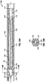
- a pulse generator 10 includes a housing 12, a progressive cavity motor 14, and a retrievable valve assembly 16.
- the progressive cavity motor 14 includes a stator 18 that is coupled to the inner diameter of the housing 12 and a rotor 20 that is disposed within, and rotatable relative to, the stator 18.
- the rotor 20 is longitudinally constrained by a thrust bearing 22 that is coupled to the housing 12. Thrust bearing 22 also limits the passage of fluid between the end of the rotor 20 and the thrust bearing 22, thus restricting the flow of fluid out of the annulus 40.
- the rotor 20 includes an inner bore 24 and one or more outer flow ports 26 that provide fluid communication across the wall of the rotor 20 between the annulus 40 and the inner bore 24.
- progressive cavity motor 14 may be replaced by an alternative rotating motor such as vaned hydraulic motor, an electric motor, or any other type of motor with a rotor that can interface with a retrievable valve assembly 16.
- the retrievable valve assembly 16 includes a latching member 28, a flexible shaft 30, and a rotary valve member 32.
- Retrievable valve assembly 16 is at least partially disposed within the inner bore 24 of the rotor 20.
- the latching member 28 couples the retrievable valve assembly 16 to the housing 12 via a connection 34.
- Connection 34 may be a shear pin, shear ring, mechanical latch system, or any other system that longitudinally and rotationally couples the retrievable valve assembly 16 to the housing 12. In certain embodiments, connection 34 may be releasable so that the retrievable valve assembly 16 can be removed from the pulse generator 10.
- Removal of the retrievable valve assembly 16 opens the inner bore 24 of rotor 20 so that the pulse generator 10 has a pass-through diameter that is limited by the inner bore 24.
- the open inner bore 24 allows other tools to be passed through the pulse generator 10 to support operations below the pulse generator 10.
- Latching member 28 may also include an overshot profile 35 or other feature that aids in the removal of the valve assembly 16 from the pulse generator 10.
- Rotary valve member 32 is disposed within the inner bore 24 of rotor 20 and is coupled to the latching member 28 by a flexible shaft 30.
- rotor 20, and therefore rotary valve member 32 will oscillate laterally relative to the stator 18 and housing 12.
- Flexible shaft 30 allows the rotary valve member 32 to oscillate with respect to the latching member 28 but substantially limits rotation of the rotary valve member 32 relative to the latching member 28.
- Flexible shaft 30 may be constructed from a unitary shaft or by a series of mechanical couplings.
- Rotary valve member 32 includes a solid upper end 37 that is coupled to the flexible shaft 30 and a valve body 39 that includes one or more primary flow ports 36.
- the valve body 39 may be a drum, having a solid upper end 37 and a hollow interior, or may be a substantially solid member with flow ports 36 formed therein.
- pressurized fluid is pumped into the pulse generator 10 through housing 12. Fluid passes through flow ports or openings 33 in latching member 28. Because the solid upper end 37 of the rotary valve member 32 restricts fluid from passing through the inner bore 24 of the rotor 20, the fluid passes through the annulus 40 between the stator 18 and the rotor 20. Fluid moving through annulus 40 causes the rotor 20 to rotate relative to the stator 18 and the rotary valve member 32. As the rotor 20 rotates, the outer flow ports 26 of the rotor 20 periodically align with, and become in fluid communication with, the primary flow ports 36 on the rotary valve member 32. When the outer flow ports 26 are aligned with the inner flow ports 36, fluid can flow from the annulus 40 into the interior of the rotary valve member 32. From the interior of the rotary valve member 32, the fluid moves through a bore 42 in the thrust bearing 22 and out of the pulse generator 10.
- the periodic alignment of the outer flow ports 26 and the inner flow ports 36 creates cyclical flow restrictions and flow paths as the flow of fluid is interrupted and allowed by intermittent alignment of the flow ports.
- a fluid flow path is periodically formed by the outer flow ports 26, the annulus 40, and the primary flow ports 36.
- This cyclical flow generates pressure pulses in the fluid moving through the pulse generator 10.
- the characteristics of the pressure pulse, including frequency, amplitude, dwell, and shape of the pressure pulses generated by the pulse generator 10 are dependent on the shape, size and position of both outer flow ports 26 and the primary flow ports 36, as well as the rotational speed of the rotor 20.
- outer flow ports 26 and/or primary flow ports 36 may be sized, shaped, and positioned in a variety of ways in order to create a desired pressure pulse when the pulse generator 10 is operated.
- Figures 2-7 are partial development views of flow ports that may be formed on either the rotary valve member 32 or the rotor 20. For purposes of the following explanation, each embodiment will be described as having primary flow ports disposed on the rotary valve member 32 with one or more equally spaced outer flow ports 26 disposed on the rotor 20, but is it understood that the location of these ports could be reversed.
- primary flow ports 36 include a plurality of uniform width slots 50 are substantially evenly spaced about the circumference of either the rotary valve member 32. As rotor 20 rotates and the primary flow ports 36 periodically align with outer flow ports 26 on the rotor 20. This periodic alignment between the primary flow ports 36 and the outer flow ports 26 creates an intermittent flow path between the annulus 40 into the interior of the rotary valve member 32.
- the slots 50 are equally sized and uniformly spaced the series of pressure pulses that are generated in the flow through the pulse generator 10 will have a repeating pattern of pulses at a generally equal magnitude. Increasing or decreasing the width of the slots 50 will similarly change the duration or amplitude of the pressure pulse being generated. Likewise, increasing or decreasing the distance between adjacent slots 50 will result in a pressure pulse frequency of the generated pulse. Thus, in other embodiments the spacing and size of the slots 50 may be varied so that the frequency and amplitude of the generated pulse can be selected for a desired application.
- primary flow ports 36 are shaped with a narrow leading edge 52 and are tapered to a wide trailing edge 54. As an inner flow port 36 passes over an outer flow port 26, the flow area through the aligned ports gradually increases as the width of the port increases from the leading edge 52 to the trailing edge 54. Once the inner flow port 36 passes the outer flow port 26, the generated pulse increases in amplitude as the width of the inner flow port 36 increases and then returns abruptly to zero once the trailing edge 54 passes over the outer flow port 26. The abrupt closing of the inner flow port 36 may cause a pressure spike in the flow of fluid and act as a fluid hammer on the pulse generator 10.
- primary flow ports 36 form a curve 56 that may have a substantially sinusoidal shape. As curve 56 passes over the outer flow ports 26, the amplitude and frequency of the pressure pulses formed will have a similar shape to the curve 56. Curve 56 may also be non-sinusoidal shape and in certain embodiments, may be non-uniform.
- certain embodiments of pulse generator 10 may have a rotary valve member 32 that can be moved longitudinally relative to the rotor 20.
- a longitudinally adjustable rotary valve member 32 may include primary flow ports 60 and secondary flow ports 62.
- the rotary valve member 32 In a first position, as shown in Figure 5 , the rotary valve member 32 is positioned so that flow through outer flow ports 26 is not restricted by the rotary valve member 32. In this first position, because the rotary valve member 32 does not restrict the flow through the outer flow ports 26, the pulse generator 10 will not produce any pressure pulses in the flowing fluid.
- the rotary valve member 32 is shown in a second position where the primary flow ports 60 are substantially aligned with outer flow ports 26.
- the primary flow ports 60 periodically align with the outer flow ports 26.
- a primary inner flow port 60 is aligned with an outer flow port 26
- fluid can pass through the aligned ports and into the rotor 20.
- this periodic flow creates pressure pulses in the fluid that moves through the pulse generator 10.
- the rotary valve member 32 can also be moved to a third position that is shown in Figure 7 .
- the secondary flow ports 62 are substantially aligned with the outer flow ports 26.
- the secondary flow ports 62 periodically align with the outer flow ports 26 and allow fluid to pass through the aligned ports and into the rotor 20. As previously discussed, this periodic flow creates pressure pulses in the fluid that moves through the pulse generator 10.
- the secondary flow ports 62 may be more closely spaced together than the primary flow ports 60.
- the pressure pulses generated when the rotary valve member 32 is in the third position may have a higher frequency than when the rotary valve member 32 is in the second position.
- the primary flow ports 60 may have a different shape or configuration than the secondary flow ports 62 or a rotary valve member 32 may have additional set and/or configurations of flow ports that allow for a variety of pulses, or no pulses at all, to be generated by longitudinally adjusting the position of the rotary valve member 32.
- a rotary valve member 32 may have tapered flow ports 64 that have a width that tapers along the longitudinal height of the valve member.
- Flow ports 64 have a narrow lower edge 66 and a width that increases to a wider upper edge 68.
- the tapered flow ports 64 provide a pulse that is adjustable in both duration and amplitude by moving the rotary valve member 32 longitudinally relative to the rotor 20.
- a linear adjustment mechanism 70 is mounted within a housing 12 of a pulse generator 10 and coupled to the flexible shaft 30.
- the linear adjustment mechanism 70 includes a "mule shoe" landing profile 72 that engages a corresponding slot 74 formed on the housing 12.
- the linear adjustment mechanism 70 may be a linear indexer that allows the retrievable valve assembly 16 to be moved longitudinally relative to the housing 12.
- the configuration of landing profile 72 and slot 74 is such that each time the linear adjustment mechanism 70 is cycled the longitudinal position of the retrievable valve assembly 16 relative to the housing 12 changes.
- a pulse generator 10 may include a linear actuator, mechanical indexer, electric motor, or other system to adjust the longitudinal position of the retrievable valve assembly 16 and/or the rotary valve member 32 within the pulse generator 10.
- FIGS 10A and 10B illustrate a pulse generator 100 includes a housing 102, a progressive cavity motor 104, and a retrievable valve assembly 106.
- the progressive cavity motor 104 includes a stator 108 that is coupled to the inner diameter of the housing 102 and a rotor 110 that is disposed within, and rotatable relative to, the stator 108.
- the rotor 110 is longitudinally constrained by a thrust bearing 112 that is coupled to the housing 102. Thrust bearing 112 also limits the passage of fluid between the end of the rotor 110 and the thrust bearing 112.
- the rotor 110 includes an inner bore 114 and one or more outer flow ports 116 that provide fluid communication across the wall of the rotor 110.
- Retrievable valve assembly 106 includes a plug 118, a flexible shaft 120, and a valve member 122 that are rotationally coupled to the rotor 110.
- the valve member 122 is engaged with, and rotates relative to, a valve body 124 that is coupled to the housing 102.
- the valve member 122 includes radial flow ports 126 and axial flow ports 128. As the valve member 122 rotates, the radial flow ports 126 periodically align with flow channels 130 formed in the valve body 124 to provide a variable flow area for pressurized fluid to flow through the axial flow ports 128 and into the progressive cavity motor 104.
- Plug 118 is at least partially disposed within the inner bore 114 of the rotor 110 so as to substantially limit flow through the inner bore 114, thus forcing fluid to flow through the annulus between the stator 108 and the rotor 110.
- Plug 118 may be coupled to the rotor 110 by a shear pin 134 or some other latching component or mechanism that rotationally couples the plug 118 to the rotor 110 but allows for the retrievable valve assembly 106 to be de-coupled and removed from the pulse generator 100. Removal of the retrievable valve assembly 106 may also be supported by an overshot profile 132 or other feature that allows for the retrievable valve assembly 106 to be engaged by a fishing tool or other device. Removal of the retrievable valve assembly 106 opens the inner bore 114 of rotor 110, thus allowing other tools to be passed through the pulse generator 100.
- pressurized fluid is pumped into the pulse generator 100 through housing 102. Fluid passes through flow channels 130 of the stationary valve body 124 and the radial flow ports 126 and axial flow ports 128 of the rotating valve member 122 and then to the progressive cavity motor 104.
- the engagement of, or other ports disposed within, the valve body 124 and valve member 122 allows a minimum flow of pressurized fluid to pass to the progressive cavity motor 104 independent of the alignment of the flow channels 130 and the radial flow ports 126, This minimum flow ensures that the progressive cavity motor 104 continuously rotates. Fluid passing to the progressive cavity motor 104 will move through the annulus between the stator 108 and the rotor 110, causing the rotor 110 to rotate. The fluid then passes radially through outer flow ports 116, through the thrust bearing 112 and out of the pulse generator 100.
- the rotation of the rotor 110 and valve member 122 cause the alignment of the radial flow ports 126 and the stationary flow channels 130 to vary, thus varying the flow of fluid to the progressive cavity motor 104.
- This cyclical flow creates pressure pulses in the fluid moving through the pulse generator 100.
- the characteristics, including frequency, amplitude, dwell, and shape of the pressure pulses generated by the pulse generator 100 are dependent on the shape, size and position of both radial flow ports 126 and the flow channels 130, as well as the rotational speed of the rotor 110.
Landscapes
- Engineering & Computer Science (AREA)
- Geology (AREA)
- Life Sciences & Earth Sciences (AREA)
- Mining & Mineral Resources (AREA)
- Environmental & Geological Engineering (AREA)
- Fluid Mechanics (AREA)
- Physics & Mathematics (AREA)
- General Life Sciences & Earth Sciences (AREA)
- Geochemistry & Mineralogy (AREA)
- Multiple-Way Valves (AREA)
- Sliding Valves (AREA)
- Fluid-Pressure Circuits (AREA)
- Taps Or Cocks (AREA)
- Electrically Driven Valve-Operating Means (AREA)
- Mechanical Engineering (AREA)
Claims (9)
- Impulserzeuger (10), umfassend:einen Stator (18), der mit einem Gehäuse (12) verbunden ist;einen Rotor (20), der drehbar innerhalb des Gehäuses (12) angeordnet ist;eine Ring (40), der zwischen dem Rotor (20) und dem Stator (18) ausgebildet ist;eine zurückholbare Ventilanordnung (16), die mit dem Rotor (20) drehbar verbunden ist und zumindest teilweise innerhalb einer Innenbohrung (24) angeordnet ist, die durch den Rotor (20) hindurch ausgebildet ist, wobei die zurückholbare Ventilanordnung (16) ein Drehventilelement (32) umfasst, das ein oder mehrere primäre Durchflussöffnungen (36) aufweist;wobei der Rotor (20) ein oder mehrere äußere Durchflussöffnungen (26) umfasst, die eine Fluidkommunikation zwischen dem Ring (40) und der Innenbohrung (24) bereitstellen; undwobei ein Fluiddurchflussweg periodisch durch die ein oder mehreren äußeren Durchflussöffnungen (26), den Ring (40) und die ein oder mehreren primären Durchflussöffnungen (36) ausgebildet wird, während sich der Rotor (20) dreht;wobei die zurückholbare Ventilanordnung (16) ferner einen linearen Einstellmechanismus (70) zum Bewegen von dem Drehventilelement (32) linear von einer ersten Position zu einer zweiten Position umfasst, während sich der Pulserzeuger untertage befindet.
- Impulserzeuger (10) nach Anspruch 1, wobei das Drehventilelement (32) innerhalb der Innenbohrung (24) angeordnet ist und die primären Durchflussöffnungen (36) mit den äußeren Durchflussöffnungen (26) in Längsrichtung ausgerichtet sind.
- Impulserzeuger (10) nach Anspruch 1 oder 2, wobei die zurückholbare Ventilanordnung (16) ferner ein Rastelement (28) umfasst, das mit dem Gehäuse (12) und einem flexiblen Schaft (30) verbunden ist, der das Rastelement (28) mit dem Drehventilelement (32) verbindet.
- Impulserzeuger (10) nach Anspruch 1, 2 oder 3, wobei, wenn sich das Drehventilelement (32) in der zweiten Position befindet, die primären Durchflussöffnungen (36) nicht mit den äußeren Durchflussöffnungen (26) ausgerichtet sind.
- Impulserzeuger (10) nach einem der vorhergehenden Ansprüche, ferner umfassend ein oder mehrere sekundäre Durchflussöffnungen (62), die radial durch das Drehventilelement (32) angeordnet sind, wobei, wenn sich das Drehventilelement (32) in der zweiten Position befindet, die sekundären Durchflussöffnungen (62) mit den äußeren Durchflussöffnungen (26) in Längsrichtung ausgerichtet sind.
- Impulserzeuger (10) nach einem der vorhergehenden Ansprüche, wobei die primären Durchflussöffnungen (36) eine zu den sekundären Durchflussöffnungen (62) verschiedene Form aufweisen.
- Impulserzeuger (10) nach einem der vorhergehenden Ansprüche, wobei die primären Durchflussöffnungen (36) eine zu den sekundären Durchflussöffnungen (62) verschiedene Anordnung aufweisen.
- Impulserzeuger (10) nach einem der vorhergehenden Ansprüche, wobei, wenn die zurückholbare Ventilanordnung (16) aus dem Pulserzeuger (10) entfernt wird, der Pulserzeuger (10) einen Durchgangsdurchmesser aufweist, der durch die Innenbohrung (24) des Rotors (20) begrenzt wird.
- Impulserzeuger (10) nach einem der vorhergehenden Ansprüche, ferner umfassend ein Drucklager (22), das mit dem Gehäuse (12) verbunden ist und mit dem Rotor (20) in Kontakt steht, wobei das Drucklager (22) den Rotor (20) in Längsrichtung beschränkt.
Applications Claiming Priority (2)
| Application Number | Priority Date | Filing Date | Title |
|---|---|---|---|
| US14/026,482 US9273529B2 (en) | 2013-09-13 | 2013-09-13 | Downhole pulse generating device |
| PCT/US2014/051435 WO2015065569A2 (en) | 2013-09-13 | 2014-08-18 | Downhole pulse generating device |
Publications (2)
| Publication Number | Publication Date |
|---|---|
| EP3044404A2 EP3044404A2 (de) | 2016-07-20 |
| EP3044404B1 true EP3044404B1 (de) | 2017-10-18 |
Family
ID=52134320
Family Applications (1)
| Application Number | Title | Priority Date | Filing Date |
|---|---|---|---|
| EP14838889.5A Active EP3044404B1 (de) | 2013-09-13 | 2014-08-18 | Vorrichtung zur impulserzeugung in einem bohrloch |
Country Status (7)
| Country | Link |
|---|---|
| US (1) | US9273529B2 (de) |
| EP (1) | EP3044404B1 (de) |
| AR (1) | AR097628A1 (de) |
| CA (1) | CA2922999C (de) |
| MX (1) | MX353260B (de) |
| RU (1) | RU2607003C1 (de) |
| WO (1) | WO2015065569A2 (de) |
Cited By (1)
| Publication number | Priority date | Publication date | Assignee | Title |
|---|---|---|---|---|
| CN112681994A (zh) * | 2021-03-22 | 2021-04-20 | 成都迪普金刚石钻头有限责任公司 | 一种低压耗高幅值水力脉冲装置及方法 |
Families Citing this family (36)
| Publication number | Priority date | Publication date | Assignee | Title |
|---|---|---|---|---|
| US8453745B2 (en) * | 2011-05-18 | 2013-06-04 | Thru Tubing Solutions, Inc. | Vortex controlled variable flow resistance device and related tools and methods |
| CA2947831C (en) * | 2014-05-14 | 2021-06-22 | Halliburton Energy Services, Inc. | Method and apparatus for generating pulses in a fluid column |
| US9605511B2 (en) * | 2014-07-24 | 2017-03-28 | Extreme Technologies, Llc | Fluid pulse valve |
| US20180030813A1 (en) * | 2014-07-24 | 2018-02-01 | Extreme Technologies, Llc | Fluid Pulse Valve |
| US20190257166A1 (en) * | 2014-07-24 | 2019-08-22 | Extreme Technologies, Llc | Gradual impulse fluid pulse valve |
| EP3098378A1 (de) * | 2015-05-26 | 2016-11-30 | Extra Gas and Oil Solutions GmbH | Verfahren zur wiedergewinnung von öl und/oder gas |
| EP3334891A4 (de) * | 2015-08-14 | 2019-06-19 | Impulse Downhole Solutions Ltd. | Verfahren zum seitlichen bohren |
| CN106014316B (zh) * | 2016-05-26 | 2019-09-13 | 中国石油集团渤海钻探工程有限公司 | 抗冲击井下螺杆式脉冲发生器 |
| PL3482031T3 (pl) | 2016-07-07 | 2022-02-07 | Impulse Downhole Solutions Ltd. | Przepływowy zespół impulsowy do stosowania przy wierceniach wgłębnych |
| RU2645198C1 (ru) * | 2016-10-17 | 2018-02-16 | Общество с ограниченной ответственностью "Фирма "Радиус-Сервис" | Осциллятор для бурильной колонны |
| WO2018093345A1 (en) | 2016-11-15 | 2018-05-24 | Halliburton Energy Services, Inc. | Predicting damage to wellbore tubulars due to multiple pulse generating devices |
| WO2018183499A1 (en) | 2017-03-28 | 2018-10-04 | National Oilwell DHT, L.P. | Valves for actuating downhole shock tools in connection with concentric drive systems |
| GB2574962B (en) | 2017-04-07 | 2021-03-31 | Turbo Drill Ind Inc | Method and apparatus for generating a low frequency pulse in a wellbore |
| US10590709B2 (en) | 2017-07-18 | 2020-03-17 | Reme Technologies Llc | Downhole oscillation apparatus |
| US10677006B2 (en) | 2017-11-17 | 2020-06-09 | Rival Downhole Tools Lc | Vibration assembly and method |
| US11906336B2 (en) | 2018-01-31 | 2024-02-20 | Hydroacoustics Inc. | Pumpjack production well including venturi fluid sensor and capacitive flow sensor |
| WO2019152591A1 (en) | 2018-01-31 | 2019-08-08 | Hydroacoustics Inc. | Fluid sensor and pumpjack control system |
| US12173587B2 (en) | 2018-02-07 | 2024-12-24 | Hydroacoustics Inc. | Oil recovery tool and system |
| US11821293B2 (en) | 2018-02-07 | 2023-11-21 | Hydroacoustics. Inc. | Oil recovery tool and system |
| WO2019157155A1 (en) * | 2018-02-07 | 2019-08-15 | Hydroacoustics Inc. | Oil recovery tool and system |
| RU184478U1 (ru) * | 2018-08-21 | 2018-10-29 | Общество с ограниченной ответственностью "Луч" | Скважинный пульсатор |
| CN109236188B (zh) * | 2018-09-28 | 2020-09-22 | 中石化石油机械股份有限公司 | 水力振荡器 |
| US10865612B2 (en) | 2018-10-08 | 2020-12-15 | Talal Elfar | Downhole pulsation system and method |
| US10648239B2 (en) | 2018-10-08 | 2020-05-12 | Talal Elfar | Downhole pulsation system and method |
| US11680455B2 (en) | 2018-11-13 | 2023-06-20 | Rubicon Oilfield International, Inc. | Three axis vibrating device |
| US10829993B1 (en) * | 2019-05-02 | 2020-11-10 | Rival Downhole Tools Lc | Wear resistant vibration assembly and method |
| CN114207245A (zh) * | 2019-07-22 | 2022-03-18 | 国民油井Dht有限公司 | 按需流动脉冲系统 |
| BR112022013384A2 (pt) * | 2020-01-06 | 2022-09-13 | Nat Oilwell Varco Lp | Sistema de pulso de pressão |
| MX2022010888A (es) | 2020-03-05 | 2022-11-30 | Thru Tubing Solutions Inc | Generacion de impulsos de fluido en pozos subterraneos. |
| WO2021202426A1 (en) * | 2020-03-30 | 2021-10-07 | Thru Tubing Solutions, Inc. | Fluid pulse generation in subterranean wells |
| CN114722513B (zh) * | 2021-03-02 | 2024-12-06 | 中国石油大学(华东) | 连续波发生器振荡剪切阀阀口结构设计方法及振荡剪切阀 |
| US11927073B2 (en) | 2021-06-09 | 2024-03-12 | Talal Elfar | Downhole pulsation valve system and method |
| US11927096B2 (en) | 2021-06-09 | 2024-03-12 | Talal Elfar | Downhole agitation motor valve system and method |
| US11851991B2 (en) * | 2021-10-08 | 2023-12-26 | National Oilwell Varco, L.P. | Downhole concentric friction reduction system |
| US11808145B2 (en) * | 2021-10-29 | 2023-11-07 | Halliburton Energy Services, Inc. | Downhole telemetry during fluid injection operations |
| US12305481B2 (en) | 2023-06-08 | 2025-05-20 | Rival Downhole Tools Lc | Selectively activated friction reduction tool and method |
Family Cites Families (27)
| Publication number | Priority date | Publication date | Assignee | Title |
|---|---|---|---|---|
| US2743083A (en) | 1954-02-03 | 1956-04-24 | John A Zublin | Apparatus to impart vibrating motion to a rotary drill bit |
| US4058163A (en) | 1973-08-06 | 1977-11-15 | Yandell James L | Selectively actuated vibrating apparatus connected with well bore member |
| CA1217759A (en) | 1983-07-08 | 1987-02-10 | Intech Oil Tools Ltd. | Drilling equipment |
| CA2255065C (en) | 1996-05-18 | 2007-01-23 | Andergauge Limited | Downhole apparatus |
| US5954483A (en) | 1996-11-21 | 1999-09-21 | Baker Hughes Incorporated | Guide member details for a through-tubing retrievable well pump |
| US5871051A (en) | 1997-01-17 | 1999-02-16 | Camco International, Inc. | Method and related apparatus for retrieving a rotary pump from a wellbore |
| GB9708294D0 (en) | 1997-04-24 | 1997-06-18 | Anderson Charles A | Downhole apparatus |
| US6289998B1 (en) | 1998-01-08 | 2001-09-18 | Baker Hughes Incorporated | Downhole tool including pressure intensifier for drilling wellbores |
| RU2151265C1 (ru) * | 1998-09-08 | 2000-06-20 | ТОО "Севлан" | Устройство для создания гидравлических импульсов давления в скважине |
| US6089832A (en) | 1998-11-24 | 2000-07-18 | Atlantic Richfield Company | Through-tubing, retrievable downhole pump system |
| US6729391B2 (en) | 2001-12-14 | 2004-05-04 | Kudu Industries Inc. | Insertable progressing cavity pump |
| RU2232252C1 (ru) * | 2002-10-23 | 2004-07-10 | ОАО НПО "Буровая техника" | Устройство для создания гидравлических импульсов давления в скважине |
| WO2004046505A2 (en) * | 2002-11-15 | 2004-06-03 | Shell Internationale Research Maatschappij B.V. | Bottomhole assembly |
| GB0324744D0 (en) | 2003-10-23 | 2003-11-26 | Andergauge Ltd | Running and cementing tubing |
| US7139219B2 (en) | 2004-02-12 | 2006-11-21 | Tempress Technologies, Inc. | Hydraulic impulse generator and frequency sweep mechanism for borehole applications |
| US7201222B2 (en) | 2004-05-27 | 2007-04-10 | Baker Hughes Incorporated | Method and apparatus for aligning rotor in stator of a rod driven well pump |
| GB0417731D0 (en) | 2004-08-10 | 2004-09-08 | Andergauge Ltd | Flow diverter |
| FR2875533A1 (fr) | 2004-09-17 | 2006-03-24 | Inst Francais Du Petrole | Methode et systeme de forage avec circulation inverse |
| US7523792B2 (en) | 2005-04-30 | 2009-04-28 | National Oilwell, Inc. | Method and apparatus for shifting speeds in a fluid-actuated motor |
| US7419007B2 (en) | 2005-10-12 | 2008-09-02 | Robbins & Myers Energy Systems, L.P. | Retrievable downhole pumping system |
| GB0613637D0 (en) | 2006-07-08 | 2006-08-16 | Andergauge Ltd | Selective agitation of downhole apparatus |
| US8113278B2 (en) * | 2008-02-11 | 2012-02-14 | Hydroacoustics Inc. | System and method for enhanced oil recovery using an in-situ seismic energy generator |
| WO2011011005A1 (en) | 2009-07-23 | 2011-01-27 | Halliburton Energy Services, Inc. | Generating fluid telemetry |
| US8181719B2 (en) * | 2009-09-30 | 2012-05-22 | Larry Raymond Bunney | Flow pulsing device for a drilling motor |
| US8333244B2 (en) | 2009-10-23 | 2012-12-18 | Baker Hughes Incorporated | Bottom tag for progressing cavity pump rotor with coiled tubing access |
| GB0919649D0 (en) * | 2009-11-10 | 2009-12-23 | Nat Oilwell Varco Lp | Downhole tractor |
| US9540877B2 (en) * | 2011-04-08 | 2017-01-10 | National Oilwell Varco, L.P. | Drilling motor valve and method of using same |
-
2013
- 2013-09-13 US US14/026,482 patent/US9273529B2/en active Active
-
2014
- 2014-08-18 EP EP14838889.5A patent/EP3044404B1/de active Active
- 2014-08-18 RU RU2016105587A patent/RU2607003C1/ru active
- 2014-08-18 MX MX2016003087A patent/MX353260B/es active IP Right Grant
- 2014-08-18 CA CA2922999A patent/CA2922999C/en active Active
- 2014-08-18 WO PCT/US2014/051435 patent/WO2015065569A2/en not_active Ceased
- 2014-09-11 AR ARP140103389A patent/AR097628A1/es unknown
Non-Patent Citations (1)
| Title |
|---|
| None * |
Cited By (2)
| Publication number | Priority date | Publication date | Assignee | Title |
|---|---|---|---|---|
| CN112681994A (zh) * | 2021-03-22 | 2021-04-20 | 成都迪普金刚石钻头有限责任公司 | 一种低压耗高幅值水力脉冲装置及方法 |
| CN112681994B (zh) * | 2021-03-22 | 2021-07-13 | 成都迪普金刚石钻头有限责任公司 | 一种低压耗高幅值水力脉冲装置及方法 |
Also Published As
| Publication number | Publication date |
|---|---|
| EP3044404A2 (de) | 2016-07-20 |
| MX2016003087A (es) | 2016-07-06 |
| US20150075867A1 (en) | 2015-03-19 |
| US9273529B2 (en) | 2016-03-01 |
| AR097628A1 (es) | 2016-04-06 |
| CA2922999A1 (en) | 2015-05-07 |
| RU2607003C1 (ru) | 2017-01-10 |
| WO2015065569A2 (en) | 2015-05-07 |
| CA2922999C (en) | 2017-12-12 |
| WO2015065569A3 (en) | 2016-01-21 |
| MX353260B (es) | 2018-01-08 |
Similar Documents
| Publication | Publication Date | Title |
|---|---|---|
| EP3044404B1 (de) | Vorrichtung zur impulserzeugung in einem bohrloch | |
| US9598923B2 (en) | Downhole pulse generating device for through-bore operations | |
| AU2022201161B2 (en) | Lateral drilling method | |
| CA2860873C (en) | Method and apparatus for creating a pressure pulse in drilling fluid to vibrate a drill string | |
| RU2651822C1 (ru) | Способ и устройство для генерирования импульсов в столбе флюида в скважине | |
| CA2813113A1 (en) | Hydraulic pipe string vibrator | |
| EP2562350A2 (de) | Bohrloch-Pulsierungswerkzeug | |
| WO2018187765A1 (en) | Method and apparatus for generating a low frequency pulse in a wellbore | |
| WO2017204947A1 (en) | Turbine assembly for use in a downhole pulsing apparatus | |
| US20230383606A1 (en) | Improved apparatus and method for creating tunable pressure pulse | |
| US11851991B2 (en) | Downhole concentric friction reduction system |
Legal Events
| Date | Code | Title | Description |
|---|---|---|---|
| PUAI | Public reference made under article 153(3) epc to a published international application that has entered the european phase |
Free format text: ORIGINAL CODE: 0009012 |
|
| 17P | Request for examination filed |
Effective date: 20160330 |
|
| AK | Designated contracting states |
Kind code of ref document: A2 Designated state(s): AL AT BE BG CH CY CZ DE DK EE ES FI FR GB GR HR HU IE IS IT LI LT LU LV MC MK MT NL NO PL PT RO RS SE SI SK SM TR |
|
| AX | Request for extension of the european patent |
Extension state: BA ME |
|
| DAX | Request for extension of the european patent (deleted) | ||
| GRAP | Despatch of communication of intention to grant a patent |
Free format text: ORIGINAL CODE: EPIDOSNIGR1 |
|
| INTG | Intention to grant announced |
Effective date: 20170613 |
|
| GRAS | Grant fee paid |
Free format text: ORIGINAL CODE: EPIDOSNIGR3 |
|
| GRAA | (expected) grant |
Free format text: ORIGINAL CODE: 0009210 |
|
| AK | Designated contracting states |
Kind code of ref document: B1 Designated state(s): AL AT BE BG CH CY CZ DE DK EE ES FI FR GB GR HR HU IE IS IT LI LT LU LV MC MK MT NL NO PL PT RO RS SE SI SK SM TR |
|
| REG | Reference to a national code |
Ref country code: GB Ref legal event code: FG4D |
|
| REG | Reference to a national code |
Ref country code: CH Ref legal event code: EP |
|
| REG | Reference to a national code |
Ref country code: AT Ref legal event code: REF Ref document number: 938126 Country of ref document: AT Kind code of ref document: T Effective date: 20171115 Ref country code: IE Ref legal event code: FG4D |
|
| REG | Reference to a national code |
Ref country code: DE Ref legal event code: R096 Ref document number: 602014016138 Country of ref document: DE |
|
| REG | Reference to a national code |
Ref country code: NL Ref legal event code: MP Effective date: 20171018 |
|
| REG | Reference to a national code |
Ref country code: LT Ref legal event code: MG4D |
|
| REG | Reference to a national code |
Ref country code: AT Ref legal event code: MK05 Ref document number: 938126 Country of ref document: AT Kind code of ref document: T Effective date: 20171018 |
|
| REG | Reference to a national code |
Ref country code: NO Ref legal event code: T2 Effective date: 20171018 |
|
| PG25 | Lapsed in a contracting state [announced via postgrant information from national office to epo] |
Ref country code: NL Free format text: LAPSE BECAUSE OF FAILURE TO SUBMIT A TRANSLATION OF THE DESCRIPTION OR TO PAY THE FEE WITHIN THE PRESCRIBED TIME-LIMIT Effective date: 20171018 |
|
| PG25 | Lapsed in a contracting state [announced via postgrant information from national office to epo] |
Ref country code: ES Free format text: LAPSE BECAUSE OF FAILURE TO SUBMIT A TRANSLATION OF THE DESCRIPTION OR TO PAY THE FEE WITHIN THE PRESCRIBED TIME-LIMIT Effective date: 20171018 Ref country code: LT Free format text: LAPSE BECAUSE OF FAILURE TO SUBMIT A TRANSLATION OF THE DESCRIPTION OR TO PAY THE FEE WITHIN THE PRESCRIBED TIME-LIMIT Effective date: 20171018 Ref country code: SE Free format text: LAPSE BECAUSE OF FAILURE TO SUBMIT A TRANSLATION OF THE DESCRIPTION OR TO PAY THE FEE WITHIN THE PRESCRIBED TIME-LIMIT Effective date: 20171018 Ref country code: FI Free format text: LAPSE BECAUSE OF FAILURE TO SUBMIT A TRANSLATION OF THE DESCRIPTION OR TO PAY THE FEE WITHIN THE PRESCRIBED TIME-LIMIT Effective date: 20171018 |
|
| PG25 | Lapsed in a contracting state [announced via postgrant information from national office to epo] |
Ref country code: HR Free format text: LAPSE BECAUSE OF FAILURE TO SUBMIT A TRANSLATION OF THE DESCRIPTION OR TO PAY THE FEE WITHIN THE PRESCRIBED TIME-LIMIT Effective date: 20171018 Ref country code: IS Free format text: LAPSE BECAUSE OF FAILURE TO SUBMIT A TRANSLATION OF THE DESCRIPTION OR TO PAY THE FEE WITHIN THE PRESCRIBED TIME-LIMIT Effective date: 20180218 Ref country code: AT Free format text: LAPSE BECAUSE OF FAILURE TO SUBMIT A TRANSLATION OF THE DESCRIPTION OR TO PAY THE FEE WITHIN THE PRESCRIBED TIME-LIMIT Effective date: 20171018 Ref country code: GR Free format text: LAPSE BECAUSE OF FAILURE TO SUBMIT A TRANSLATION OF THE DESCRIPTION OR TO PAY THE FEE WITHIN THE PRESCRIBED TIME-LIMIT Effective date: 20180119 Ref country code: BG Free format text: LAPSE BECAUSE OF FAILURE TO SUBMIT A TRANSLATION OF THE DESCRIPTION OR TO PAY THE FEE WITHIN THE PRESCRIBED TIME-LIMIT Effective date: 20180118 Ref country code: RS Free format text: LAPSE BECAUSE OF FAILURE TO SUBMIT A TRANSLATION OF THE DESCRIPTION OR TO PAY THE FEE WITHIN THE PRESCRIBED TIME-LIMIT Effective date: 20171018 Ref country code: LV Free format text: LAPSE BECAUSE OF FAILURE TO SUBMIT A TRANSLATION OF THE DESCRIPTION OR TO PAY THE FEE WITHIN THE PRESCRIBED TIME-LIMIT Effective date: 20171018 |
|
| REG | Reference to a national code |
Ref country code: DE Ref legal event code: R097 Ref document number: 602014016138 Country of ref document: DE |
|
| PG25 | Lapsed in a contracting state [announced via postgrant information from national office to epo] |
Ref country code: CZ Free format text: LAPSE BECAUSE OF FAILURE TO SUBMIT A TRANSLATION OF THE DESCRIPTION OR TO PAY THE FEE WITHIN THE PRESCRIBED TIME-LIMIT Effective date: 20171018 Ref country code: EE Free format text: LAPSE BECAUSE OF FAILURE TO SUBMIT A TRANSLATION OF THE DESCRIPTION OR TO PAY THE FEE WITHIN THE PRESCRIBED TIME-LIMIT Effective date: 20171018 Ref country code: DK Free format text: LAPSE BECAUSE OF FAILURE TO SUBMIT A TRANSLATION OF THE DESCRIPTION OR TO PAY THE FEE WITHIN THE PRESCRIBED TIME-LIMIT Effective date: 20171018 Ref country code: SK Free format text: LAPSE BECAUSE OF FAILURE TO SUBMIT A TRANSLATION OF THE DESCRIPTION OR TO PAY THE FEE WITHIN THE PRESCRIBED TIME-LIMIT Effective date: 20171018 |
|
| PLBE | No opposition filed within time limit |
Free format text: ORIGINAL CODE: 0009261 |
|
| STAA | Information on the status of an ep patent application or granted ep patent |
Free format text: STATUS: NO OPPOSITION FILED WITHIN TIME LIMIT |
|
| PG25 | Lapsed in a contracting state [announced via postgrant information from national office to epo] |
Ref country code: SM Free format text: LAPSE BECAUSE OF FAILURE TO SUBMIT A TRANSLATION OF THE DESCRIPTION OR TO PAY THE FEE WITHIN THE PRESCRIBED TIME-LIMIT Effective date: 20171018 Ref country code: PL Free format text: LAPSE BECAUSE OF FAILURE TO SUBMIT A TRANSLATION OF THE DESCRIPTION OR TO PAY THE FEE WITHIN THE PRESCRIBED TIME-LIMIT Effective date: 20171018 Ref country code: IT Free format text: LAPSE BECAUSE OF FAILURE TO SUBMIT A TRANSLATION OF THE DESCRIPTION OR TO PAY THE FEE WITHIN THE PRESCRIBED TIME-LIMIT Effective date: 20171018 Ref country code: RO Free format text: LAPSE BECAUSE OF FAILURE TO SUBMIT A TRANSLATION OF THE DESCRIPTION OR TO PAY THE FEE WITHIN THE PRESCRIBED TIME-LIMIT Effective date: 20171018 |
|
| 26N | No opposition filed |
Effective date: 20180719 |
|
| PG25 | Lapsed in a contracting state [announced via postgrant information from national office to epo] |
Ref country code: SI Free format text: LAPSE BECAUSE OF FAILURE TO SUBMIT A TRANSLATION OF THE DESCRIPTION OR TO PAY THE FEE WITHIN THE PRESCRIBED TIME-LIMIT Effective date: 20171018 |
|
| REG | Reference to a national code |
Ref country code: DE Ref legal event code: R119 Ref document number: 602014016138 Country of ref document: DE |
|
| PG25 | Lapsed in a contracting state [announced via postgrant information from national office to epo] |
Ref country code: MC Free format text: LAPSE BECAUSE OF FAILURE TO SUBMIT A TRANSLATION OF THE DESCRIPTION OR TO PAY THE FEE WITHIN THE PRESCRIBED TIME-LIMIT Effective date: 20171018 |
|
| REG | Reference to a national code |
Ref country code: CH Ref legal event code: PL |
|
| PG25 | Lapsed in a contracting state [announced via postgrant information from national office to epo] |
Ref country code: LU Free format text: LAPSE BECAUSE OF NON-PAYMENT OF DUE FEES Effective date: 20180818 Ref country code: CH Free format text: LAPSE BECAUSE OF NON-PAYMENT OF DUE FEES Effective date: 20180831 Ref country code: LI Free format text: LAPSE BECAUSE OF NON-PAYMENT OF DUE FEES Effective date: 20180831 |
|
| REG | Reference to a national code |
Ref country code: BE Ref legal event code: MM Effective date: 20180831 |
|
| REG | Reference to a national code |
Ref country code: IE Ref legal event code: MM4A |
|
| PG25 | Lapsed in a contracting state [announced via postgrant information from national office to epo] |
Ref country code: IE Free format text: LAPSE BECAUSE OF NON-PAYMENT OF DUE FEES Effective date: 20180818 Ref country code: DE Free format text: LAPSE BECAUSE OF NON-PAYMENT OF DUE FEES Effective date: 20190301 |
|
| PG25 | Lapsed in a contracting state [announced via postgrant information from national office to epo] |
Ref country code: BE Free format text: LAPSE BECAUSE OF NON-PAYMENT OF DUE FEES Effective date: 20180831 Ref country code: FR Free format text: LAPSE BECAUSE OF NON-PAYMENT OF DUE FEES Effective date: 20180831 |
|
| PG25 | Lapsed in a contracting state [announced via postgrant information from national office to epo] |
Ref country code: MT Free format text: LAPSE BECAUSE OF NON-PAYMENT OF DUE FEES Effective date: 20180818 |
|
| PG25 | Lapsed in a contracting state [announced via postgrant information from national office to epo] |
Ref country code: TR Free format text: LAPSE BECAUSE OF FAILURE TO SUBMIT A TRANSLATION OF THE DESCRIPTION OR TO PAY THE FEE WITHIN THE PRESCRIBED TIME-LIMIT Effective date: 20171018 |
|
| PG25 | Lapsed in a contracting state [announced via postgrant information from national office to epo] |
Ref country code: PT Free format text: LAPSE BECAUSE OF FAILURE TO SUBMIT A TRANSLATION OF THE DESCRIPTION OR TO PAY THE FEE WITHIN THE PRESCRIBED TIME-LIMIT Effective date: 20171018 |
|
| PG25 | Lapsed in a contracting state [announced via postgrant information from national office to epo] |
Ref country code: CY Free format text: LAPSE BECAUSE OF FAILURE TO SUBMIT A TRANSLATION OF THE DESCRIPTION OR TO PAY THE FEE WITHIN THE PRESCRIBED TIME-LIMIT Effective date: 20171018 Ref country code: MK Free format text: LAPSE BECAUSE OF NON-PAYMENT OF DUE FEES Effective date: 20171018 Ref country code: HU Free format text: LAPSE BECAUSE OF FAILURE TO SUBMIT A TRANSLATION OF THE DESCRIPTION OR TO PAY THE FEE WITHIN THE PRESCRIBED TIME-LIMIT; INVALID AB INITIO Effective date: 20140818 |
|
| PG25 | Lapsed in a contracting state [announced via postgrant information from national office to epo] |
Ref country code: AL Free format text: LAPSE BECAUSE OF FAILURE TO SUBMIT A TRANSLATION OF THE DESCRIPTION OR TO PAY THE FEE WITHIN THE PRESCRIBED TIME-LIMIT Effective date: 20171018 |
|
| P01 | Opt-out of the competence of the unified patent court (upc) registered |
Effective date: 20230530 |
|
| PGFP | Annual fee paid to national office [announced via postgrant information from national office to epo] |
Ref country code: GB Payment date: 20250626 Year of fee payment: 12 |
|
| PGFP | Annual fee paid to national office [announced via postgrant information from national office to epo] |
Ref country code: NO Payment date: 20250808 Year of fee payment: 12 |