EP3043975B1 - Verfahren zur herstellung von faser-preforms für ein faserverbundbauteil mit lokal angepassten mechanischen eigenschaften - Google Patents
Verfahren zur herstellung von faser-preforms für ein faserverbundbauteil mit lokal angepassten mechanischen eigenschaften Download PDFInfo
- Publication number
- EP3043975B1 EP3043975B1 EP14761296.4A EP14761296A EP3043975B1 EP 3043975 B1 EP3043975 B1 EP 3043975B1 EP 14761296 A EP14761296 A EP 14761296A EP 3043975 B1 EP3043975 B1 EP 3043975B1
- Authority
- EP
- European Patent Office
- Prior art keywords
- fibre
- fiber
- wound
- fibers
- braiding
- Prior art date
- Legal status (The legal status is an assumption and is not a legal conclusion. Google has not performed a legal analysis and makes no representation as to the accuracy of the status listed.)
- Active
Links
Images


Classifications
-
- D—TEXTILES; PAPER
- D04—BRAIDING; LACE-MAKING; KNITTING; TRIMMINGS; NON-WOVEN FABRICS
- D04C—BRAIDING OR MANUFACTURE OF LACE, INCLUDING BOBBIN-NET OR CARBONISED LACE; BRAIDING MACHINES; BRAID; LACE
- D04C1/00—Braid or lace, e.g. pillow-lace; Processes for the manufacture thereof
- D04C1/06—Braid or lace serving particular purposes
-
- B—PERFORMING OPERATIONS; TRANSPORTING
- B29—WORKING OF PLASTICS; WORKING OF SUBSTANCES IN A PLASTIC STATE IN GENERAL
- B29B—PREPARATION OR PRETREATMENT OF THE MATERIAL TO BE SHAPED; MAKING GRANULES OR PREFORMS; RECOVERY OF PLASTICS OR OTHER CONSTITUENTS OF WASTE MATERIAL CONTAINING PLASTICS
- B29B11/00—Making preforms
- B29B11/14—Making preforms characterised by structure or composition
- B29B11/16—Making preforms characterised by structure or composition comprising fillers or reinforcement
-
- B—PERFORMING OPERATIONS; TRANSPORTING
- B29—WORKING OF PLASTICS; WORKING OF SUBSTANCES IN A PLASTIC STATE IN GENERAL
- B29C—SHAPING OR JOINING OF PLASTICS; SHAPING OF MATERIAL IN A PLASTIC STATE, NOT OTHERWISE PROVIDED FOR; AFTER-TREATMENT OF THE SHAPED PRODUCTS, e.g. REPAIRING
- B29C53/00—Shaping by bending, folding, twisting, straightening or flattening; Apparatus therefor
- B29C53/56—Winding and joining, e.g. winding spirally
- B29C53/566—Winding and joining, e.g. winding spirally for making tubular articles followed by compression
-
- B—PERFORMING OPERATIONS; TRANSPORTING
- B29—WORKING OF PLASTICS; WORKING OF SUBSTANCES IN A PLASTIC STATE IN GENERAL
- B29C—SHAPING OR JOINING OF PLASTICS; SHAPING OF MATERIAL IN A PLASTIC STATE, NOT OTHERWISE PROVIDED FOR; AFTER-TREATMENT OF THE SHAPED PRODUCTS, e.g. REPAIRING
- B29C53/00—Shaping by bending, folding, twisting, straightening or flattening; Apparatus therefor
- B29C53/80—Component parts, details or accessories; Auxiliary operations
- B29C53/8008—Component parts, details or accessories; Auxiliary operations specially adapted for winding and joining
- B29C53/805—Applying axial reinforcements
- B29C53/8058—Applying axial reinforcements continuously
-
- D—TEXTILES; PAPER
- D04—BRAIDING; LACE-MAKING; KNITTING; TRIMMINGS; NON-WOVEN FABRICS
- D04C—BRAIDING OR MANUFACTURE OF LACE, INCLUDING BOBBIN-NET OR CARBONISED LACE; BRAIDING MACHINES; BRAID; LACE
- D04C3/00—Braiding or lacing machines
-
- D—TEXTILES; PAPER
- D04—BRAIDING; LACE-MAKING; KNITTING; TRIMMINGS; NON-WOVEN FABRICS
- D04C—BRAIDING OR MANUFACTURE OF LACE, INCLUDING BOBBIN-NET OR CARBONISED LACE; BRAIDING MACHINES; BRAID; LACE
- D04C3/00—Braiding or lacing machines
- D04C3/48—Auxiliary devices
Definitions
- the invention relates to a method for producing a fiber preform for a fiber composite component, in particular a hollow profile, wherein a first fiber structure is braided in a braiding process and a second fiber structure is wound in a winding process.
- Braiding and braiding processes for the production of biaxial and triaxial braids for the production of fiber preforms using different types of fibers, in particular glass fibers, carbon fibers, aramid fibers and combinations thereof are known from the prior art. Such and similar methods are, for example, from the disclosures of the documents US 5 979 288 A . WO 95/30532 A1 . FR 1 200 649 A . FR 2 954 210 A1 . WO 90/15712 A1 and the document DE 10 2008 052 671 B3 known.
- the braiding process is particularly favorable for forming the 0 ° orientation, ie the orientation along the longitudinal axis of the component to be manufactured, even with complex component geometries, since slippage or offset of the fibers is reduced by the transverse connection with braided fibers.
- the winding of fibers for the production of components is also known in principle from the prior art. However, the winding process is mainly used for rotationally symmetrical components with simple component geometries, since by winding compared to a braiding very good angles with respect to the 0 ° orientation, ie in particular in the circumferential direction, are very well feasible.
- the 0 ° fiber orientation is hardly or only very limited producible by the winding process alone.
- the braiding methods are also subject to restrictions in terms of variability since, especially in the case of triaxial constructions, large angles relative to the 0 ° orientation can only be implemented with large cross sections.
- the production speed in the braiding process drops considerably at large angles.
- the usable fiber material is limited by the coil size for the braiding threads and the undulation of the fibers. It would be necessary to use fibers with a low denier, which significantly increases the costs, in particular when using carbon fibers.
- the method for producing a fiber preform for a fiber composite component according to claim 1 provides that braided over the entire length of the fiber preform to be produced at least a first fiber structure in a braiding process and over a portion of the length of the fiber preform to be produced at least one second fiber structure is wound in a winding process.
- the winding process and the braiding process take place simultaneously.
- the fiber preform forms the basis for the fiber composite component to be produced, wherein the further processing of the fiber preform takes place, for example, in the RTM process.
- the mechanical properties in the longitudinal direction i. along the 0 ° orientation, is determined by the braided fiber structure, wherein at local specific areas the mechanical transverse properties can be determined by the second, wound fiber structure.
- the component produced in this way can thus fulfill various requirements.
- the force absorption and transmission in the longitudinal direction along the 0 ° orientation is supplemented by locally increased force absorption capacitances in the transverse direction in the area of the wound fiber structure, for example to increase the crash stability of the component in the transverse direction.
- the winding process of the second fiber structure only begins after the first fiber structure has already been braided over a predetermined length in the braiding process, so that only the area actually required for the braiding process producing fiber preforms with the wound fiber structure and only in this area, the locally increased power take-up capacities can be achieved in the transverse direction.
- This efficient utilization of the fiber material limits the material-related costs and reduces the weight of the fiber preform to be manufactured.
- the winding process is inserted into the current braiding process and discontinued from the ongoing braiding process.
- the winding unit can be integrated on the braiding machine and designed so that the fibers can be applied locally to or on the fiber preform to be produced.
- the production facility for this special pressure rollers with which the fiber structure to be wound are pressed against the fiber preform until the fiber friction is sufficient with each other, that fix them independently.
- the fibers are separated with a cutting knife and attached to the fiber preform via the pressure rollers.
- the fiber ends are fixed to the component to be manufactured by thermal action and via a type of adhesive (eg spray adhesive, adhesive tapes, etc.).
- the pressure rollers can be heated accordingly and equipped with a Sprühklebevorraum. The attachment thus takes place via an activation of previously introduced into the fibers binder. It is also possible, the so-called.
- the braiding process is not limited to a fiber orientation of 0 °, it is also possible to braid fiber orientations of ⁇ 45 °, in addition to the winding process is integrated with even larger angles.
- the fiber orientation of the wound fibers is in a range of ⁇ 30 to ⁇ 80 °, in particular ⁇ 45 to ⁇ 80 °.
- the braided fibers are used for the 0 ° orientation and the wound fibers for fiber orientation of ⁇ 30 to ⁇ 80 °. Positive and negative fiber angles are set by the direction of rotation of the winding.
- Fig. 1 shows the triaxial braided fiber structure 10 known in the prior art with thick carbon fibers 4 and thin braiding fibers 5, wherein the braiding fibers 5 are braided around the carbon fibers 4 at a predetermined angle.
- the braiding fibers 5 serve as fixation of the carbon fibers 4.
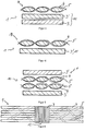
- Fig. 2 is a sectional view of a fiber preform 1 shown in a region in which the first fiber structure 10 from Fig. 1 a second fiber structure 11, formed from the wound fibers 3, 3 ', is arranged.
- the wound fibers 3 have an orientation of -45 °, the wound fibers 3 'an orientation of + 45 °.
- Fig. 2 shows a kind of sandwich construction with a triaxial fiber structure 10 as a core and these surrounding wound fibers 3, 3 '.
- Fig. 3 to 5 show further possible embodiments, wherein in Fig. 3 the fiber preform 1 with two wound fiber structures 3, 3 'are arranged on one side of the braided fiber structure 10.
- This can be achieved by first producing the fiber preform 1 to be produced with the braided fiber structure 10 and the wound fibers 3 ', wherein subsequently an additional fiber layer is supplemented by the wound fibers 3.
- the braided fiber structure 10 forms the 0 ° orientation
- the wound fiber structure 11 has fibers 3 ', 3 of -80 and + 80 °.
- the 4 and 5 show further alternative embodiments for the arrangement of braided fiber structures 10 and wound fiber structures 11 in a two- and four-layer formation.
- the too Fig. 2 and 3 described features are applicable accordingly in this regard.
- FIG. 3 shows a plan view of a finished fiber preform 1, in which the braided fiber structure 10 extends over the entire length and the second, wound fiber structure 11 is arranged locally limited in a region 12 around which Transverse force absorption capacity of the fiber preform 1 or to increase the fiber composite component to be produced in this area 12.
- FIGS. 7 and 8 show a manufacturing plant, with which a fiber preform 1 with a braided fiber structure 10 and a locally limited wound fiber structure 11, which are generated simultaneously, can be produced.
- the fiber preform 1 to be manufactured has a predetermined take-off speed which influences the orientation of the braided fibers and the wound fibers.
- two winding systems 30 and 31 are provided to each produce a wound fiber structure with positive and negative orientation.
- the braided fiber structures of carbon fibers 4 and braiding fibers 5 extend over the entire length of the fiber preform 1.
- Fig. 7 the part of the method is shown, in which additionally the second, wound fiber structure is applied to the fiber preform 1.
- the fibers from the first and second winding system 30, 31 are pressed during insertion on the fiber preform 1 until the fibers have sufficient independent adhesion to the component.
- About the pressure rollers 40 or another system, not shown, is thermally acted upon to be wound fibers to ensure additional fixation to the fiber preform 1. This applies both during insertion and during the subsequent settling or cutting off of the wound fiber structure.
- Parallel to the braiding process of the first fiber structure 10 formed from carbon fibers 4 and braiding fibers 5, fibers 33, 34 are wound around the fiber preform 1 to be produced by the winding systems 30, 31, wherein the fiber orientation of the wound fibers exceeds the rotational speed of the winding systems 30, 31, which are preferably designed as coils, is determined. The greater the angles of the fiber orientation, the faster the winding systems 30, 31 have to be guided around the fiber preform.
- the invention is not limited in its execution to the above-mentioned preferred embodiments. Rather, a number of variants is conceivable, which makes use of the illustrated solution even with fundamentally different types of use.
- different fiber types such as carbon fibers, aramid fibers or glass fibers are combined.
- the fibers may already be pre-bindered or impregnated.
- weaves of tethered Tows are included as a material.
Landscapes
- Engineering & Computer Science (AREA)
- Textile Engineering (AREA)
- Mechanical Engineering (AREA)
- Manufacturing & Machinery (AREA)
- Braiding, Manufacturing Of Bobbin-Net Or Lace, And Manufacturing Of Nets By Knotting (AREA)
- Reinforced Plastic Materials (AREA)
- Moulding By Coating Moulds (AREA)
- Woven Fabrics (AREA)
Description
- Die Erfindung betrifft ein Verfahren zur Herstellung eines Faser-Preforms für ein Faserverbundbauteil, insbesondere eines Hohlprofils, wobei eine erste Faserstruktur in einem Flechtprozess geflochten und eine zweite Faserstruktur in einem Wickelprozess gewickelt wird.
- Aus dem Stand der Technik sind Flecht- und Umflechtprozesse für die Herstellung von Biaxial- und Triaxial-Geflechten zur Erzeugung von Faser-Preforms unter Verwendung von verschiedenen Faserarten, insbesondere Glasfasern, Kohlenstofffasern, Aramidfasern sowie Kombinationen daraus, bekannt. Solche und ähnliche Verfahren sind beispielsweise aus den Offenbarungen der Schriften
US 5 979 288 A ,WO 95/30532 A1 FR 1 200 649 A FR 2 954 210 A1 WO 90/15712 A1 DE 10 2008 052 671 B3 bekannt. Der Flechtprozess ist besonders günstig zur Ausbildung der 0°-Orientierung, d.h. der Orientierung entlang der Längsachse des zu fertigenden Bauteils, auch bei komplexen Bauteilgeometrien, da ein Abrutschen bzw. ein Versatz der Fasern durch die Queranbindung mit Flechtfasern reduziert wird. Auch das Wickeln von Fasern zur Erzeugung von Bauteilen ist grundsätzlich aus dem Stand der Technik bekannt. Der Wickelprozess wird jedoch hauptsächlich für rotationssymmetrische Bauteile mit einfachen Bauteilgeometrien eingesetzt, da durch das Wickeln gegenüber einem Flechtprozess sehr gut große Winkel gegenüber der 0°-Orientierung, d.h. insbesondere in Umfangsrichtung, sehr gut realisierbar sind. Die 0°-Faserorientierung ist durch den Wickelprozess alleine kaum oder nur sehr eingeschränkt erzeugbar. Die Flechtverfahren unterliegen ebenfalls Einschränkungen hinsichtlich der Variabilität, da speziell bei triaxialen Aufbauten große Winkel gegenüber der 0°-Orientierung nur mit großen Querschnitten umsetzbar sind. Zudem sinkt die Produktionsgeschwindigkeit im Flechtprozess bei großen Winkeln erheblich. Auch das verwendbare Fasermaterial ist durch die Spulengröße für die Flechtfäden und die Ondulation der Fasern beschränkt. Es müssten Fasern mit geringer Fadenfeinheit eingesetzt werden, wodurch die Kosten, insbesondere beim Einsatz von Kohlenstofffasern, deutlich erhöht werden. - Vor diesem Hintergrund ist es Aufgabe der Erfindung, ein Verfahren bereit zu stellen, mit dem Faser-Preforms herstellbar sind, deren lokale mechanische Eigenschaften über den Herstellprozess einstellbar sind.
- Diese Aufgabe wird gemäß den Merkmalen des Anspruchs 1 gelöst. Das Verfahren zur Herstellung eines Faser-Preforms für ein Faserverbundbauteil gemäß Patentanspruch 1 sieht vor, dass über die gesamte Länge des zu erzeugenden Faser-Preforms mindestens eine erste Faserstruktur in einem Flechtprozess geflochten und über einen Teil der Länge des zu erzeugenden Faser-Preforms mindestens eine zweite Faserstruktur in einem Wickelprozess gewickelt wird. In einer günstigen Ausführung erfolgen dabei der Wickelprozess und der Flechtprozess gleichzeitig. Das Faser-Preform bildet die Grundlage für das zu fertigende Faserverbundbauteil, wobei die Weiterverarbeitung des Faser-Preforms beispielsweise im RTM-Verfahren erfolgt.
- Die mechanischen Eigenschaften in Längsrichtung, d.h. entlang der 0°-Orientierung, wird durch die geflochtene Faserstruktur bestimmt, wobei an lokal spezifischen Bereichen die mechanischen Quereigenschaften durch die zweite, gewickelte Faserstruktur festlegbar ist. Das auf diese Weise hergestellte Bauteil kann somit verschiedene Anforderungen erfüllen. Die Kraftaufnahme und -übertragung in Längsrichtung entlang der 0°-Orientierung wird ergänzt durch lokal im Bereich der gewickelten Faserstruktur erhöhte Kraftaufnahmekapazitäten in Querrichtung, beispielsweise zur Erhöhung der Crash-Stabilität des Bauteils in Querrichtung. Um das Gewicht und die Kosten des Bauteils nicht übermäßig zu erhöhen, ist erfindungsgemäß vorgesehen, dass der Wickelprozess der zweiten Faserstruktur erst einsetzt, nachdem die erste Faserstruktur in dem Flechtprozess bereits über eine vorbestimmte Länge geflochten wurde, so dass nur der tatsächlich benötigte Bereich des zu fertigenden Faser-Preforms mit der gewickelten Faserstruktur versehen und nur in diesem Bereich die lokal erhöhten Kraftaufnahmekapazitäten in Querrichtung erzielt werden. Diese effiziente Ausnutzung des Fasermaterials beschränkt die materialbedingten Kosten und reduziert das Gewicht des zu fertigenden Faser-Preforms.
- Erfindungsgemäß ist ferner vorgesehen, dass der Wickelprozess in den laufenden Flechtprozess eingefügt und aus dem laufenden Flechtprozess abgesetzt wird. Hierzu kann die Wickeleinheit an der Flechtmaschine integriert und so ausgelegt sein, dass die Fasern lokal auf dem zu fertigenden Faser-Preform an- bzw. abgesetzt werden können. Vorteilhafterweise weist die Fertigungsanlage hierfür spezielle Andrückrollen auf, mit denen die zu wickelnde Faserstruktur an das Faser-Preform angedrückt werden, bis die Faserreibung untereinander ausreicht, dass sich diese selbstständig fixieren. Zum Absetzen der gewickelten Faserstruktur werden die Fasern mit einem Schneidmesser getrennt und über die Andrückrollen an dem Faser-Preform befestigt. Hierfür ist in einer Ausführungsform der Erfindung vorgesehen, dass die Faserenden durch thermische Einwirkung und über eine Art Klebstoff (z. B. Sprühkleber, Klebebänder etc.) an dem zu fertigenden Bauteil fixiert werden. Beispielsweise können hierzu die Andrückrollen entsprechend aufgeheizt und mit einer Sprühklebevorrichtung ausgestattet sein. Die Befestigung erfolgt somit über eine Aktivierung von vorab in die Fasern eingebrachtem Binder. Ferner ist möglich, das sog.
- Fiber-Placement-Verfahren anzuwenden.
- Der Flechtprozess ist nicht auf eine Faserorientierung von 0° beschränkt, es ist auch möglich, Faserorientierungen von ±45° zu flechten, wobei zusätzlich der Wickelprozess mit noch größeren Winkeln integriert wird. Die Faserorientierung der gewickelten Fasern liegt in einem Bereich von ±30 bis ±80°, insbesondere ±45 bis ±80°. In einer hinsichtlich der Produktionsgeschwindigkeit günstigen Ausführung werden die geflochtenen Fasern für die 0°-Orientierung und die gewickelten Fasern für eine Faserorientierung von ±30 bis ±80° verwendet. Positive und negative Faserwinkel werden jeweils durch die Drehrichtung der Wicklung eingestellt.
- Andere vorteilhafte Weiterbildungen der Erfindung sind in den Unteransprüchen gekennzeichnet bzw. werden nachstehend zusammen mit der Beschreibung der bevorzugten Ausführung der Erfindung anhand der Figuren näher dargestellt. Es zeigen:
- Fig. 1:
- Eine Draufsicht auf eine triaxiale Flechtstruktur gemäß dem Stand der Technik;
- Fig. 2
- eine Schnittansicht eines Faser-Preforms mit geflochtener und gewickelter Faserstruktur in einer ersten Ausführungsform;
- Fig. 3
- eine Schnittansicht eines Faser-Preforms mit geflochtener und gewickelter Faserstruktur in einer zweiten Ausführungsform;
- Fig. 4
- eine Schnittansicht eines Faser-Preforms mit geflochtener und gewickelter Faserstruktur in einer dritten Ausführungsform;
- Fig. 5
- eine Schnittansicht eines Faser-Preforms mit geflochtener und gewickelter Faserstruktur in einer vierten Ausführungsform;
- Fig. 6
- eine Draufsicht auf ein erfindungsgemäßes Faser-Preform;
- Fig. 7
- eine Anlage zur Durchführung des Verfahrens und Herstellung des Faser-Preforms; und
- Fig. 8
- eine Seitenansicht der Anlage aus
Fig. 7 - Die Figuren sind beispielhaft schematisch. In allen Ansichten bezeichnen gleiche Bezugszeichen gleiche Bauteile.
-
Fig. 1 zeigt die aus dem Stand der Technik bekannte triaxial geflochtene Faserstruktur 10 mit dicken Kohlenstofffasern 4 und dünnen Flechtfasern 5, wobei die Flechtfasern 5 in einem vorbestimmten Winkel um die Kohlenstofffasern 4 geflochten sind. Die Flechtfasern 5 dienen als Fixierung der Kohlenstofffasern 4. - In
Fig. 2 ist eine Schnittansicht eines Faser-Preforms 1 in einem Bereich dargestellt, bei dem um die erste Faserstruktur 10 ausFig. 1 eine zweite Faserstruktur 11, gebildet aus den gewickelten Fasern 3, 3', angeordnet ist. In der gezeigten Ausführung weisen die gewickelten Fasern 3 eine Orientierung von -45°, die gewickelten Fasern 3' eine Orientierung von +45° auf.Fig. 2 zeigt eine Art Sandwich-Bauweise mit einer triaxialen Faserstruktur 10 als Kern und diese umgebende gewickelte Fasern 3, 3'. - Die
Fig. 3 bis 5 zeigen weitere mögliche Ausführungsformen, wobei inFig. 3 das Faser-Preform 1 mit zwei gewickelten Faserstrukturen 3, 3' auf einer Seite der geflochtenen Faserstruktur 10 angeordnet sind. Dies ist erzielbar, indem das zu fertigende Faser-Preform 1 zunächst mit der geflochtenen Faserstruktur 10 und den gewickelten Fasern 3' gefertigt wird, wobei anschließend eine zusätzliche Faserlage durch die gewickelten Fasern 3 ergänzt wird. Die geflochtene Faserstruktur 10 bildet die 0°-Orientierung, die gewickelte Faserstruktur 11 weist Fasern 3', 3 von -80 und +80° auf. - Die
Fig. 4 und 5 zeigen weitere alternative Ausführungsbeispiele zur Anordnung von geflochtenen Faserstrukturen 10 und gewickelten Faserstrukturen 11 in einer zwei- und vierlagigen Ausbildung. Die zuFig. 2 und3 beschriebenen Merkmale sind diesbezüglich entsprechend anwendbar. - In
Fig. 6 ist eine Draufsicht auf ein fertiges Faser-Preform 1 gezeigt, bei dem sich die geflochtene Faserstruktur 10 über die gesamte Länge erstreckt und die zweite, gewickelte Faserstruktur 11 lokal begrenzt in einem Bereich 12 angeordnet ist, um die Querkraftaufnahmekapazität des Faser-Preforms 1 bzw. das hieraus zu fertigenden Faserverbundbauteils in diesem Bereich 12 zu erhöhen. - Die
Fig. 7 und 8 zeigen eine Fertigungsanlage, mit der ein Faser-Preform 1 mit einer geflochtenen Faserstruktur 10 und einer lokal begrenzten gewickelten Faserstruktur 11, die gleichzeitig erzeugt werden, herstellbar ist. Das zu fertigende Faser-Preform 1 weist eine vorbestimmte Abzugsgeschwindigkeit auf, welche die Orientierung der geflochtenen Fasern und der gewickelten Fasern beeinflusst. Bei der gezeigten Anlage sind zwei Wickelsysteme 30 und 31 vorgesehen, um je eine gewickelte Faserstruktur mit positiver und negativer Orientierung zu erzeugen. Die geflochtenen Faserstrukturen aus Kohlenstofffasern 4 und Flechtfasern 5 erstrecken sich über die gesamte Länge des Faser-Preforms 1. InFig. 7 ist der Teil des Verfahrens dargestellt, in dem zusätzlich die zweite, gewickelte Faserstruktur auf den Faser-Preform 1 aufgebracht wird. Über Andrückrollen 40 werden die Fasern aus dem ersten und zweiten Wickelsystem 30, 31 beim Einsetzen an das Faser-Preform 1 angedrückt, bis die Fasern eine ausreichende selbstständige Haftung an dem Bauteil aufweisen. Über die Andrückrollen 40 oder ein weiteres nicht dargestelltes System wird thermisch auf die zu wickelnden Fasern eingewirkt, um eine zusätzliche Fixierung an dem Faser-Preform 1 zu gewährleisten. Dies gilt sowohl bei dem Einsetzen als auch bei dem späteren Absetzen bzw. Abschneiden der gewickelten Faserstruktur. Parallel zu dem Flechtprozess der ersten, aus Kohlenstofffasern 4 und Flechtfasern 5 gebildeten Faserstruktur 10 werden von den Wickelsystemen 30, 31 Fasern 33, 34 um das zu fertigende Faser-Preform 1 gewickelt, wobei die Faserorientierung der gewickelten Fasern über die Rotationsgeschwindigkeit der Wickelsysteme 30, 31, die vorzugweise als Spulen ausgebildet sind, bestimmt wird. Je größer die Winkel der Faserorientierung sein sollen, desto schneller müssen die Wickelsysteme 30, 31 um das Faser-Preform herumgeführt werden. - Die Erfindung beschränkt sich in ihrer Ausführung nicht auf die vorstehend angegebenen bevorzugten Ausführungsbeispiele. Vielmehr ist eine Anzahl von Varianten denkbar, welche von der dargestellten Lösung auch bei grundsätzlich anders gearteten Ausführungen Gebrauch macht. Beispielsweise können unterschiedliche Faserarten, wie Kohlenstofffasern, Aramidfasern oder Glasfasern kombiniert werden. Zusätzlich können die Fasern vorab bereits mit einem Binder versehen oder imprägniert sein. Auch sind Flechtungen von bebinderten Tows als Material mit umfasst.
Claims (5)
- Verfahren zur Herstellung eines Faser-Preforms (1) für ein Faserverbundbauteil, wobei über die gesamte Länge des zu erzeugenden Faser-Preforms (1) mindestens eine erste Faserstruktur (10) in einem Flechtprozess geflochten und über einen Teil der Länge des zu erzeugenden Faser-Preforms (1) mindestens eine zweite Faserstruktur (11) in einem Wickelprozess gewickelt wird dadurch gekennzeichnet, dassder Wickelprozess in den laufenden Flechtprozess eingefügt und aus dem laufenden Flechtprozess abgesetzt wird,die Fasern der zweiten, gewickelten Faserstruktur (11) zum Absetzen der zweiten, gewickelten Faserstruktur (11) mit einem Schneidmesser getrennt werden unddie zweite, gewickelte Faserstruktur (11) zumindest zeitweise über Andrückrollen (40) an das Faser-Preform (1) gedrückt wird, wobeiFaserenden der Fasern der zweiten, gewickelten Faserstruktur (11) mit Klebstoff versehen werden unddie Andrückrollen (40) heizbar sind und die mit Klebstoff versehenen Faserenden durch die Andrückrollen (40) thermisch aktiviert und fixiert werden.
- Verfahren nach Anspruch 1, dadurch gekennzeichnet, dass der Wickelprozess und der Flechtprozess gleichzeitig erfolgen, wobei der Wickelprozess einsetzt, nachdem die erste Faserstruktur (10) in dem Flechtprozess bereits über eine vorbestimmte Länge geflochten wurde.
- Verfahren nach zumindest einem der vorigen Ansprüche, dadurch gekennzeichnet, dass der Flechtprozess eine Faserorientierung von 0° erzeugt oder eine Faserorientierung von ±45° erzeugt.
- Verfahren nach zumindest einem der vorigen Ansprüche, dadurch gekennzeichnet, dass der Wickelprozess eine Faserorientierung von ±30 bis ± 80°erzeugt.
- Verfahren nach zumindest einem der vorigen Ansprüche, dadurch gekennzeichnet, dass Fasern (4, 5) der ersten Faserstruktur (10) vorimprägniert oder bebindert sind.
Applications Claiming Priority (2)
| Application Number | Priority Date | Filing Date | Title |
|---|---|---|---|
| DE102013218006.3A DE102013218006A1 (de) | 2013-09-09 | 2013-09-09 | Verfahren zur Herstellung von Faser-Preforms für ein Faserverbundbauteil mit lokal angepassten mechanischen Eigenschaften |
| PCT/EP2014/067982 WO2015032644A1 (de) | 2013-09-09 | 2014-08-25 | Verfahren zur herstellung von faser-preforms für ein faserverbundbauteil mit lokal angepassten mechanischen eigenschaften |
Publications (2)
| Publication Number | Publication Date |
|---|---|
| EP3043975A1 EP3043975A1 (de) | 2016-07-20 |
| EP3043975B1 true EP3043975B1 (de) | 2019-08-14 |
Family
ID=51492925
Family Applications (1)
| Application Number | Title | Priority Date | Filing Date |
|---|---|---|---|
| EP14761296.4A Active EP3043975B1 (de) | 2013-09-09 | 2014-08-25 | Verfahren zur herstellung von faser-preforms für ein faserverbundbauteil mit lokal angepassten mechanischen eigenschaften |
Country Status (5)
| Country | Link |
|---|---|
| US (1) | US10184197B2 (de) |
| EP (1) | EP3043975B1 (de) |
| CN (1) | CN105283284B (de) |
| DE (1) | DE102013218006A1 (de) |
| WO (1) | WO2015032644A1 (de) |
Families Citing this family (1)
| Publication number | Priority date | Publication date | Assignee | Title |
|---|---|---|---|---|
| DE102015209535A1 (de) | 2015-05-22 | 2016-11-24 | Bayerische Motoren Werke Aktiengesellschaft | Verfahren und Vorrichtung zur Herstellung eines Faserhalbzeugs, Faserhalbzeug und Verfahren zur Herstellung eines faserverstärkten Kunststoffbauteils |
Citations (1)
| Publication number | Priority date | Publication date | Assignee | Title |
|---|---|---|---|---|
| DE102008052671B3 (de) * | 2008-10-22 | 2010-06-17 | Eads Deutschland Gmbh | Flechtvorrichtung und Verfahren zum Beflechten eines Flechtkerns |
Family Cites Families (10)
| Publication number | Priority date | Publication date | Assignee | Title |
|---|---|---|---|---|
| BE569803A (de) * | 1957-07-26 | 1900-01-01 | ||
| US4304169A (en) * | 1979-07-26 | 1981-12-08 | The B. F. Goodrich Company | Braiding machine |
| US5127783A (en) * | 1989-05-25 | 1992-07-07 | The B.F. Goodrich Company | Carbon/carbon composite fasteners |
| US5048441A (en) * | 1989-06-15 | 1991-09-17 | Fiberspar, Inc. | Composite sail mast with high bending strength |
| US5203249A (en) * | 1991-08-30 | 1993-04-20 | United Technologies Corporation | Multiple mandrel/braiding ring braider |
| WO1995030532A1 (en) * | 1994-05-04 | 1995-11-16 | Composite Development Corporation | Structure and method of manufacture of high strength, high stiffness, curved composite member |
| US5979288A (en) * | 1998-05-18 | 1999-11-09 | Fiberspar Spoolable Products, Inc. | Helical braider |
| CN1919587A (zh) * | 2005-08-25 | 2007-02-28 | 深圳市海川实业股份有限公司 | 一种增加纤维增强树脂拉挤型材横向强度的方法及其产品 |
| DE102008052670B4 (de) * | 2008-10-22 | 2017-12-14 | Airbus Defence and Space GmbH | Flechtvorrichtung und Flechtverfahren zum Beflechten eines Flechtkerns |
| FR2954210B1 (fr) * | 2009-12-18 | 2012-06-15 | Messier Dowty Sa | Procede de fabrication d'une piece en materiau composite obtenue par depot de couches de fibres renforcantes plaquees sur un mandrin |
-
2013
- 2013-09-09 DE DE102013218006.3A patent/DE102013218006A1/de active Granted
-
2014
- 2014-08-25 WO PCT/EP2014/067982 patent/WO2015032644A1/de not_active Ceased
- 2014-08-25 CN CN201480034034.0A patent/CN105283284B/zh active Active
- 2014-08-25 EP EP14761296.4A patent/EP3043975B1/de active Active
-
2016
- 2016-01-13 US US14/994,727 patent/US10184197B2/en active Active
Patent Citations (1)
| Publication number | Priority date | Publication date | Assignee | Title |
|---|---|---|---|---|
| DE102008052671B3 (de) * | 2008-10-22 | 2010-06-17 | Eads Deutschland Gmbh | Flechtvorrichtung und Verfahren zum Beflechten eines Flechtkerns |
Non-Patent Citations (1)
| Title |
|---|
| CAMPBELL F C ED - CAMPBELL FLAKE C: "Manufacturing processes for advanced composites", 1 January 2004, MANUFACTURING PROCESSES FOR ADVANCED COMPOSITES, ELSEVIER ADVANCED TECHNOLOGY, OXFORD, GB, PAGE(S) 304 - 356, ISBN: 978-1-85617-415-2, XP002580602 * |
Also Published As
| Publication number | Publication date |
|---|---|
| EP3043975A1 (de) | 2016-07-20 |
| US10184197B2 (en) | 2019-01-22 |
| CN105283284B (zh) | 2019-01-01 |
| CN105283284A (zh) | 2016-01-27 |
| US20160122917A1 (en) | 2016-05-05 |
| DE102013218006A1 (de) | 2015-03-12 |
| WO2015032644A1 (de) | 2015-03-12 |
Similar Documents
| Publication | Publication Date | Title |
|---|---|---|
| EP2646226B1 (de) | Unidirektionale faserbänder aufweisender faservorformling aus verstärkungsfaserbündeln und verbundwerkstoff-bauteil | |
| EP1798428B1 (de) | Flechttechnisch hergestelltes Faserverbundbauteil | |
| EP2296873B1 (de) | Verfahren zur herstellung eines beidseitig mit deckschichten versehenen kernverbundes | |
| EP1342553B1 (de) | Verfahren zum Herstellen eines Fensterrahmens für Flugzeuge aus faserverstärktem Kunststoff und Vorrichtung zur Durchführung des Verfahrens | |
| DE102008028865B4 (de) | Verfahren zur Herstellung von Faserverbund-Profilbauteilen, sowie Verwendung derartig hergestellter Faserverbund-Profilbauteile | |
| DE102010005987B4 (de) | Verfahren zur Herstellung von Hohlkörpern mit bundförmigen Verstärkungen | |
| DE102010042128A1 (de) | Strukturbauteil, Luft- oder Raumfahrzeug sowie Verfahren | |
| DE102008063545A1 (de) | Multiaxialgelege | |
| WO2008012300A1 (de) | Antenne in einem faserverstärkten verbundwerkstoff und verfahren zur ausbildung einer antenne in einem faserverstärkten verbundwerkstoff | |
| EP2370315A2 (de) | Flächiges bauteil eines fluggerätes und verfahren zu dessen herstellung | |
| EP2447401B1 (de) | Partiell fixiertes textiles Halbzeug | |
| EP3142843B1 (de) | Verfahren zur herstellung eines dämpferrohres aus einem faserverbundwerkstoff für einen schwingungsdämpfer | |
| DE102012001055B4 (de) | Bauteil | |
| DE102015000947A1 (de) | Verfahren zur Herstellung eines faserverstärkten Polymer-Formteils mit einer Mehrzahl an Verstärkungsfaserlagen und Vorformling eines solchen Polymer-Formteils | |
| WO2015032644A1 (de) | Verfahren zur herstellung von faser-preforms für ein faserverbundbauteil mit lokal angepassten mechanischen eigenschaften | |
| DE102009053289A1 (de) | Verfahren zur Herstellung eines textilen Halbzeuges sowie textiles Halbzeug für eine textile Faserverbundstruktur | |
| WO2015104178A1 (de) | Faserverbundwerkstoff und verfahren zu dessen herstellung | |
| DE10205657C2 (de) | Verfahren zur Herstellung einer rohrförmigen, torsions-und biegesteifen Antriebswelle | |
| EP2873518B1 (de) | Verfahren zum Herstellen eines verstärkten Faserverbundbauteils | |
| DE102012206384B4 (de) | Faser-Flechtprofil | |
| DE102007044276A1 (de) | Zugstrebe einer Seitenaufprallschutz-Anordnung | |
| EP4051490A1 (de) | Komponente aus einem faserverstärkten kunststoff mit reduzierter aufziehspannung und verfahren zu deren herstellung | |
| EP2650418B1 (de) | Verfahren zur Herstellung von gekrümmten Faserhalbzeugen | |
| DE102011107512A1 (de) | Duktile CFK-Struktur | |
| DE102018105246B4 (de) | Verfahren zur Herstellung eines verstärkten Faserverbundwerkstoffs, Faserverbundwerkstoff und Luft- oder Raumfahrzeug |
Legal Events
| Date | Code | Title | Description |
|---|---|---|---|
| PUAI | Public reference made under article 153(3) epc to a published international application that has entered the european phase |
Free format text: ORIGINAL CODE: 0009012 |
|
| 17P | Request for examination filed |
Effective date: 20160119 |
|
| AK | Designated contracting states |
Kind code of ref document: A1 Designated state(s): AL AT BE BG CH CY CZ DE DK EE ES FI FR GB GR HR HU IE IS IT LI LT LU LV MC MK MT NL NO PL PT RO RS SE SI SK SM TR |
|
| AX | Request for extension of the european patent |
Extension state: BA ME |
|
| DAX | Request for extension of the european patent (deleted) | ||
| STAA | Information on the status of an ep patent application or granted ep patent |
Free format text: STATUS: EXAMINATION IS IN PROGRESS |
|
| 17Q | First examination report despatched |
Effective date: 20171018 |
|
| GRAP | Despatch of communication of intention to grant a patent |
Free format text: ORIGINAL CODE: EPIDOSNIGR1 |
|
| STAA | Information on the status of an ep patent application or granted ep patent |
Free format text: STATUS: GRANT OF PATENT IS INTENDED |
|
| INTG | Intention to grant announced |
Effective date: 20190430 |
|
| GRAS | Grant fee paid |
Free format text: ORIGINAL CODE: EPIDOSNIGR3 |
|
| GRAA | (expected) grant |
Free format text: ORIGINAL CODE: 0009210 |
|
| STAA | Information on the status of an ep patent application or granted ep patent |
Free format text: STATUS: THE PATENT HAS BEEN GRANTED |
|
| AK | Designated contracting states |
Kind code of ref document: B1 Designated state(s): AL AT BE BG CH CY CZ DE DK EE ES FI FR GB GR HR HU IE IS IT LI LT LU LV MC MK MT NL NO PL PT RO RS SE SI SK SM TR |
|
| REG | Reference to a national code |
Ref country code: GB Ref legal event code: FG4D Free format text: NOT ENGLISH |
|
| REG | Reference to a national code |
Ref country code: CH Ref legal event code: EP Ref country code: AT Ref legal event code: REF Ref document number: 1166498 Country of ref document: AT Kind code of ref document: T Effective date: 20190815 |
|
| REG | Reference to a national code |
Ref country code: DE Ref legal event code: R096 Ref document number: 502014012424 Country of ref document: DE |
|
| REG | Reference to a national code |
Ref country code: IE Ref legal event code: FG4D Free format text: LANGUAGE OF EP DOCUMENT: GERMAN |
|
| REG | Reference to a national code |
Ref country code: NL Ref legal event code: MP Effective date: 20190814 |
|
| REG | Reference to a national code |
Ref country code: LT Ref legal event code: MG4D |
|
| PG25 | Lapsed in a contracting state [announced via postgrant information from national office to epo] |
Ref country code: FI Free format text: LAPSE BECAUSE OF FAILURE TO SUBMIT A TRANSLATION OF THE DESCRIPTION OR TO PAY THE FEE WITHIN THE PRESCRIBED TIME-LIMIT Effective date: 20190814 Ref country code: NO Free format text: LAPSE BECAUSE OF FAILURE TO SUBMIT A TRANSLATION OF THE DESCRIPTION OR TO PAY THE FEE WITHIN THE PRESCRIBED TIME-LIMIT Effective date: 20191114 Ref country code: BG Free format text: LAPSE BECAUSE OF FAILURE TO SUBMIT A TRANSLATION OF THE DESCRIPTION OR TO PAY THE FEE WITHIN THE PRESCRIBED TIME-LIMIT Effective date: 20191114 Ref country code: NL Free format text: LAPSE BECAUSE OF FAILURE TO SUBMIT A TRANSLATION OF THE DESCRIPTION OR TO PAY THE FEE WITHIN THE PRESCRIBED TIME-LIMIT Effective date: 20190814 Ref country code: SE Free format text: LAPSE BECAUSE OF FAILURE TO SUBMIT A TRANSLATION OF THE DESCRIPTION OR TO PAY THE FEE WITHIN THE PRESCRIBED TIME-LIMIT Effective date: 20190814 Ref country code: LT Free format text: LAPSE BECAUSE OF FAILURE TO SUBMIT A TRANSLATION OF THE DESCRIPTION OR TO PAY THE FEE WITHIN THE PRESCRIBED TIME-LIMIT Effective date: 20190814 Ref country code: HR Free format text: LAPSE BECAUSE OF FAILURE TO SUBMIT A TRANSLATION OF THE DESCRIPTION OR TO PAY THE FEE WITHIN THE PRESCRIBED TIME-LIMIT Effective date: 20190814 Ref country code: PT Free format text: LAPSE BECAUSE OF FAILURE TO SUBMIT A TRANSLATION OF THE DESCRIPTION OR TO PAY THE FEE WITHIN THE PRESCRIBED TIME-LIMIT Effective date: 20191216 |
|
| PG25 | Lapsed in a contracting state [announced via postgrant information from national office to epo] |
Ref country code: RS Free format text: LAPSE BECAUSE OF FAILURE TO SUBMIT A TRANSLATION OF THE DESCRIPTION OR TO PAY THE FEE WITHIN THE PRESCRIBED TIME-LIMIT Effective date: 20190814 Ref country code: LV Free format text: LAPSE BECAUSE OF FAILURE TO SUBMIT A TRANSLATION OF THE DESCRIPTION OR TO PAY THE FEE WITHIN THE PRESCRIBED TIME-LIMIT Effective date: 20190814 Ref country code: AL Free format text: LAPSE BECAUSE OF FAILURE TO SUBMIT A TRANSLATION OF THE DESCRIPTION OR TO PAY THE FEE WITHIN THE PRESCRIBED TIME-LIMIT Effective date: 20190814 Ref country code: GR Free format text: LAPSE BECAUSE OF FAILURE TO SUBMIT A TRANSLATION OF THE DESCRIPTION OR TO PAY THE FEE WITHIN THE PRESCRIBED TIME-LIMIT Effective date: 20191115 Ref country code: ES Free format text: LAPSE BECAUSE OF FAILURE TO SUBMIT A TRANSLATION OF THE DESCRIPTION OR TO PAY THE FEE WITHIN THE PRESCRIBED TIME-LIMIT Effective date: 20190814 Ref country code: IS Free format text: LAPSE BECAUSE OF FAILURE TO SUBMIT A TRANSLATION OF THE DESCRIPTION OR TO PAY THE FEE WITHIN THE PRESCRIBED TIME-LIMIT Effective date: 20191214 |
|
| PG25 | Lapsed in a contracting state [announced via postgrant information from national office to epo] |
Ref country code: TR Free format text: LAPSE BECAUSE OF FAILURE TO SUBMIT A TRANSLATION OF THE DESCRIPTION OR TO PAY THE FEE WITHIN THE PRESCRIBED TIME-LIMIT Effective date: 20190814 |
|
| PG25 | Lapsed in a contracting state [announced via postgrant information from national office to epo] |
Ref country code: PL Free format text: LAPSE BECAUSE OF FAILURE TO SUBMIT A TRANSLATION OF THE DESCRIPTION OR TO PAY THE FEE WITHIN THE PRESCRIBED TIME-LIMIT Effective date: 20190814 Ref country code: DK Free format text: LAPSE BECAUSE OF FAILURE TO SUBMIT A TRANSLATION OF THE DESCRIPTION OR TO PAY THE FEE WITHIN THE PRESCRIBED TIME-LIMIT Effective date: 20190814 Ref country code: RO Free format text: LAPSE BECAUSE OF FAILURE TO SUBMIT A TRANSLATION OF THE DESCRIPTION OR TO PAY THE FEE WITHIN THE PRESCRIBED TIME-LIMIT Effective date: 20190814 Ref country code: EE Free format text: LAPSE BECAUSE OF FAILURE TO SUBMIT A TRANSLATION OF THE DESCRIPTION OR TO PAY THE FEE WITHIN THE PRESCRIBED TIME-LIMIT Effective date: 20190814 |
|
| PG25 | Lapsed in a contracting state [announced via postgrant information from national office to epo] |
Ref country code: SK Free format text: LAPSE BECAUSE OF FAILURE TO SUBMIT A TRANSLATION OF THE DESCRIPTION OR TO PAY THE FEE WITHIN THE PRESCRIBED TIME-LIMIT Effective date: 20190814 Ref country code: LI Free format text: LAPSE BECAUSE OF NON-PAYMENT OF DUE FEES Effective date: 20190831 Ref country code: LU Free format text: LAPSE BECAUSE OF NON-PAYMENT OF DUE FEES Effective date: 20190825 Ref country code: SM Free format text: LAPSE BECAUSE OF FAILURE TO SUBMIT A TRANSLATION OF THE DESCRIPTION OR TO PAY THE FEE WITHIN THE PRESCRIBED TIME-LIMIT Effective date: 20190814 Ref country code: CH Free format text: LAPSE BECAUSE OF NON-PAYMENT OF DUE FEES Effective date: 20190831 Ref country code: CZ Free format text: LAPSE BECAUSE OF FAILURE TO SUBMIT A TRANSLATION OF THE DESCRIPTION OR TO PAY THE FEE WITHIN THE PRESCRIBED TIME-LIMIT Effective date: 20190814 Ref country code: IS Free format text: LAPSE BECAUSE OF FAILURE TO SUBMIT A TRANSLATION OF THE DESCRIPTION OR TO PAY THE FEE WITHIN THE PRESCRIBED TIME-LIMIT Effective date: 20200224 Ref country code: MC Free format text: LAPSE BECAUSE OF FAILURE TO SUBMIT A TRANSLATION OF THE DESCRIPTION OR TO PAY THE FEE WITHIN THE PRESCRIBED TIME-LIMIT Effective date: 20190814 |
|
| REG | Reference to a national code |
Ref country code: BE Ref legal event code: MM Effective date: 20190831 |
|
| REG | Reference to a national code |
Ref country code: DE Ref legal event code: R097 Ref document number: 502014012424 Country of ref document: DE |
|
| PLBE | No opposition filed within time limit |
Free format text: ORIGINAL CODE: 0009261 |
|
| STAA | Information on the status of an ep patent application or granted ep patent |
Free format text: STATUS: NO OPPOSITION FILED WITHIN TIME LIMIT |
|
| PG2D | Information on lapse in contracting state deleted |
Ref country code: IS |
|
| PG25 | Lapsed in a contracting state [announced via postgrant information from national office to epo] |
Ref country code: IE Free format text: LAPSE BECAUSE OF NON-PAYMENT OF DUE FEES Effective date: 20190825 |
|
| 26N | No opposition filed |
Effective date: 20200603 |
|
| PG25 | Lapsed in a contracting state [announced via postgrant information from national office to epo] |
Ref country code: BE Free format text: LAPSE BECAUSE OF NON-PAYMENT OF DUE FEES Effective date: 20190831 Ref country code: SI Free format text: LAPSE BECAUSE OF FAILURE TO SUBMIT A TRANSLATION OF THE DESCRIPTION OR TO PAY THE FEE WITHIN THE PRESCRIBED TIME-LIMIT Effective date: 20190814 |
|
| REG | Reference to a national code |
Ref country code: AT Ref legal event code: MM01 Ref document number: 1166498 Country of ref document: AT Kind code of ref document: T Effective date: 20190825 |
|
| PG25 | Lapsed in a contracting state [announced via postgrant information from national office to epo] |
Ref country code: AT Free format text: LAPSE BECAUSE OF NON-PAYMENT OF DUE FEES Effective date: 20190825 |
|
| PG25 | Lapsed in a contracting state [announced via postgrant information from national office to epo] |
Ref country code: CY Free format text: LAPSE BECAUSE OF FAILURE TO SUBMIT A TRANSLATION OF THE DESCRIPTION OR TO PAY THE FEE WITHIN THE PRESCRIBED TIME-LIMIT Effective date: 20190814 |
|
| PG25 | Lapsed in a contracting state [announced via postgrant information from national office to epo] |
Ref country code: HU Free format text: LAPSE BECAUSE OF FAILURE TO SUBMIT A TRANSLATION OF THE DESCRIPTION OR TO PAY THE FEE WITHIN THE PRESCRIBED TIME-LIMIT; INVALID AB INITIO Effective date: 20140825 Ref country code: MT Free format text: LAPSE BECAUSE OF FAILURE TO SUBMIT A TRANSLATION OF THE DESCRIPTION OR TO PAY THE FEE WITHIN THE PRESCRIBED TIME-LIMIT Effective date: 20190814 |
|
| PG25 | Lapsed in a contracting state [announced via postgrant information from national office to epo] |
Ref country code: MK Free format text: LAPSE BECAUSE OF FAILURE TO SUBMIT A TRANSLATION OF THE DESCRIPTION OR TO PAY THE FEE WITHIN THE PRESCRIBED TIME-LIMIT Effective date: 20190814 |
|
| P01 | Opt-out of the competence of the unified patent court (upc) registered |
Effective date: 20230502 |
|
| PGFP | Annual fee paid to national office [announced via postgrant information from national office to epo] |
Ref country code: DE Payment date: 20250731 Year of fee payment: 12 |
|
| PGFP | Annual fee paid to national office [announced via postgrant information from national office to epo] |
Ref country code: IT Payment date: 20250829 Year of fee payment: 12 |
|
| PGFP | Annual fee paid to national office [announced via postgrant information from national office to epo] |
Ref country code: GB Payment date: 20250822 Year of fee payment: 12 |
|
| PGFP | Annual fee paid to national office [announced via postgrant information from national office to epo] |
Ref country code: FR Payment date: 20250821 Year of fee payment: 12 |