EP3043952B1 - Orbitalschweissvorrichtung mit vereinfachtem spulenkopplungssystem - Google Patents
Orbitalschweissvorrichtung mit vereinfachtem spulenkopplungssystem Download PDFInfo
- Publication number
- EP3043952B1 EP3043952B1 EP14762025.6A EP14762025A EP3043952B1 EP 3043952 B1 EP3043952 B1 EP 3043952B1 EP 14762025 A EP14762025 A EP 14762025A EP 3043952 B1 EP3043952 B1 EP 3043952B1
- Authority
- EP
- European Patent Office
- Prior art keywords
- axis
- welding wire
- wire storage
- welding
- storage device
- Prior art date
- Legal status (The legal status is an assumption and is not a legal conclusion. Google has not performed a legal analysis and makes no representation as to the accuracy of the status listed.)
- Active
Links
Images



Classifications
-
- B—PERFORMING OPERATIONS; TRANSPORTING
- B23—MACHINE TOOLS; METAL-WORKING NOT OTHERWISE PROVIDED FOR
- B23K—SOLDERING OR UNSOLDERING; WELDING; CLADDING OR PLATING BY SOLDERING OR WELDING; CUTTING BY APPLYING HEAT LOCALLY, e.g. FLAME CUTTING; WORKING BY LASER BEAM
- B23K37/00—Auxiliary devices or processes, not specially adapted for a procedure covered by only one of the other main groups of this subclass
- B23K37/02—Carriages for supporting the welding or cutting element
- B23K37/0211—Carriages for supporting the welding or cutting element travelling on a guide member, e.g. rail, track
- B23K37/0217—Carriages for supporting the welding or cutting element travelling on a guide member, e.g. rail, track the guide member being fixed to the workpiece
-
- B—PERFORMING OPERATIONS; TRANSPORTING
- B23—MACHINE TOOLS; METAL-WORKING NOT OTHERWISE PROVIDED FOR
- B23K—SOLDERING OR UNSOLDERING; WELDING; CLADDING OR PLATING BY SOLDERING OR WELDING; CUTTING BY APPLYING HEAT LOCALLY, e.g. FLAME CUTTING; WORKING BY LASER BEAM
- B23K37/00—Auxiliary devices or processes, not specially adapted for a procedure covered by only one of the other main groups of this subclass
- B23K37/02—Carriages for supporting the welding or cutting element
- B23K37/027—Carriages for supporting the welding or cutting element for making circular cuts or welds
-
- B—PERFORMING OPERATIONS; TRANSPORTING
- B23—MACHINE TOOLS; METAL-WORKING NOT OTHERWISE PROVIDED FOR
- B23K—SOLDERING OR UNSOLDERING; WELDING; CLADDING OR PLATING BY SOLDERING OR WELDING; CUTTING BY APPLYING HEAT LOCALLY, e.g. FLAME CUTTING; WORKING BY LASER BEAM
- B23K37/00—Auxiliary devices or processes, not specially adapted for a procedure covered by only one of the other main groups of this subclass
- B23K37/02—Carriages for supporting the welding or cutting element
- B23K37/0282—Carriages forming part of a welding unit
-
- B—PERFORMING OPERATIONS; TRANSPORTING
- B23—MACHINE TOOLS; METAL-WORKING NOT OTHERWISE PROVIDED FOR
- B23K—SOLDERING OR UNSOLDERING; WELDING; CLADDING OR PLATING BY SOLDERING OR WELDING; CUTTING BY APPLYING HEAT LOCALLY, e.g. FLAME CUTTING; WORKING BY LASER BEAM
- B23K9/00—Arc welding or cutting
- B23K9/02—Seam welding; Backing means; Inserts
- B23K9/028—Seam welding; Backing means; Inserts for curved planar seams
- B23K9/0282—Seam welding; Backing means; Inserts for curved planar seams for welding tube sections
- B23K9/0286—Seam welding; Backing means; Inserts for curved planar seams for welding tube sections with an electrode moving around the fixed tube during the welding operation
-
- B—PERFORMING OPERATIONS; TRANSPORTING
- B23—MACHINE TOOLS; METAL-WORKING NOT OTHERWISE PROVIDED FOR
- B23K—SOLDERING OR UNSOLDERING; WELDING; CLADDING OR PLATING BY SOLDERING OR WELDING; CUTTING BY APPLYING HEAT LOCALLY, e.g. FLAME CUTTING; WORKING BY LASER BEAM
- B23K9/00—Arc welding or cutting
- B23K9/16—Arc welding or cutting making use of shielding gas
- B23K9/173—Arc welding or cutting making use of shielding gas and of a consumable electrode
-
- B—PERFORMING OPERATIONS; TRANSPORTING
- B65—CONVEYING; PACKING; STORING; HANDLING THIN OR FILAMENTARY MATERIAL
- B65H—HANDLING THIN OR FILAMENTARY MATERIAL, e.g. SHEETS, WEBS, CABLES
- B65H49/00—Unwinding or paying-out filamentary material; Supporting, storing or transporting packages from which filamentary material is to be withdrawn or paid-out
- B65H49/36—Securing packages to supporting devices
-
- B—PERFORMING OPERATIONS; TRANSPORTING
- B65—CONVEYING; PACKING; STORING; HANDLING THIN OR FILAMENTARY MATERIAL
- B65H—HANDLING THIN OR FILAMENTARY MATERIAL, e.g. SHEETS, WEBS, CABLES
- B65H59/00—Adjusting or controlling tension in filamentary material, e.g. for preventing snarling; Applications of tension indicators
- B65H59/02—Adjusting or controlling tension in filamentary material, e.g. for preventing snarling; Applications of tension indicators by regulating delivery of material from supply package
- B65H59/04—Adjusting or controlling tension in filamentary material, e.g. for preventing snarling; Applications of tension indicators by regulating delivery of material from supply package by devices acting on package or support
-
- B—PERFORMING OPERATIONS; TRANSPORTING
- B23—MACHINE TOOLS; METAL-WORKING NOT OTHERWISE PROVIDED FOR
- B23K—SOLDERING OR UNSOLDERING; WELDING; CLADDING OR PLATING BY SOLDERING OR WELDING; CUTTING BY APPLYING HEAT LOCALLY, e.g. FLAME CUTTING; WORKING BY LASER BEAM
- B23K2101/00—Articles made by soldering, welding or cutting
- B23K2101/04—Tubular or hollow articles
- B23K2101/10—Pipe-lines
-
- B—PERFORMING OPERATIONS; TRANSPORTING
- B65—CONVEYING; PACKING; STORING; HANDLING THIN OR FILAMENTARY MATERIAL
- B65H—HANDLING THIN OR FILAMENTARY MATERIAL, e.g. SHEETS, WEBS, CABLES
- B65H2701/00—Handled material; Storage means
- B65H2701/30—Handled filamentary material
- B65H2701/36—Wires
Definitions
- the present invention relates according to claim 1 to an orbital welding device for connecting pipes.
- the features of the preamble of claim 1 are, for example, in the publication US 3 806 694 A. disclosed.
- Lines in particular lines for guiding gases, often consist of pipes, in particular of metal, and are connected to one another by means of gluing, soldering or welding, depending on the area of application.
- Orbital welding systems are used in particular in the onshore welding of pipelines (gas & oil pipelines), the welding machine traveling on a positioning belt which is fastened around a pipe, and a weld seam connecting the individual pipes of the pipeline with one or more Caterpillars side by side or one above the other.
- the publication WO2009122217A1 discloses, for example, a welding bow which is moved relative to a guide belt via a permanently installed spur gear drive.
- the coil is mounted horizontally or slightly inclined on the welding arc. This has the disadvantage that the wire has to be twisted around two axes on the way from the coil to the torch in order to ensure the welding quality, but it is important that the wire is as little pre-curved as possible when it arrives at the welding point the arc required for welding can be maintained as stably as possible.
- the publication US 5,676,857 discloses a system for welding pipes to create a long, continuous pipeline.
- a welding carriage or welding arc is mounted on a guide rail that extends around the circumference of the tube.
- the welding cart is equipped with a wire feeder, a motor to drive the wire feeder, and a drive motor to move the bow along the guide.
- the speed of the bow and wire feed can be varied while the bow is continuously moved around the pipe.
- the first weld or root weld is made according to the subject of US 5,676,857 welded from outside the tube.
- the one from the US 5,676,857 known bug is driven by a permanently installed spur gear.
- the bow has a holding frame for holding a coil for wire reception.
- the coil is according to the subject of US 5,676,857 screwed to the holding frame by means of a screw connection.
- the aforementioned object is achieved by an orbital welding device according to claim 1, in particular for onshore welding.
- the orbital welding device has at least one frame part for arranging one or more functional devices, a coupling area for coupling to a guide band, the guide band preferably being attached to a tube in an operating state, the guide band enclosing the tube in the circumferential direction and the guide band extending in the axial direction , where it overlaps the tube in sections, a connection device for connecting at least one feed line, a welding head connected to the connection device via a feed line, at least one drive device, the drive device cooperating with the guide band for moving the welding device relative to the guide band, and a Frame part arranged holding device for receiving an axle device comprises.
- the holding device preferably receives the axis device in such a way that the longitudinal axis of the axis device extends substantially horizontally, the axis device being designed to receive a welding wire storage device, the axis device receiving the welding wire storage device in such a way that it can be rotated at least temporarily with respect to the frame part, wherein the axle device has an operating element, in particular a handle, the axle device being movable at least temporarily by means of the operating element, and the axle device being lockable in at least one position with respect to the frame part by means of a fixing device.
- a drive device e.g. a drive device, a connection device, a control device, a coupling device defining a coupling area, etc.
- a connection device e.g. a connection device, a control device, a coupling device defining a coupling area, etc.
- a coupling device defining a coupling area, etc.
- An axis that extends essentially horizontally is in a state coupled to the holding device at an angle of, for example, less than 30 ° and further preferably inclined at an angle of less than 15 ° and particularly preferably at an angle of less than 5 ° with respect to the horizontal.
- the insertion and / or exchange of the coil is more ergonomic, which means e.g. an improved one-handed insertion and / or exchange is also made possible. Due to the preferably horizontally oriented axis of rotation of the welding wire storage device, there is also the possibility that the wire experiences less twisting on the way to the torch and thus the welding quality is improved. Furthermore, the present invention also offers the possibility of realizing a lightweight design due to the advantageous configuration of the holding device.
- the holding device is designed such that it receives the axis device on both sides of the welding wire storage device in defined bearing seats when the welding wire storage device is coupled to the welding device.
- This embodiment is advantageous because the welding wire storage device is kept extremely precise and stable by the multiple bearing seats. The alignment of the welding wire storage device is thus always ensured, as a result of which an extremely uniform or homogeneous supply of the elongated material held on the welding wire storage device, in particular the welding wire, to the welding head can be effected.
- the frame part is designed or provided with positioning means in such a way that a welding wire storage device in a decoupled state is aligned or positioned with respect to the holding device in such a way that the introduction of the axis device causes the welding wire storage device to be transferred from the decoupled state done in a coupled state.
- This embodiment is advantageous because the assembly of the welding wire storage device is significantly easier for one person. The person need not keep the heavy welding wire storage device free, which would always require two hands, but can first bring the welding wire storage device into a starting position and then move the welding wire storage device into a coupled state by moving the axis device. The movement of the axis device and thus the assembly of the welding wire storage device can be carried out particularly preferably with one hand using this solution, which brings about an enormous simplification, time saving, cost saving and risk reduction.
- the fixing device comprises a first axis-side fixing means and a second fixing means, the second fixing means being arranged or formed on a bearing seat or in the region of a bearing seat of the holding device, the first fixing means and the second fixing means depending on one which can be effected by means of the operating element Rotation of the axis device about its longitudinal axis and thus rotation of the first fixing means about the longitudinal axis of the axis device causes the axis device to be locked relative to the holding device.
- This embodiment is advantageous since no complex fixing steps, in particular no time-consuming screwing, have to be carried out and the fixing of the welding wire storage device can be carried out extremely easily. The fixing of the welding wire storage device can thus also be effected directly, safely and quickly by persons unrelated to the subject.
- a braking device for slowing down the rotational movement of the welding wire storage device, the braking device preventing at least uncontrolled unwinding of a welding wire held on the welding wire storage device.
- This embodiment is advantageous because the undesired unrolling of a welding wire storage device is prevented, which would otherwise result in the wire becoming jammed in the system or in that the welding wire storage device cannot be reused, which results in additional costs for the replacement of the wire held on the welding wire storage device or the quality of the winding of the wire on the welding wire storage device is reduced, which can result in an impairment of the welding result.
- the welding wire storage device can particularly preferably be fixed with one hand.
- the braking device is designed as part of the axle device such that a movement of the axle device as a result of an operation of the operating element preferably directly results in a movement, in particular a displacement in the axial direction, of the braking device.
- the braking device is designed as part of the axle device, which creates a very space-saving and light design.
- the braking device has a coupling element for positive coupling with a connecting element of the welding wire storage device which is at least partially negative.
- the coupling element is preferably such is designed so that when attaching the welding wire storage device, ie at the same time as the movement of the axis device, preferably engages automatically on the holding device and thus automatically generates a coupling between the brake and the welding wire storage device.
- the axle device is a subassembly which is an axle on which a first axle bearing seat and a second axle bearing seat are formed for positioning in or on the holding device, a first fixing means for interacting with a second fixing means formed in the region of the holding device
- Has braking device for reducing the rotational speed of the welding wire storage device and an operating element for manual positioning and rotation of the axis device.
- the braking device is arranged on the frame part or the holder in such a way that an active connection between the welding wire storage device and the braking device can be produced as a result of the coupling of the welding wire storage device.
- This embodiment is advantageous since the braking device is accessible and thus can be monitored and / or configured independently of the position or position of the axle device.
- FIG. 1a A first side view of an orbital welding device 1 according to the invention is shown.
- the orbital welding device 1 has a frame part 2 for arranging one or more functional devices.
- the orbital welding device 1 comprises a coupling area 4 for coupling to a guide band 6.
- the coupling area 4 is preferably equipped with guide elements or coupling elements 5, which are preferably used to produce a positive fit to reduce the degrees of freedom of movement Orbital welding device 1 are provided.
- the orbital welding device 1 is preferably only in the circumferential direction U formed by the guide band 6 around a tube 10 (cf. Fig. 7a ) feasible.
- the coupling elements 5 preferably reduce, limit or prevent substantially and particularly preferably completely a relative movement of the welding device 1 with respect to the guide band 6 in the axial direction A and / or in the radial direction.
- the guide band 6 is preferably fastened to the tube 10 in an operating state or the guide band 6 surrounds the tube 10 in the circumferential direction U and extends in the axial direction A of the tube 10, wherein it overlaps the tube 10 in sections.
- the guide band 6 is preferably detachably coupled to the tube 10, in particular pressed, screwed and / or attached.
- connection device 11 for connecting at least one feed line 12 is shown.
- the connection device 11 is preferably used to connect one or more equipment sources to the welding device 1.
- a gas source and / or a signal source and / or a current source can be considered as the equipment source.
- the connection device 11 preferably has a gas connection for connecting a supply line 13 (cf. Fig. 2a ) on.
- the gas supplied to the connection device 11 can be fed via a feed line 12 to a welding head 14 to enable a welding process, the connection device 11 being functionally connected to the welding head 14 via the feed line 12.
- a cable-like or band-like endless material in particular a welding wire, can be introduced into the wire feed device 92 and can be held on a spool 50 attached to the orbital welding device 1.
- the continuous material can also be fed to the welding head 14 via a further line (not shown) which can be attached to the wire feed device 92.
- the reference numeral 64 also designates an infeed means by means of which the welding head 14 can be moved at least in the vertical and / or horizontal direction. A preferred position of the welding head 14 can preferably be set and locked via the feed means 64. It is also conceivable that the feed means 64 has one, two, three or more motors for causing the individual movement movements of the welding head 14.
- the feed means 64 preferably has two linear motors 66, 68 (cf. Fig. 2a ) to effect the travel movements, wherein a first linear motor 66 is oriented or aligned essentially or precisely in the vertical direction and a second linear motor 68 is oriented or aligned essentially or precisely in the horizontal direction.
- Fig. 1b is one compared to the in Fig. 1 a shown first side view another second Side view shown.
- the first side view and the second side view are views from opposite directions.
- the coil 50 is according to the in Fig. 1b shown representation via a receiving means 52, which preferably represents a removable axle, which is coupled to a brake, supported on the frame or frame part 2 or arranged stationary with respect to the frame 2.
- the Fig. 1b remove a coordinate system that defines a first direction X, a second direction Y and a third direction Z.
- the first direction X preferably corresponds to the vertical direction
- the second direction Y preferably corresponds to the width direction
- the third direction preferably corresponds to a depth direction of the device.
- the axial direction A preferably also always extends in the Y direction (cf. Fig. 1a ).
- the directions Y and Z preferably span a horizontal plane.
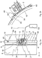
- Fig. 2a An arrangement is shown as is possible when using the orbital welding device 1 according to the invention.
- a guide band 6 is arranged on the first tube 8 and / or the second tube 10, the guide band 6 making it possible to couple an orbital welding device 1.
- the orbital welding device 1 preferably has at least one drive device 16, the drive device 16 interacting with the guide belt 6 to move the orbital welding device 1 with respect to the guide belt 6.
- the drive device 16 can be arranged in different positions and thus positions and orientations relative to a frame part 2 of the orbital welding device 1.
- the pipes 8, 10 are preferably connected by treating a connecting area 9 with a connecting device 14 of the connecting device 1.
- the letter M denotes a line which in the axial direction A represents the center or the axial center of the guide belt 6.
- the guide band 6 On one side or on both sides of the axial center M, the guide band 6 has a negative structure 47.
- the negative structure 47 is preferably essentially and particularly preferably exactly negative to the rotating shape of a drive wheel 38 of the drive device 16.
- the guide band 6 preferably has fixing means 60, in particular bores Apply spacer 62 on. Furthermore, the guide band 6 preferably has a tensioning device 54 for adapting the radius of the guide band 6. The guide band 6 can thus be pressed against the pipe 10 by means of the tensioning device 54 or pressed against the spacing means 62 arranged between the pipe 10 and the guide band 6.
- reference symbol 130 denotes a source, in particular a source for operating resources. However, it is also conceivable here that two, three, four, five or more sources are provided and the individual sources 130 are connected to the welding device 1 according to the invention via individual or common supply lines.
- a source 130 can e.g. serve to provide electricity, gas, a liquid and / or signals and / or other substances.
- Fig. 2b are some of the in Fig. 2a Components shown shown in sections in a side view. It can be seen from this illustration that the drive wheel 38 of the drive device 16 is in engagement with the guide belt 6 on the axially extending surface of the guide belt 6. Furthermore, reference numeral 40 identifies the end face of the guide band 6.
- a plurality of spacing means 62 are also arranged between the second tube 10 and the guide band 6.
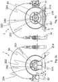
- Fig. 3a a side view of a part of the orbital welding device 1 according to the invention is shown. It can be seen from this illustration that the coil 50 or the welding wire storage device 50 is held relative to the frame part 2 via a first holding device 200.
- the first holding device 200 forms a first bearing seat 214 which is designed to receive the axle device 202 and a fixing means 212 (cf. Figures 7a-7b ) includes.
- the holding device 200, 201 is preferably designed such that it specifies a defined position for the coil 50.
- the orientation of the coil 50 in the defined position is in particular carried out by one or two positioning element (s) 266 or a positioning / alignment aid, which is preferably designed or arranged in the form of a pin or strut on the first holding device 200 and / or on the second holding device 201 / are caused.
- Two positioning elements 266 are preferably arranged or spaced from one another in such a way that the coil 50 comes to rest on them in a defined manner, as a result of which the through opening 256 is arranged or aligned between the bearing seats 214, 215 in a manner suitable for coupling with the axis device 202.
- the coil 50 can preferably fall into the holding device 200, 201 and is automatically transferred to a defined position.
- the reference numeral 92 designates a drive device, in particular for effecting a wire feed.
- the coil 50 has an upper cable receiving portion 264 (cf. Fig. 4 ) and a lower holding structure 253 which is at least partially formed towards an axis of rotation.
- the holding structure 253 preferably has one or more connecting points 254 for connecting to at least one connecting element or pin 250 formed on the axis device 202.
- the orbital welding device 1 is also shown in a side view, the view shown here showing the device from the opposite direction in FIG Fig. 3a direction of view shown.
- the axis device 202 is held on this side of the coil 50 in a bearing seat 215 which is held by a second holding device 201.
- the axis device 202 has an operating element 206 designed as a handle.
- an arm 248 or a cantilever or a projection is preferably arranged or formed on the axis device 202, which preferably extends in the radial direction.
- the arm 248 is preferably formed on an end cap 244 of the coil axis.
- the second bearing seat 215 and / or the second holding device 201 formed on the second holding device 201 has a recess 252 for receiving the arm 248.
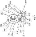
- a perspective view of a part of the orbital welding device 1 according to the invention is shown.
- the illustration shows the arrangement of the individual components during the disassembly or replacement of the coil 50
- a first holding device 200 is provided on the frame part 2, on which a first bearing seat 214 is arranged for receiving a first end of the axle device 202.
- a second holding device 201 is arranged on the frame part 2, which forms a second bearing seat 215 for receiving a second end of the axle device 202 spaced from the first end of the axle device 202.
- the coil 50 is preferably oriented such that the axis of rotation extending in the through opening 256, about which the coil 50 can be rotated, extends in a preferably essentially and particularly preferably exactly horizontal plane.
- the coil 50 is preferably a standing coil.
- the coil 50 is preferably inserted laterally and particularly preferably from above into the holding device 200, 201. The insertion of the coil 50 into the holding device 200, 201 is particularly preferably possible with one hand.
- the position or orientation of the coil 50 means that the wire preferably only has to be twisted about an axis, which results in fewer problems with arc stability and thus better welding quality.
- An axis device 202 is shown as an assembly of several elements or devices.
- the axle device 202 comprises an axle 203, a braking device 208 and an operating element 206
- Fig. 5 derive that the braking device 208 preferably a pressure plate 240 and / or a Compression spring 242, wherein the pressure plate 240 and / or the compression spring 242 are preferably arranged between a driver plate 238 and a coil holder 224.
- the driver plate 238 is preferably partially in the axial direction by a coil tube 236 superimposed, the coil tube 236 preferably also at least partially superimposed on a cover 234.
- the coil tube 236 is thus particularly preferably closed on the one hand by a cover 234 and on the other hand by a driver plate 238.
- Axle 203 and coil holder 224 are preferably joined by a counter flange 232 in a radial direction to cover 234.
- the counter flange 232 is preferably held in its position relative to the axis 203 by an adjusting ring 230.
- the axis 203 preferably has a coil lock or an end bearing 226.
- the end bearing 226 is particularly preferably held on the axis 203 by an axis-side coupling means 228, which is preferably designed as a dowel pin.
- the dowel pin 228 can be understood as a first axis-side fixing means 210 which is combined with a second fixing means 212 which is formed or arranged in the region of the first holding device 200 (cf. Figures 7a-7d ), for fixing or locking the position and / or the orientation of the axis device 202.
- the axis device 202 accordingly has a first fixing means 210 at one end, which is preferably designed as a dowel pin 228.
- the first fixing means 210 is followed by a counter flange 232, which in turn is in contact with a coil tube 236 via a cover 234.
- the coil tube 236 is further coupled to a driver plate 238, on which the arm 248 with the nose 250 is arranged.
- An end cap 244 axially adjoins the driver plate 238 toward a further end of the axis 203, which is axially at least partially superimposed by an operating element 206 coupled to the axis 203 by means of a dowel pin 246.
- the axle or axle device 202 is preferably, together with the braking device 208, through the coil holder 201 and the through opening 256 (cf. Fig. 4 ) the coil 50 pushed through and locked.
- the axis device 202 can be completely removable or can be held in an end position.
- the axis device 202 is closed and opened by means of the actuating device 206 with a rotation of 10 ° -350 °, and preferably of 10 ° -180 ° and particularly preferably of 10 ° -90 ° or of substantially or exactly approximately 30 °.
- the fixing device can e.g. be designed as a type of bayonet lock, the locking effect being achieved by the interaction of the first fixing means 210 and the second fixing means 212.
- FIG. 7a Various representations of the second fixing means 212 arranged or formed on the first bearing seat 214 on the first holding device 200 are shown.
- Fig. 7a it can be seen that the bearing seat 214, for example by means of several Screws, in particular by means of two, three, four or more screws 258 can be fixed on the first holding device 200.
- the second fixing device 212 which is designed to interact with the axis-side first fixing device 210, preferably has one or two depressions 260.
- the number of recesses 260 is preferably dependent on the number of dowel pins 228 which are formed on the axle device 202 as first fixing means 210, although it is additionally or alternatively conceivable that more recesses 260 are provided as dowel pins 228.
- each of the recesses 260 is followed by a fixing point 262, the axis device 202 being rotatable by means of the operating element 206 such that the dowel pins 228 of the axis device 202 can be converted into a positive and / or frictional connection with the second fixing means 212 .
Landscapes
- Engineering & Computer Science (AREA)
- Physics & Mathematics (AREA)
- Mechanical Engineering (AREA)
- Optics & Photonics (AREA)
- Plasma & Fusion (AREA)
- Butt Welding And Welding Of Specific Article (AREA)
- Wire Processing (AREA)
Description
- Die vorliegende Erfindung bezieht sich gemäß Anspruch 1 auf eine Orbitalschweißvorrichtung zum Verbinden von Rohren. Die Merkmale der Präambel des Anspruchs 1 sind beispielsweise in der Druckschrift
US 3 806 694 A offenbart. - Die vorliegende Erfindung liegt auf dem technischen Gebiet der Fügetechnik. Leitungen, insbesondere Leitungen zum Führen von Gasen, bestehen oftmals aus Rohren, insbesondere aus Metall, und werden je nach Anwendungsgebiet mittels Kleben, Löten oder Schweißen miteinander verbunden.
- Es werden insbesondere beim Onshore-Schweißen von Pipelines (Gas& Öl-Pipelines) Orbitalschweißsysteme (Bugs) genutzt, wobei das Schweißgerät auf einem Positionierband fährt, das um ein Rohr befestigt wird, und eine zwischen die einzelnen Rohre der Pipeline verbindende Schweißnaht mit einer oder mehreren Raupen nebeneinander oder übereinander einbringt.
- Die Druckschrift
WO2009122217A1 offenbart z.B. einen Schweißbug der über einen fest installierten Stirnradantrieb gegenüber einem Führungsband bewegt wird. Bei Schweißbugs, wie z.B. dem aus der DruckschriftWO2009122217A1 oder einem aus der DruckschriftEP 1100645 B1 bekannten Schweißbug, ist die Spule horizontal bzw. leicht geneigt auf dem Schweißbug angebracht. Dies bringt den Nachteil mit sich, dass der Draht auf dem Weg von der Spule zum Brenner um zwei Achsen verwunden werden muss, um die Schweißqualität zu gewährleisten, ist es jedoch wichtig, dass der Draht bei Ankunft an der Schweißstelle möglichst wenig vorgekrümmt ist, damit der zum Schweißen erforderliche Lichtbogen möglichst stabil aufrecht erhalten werden kann. - Die Druckschrift
US 5,676,857 offenbart ein System zum Verschweißen von Rohren, um eine lange, kontinuierliche Pipeline zu schaffen. Ein Schweißwagen bzw. ein Schweißbug ist an einer Führungsschiene, die sich um den Umfang des Rohres erstreckt, montiert. Der Schweißwagen ist mit einem Drahtvorschub, einem Motor, um den Drahtvorschub anzutreiben, und einem Antriebsmotor zum Bewegen des Bugs entlang der Führung ausgestattet. Die Geschwindigkeit des Bugs und des Drahtvorschubs ist variierbar, während der Bug kontinuierlich um das Rohr bewegt wird. Die erste Schweißnaht oder Wurzelschweißnaht wird gemäß dem Gegenstand derUS 5,676,857 von außerhalb des Rohres geschweißt. Der aus derUS 5,676,857 bekannte Bug wird dabei über einen fest installierten Stirnradantrieb angetrieben. Weiterhin weist der Bug einen Halterahmen zum Halten einer Spule zur Drahtaufnahme auf. Die Spule ist dabei gemäß dem Gegenstand derUS 5,676,857 mittels einer Schraubverbindung an dem Halterahmen angeschraubt. - Übliche Spulen, auf denen der Schweißdraht vorgehalten wird wiegen in der Regel um die 5kg und werden, wie bei der
US 5,676,857 , auf dem Gerät mitgefahren. Die Spulen bewirken aufgrund ihres Gewichts und ihrer Form, dass sie äußerst unhandlich sind und daher eine Montage der Spule an einem Bug, insbesondere in einem Gebrauchszustand, für einen einzelnen Arbeiter äußerst umständlich ist. Insgesamt erfordert der Spulentausch vergleichsweise viel Zeit und erfolgt ergonomisch ungünstig. Weitere Druckschriften, die Schweißeinrichtungen offenbaren sind z.B.US3806694A ,US5227601A ,US2009/236462A1 ,US1615149A . - Es ist somit Aufgabe der vorliegenden Erfindung eine Lösung, insbesondere in Form einer Orbitalschweißvorrichtung, bereitzustellen, mittels welcher ein Austausch der Spule erleichtert, insbesondere beschleunigt und vereinfacht, wird. Weiterhin ist es eine Aufgabe der vorliegenden Erfindung eine Orbitalschweißvorrichtung so auszugestalten, dass eine hohe Schweißqualität gewährleistet wird.
- Die zuvor genannte Aufgabe wird durch eine Orbitalschweißvorrichtung gemäß Anspruch 1, insbesondere zum Onshore-Schweißen, gelöst. Die Orbitalschweißvorrichtung weist dabei mindestens ein Rahmenteil zum Anordnen einer oder mehrerer Funktionseinrichtungen, einen Kopplungsbereich zum Ankoppeln an ein Führungsband, wobei in einem Betriebszustand das Führungsband bevorzugt an einem Rohr befestigt ist, das Führungsband das Rohr in Umfangsrichtung umschließt und sich das Führungsband in axialer Richtung erstreckt, wobei es dabei das Rohr abschnittsweise überlagert, eine Anschlusseinrichtung zum Anschließen von mindestens einer Zuführleitung, eine mit der Anschlusseinrichtung über eine Zuführleitung verbundener Schweißkopf, mindestens eine Antriebseinrichtung, wobei die Antriebseinrichtung zum Bewegen der Schweißvorrichtung gegenüber dem Führungsband mit dem Führungsband zusammenwirkt, und eine am Rahmenteil angeordnete Halteeinrichtung zum Aufnehmen einer Achseneinrichtung umfasst. Die Halteeinrichtung nimmt dabei die Achseneinrichtung bevorzugt derart auf, dass sich die Längsachse der Achseneinrichtung im Wesentlichen horizontal erstreckt, wobei die Achseneinrichtung zum Aufnehmen einer Schweißdrahtbevorratungseinrichtung ausgebildet ist, wobei die Achseneinrichtung die Schweißdrahtbevorratungseinrichtung derart aufnimmt, dass sie zumindest zeitweise gegenüber dem Rahmenteil drehbar ist, wobei die Achseneinrichtung ein Bedienelement, insbesondere einen Griff, auf, wobei die Achseneinrichtung zumindest zeitweise mittels des Bedienelements bewegbar ist, und wobei die Achseneinrichtung mittels einer Fixiereinrichtung gegenüber dem Rahmenteil in mindestens einer Stellung arretierbar ist.
- Als Funktionseinrichtung kann hierbei z.B. eine Antriebseinrichtung, eine Anschlusseinrichtung, eine Steuerungseinrichtung, eine einen Kopplungsbereich definierende Kopplungseinrichtung, etc. angesehen werden.
- Eine sich im Wesentlichen horizontal erstreckende Achse ist in einem mit der Halteeinrichtung gekoppelten Zustand in einem Winkel von z.B. weniger als 30° und weiter bevorzugt in einem Winkel von weniger als 15° und besonders bevorzugt in einem Winkel von weniger als 5° gegenüber der Horizontalen geneigt.
- Diese Lösung ist vorteilhaft, da das Einlegen und/oder Austauschen der Spule ergonomischer gestalten ist, wodurch z.B. auch ein verbessertes einhändiges Einlegen und/oder Austauschen ermöglicht wird. Aufgrund der bevorzugt horizontal ausgerichteten Rotationsachse der Schweißdrahtbevorratungseinrichtung ist ferner die Möglichkeit geboten, dass der Draht auf dem Weg zum Brenner weniger Verwindung erfährt und somit die Schweißqualität verbessert wird. Weiterhin bietet die vorliegende Erfindung ebenfalls aufgrund der vorteilhaften Ausgestaltung der Halteeinrichtung die Möglichkeit eine Leichtbaugestaltung zu realisieren.
- Gemäß einer bevorzugten Ausführungsform der vorliegenden Erfindung ist die Halteeinrichtung derart gestaltet, dass sie die Achseneinrichtung auf beiden Seiten der Schweißdrahtbevorratungseinrichtung in definierten Lagersitzen aufnimmt, wenn die Schweißdrahtbevorratungseinrichtung mit der Schweißvorrichtung gekoppelt ist.
- Diese Ausführungsform ist vorteilhaft, da durch die mehreren Lagersitze die Schweißdrahtbevorratungseinrichtung äußerst präzise und stabil gehalten wird. Die Ausrichtung der Schweißdrahtbevorratungseinrichtung ist somit immer sichergestellt, wodurch eine äußerst gleichförmige bzw. homogene Zuführung des auf der Schweißdrahtbevorratungseinrichtung vorgehaltenen länglichen Materials, insbesondere des Schweißdrahtes, zum Schweißkopf bewirkbar ist.
- Der Rahmenteil ist gemäß einer weiteren bevorzugten Ausführungsform der vorliegenden Ausführungsform derart gestaltet oder derart mit Positioniermitteln versehen, dass eine Schweißdrahtbevorratungseinrichtung in einem entkoppelten Zustand derart gegenüber der Halteeinrichtung ausgerichtet bzw. positioniert ist, dass durch die Einbringung der Achseneinrichtung eine Überführung der Schweißdrahtbevorratungseinrichtung aus dem entkoppelten Zustand in einen gekoppelten Zustand erfolgt. Diese Ausführungsform ist vorteilhaft, da die Montage der Schweißdrahtbevorratungseinrichtung für eine Person deutlich erleichtert ist. Die Person braucht die schwere Schweißdrahtbevorratungseinrichtung nicht frei zu halten, wozu sie stets zwei Hände benötigen würde, sondern kann zunächst die Schweißdrahtbevorratungseinrichtung in eine Ausgangsposition bringen und dann durch das Bewegen der Achseneinrichtung die Schweißdrahtbevorratungseinrichtung in einen gekoppelten Zustand überführen. Die Bewegung der Achseinrichtung und somit die Montage der Schweißdrahtbevorratungseinrichtung kann durch diese Lösung besonders bevorzugt einhändig durchgeführt werden, was eine enorme Vereinfachung, Zeitersparnis, Kostenersparnis und Risikoreduzierung bewirkt.
- Die Fixiereinrichtung umfasst gemäß der vorliegenden Erfindung ein erstes achsenseitiges Fixiermittel und ein zweites Fixiermittel, wobei das zweite Fixiermittel an einem Lagersitz oder im Bereich eines Lagersitzes der Halteeinrichtung angeordnet oder ausgebildet ist, wobei das erste Fixiermittel und das zweite Fixiermittel in Abhängigkeit einer mittels des Bedienelements bewirkbaren Rotation der Achseneinrichtung um ihre Längsachse und somit einer Rotation des ersten Fixiermittels um die Längsachse der Achseneinrichtung eine Arretierung der Achseneinrichtung gegenüber der Halteeinrichtung bewirkt. Diese Ausführungsform ist vorteilhaft, da keine aufwendigen Fixierschritte, insbesondere kein zeitaufwendiges Verschrauben, durchgeführt werden müssen und die Fixierung der Schweißdrahtbevorratungseinrichtung äußerst einfach vornehmbar ist. Die Fixierung der Schweißdrahtbevorratungseinrichtung kann somit ebenfalls von fachfremden Personen unmittelbar, sicher und schnell bewirkt werden.
- Gemäß der vorliegenden Erfindung ist eine Bremseinrichtung zum Verlangsamen der Rotationsbewegung der Schweißdrahtbevorratungseinrichtung vorgesehen, wobei die Bremseinrichtung zumindest ein unkontrolliertes Abwickeln eines auf der Schweißdrahtbevorratungseinrichtung vorgehaltenen Schweißdrahtes verhindert. Diese Ausführungsform ist vorteilhaft, da das unerwünschte Abrollen einer Schweißdrahtbevorratungseinrichtung verhindert wird, das sonst dazu führen würde, dass ein Verklemmen des Drahtes im System erfolgt oder dass die Schweißdrahtbevorratungseinrichtung nicht wieder verwendbar ist, wodurch Mehrkosten für den Ersatz des auf der Schweißdrahtbevorratungseinrichtung vorgehaltenen Drahtes entstehen oder die Qualität der Wicklung des Drahtes auf der Schweißdrahtbevorratungseinrichtung reduziert ist, woraus eine Beeinträchtigung des Schweißergebnisses resultieren kann. Besonders bevorzugt kann die Fixierung der Schweißdrahtbevorratungseinrichtung einhändig erfolgen.
- Die Bremseinrichtung ist gemäß einer weiteren bevorzugten Ausführungsform der vorliegenden Erfindung derart als Teil der Achseneinrichtung ausgebildet, dass eine Bewegung der Achseneinrichtung infolge einer Bedienung des Bedienelements bevorzugt unmittelbar eine Bewegung, insbesondere eine Verschiebung in axialer Richtung, der Bremseinrichtung bewirkt. Die Bremseinrichtung ist als Teil der Achseneinrichtung ausgebildet, wodurch eine sehr platzsparende und leichte Ausgestaltung geschaffen ist. Weiterhin weist die Bremseinrichtung gemäß einer weiteren bevorzugten Ausführungsform ein Kopplungselement zum formschlüssigen Koppeln mit einem dazu zumindest teilweise negativ ausgebildeten Verbindungselement der Schweißdrahtbevorratungseinrichtung auf. Diese Ausführungsform ist vorteilhaft, da das Kopplungselement bevorzugt derart ausgestaltet ist, dass es beim Anbringen der Schweißdrahtbevorratungseinrichtung, d.h. zeitgleich zum Verfahren der Achseneinrichtung, an der Halteeinrichtung bevorzugt selbsttätig in Eingriff kommt und somit selbsttätig eine Kopplung zwischen der Bremse und der Schweißdrahtbevorratungseinrichtung erzeugt.
- Gemäß der vorliegenden Erfindung stellt die Achseneinrichtung eine Baugruppe dar, die eine Achse, an der ein erster Achsenlagersitz und ein zweiter Achsenlagersitz zur Positionierung in oder an der Halteeinrichtung ausgebildet sind, ein erstes Fixiermittel zum Zusammenwirken mit einem im Bereich der Halteeinrichtung ausgebildeten zweiten Fixiermittel, eine Bremseinrichtung zum Reduzieren der Rotationsgeschwindigkeit der Schweißdrahtbevorratungseinrichtung und ein Bedienelement zum manuellen Positionieren sowie Rotieren der Achseneinrichtung aufweist. Diese Ausführungsform ist vorteilhaft, da mittels eines Bewegungsablaufs, wie z.B. Einführen der Achseneinrichtung in die Lagerstellen zum Positionieren der Schweißdrahtbevorratungseinrichtung eine Fixierung und/oder Positionierung der Schweißdrahtbevorratungseinrichtung und eine Kopplung mit der Bremse bewirkbar ist. Diese Funktionsintegration ermöglicht einen sehr schnellen und einfachen Austausch von Schweißdrahtbevorratungseinrichtungen.
- Die Bremseinrichtung ist gemäß einer weiteren bevorzugten Ausführungsform der vorliegenden Erfindung derart an dem Rahmenteil oder der Halterung angeordnet, dass infolge des Ankoppelns der Schweißdrahtbevorratungseinrichtung eine Wirkverbindung zwischen der Schweißdrahtbevorratungseinrichtung und der Bremseinrichtung erzeugbar ist. Diese Ausführungsform ist vorteilhaft, da unabhängig von der Stellung bzw. Position der Achseneinrichtung die Bremseinrichtung zugänglich und somit überwachbar und/oder konfigurierbar ist.
- Einzelne oder alle Darstellungen der im Nachfolgenden beschriebenen Figuren sind bevorzugt als Konstruktionszeichnungen anzusehen, d.h. die sich aus der bzw. den Figuren ergebenden Abmessungen, Proportionen, Funktionszusammenhänge und/oder Anordnungen entsprechen bevorzugt genau oder bevorzugt im Wesentlichen denen der erfindungsgemäßen Vorrichtung bzw. des erfindungsgemäßen Produkts.
- Weitere Vorteile, Ziele und Eigenschaften vorliegender Erfindung werden anhand nachfolgender Beschreibung anliegender Zeichnungen erläutert, in welchen beispielhaft erfindungsgemäße Verbindungsvorrichtungen dargestellt sind. Elemente der erfindungsgemäßen Vorrichtungen, welche in den Figuren wenigsten im Wesentlichen hinsichtlich ihrer Funktion übereinstimmen, können hierbei mit gleichen Bezugszeichen gekennzeichnet sein, wobei diese Bauteile bzw. Elemente nicht in allen Figuren beziffert oder erläutert sein müssen. Nachfolgend wird die Erfindung rein beispielhaft anhand der beigefügten Figuren beschrieben.
- Darin zeigen:
- Fig. 1a
- eine erste Seitenansicht der erfindungsgemäßen Schweißvorrichtung aus einer orthogonal zur axialen Richtung stehenden Richtung;
- Fig. 1b
- eine zweite Seitenansicht aus einer der Richtung der ersten Seitenansicht entgegenstehenden Richtung;
- Fig. 2a
- eine Draufsicht auf eine erfindungsgemäße Schweißvorrichtung in einer Gebrauchssituation;
- Fig. 2b
- eine teilweise Darstellung der in
Fig. 2a gezeigten Anordnung in einer Seitenansicht; - Fig. 3a
- eine Seitenansicht der Schweißdrahtbevorratungseinrichtung in einem mit der Halteeinrichtung gekoppelten Zustand;
- Fig. 3b
- eine weitere Seitenansicht der Schweißdrahtbevorratungseinrichtung in einem mit der Halteeinrichtung gekoppelten Zustand aus einer gegenüber
Fig. 3a gegensätzlichen Richtung; - Fig. 4
- eine perspektivische Darstellung einer Schweißdrahtbevorratungseinrichtung, einer Achseneinrichtung und einer Halteeinrichtung in einem nicht gekoppelten Zustand;
- Fig. 5
- eine Schnittdarstellung einer Achseneinrichtung;
- Fig. 6a/b
- perspektivische Ansichten der Achseneinrichtung;
- Fig. 7a-d
- verschiedene Ansichten des ersten Lagersitzes der Halteeinrichtung.
- In
Fig. 1a ist eine erste Seitenansicht einer erfindungsgemäßen Orbitaischweißvorrichtung 1 gezeigt. Die Orbitalschweißvorrichtung 1 weist dabei ein Rahmenteil 2 zum Anordnen einer oder mehrerer Funktionseinrichtungen auf. Weiterhin umfasst die Orbitalschweißvorrichtung 1 einen Kopplungsbereich 4 zum Ankoppeln an ein Führungsband 6. Der Kopplungsbereich 4 ist bevorzugt mit Führungselementen bzw. Kopplungselementen 5 ausgestattet, die bevorzugt zum Erzeugen eines Formschlusses zur Reduzierung der Bewegungsfreiheitsgrade der Orbitalschweißvorrichtung 1 vorgesehen sind. Die Orbitalschweißvorrichtung 1 ist, wenn sie mit dem Führungsband 6 gekoppelt ist, bevorzugt lediglich in der durch das Führungsband 6 ausgebildeten Umfangsrichtung U um ein Rohr 10 (vgl,Fig. 7a ) herumführbar. Die Kopplungselemente 5 reduzieren bzw. begrenzen bzw. verhindern bevorzugt im Wesentlichen und besonders bevorzugt vollständig eine Relativbewegung der Schweißvorrichtung 1 gegenüber dem Führungsband 6 in axialer Richtung A und/oder in radialer Richtung. Somit ist das Führungsband 6 in einem Betriebszustand bevorzugt an dem Rohr 10 befestigt bzw. das Führungsband 6 umschließt das Rohr 10 in Umfangsrichtung U und erstreckt sich in axialer Richtung A des Rohres 10, wobei es dabei das Rohr 10 abschnittsweise überlagert. Das Führungsband 6 wird dabei bevorzugt an das Rohr 10 lösbar angekoppelt, insbesondere angepresst, angeschraubt und/oder angeheftet. - Weiterhin ist in
Fig. 1a eine Anschlusseinrichtung 11 zum Anschließen von mindestens einer Zuführleitung 12 gezeigt. Die Anschlusseinrichtung 11 dient dabei bevorzugt zur Anbindung einer oder mehrerer Betriebsmittelquellen an die Schweißvorrichtung 1. Als Betriebsmittelquelle kann hierbei neben anderem eine Gasquelle und/oder eine Signalquelle und/oder eine Stromquelle angesehen werden. Die Anschlusseinrichtung 11 weist bevorzugt einen Gasanschluss zur Anbindung einer Versorgungsleitung 13 (vgl.Fig. 2a ) auf. Das der Anschlusseinrichtung 11 zugeführte Gas ist über eine Zuführleitung 12 einem Schweißkopf 14 zum Ermöglichen eines Schweißprozesses zuführbar, wobei die Anschlusseinrichtung 11 über die Zuführleitung 12 mit dem Schweißkopf 14 funktional verbunden ist. Ferner ist in die Drahtvorschubeinrichtung 92 ein kabel- oder bandartiges Endlosmaterial, insbesondere ein Schweißdraht, einbringbar, das auf einer an der Orbitalschweißvorrichtung 1 angebrachten Spule 50 vorhaltbar ist. Das Endlosmaterial ist über eine weitere an der Drahtvorschubeinrichtung 92 anbringbare Leitung (nicht gezeigt) ebenfalls dem Schweißkopf 14 zuführbar. - Das Bezugszeichen 64 kennzeichnet ferner ein Zustellmittel, mittels dem der Schweißkopf 14 zumindest in der vertikalen und/oder horizontalen Richtung verfahrbar ist. Bevorzugt ist über das Zustellmittel 64 eine bevorzugte Stellung des Schweißkopfes 14 einstellbar und arretierbar. Es ist weiterhin denkbar, dass das Zustellmittel 64 einen, zwei, drei oder mehrere Motoren zum Bewirken der einzelnen Verfahrbewegungen des Schweißkopfes 14 aufweist. Bevorzugt weist das Zustellmittel 64 zwei Linearmotoren 66, 68 (vgl.
Fig. 2a ) zum Bewirken der Verfahrbewegungen auf, wobei ein erster Linearmotor 66 im Wesentlichen oder genau in vertikaler Richtung orientiert bzw. ausgerichtet ist und ein zweiter Linearmotor 68 im Wesentlichen oder genau in horizontaler Richtung orientiert bzw. ausgerichtet ist. - In
Fig. 1b ist eine gegenüber der inFig. 1 a gezeigten ersten Seitenansicht weitere zweite Seitenansicht dargestellt. Die erste Seitenansicht und die zweite Seitenansicht sind dabei Ansichten aus einander gegenüberliegenden Richtungen. Die Spule 50 ist gemäß der inFig. 1b gezeigten Darstellung über ein Aufnahmemittel 52, das bevorzugt eine herausnehmbare Achse darstellt, die mit einer Bremse gekoppelt ist, am Rahmen bzw. Rahmenteil 2 abgestützt bzw. gegenüber dem Rahmen 2 ortsfest angeordnet. - Weiterhin lässt sich der
Fig. 1b ein Koordinatensystem entnehmen, das eine erste Richtung X, eine zweite Richtung Y und eine dritte Richtung Z definiert. Die erste Richtung X entspricht hierbei bevorzugt der vertikalen Richtung, die zweite Richtung Y entspricht hierbei bevorzugt der Breitenrichtung und die dritte Richtung entspricht bevorzugt einer Tiefenrichtung der Vorrichtung. In Y-Richtung erstreckt sich bevorzugt auch stets die axiale Richtung A (vgl.Fig. 1a ). Weiterhin spannen die Richtungen Y und Z bevorzugt eine horizontale Ebene auf. InFig. 2a ist eine Anordnung gezeigt, wie sie beim Einsatz der erfindungsgemäßen Orbitalschweißvorrichtung 1 möglich ist. Beim Verbinden von Rohren 8, 10, insbesondere gasführenden Rohren, wird zunächst ein erstes Rohr 8 bereitgestellt, dann wird ein zweites Rohr 10 bereitgestellt, das mit dem ersten Rohr 8 verbunden werden soll. Weiterhin wird ein Führungsband 6 an dem ersten Rohr 8 und/oder dem zweiten Rohr 10 angeordnet, wobei das Führungsband 6 die Ankopplung einer Orbitalschweißvorrichtung 1 ermöglicht. Die Orbitaischweißvorrichtung 1 weist dabei bevorzugt mindestens eine Antriebseinrichtung 16 auf, wobei die Antriebseinrichtung 16 zum Bewegen der Orbitalschweißvorrichtung 1 gegenüber dem Führungsband 6 mit dem Führungsband 6 zusammenwirkt. Die Antriebseinrichtung 16 ist gegenüber einem Rahmenteil 2 der Orbitalschweißvorrichtung 1 in unterschiedlichen Stellungen und somit Positionen und Orientierungen anordenbar. Beim Bewegen der Orbitalschweißvorrichtung 1 in Umfangsrichtung U der Rohre 8, 10 entlang dem Führungsband 6 erfolgt bevorzugt ein Verbinden der Rohre 8, 10 durch eine Behandlung eines Verbindungsbereichs 9 mit einer Verbindungseinrichtung 14 der Verbindungsvorrichtung 1. Der Buchstabe M kennzeichnet eine Linie, welche in der axialen Richtung A die Mitte bzw. die axiale Mitte des Führungsbandes 6 darstellt. Einerseits oder beiderseits der axialen Mitte M weist das Führungsband 6 eine Negativstruktur 47 auf. Die Negativstruktur 47 ist dabei bevorzugt im Wesentlichen und besonders bevorzugt genau negativ zur umlaufenden Form eines Antriebsrads 38 der Antriebseinrichtung 16 ausgebildet. - Das Führungsband 6 weist bevorzugt Fixiermittel 60, insbesondere Bohrungen, zur Anbringung von Beabstandungsmittel 62 auf. Weiterhin weist das Führungsband 6 bevorzugt eine Spanneinrichtung 54 zur Anpassung des Radius des Führungsbandes 6 auf. Das Führungsband 6 ist somit mittels der Spanneinrichtung 54 an das Rohr 10 anpressbar bzw. an die zwischen dem Rohr 10 und dem Führungsband 6 angeordneten Beabstandungsmittel 62 anpressbar.
- Ferner kennzeichnet das Bezugszeichen 130 eine Quelle, insbesondere eine Quelle für Betriebsmittel. Es ist hierbei jedoch ebenfalls denkbar, dass zwei, drei, vier, fünf, oder mehrere Quellen vorgesehen sind und die einzelnen Quellen 130 über einzelne oder gemeinsame Versorgungsleitungen mit der erfindungsgemäßen Schweißvorrichtung 1 verbunden sind. Eine Quelle 130 kann dabei z.B. zur Bereitstellung von Strom, Gas, einer Flüssigkeit und/oder Signalen und/oder anderen Stoffen dienen.
- In
Fig. 2b sind einzelne der inFig. 2a gezeigten Komponenten ausschnittsweise in einer Seitenansicht gezeigt. Es ist dieser Darstellung zu entnehmen, dass das Antriebsrad 38 der Antriebseinrichtung 16 auf der sich axial erstreckenden Oberfläche des Führungsbandes 6 mit dem Führungsband 6 in Eingriff befindet. Weiterhin kennzeichnet das Bezugszeichen 40 die Stirnseite des Führungsbandes 6. - Zwischen dem zweiten Rohr 10 und dem Führungsband 6 sind zudem mehrere Beabstandungsmittel 62 angeordnet.
- In
Fig. 3a ist eine Seitenansicht eines Teils der erfindungsgemäßen Orbitaischweißvorrichtung 1 gezeigt. Dieser Darstellung lässt sich entnehmen, dass die Spule 50 bzw. die Schweißdrahtbevorratungseinrichtung 50 über eine erste Halteeinrichtung 200 gegenüber dem Rahmenteil 2 gehalten wird. Die erste Halteeinrichtung 200 bildet dabei einen ersten Lagersitz 214 aus, der zur Aufnahme der Achseneinrichtung 202 ausgestaltet ist und ein Fixiermittel 212 (vgl.Fig. 7a-7b ) umfasst. Die Halteeinrichtung 200, 201 ist bevorzugt derart gestaltet, dass sie für die Spule 50 eine definierte Position vorgibt. Die Ausrichtung der Spule 50 in der definierten Position wird insbesondere durch ein oder zwei Positionierelement/e 266 bzw. eine Positionier-/Ausrichthilfe, die bevorzugt zapfenförmig oder strebenförmig an der ersten Halteeinrichtung 200 und/oder an der zweiten Halteeinrichtung 201 ausgebildet bzw. angeordnet ist/sind, bewirkt. Bevorzugt sind zwei Positionierelemente 266 derart zueinander angeordnet bzw. beabstandet, dass die Spule 50 definiert daran zum Liegen kommt, wodurch die Durchgangsöffnung 256 in zum Koppeln mit der Achseneinrichtung 202 geeigneter Weise zwischen den Lagersitzen 214, 215 angeordnet bzw. ausgerichtet wird. Die Spule 50 kann dabei bevorzugt in die Halteeinrichtung 200, 201 fallen und wird selbsttätig in eine definierte Position überführt. Weiterhin kennzeichnet das Bezugszeichen 92 eine Antriebseinrichtung, insbesondere zum Bewirken eines Drahtvorschubs. Die Spule 50 weist zum einen einen oberen Kabelaufnahmeanteil 264 (vgl.Fig. 4 ) und eine untere zu einer Drehachse hin zumindest teilweise ausgebildete Haltestruktur 253 auf. Die Haltestruktur 253 weist bevorzugt eine oder mehrere Verbindungsstellen 254 zum Verbinden mit mindestens einem an der Achseneinrichtung 202 ausgebildeten Verbindungselement bzw. Zapfen 250 auf. - In
Fig. 3b ist die erfindungsgemäße Orbitalschweißvorrichtung 1 ebenfalls in einer Seitenansicht dargestellt, wobei die hier dargestellte Ansicht die Vorrichtung aus der entgegen der inFig. 3a gezeigten Blickrichtung zeigt. Es lässt sich dieser Darstellung entnehmen, dass die Achseneinrichtung 202 diesseits der Spule 50 in einem Lagersitz 215 gehalten wird, der von einer zweiten Halteeinrichtung 201 gehalten wird. Die Achseneinrichtung 202 weist gemäß dieser Darstellung ein als Griff ausgebildetes Bedienelement 206 auf. Weiterhin ist an der Achseneinrichtung 202 bevorzugt ein Arm 248 bzw. ein Ausleger bzw. ein Vorsprung angeordnet oder ausgebildet, der sich bevorzugt in radialer Richtung erstreckt. Der Arm 248 ist bevorzugt an einer Endkappe 244 der Spulenachse ausgebildet. Weiterhin weist der an der zweiten Halteeinrichtung 201 ausgebildete zweite Lagersitz 215 und/oder die zweite Halteeinrichtung 201 eine Ausnehmung 252 zum Aufnehmen des Arms 248 auf. - In
Fig. 4 ist eine perspektivische Darstellung eines Teil des erfindungsgemäßen Orbitalschweißvorrichtung 1 gezeigt. Die Darstellung zeigt hierbei die Anordnung der einzelnen Komponenten bei der Demontage bzw. einem Austausch der Spule 50. Es ist hierbei derFig. 4 zu entnehmen, dass an dem Rahmenteil 2 eine ersten Halteeinrichtung 200 vorgesehen ist, an der ein erster Lagersitz 214 zum Aufnehmen eines ersten Endes der Achseneinrichtung 202 angeordnet ist. Weiterhin ist gezeigt, dass eine zweite Halteeinrichtung 201 an dem Rahmenteil 2 angeordnet ist, die einen zweiten Lagersitz 215 zum Aufnehmen eines von dem ersten Ende der Achseneinrichtung 202 beabstandeten zweiten Ende der Achseneinrichtung 202 ausbildet. Die Spule 50 ist in dem Einbauzustand bevorzugt derart ausgerichtet, dass die sich in der Durchgangsöffnung 256 erstreckende Rotationsachse, um welche die Spule 50 rotierbar ist, in einer bevorzugt im Wesentlichen und besonders bevorzugt genau horizontalen Ebene erstreckt. Es handelt sich bei der Spule 50 bevorzugt um eine stehende Spule. Die Spule 50 wird dabei bevorzugt seitlich und besonders bevorzugt von oben in die Halteeinrichtung 200, 201 eingesetzt. Das Einsetzen der Spule 50 in die Halteeinrichtung 200, 201 ist dabei besonders bevorzugt einhändig möglich. - Weiterhin muss durch die Lage bzw. Ausrichtung der Spule 50 der Draht bevorzugt nur um eine Achse verwunden werden, wodurch weniger Probleme bei der Lichtbogenstabilität und somit eine bessere Schweißqualität resultiert.
- In
Fig. 5 ist eine Achseneinrichtung 202 als Baugruppe aus mehreren Elementen bzw. Einrichtungen dargestellt. Die Achseneinrichtung 202 umfasst eine Achse 203, eine Bremseinrichtung 208 und ein Bedienelement 206. Weiterhin lässt sich derFig. 5 entnehmen, dass die Bremseinrichtung 208 bevorzugt eine Druckscheibe 240 und/oder eine Druckfeder 242 aufweist, wobei die Druckscheibe 240 und/oder die Druckfeder 242 bevorzugt zwischen einer Mitnehmerplatte 238 und einem Spulenhalter 224 angeordnet sind. Die Mitnehmerplatte 238 wird bevorzugt teilweise in axialer Richtung von einem Spulenrohr 236 überlagert, wobei das Spulenrohr 236 bevorzugt ebenfalls zumindest teilweise einen Deckel 234 überlagert. Das Spulenrohr 236 wird somit besonders bevorzugt einerseits durch einen Deckel 234 und andererseits durch eine Mitnehmerplatte 238 abgeschlossen. An den Deckel 234 schließt sich bevorzugt in radialer Richtung die Achse 203 und den Spulenhalter 224 überlagernd ein Gegenflansch 232 an. Der Gegenflansch 232 wird bevorzugt durch einen Stellring 230 in seiner Position relativ zur Achse 203 gehalten. Am vom Bedienelement 206 beabstandeten weiteren Ende der Achseneinrichtung 202 weist die Achse 203 bevorzugt eine Spulenverriegelung bzw. ein Endlager 226 auf. Das Endlager 226 wird dabei besonders bevorzugt durch ein achsenseitiges Kopplungsmittel 228, das bevorzugt als Passstift ausgeführt ist, an der Achse 203 gehalten. Es ist hierbei jedoch ebenfalls denkbar, dass das Endlager 226 unlösbar mit der Achse 203 gekoppelt ist. Der Passstift 228 kann als erstes achsenseitiges Fixiermittel 210 verstanden werden, das mit einem zweiten Fixiermittel 212, das im Bereich der ersten Halteeinrichtung 200 ausgebildet bzw. angeordnet ist (vgl.Fig. 7a-7d ), zum Fixieren bzw. Arretieren der Position und/oder der Ausrichtung der Achseneinrichtung 202 dient. - In den
Figuren 6a und 6b sind zwei perspektivische Darstellungen der Achseneinrichtung 202 gezeigt. Die Achseneinrichtung 202 weist demnach an einem Ende ein erstes Fixiermittel 210, das bevorzugt als Passstift 228 ausgebildet ist, auf. In axialer Richtung schließt sich an das erste Fixiermittel 210 ein Gegenflansch 232 an, der wiederum über einen Deckel 234 mit einem Spulenrohr 236 in Kontakt steht. Das Spulenrohr 236 ist ferner mit einer Mitnehmerplatte 238 gekoppelt, an welcher der Arm 248 mit der Nase 250 angeordnet ist. Axial schließt sich an der Mitnehmerplatte 238 zu einem weiteren Ende der Achse 203 hin eine Endkappe 244 an, die von einem mittels einem Spannstift 246 an die Achse 203 angekoppelten Bedienelement 206 axial zumindest teilweise überlagert wird. - Die Achse bzw. Achseneinrichtung 202 wird bevorzugt samt Bremseinrichtung 208 durch die Spulenhalterung 201 und die Durchgangsöffnung 256 (vgl.
Fig. 4 ) der Spule 50 hindurch geschoben und verriegelt. Die Achseneinrichtung 202 kann dabei komplett entnehmbar sein oder in einer Endposition gehalten werden. - Die Achseneinrichtung 202 wird mittels der Betätigungseinrichtung 206 mit einer Drehung von 10°-350°, und bevorzugt von 10°-180° und besonders bevorzugt von 10°-90° bzw. von im Wesentlichen oder genau ca. 30° verschlossen und geöffnet. Die Fixiereinrichtung kann hierbei z.B. als eine Art Bajonettverschluss ausgebildet sein, wobei durch das Zusammenwirken des ersten Fixiermittels 210 und des zweite Fixiermittels 212 die Verschlusswirkung erzielt wird.
- In den
Figuren 7a-7d sind verschiedene Darstellungen des an dem ersten Lagersitz 214 an der ersten Halteeinrichtung 200 angeordneten bzw. ausgebildeten zweiten Fixiermittels 212 gezeigt.Fig. 7a lässt sich entnehmen, dass der Lagersitz 214 z.B. mittels mehrerer Schrauben, insbesondere mittels zwei, drei, vier oder mehr Schrauben 258 an der ersten Halteeinrichtung 200 fixierbar ist. Die zweite Fixiereinrichtung 212, die zum Zusammenwirken mit der achsenseitigen ersten Fixiereinrichtung 210 ausgebildet ist, weist bevorzugt eine oder zwei Vertiefungen 260 auf. Die Anzahl der Vertiefungen 260 ist dabei bevorzugt von der Anzahl an Passstiften 228 abhängig, die an der Achseneinrichtung 202 als erste Fixiermittel 210 ausgebildet sind, wobei jedoch zusätzlich oder alternativ denkbar ist, dass mehr Vertiefungen 260 als Passstifte 228 vorgesehen sind. Weiterhin lässt sich derFig. 7b entnehmen, dass sich an die Vertiefung/en 260 je eine Fixierstelle 262 anschließt, wobei die Achseneinrichtung 202 mittels dem Bedienelement 206 derart rotierbar ist, dass die Passstifte 228 der Achseneinrichtung 202 in eine formschlüssige und/oder reibschlüssige Verbindung mit dem zweiten Fixiermittel 212 überführbar sind. -
- 1
- Orbitalschweißvorrichtung
- 2
- Rahmenteil
- 3
- Betätigungselement
- 4
- Kopplungsbereich
- 5
- Kopplungselement
- 6
- Führungsband
- 8
- erstes Rohr
- 9
- Verbindungbereich
- 10
- zweites Rohr
- 11
- Anschlusseinrichtung
- 12
- Zuführleitung
- 13
- Versorgungsleitung
- 14
- Schweißkopf
- 16
- Antriebseinrichtung
- 38
- Antriebsrad
- 40
- Stirnseite
- 44
- Umfangsfläche
- 46
- Flächenantrieb
- 47
- Negativstruktur
- 50
- Spule
- 52
- Aufnahmemittel
- 54
- Spanneinrichtung
- 60
- Fixiermittel
- 62
- Beabstandungsmittel
- 64
- Zustellmittel
- 66
- erster Linearmotor
- 68
- zweiter Linearmotor
- 92
- Drahtvorschub
- 130
- Quelle
- 200
- erste Halteeinrichtung
- 201
- zweite Halteeinrichtung
- 202
- Achseneinrichtung
- 203
- Achse
- 206
- Bedienelement
- 208
- Bremseinrichtung
- 210
- erstes Fixiermittel
- 212
- zweites Fixiermittel
- 214
- erster Lagersitz an der Halteeinrichtung
- 215
- zweiter Lagersitz an der Halteeinrichtung
- 216
- Kopplungselement
- 224
- Spulenhalter
- 226
- Spulenverriegelung/ Endlager
- 228
- achsenseitiges Kopplungsmittel (Passstift)
- 230
- Stellring
- 232
- Spulenrohr/ Gegenflansch
- 234
- Spulenrohr/ Deckel
- 236
- Spulenrohr
- 238
- Mitnehmerplatte
- 240
- Druckscheibe Spulenbremse
- 242
- Druckfeder Spulenbremse
- 244
- Endkappe Spulenachse
- 246
- Spannstift
- 248
- Arm
- 250
- Zapfen
- 252
- Ausnehmung
- 253
- Haltestruktur
- 254
- Verbindungsstelle
- 256
- Durchgangsöffnung
- 258
- Bohrung
- 260
- Vertiefung
- 262
- Fixierungsstellung
- 264
- Kabelaufnahmeanteil
- 266
- Positionierelement
- A
- axiale Richtung
- M
- axiale Mitte
- R
- Rotationsachse
- U
- Umfangsrichtung
- X
- erste Richtung
- Y
- zweite Richtung
- Z
- dritte Richtung
Claims (7)
- Orbitalschweißvorrichtung (1),
mindestens umfassend
ein Rahmenteil (2) zum Anordnen einer oder mehrerer Funktionseinrichtungen,
einen Kopplungsbereich (4) zum Ankoppeln an ein Führungsband (6),
wobei in einem Betriebszustand das Führungsband (6) bevorzugt an einem Rohr (8) befestigt ist, das Führungsband (6) das Rohr (10) in Umfangsrichtung (U) umschließt und
sich das Führungsband (6) in axialer Richtung (A) erstreckt, wobei es dabei das Rohr (10) abschnittsweise überlagert,
eine Anschlusseinrichtung (11) zum Anschließen von mindestens einer Zuführleitung (12),
ein mit der Anschlusseinrichtung (11) über die Zuführleitung (12) verbundener Schweißkopf (14),
mindestens eine Antriebseinrichtung (16), wobei die Antriebseinrichtung (16) zum Bewegen der Schweißvorrichtung (1) gegenüber dem Führungsband (6) mit dem Führungsband (6) zusammenwirkt, undeine am Rahmenteil (2) angeordnete Halteeinrichtung (200), eine Fixiereinrichtung und eine Achseneinrichtung (202),wobei die Halteeinrichtung (200) einen Lagersitz (214) aufweistwobei die Achseneinrichtung (202) zum Aufnehmen einer Schweißdrahtbevorratungseinrichtung (50) ausgebildet ist, wobei die Achseneinrichtung (202) die Schweißdrahtbevorratungseinrichtung (50) derart aufnimmt, dass sie zumindest zeitweise gegenüber dem Rahmenteil (2) drehbar ist, wobeidie Achseneinrichtung (202) mittels der Fixiereinrichtung gegenüber dem Rahmenteil (2) in mindestens einer Stellung arretierbar ist und die Achseneinrichtung ein Bedienelement (206) aufweist, dadurch gekennzeichnet, dass
die Fixiereinrichtung ein erstes achsenseitiges Fixiermittel (210) und ein zweites Fixiermittel (212) umfasst, wobei das zweite Fixiermittel (212) an dem Lagersitz (214) oder im Bereich des Lagersitzes (214) der Halteeinrichtung (200) angeordnet oder ausgebildet ist, wobei das erste Fixiermittel (210) und das zweite Fixiermittel (212) in Abhängigkeit einer mittels des Bedienelements (206) bewirkbaren Rotation der Achseneinrichtung (202) um ihre Längsachse und somit einer Rotation des ersten Fixiermittels (210) um die Längsachse der Achseneinrichtung (202) eine Arretierung der Achseneinrichtung (202) gegenüber der Halteeinrichtung (200) bewirkt
und
die Achseneinrichtung (202) eine Baugruppe darstellt, die eine Achse (203), an der ein erster Achsenlagersitz und ein zweiter Achsenlagersitz zur Positionierung in oder an der Halteeinrichtung (200) ausgebildet sind, ein erstes Fixiermittel (210) zum Zusammenwirken mit einem im Bereich der Halteeinrichtung (200) ausgebildeten zweiten Fixiermittel (212), eine Bremseinrichtung (208) zum Reduzieren der Rotationsgeschwindigkeit der Schweißdrahtbevorratungseinrichtung (50) und ein Bedienelement (206) zum manuellen Positionieren sowie Rotieren der Achseneinrichtung (202) aufweist. - Vorrichtung nach Anspruch 1,
dadurch gekennzeichnet, dass
die Halteeinrichtung (200, 201) derart gestaltet ist, dass sie die Achseneinrichtung (202) auf beiden Seiten der Schweißdrahtbevorratungseinrichtung (50) in definierten Lagersitzen aufnehmen kann, wenn die Schweißdrahtbevorratungseinrichtung (50) mit der Schweißvorrichtung (1) gekoppelt ist. - Vorrichtung nach Anspruch 2,
dadurch gekennzeichnet, dass
der Rahmenteil (2) derart gestaltet ist oder derart mit Positioniermitteln (214) versehen ist, dass eine Schweißdrahtbevorratungseinrichtung (50) in einem entkoppelten Zustand derart gegenüber der Halteeinrichtung (200) ausgerichtet ist, dass durch die Einbringung der Achseneinrichtung (202) in die definierten Lagersitze eine Überführung der Schweißdrahtbevorratungseinrichtung (50) aus dem entkoppelten Zustand in einen gekoppelten Zustand erfolgt. - Vorrichtung nach einem der vorangegangenen Ansprüche,
dadurch gekennzeichnet, dass
eine Bremseinrichtung (208) zum Verlangsamen der Rotationsbewegung der Schweißdrahtbevorratungseinrichtung (50) vorgesehen ist, wobei die Bremseinrichtung (208) zumindest ein unkontrolliertes Abwickeln eines auf der Schweißdrahtbevorratungseinrichtung vorgehaltenen Schweißdrahtes (50) verhindern kann. - Vorrichtung nach Anspruch 4,
dadurch gekennzeichnet, dass
die Bremseinrichtung (208) derart als Teil der Achseneinrichtung (202) ausgebildet ist, dass eine Bewegung der Achseneinrichtung (202) infolge einer Bedienung des Bedienelements (206) eine Bewegung der Bremseinrichtung (208) bewirken kann. - Vorrichtung nach Anspruch 4 oder Anspruch 5,
dadurch gekennzeichnet, dass
die Bremseinrichtung (208) ein Kopplungselement (216) zum formschlüssigen Koppeln mit einer dazu zumindest teilweise negativ ausgebildeten Verbindungsstelle (254) der Schweißdrahtbevorratungseinrichtung (50) aufweist. - Vorrichtung nach Anspruch 4,
dadurch gekennzeichnet, dass
die Bremseinrichtung (208) derart an dem Rahmenteil (2) oder der Halterung angeordnet ist, dass infolge des Ankoppelns der Schweißdrahtbevorratungseinrichtung (50) eine Wirkverbindung zwischen der Schweißdrahtbevorratungseinrichtung (50) und der Bremseinrichtung (208) erzeugbar ist.
Priority Applications (1)
| Application Number | Priority Date | Filing Date | Title |
|---|---|---|---|
| PL14762025T PL3043952T3 (pl) | 2013-09-13 | 2014-09-12 | Urządzenie do spawania orbitalnego z uproszczonym systemem sprzęgania szpuli |
Applications Claiming Priority (2)
| Application Number | Priority Date | Filing Date | Title |
|---|---|---|---|
| DE102013015369.7A DE102013015369B4 (de) | 2013-09-13 | 2013-09-13 | Orbitalschweißvorrichtung mit vereinfachtem Spulenkopplungssystem |
| PCT/EP2014/069486 WO2015036534A1 (de) | 2013-09-13 | 2014-09-12 | Orbitalschweissvorrichtung mit vereinfachtem spulenkopplungssystem |
Publications (2)
| Publication Number | Publication Date |
|---|---|
| EP3043952A1 EP3043952A1 (de) | 2016-07-20 |
| EP3043952B1 true EP3043952B1 (de) | 2020-04-22 |
Family
ID=51535450
Family Applications (1)
| Application Number | Title | Priority Date | Filing Date |
|---|---|---|---|
| EP14762025.6A Active EP3043952B1 (de) | 2013-09-13 | 2014-09-12 | Orbitalschweissvorrichtung mit vereinfachtem spulenkopplungssystem |
Country Status (5)
| Country | Link |
|---|---|
| EP (1) | EP3043952B1 (de) |
| DE (1) | DE102013015369B4 (de) |
| ES (1) | ES2806282T3 (de) |
| PL (1) | PL3043952T3 (de) |
| WO (1) | WO2015036534A1 (de) |
Families Citing this family (1)
| Publication number | Priority date | Publication date | Assignee | Title |
|---|---|---|---|---|
| US10287129B2 (en) * | 2016-10-10 | 2019-05-14 | Caterpillar Inc. | Spool holder and method of supporting spool of wire with spool holder |
Family Cites Families (10)
| Publication number | Priority date | Publication date | Assignee | Title |
|---|---|---|---|---|
| US1615149A (en) * | 1927-01-18 | Supporting bevice | ||
| US3806694A (en) * | 1972-05-17 | 1974-04-23 | Crc Crose Int Inc | Apparatus and method for welding joints between metal shapes |
| IT1037330B (it) * | 1975-04-17 | 1979-11-10 | Saipem Spa | Apparecchiatura a movimento orbitale per la saldatura automatica di tubazioni |
| US5227601A (en) * | 1991-10-11 | 1993-07-13 | The Lincoln Electric Company | Adjustable welding torch mounting |
| US5676857A (en) * | 1995-08-11 | 1997-10-14 | Sabre International, Inc. | Method of welding the end of a first pipe to the end of a second pipe |
| CA2194937A1 (en) * | 1997-01-13 | 1998-07-13 | John Craig | Mobile automated pipeline welding and quality control system |
| IT1301867B1 (it) * | 1998-07-24 | 2000-07-07 | P S I Pipeline Service Sa | Dispositivo mobile per la saldatura automatica di condutture |
| US6557742B1 (en) * | 2001-04-18 | 2003-05-06 | Lincoln Global, Inc. | Drive roller for wire feeding mechanism |
| US7909284B2 (en) * | 2008-03-20 | 2011-03-22 | Illinois Tool Works Inc. | Wire spool alignment method in wire feed welding systems |
| GB0806049D0 (en) * | 2008-04-03 | 2008-05-14 | Ipwl Ltd | Welding apparatus |
-
2013
- 2013-09-13 DE DE102013015369.7A patent/DE102013015369B4/de active Active
-
2014
- 2014-09-12 ES ES14762025T patent/ES2806282T3/es active Active
- 2014-09-12 EP EP14762025.6A patent/EP3043952B1/de active Active
- 2014-09-12 PL PL14762025T patent/PL3043952T3/pl unknown
- 2014-09-12 WO PCT/EP2014/069486 patent/WO2015036534A1/de not_active Ceased
Non-Patent Citations (1)
| Title |
|---|
| None * |
Also Published As
| Publication number | Publication date |
|---|---|
| DE102013015369A1 (de) | 2015-03-19 |
| PL3043952T3 (pl) | 2020-11-02 |
| EP3043952A1 (de) | 2016-07-20 |
| WO2015036534A1 (de) | 2015-03-19 |
| ES2806282T3 (es) | 2021-02-17 |
| DE102013015369B4 (de) | 2015-06-18 |
Similar Documents
| Publication | Publication Date | Title |
|---|---|---|
| DE602005003408T2 (de) | Führungsvorrichtung für eine Versorgungsleitung in einem Industrieroboter | |
| DE112013003516T5 (de) | Elektrische Spannvorrichtung | |
| DE102007009850A1 (de) | Roboterarm für einen Industrieroboter | |
| AT509589A4 (de) | System zur befestigung einer drahtseele in einer kupplung und drahteinlaufdüse für ein solches befestigungssystem | |
| EP3426421A1 (de) | Vorrichtung zur herstellung von bewehrungskörben | |
| DE2943228T1 (de) | Laser beam welding apparatus | |
| AT514572B1 (de) | Schweißbrenner | |
| EP3081517B1 (de) | Vorrichtung zum führen und fördern von draht- oder strangförmigen produkten | |
| DE102015003083B4 (de) | Schweißvorrichtung mit neuartiger Drahtvorschubvorrichtung | |
| WO2012139144A1 (de) | Drahteinlaufdüse | |
| EP4263407B1 (de) | Kabeltrommelträger zur drehbaren lagerung einer kabeltrommel | |
| WO2015036534A1 (de) | Orbitalschweissvorrichtung mit vereinfachtem spulenkopplungssystem | |
| DE1784444C3 (de) | Strahlrohr mit schwenkbarem Mündungsteil | |
| DE3872767T2 (de) | Gelenkeinrichtung zum verbinden von zwei teilen eines roboterarmes. | |
| EP4129575B1 (de) | Ring-montagevorrichtung sowie verfahren zum einstellen einer ring-montagevorrichtung | |
| EP3600706A1 (de) | Vorschubeinrichtung und reinigungsgerät | |
| DE102015003084A1 (de) | Schweißvorrichtung mit vorteilhaftem Fahrwerk | |
| WO2013178452A1 (de) | Ventilbearbeitungsvorrichtung und verfahren zum bearbeiten eines ventils | |
| AT410187B (de) | Kühlvorrichtung für ein heisses langgestrecktes metallgut | |
| EP0612581B1 (de) | Schweisskopf | |
| DE102013015225A1 (de) | Orbitalschweißvorrichtung mit konfigurierbarer Antriebseinrichtung und Verfahren zum Verbinden von Rohren | |
| WO2021037395A1 (de) | Mobile vorrichtung zur spanenden bearbeitung eines werkstücks | |
| EP2159435B1 (de) | Verfahren zur Ummantelung zylindrischer Körper und Distanzschelle zur Aufnahme zweier Rohrhälften | |
| EP4313466B1 (de) | Verfahren zur befestigung eines rollenkopfes an einem schweissarm für eine widerstandsnahtschweissmaschine | |
| DE3432532C1 (de) | Brennschneidvorrichtung für Rohre |
Legal Events
| Date | Code | Title | Description |
|---|---|---|---|
| PUAI | Public reference made under article 153(3) epc to a published international application that has entered the european phase |
Free format text: ORIGINAL CODE: 0009012 |
|
| 17P | Request for examination filed |
Effective date: 20160330 |
|
| AK | Designated contracting states |
Kind code of ref document: A1 Designated state(s): AL AT BE BG CH CY CZ DE DK EE ES FI FR GB GR HR HU IE IS IT LI LT LU LV MC MK MT NL NO PL PT RO RS SE SI SK SM TR |
|
| AX | Request for extension of the european patent |
Extension state: BA ME |
|
| RIN1 | Information on inventor provided before grant (corrected) |
Inventor name: TUERCK, HARALD Inventor name: FOERG, CHRISTIAN Inventor name: DIEZ, LAURA Inventor name: NIRSCHL, MATTHIAS Inventor name: JUNIOR, VOLKER Inventor name: STEINMEIER, WANJA |
|
| DAX | Request for extension of the european patent (deleted) | ||
| STAA | Information on the status of an ep patent application or granted ep patent |
Free format text: STATUS: EXAMINATION IS IN PROGRESS |
|
| 17Q | First examination report despatched |
Effective date: 20180807 |
|
| GRAP | Despatch of communication of intention to grant a patent |
Free format text: ORIGINAL CODE: EPIDOSNIGR1 |
|
| STAA | Information on the status of an ep patent application or granted ep patent |
Free format text: STATUS: GRANT OF PATENT IS INTENDED |
|
| INTG | Intention to grant announced |
Effective date: 20190716 |
|
| GRAJ | Information related to disapproval of communication of intention to grant by the applicant or resumption of examination proceedings by the epo deleted |
Free format text: ORIGINAL CODE: EPIDOSDIGR1 |
|
| STAA | Information on the status of an ep patent application or granted ep patent |
Free format text: STATUS: EXAMINATION IS IN PROGRESS |
|
| GRAP | Despatch of communication of intention to grant a patent |
Free format text: ORIGINAL CODE: EPIDOSNIGR1 |
|
| STAA | Information on the status of an ep patent application or granted ep patent |
Free format text: STATUS: GRANT OF PATENT IS INTENDED |
|
| INTC | Intention to grant announced (deleted) | ||
| INTG | Intention to grant announced |
Effective date: 20191202 |
|
| GRAS | Grant fee paid |
Free format text: ORIGINAL CODE: EPIDOSNIGR3 |
|
| GRAA | (expected) grant |
Free format text: ORIGINAL CODE: 0009210 |
|
| STAA | Information on the status of an ep patent application or granted ep patent |
Free format text: STATUS: THE PATENT HAS BEEN GRANTED |
|
| AK | Designated contracting states |
Kind code of ref document: B1 Designated state(s): AL AT BE BG CH CY CZ DE DK EE ES FI FR GB GR HR HU IE IS IT LI LT LU LV MC MK MT NL NO PL PT RO RS SE SI SK SM TR |
|
| REG | Reference to a national code |
Ref country code: CH Ref legal event code: EP |
|
| REG | Reference to a national code |
Ref country code: IE Ref legal event code: FG4D Free format text: LANGUAGE OF EP DOCUMENT: GERMAN |
|
| REG | Reference to a national code |
Ref country code: DE Ref legal event code: R096 Ref document number: 502014014046 Country of ref document: DE |
|
| REG | Reference to a national code |
Ref country code: AT Ref legal event code: REF Ref document number: 1259440 Country of ref document: AT Kind code of ref document: T Effective date: 20200515 |
|
| REG | Reference to a national code |
Ref country code: NL Ref legal event code: FP |
|
| REG | Reference to a national code |
Ref country code: SE Ref legal event code: TRGR |
|
| REG | Reference to a national code |
Ref country code: LT Ref legal event code: MG4D |
|
| PG25 | Lapsed in a contracting state [announced via postgrant information from national office to epo] |
Ref country code: PT Free format text: LAPSE BECAUSE OF FAILURE TO SUBMIT A TRANSLATION OF THE DESCRIPTION OR TO PAY THE FEE WITHIN THE PRESCRIBED TIME-LIMIT Effective date: 20200824 Ref country code: LT Free format text: LAPSE BECAUSE OF FAILURE TO SUBMIT A TRANSLATION OF THE DESCRIPTION OR TO PAY THE FEE WITHIN THE PRESCRIBED TIME-LIMIT Effective date: 20200422 Ref country code: FI Free format text: LAPSE BECAUSE OF FAILURE TO SUBMIT A TRANSLATION OF THE DESCRIPTION OR TO PAY THE FEE WITHIN THE PRESCRIBED TIME-LIMIT Effective date: 20200422 Ref country code: NO Free format text: LAPSE BECAUSE OF FAILURE TO SUBMIT A TRANSLATION OF THE DESCRIPTION OR TO PAY THE FEE WITHIN THE PRESCRIBED TIME-LIMIT Effective date: 20200722 Ref country code: GR Free format text: LAPSE BECAUSE OF FAILURE TO SUBMIT A TRANSLATION OF THE DESCRIPTION OR TO PAY THE FEE WITHIN THE PRESCRIBED TIME-LIMIT Effective date: 20200723 Ref country code: IS Free format text: LAPSE BECAUSE OF FAILURE TO SUBMIT A TRANSLATION OF THE DESCRIPTION OR TO PAY THE FEE WITHIN THE PRESCRIBED TIME-LIMIT Effective date: 20200822 |
|
| PG25 | Lapsed in a contracting state [announced via postgrant information from national office to epo] |
Ref country code: HR Free format text: LAPSE BECAUSE OF FAILURE TO SUBMIT A TRANSLATION OF THE DESCRIPTION OR TO PAY THE FEE WITHIN THE PRESCRIBED TIME-LIMIT Effective date: 20200422 Ref country code: LV Free format text: LAPSE BECAUSE OF FAILURE TO SUBMIT A TRANSLATION OF THE DESCRIPTION OR TO PAY THE FEE WITHIN THE PRESCRIBED TIME-LIMIT Effective date: 20200422 Ref country code: BG Free format text: LAPSE BECAUSE OF FAILURE TO SUBMIT A TRANSLATION OF THE DESCRIPTION OR TO PAY THE FEE WITHIN THE PRESCRIBED TIME-LIMIT Effective date: 20200722 Ref country code: RS Free format text: LAPSE BECAUSE OF FAILURE TO SUBMIT A TRANSLATION OF THE DESCRIPTION OR TO PAY THE FEE WITHIN THE PRESCRIBED TIME-LIMIT Effective date: 20200422 |
|
| PG25 | Lapsed in a contracting state [announced via postgrant information from national office to epo] |
Ref country code: AL Free format text: LAPSE BECAUSE OF FAILURE TO SUBMIT A TRANSLATION OF THE DESCRIPTION OR TO PAY THE FEE WITHIN THE PRESCRIBED TIME-LIMIT Effective date: 20200422 |
|
| REG | Reference to a national code |
Ref country code: DE Ref legal event code: R097 Ref document number: 502014014046 Country of ref document: DE |
|
| PG25 | Lapsed in a contracting state [announced via postgrant information from national office to epo] |
Ref country code: RO Free format text: LAPSE BECAUSE OF FAILURE TO SUBMIT A TRANSLATION OF THE DESCRIPTION OR TO PAY THE FEE WITHIN THE PRESCRIBED TIME-LIMIT Effective date: 20200422 Ref country code: CZ Free format text: LAPSE BECAUSE OF FAILURE TO SUBMIT A TRANSLATION OF THE DESCRIPTION OR TO PAY THE FEE WITHIN THE PRESCRIBED TIME-LIMIT Effective date: 20200422 Ref country code: EE Free format text: LAPSE BECAUSE OF FAILURE TO SUBMIT A TRANSLATION OF THE DESCRIPTION OR TO PAY THE FEE WITHIN THE PRESCRIBED TIME-LIMIT Effective date: 20200422 Ref country code: SM Free format text: LAPSE BECAUSE OF FAILURE TO SUBMIT A TRANSLATION OF THE DESCRIPTION OR TO PAY THE FEE WITHIN THE PRESCRIBED TIME-LIMIT Effective date: 20200422 Ref country code: DK Free format text: LAPSE BECAUSE OF FAILURE TO SUBMIT A TRANSLATION OF THE DESCRIPTION OR TO PAY THE FEE WITHIN THE PRESCRIBED TIME-LIMIT Effective date: 20200422 |
|
| REG | Reference to a national code |
Ref country code: ES Ref legal event code: FG2A Ref document number: 2806282 Country of ref document: ES Kind code of ref document: T3 Effective date: 20210217 |
|
| PG25 | Lapsed in a contracting state [announced via postgrant information from national office to epo] |
Ref country code: SK Free format text: LAPSE BECAUSE OF FAILURE TO SUBMIT A TRANSLATION OF THE DESCRIPTION OR TO PAY THE FEE WITHIN THE PRESCRIBED TIME-LIMIT Effective date: 20200422 |
|
| PLBE | No opposition filed within time limit |
Free format text: ORIGINAL CODE: 0009261 |
|
| STAA | Information on the status of an ep patent application or granted ep patent |
Free format text: STATUS: NO OPPOSITION FILED WITHIN TIME LIMIT |
|
| 26N | No opposition filed |
Effective date: 20210125 |
|
| REG | Reference to a national code |
Ref country code: DE Ref legal event code: R082 Ref document number: 502014014046 Country of ref document: DE Representative=s name: DR. MUELLER PATENTANWAELTE, DE |
|
| REG | Reference to a national code |
Ref country code: DE Ref legal event code: R082 Ref document number: 502014014046 Country of ref document: DE Representative=s name: DR. MUELLER PATENTANWAELTE, DE Ref country code: DE Ref legal event code: R081 Ref document number: 502014014046 Country of ref document: DE Owner name: ALEXANDER BINZEL SCHWEISSTECHNIK GMBH & CO. KG, DE Free format text: FORMER OWNER: SPA PIPE WELDING SOLUTIONS GMBH & CO. KG, 82194 GROEBENZELL, DE |
|
| PG25 | Lapsed in a contracting state [announced via postgrant information from national office to epo] |
Ref country code: MC Free format text: LAPSE BECAUSE OF FAILURE TO SUBMIT A TRANSLATION OF THE DESCRIPTION OR TO PAY THE FEE WITHIN THE PRESCRIBED TIME-LIMIT Effective date: 20200422 |
|
| REG | Reference to a national code |
Ref country code: CH Ref legal event code: PL |
|
| PG25 | Lapsed in a contracting state [announced via postgrant information from national office to epo] |
Ref country code: SI Free format text: LAPSE BECAUSE OF FAILURE TO SUBMIT A TRANSLATION OF THE DESCRIPTION OR TO PAY THE FEE WITHIN THE PRESCRIBED TIME-LIMIT Effective date: 20200422 |
|
| REG | Reference to a national code |
Ref country code: BE Ref legal event code: MM Effective date: 20200930 |
|
| PG25 | Lapsed in a contracting state [announced via postgrant information from national office to epo] |
Ref country code: LU Free format text: LAPSE BECAUSE OF NON-PAYMENT OF DUE FEES Effective date: 20200912 |
|
| PG25 | Lapsed in a contracting state [announced via postgrant information from national office to epo] |
Ref country code: CH Free format text: LAPSE BECAUSE OF NON-PAYMENT OF DUE FEES Effective date: 20200930 Ref country code: BE Free format text: LAPSE BECAUSE OF NON-PAYMENT OF DUE FEES Effective date: 20200930 Ref country code: LI Free format text: LAPSE BECAUSE OF NON-PAYMENT OF DUE FEES Effective date: 20200930 Ref country code: IE Free format text: LAPSE BECAUSE OF NON-PAYMENT OF DUE FEES Effective date: 20200912 |
|
| REG | Reference to a national code |
Ref country code: AT Ref legal event code: MM01 Ref document number: 1259440 Country of ref document: AT Kind code of ref document: T Effective date: 20200912 |
|
| PG25 | Lapsed in a contracting state [announced via postgrant information from national office to epo] |
Ref country code: AT Free format text: LAPSE BECAUSE OF NON-PAYMENT OF DUE FEES Effective date: 20200912 |
|
| PG25 | Lapsed in a contracting state [announced via postgrant information from national office to epo] |
Ref country code: TR Free format text: LAPSE BECAUSE OF FAILURE TO SUBMIT A TRANSLATION OF THE DESCRIPTION OR TO PAY THE FEE WITHIN THE PRESCRIBED TIME-LIMIT Effective date: 20200422 Ref country code: MT Free format text: LAPSE BECAUSE OF FAILURE TO SUBMIT A TRANSLATION OF THE DESCRIPTION OR TO PAY THE FEE WITHIN THE PRESCRIBED TIME-LIMIT Effective date: 20200422 Ref country code: CY Free format text: LAPSE BECAUSE OF FAILURE TO SUBMIT A TRANSLATION OF THE DESCRIPTION OR TO PAY THE FEE WITHIN THE PRESCRIBED TIME-LIMIT Effective date: 20200422 |
|
| PG25 | Lapsed in a contracting state [announced via postgrant information from national office to epo] |
Ref country code: MK Free format text: LAPSE BECAUSE OF FAILURE TO SUBMIT A TRANSLATION OF THE DESCRIPTION OR TO PAY THE FEE WITHIN THE PRESCRIBED TIME-LIMIT Effective date: 20200422 |
|
| P01 | Opt-out of the competence of the unified patent court (upc) registered |
Effective date: 20230530 |
|
| PGFP | Annual fee paid to national office [announced via postgrant information from national office to epo] |
Ref country code: FR Payment date: 20230928 Year of fee payment: 10 |
|
| PG25 | Lapsed in a contracting state [announced via postgrant information from national office to epo] |
Ref country code: FR Free format text: LAPSE BECAUSE OF NON-PAYMENT OF DUE FEES Effective date: 20240930 |
|
| PGFP | Annual fee paid to national office [announced via postgrant information from national office to epo] |
Ref country code: DE Payment date: 20250930 Year of fee payment: 12 |
|
| PGFP | Annual fee paid to national office [announced via postgrant information from national office to epo] |
Ref country code: PL Payment date: 20250905 Year of fee payment: 12 Ref country code: NL Payment date: 20250918 Year of fee payment: 12 Ref country code: IT Payment date: 20250923 Year of fee payment: 12 |
|
| PGFP | Annual fee paid to national office [announced via postgrant information from national office to epo] |
Ref country code: GB Payment date: 20250919 Year of fee payment: 12 |
|
| PGFP | Annual fee paid to national office [announced via postgrant information from national office to epo] |
Ref country code: SE Payment date: 20250918 Year of fee payment: 12 |
|
| PGFP | Annual fee paid to national office [announced via postgrant information from national office to epo] |
Ref country code: ES Payment date: 20251028 Year of fee payment: 12 |