EP3043705B1 - Mapping method and system, method and system for evaluating the efficacy of medullary simulation - Google Patents
Mapping method and system, method and system for evaluating the efficacy of medullary simulation Download PDFInfo
- Publication number
- EP3043705B1 EP3043705B1 EP14752814.5A EP14752814A EP3043705B1 EP 3043705 B1 EP3043705 B1 EP 3043705B1 EP 14752814 A EP14752814 A EP 14752814A EP 3043705 B1 EP3043705 B1 EP 3043705B1
- Authority
- EP
- European Patent Office
- Prior art keywords
- silhouette
- painful
- cutaneous surface
- patient
- mapping
- Prior art date
- Legal status (The legal status is an assumption and is not a legal conclusion. Google has not performed a legal analysis and makes no representation as to the accuracy of the status listed.)
- Active
Links
- 238000000034 method Methods 0.000 title claims description 50
- 238000013507 mapping Methods 0.000 title claims description 49
- 238000004088 simulation Methods 0.000 title 1
- 230000000638 stimulation Effects 0.000 claims description 75
- 208000002193 Pain Diseases 0.000 claims description 36
- 230000036407 pain Effects 0.000 claims description 36
- 208000035824 paresthesia Diseases 0.000 claims description 25
- 238000006243 chemical reaction Methods 0.000 claims description 21
- 230000000877 morphologic effect Effects 0.000 claims description 9
- 238000012937 correction Methods 0.000 claims description 7
- 230000004044 response Effects 0.000 claims description 7
- 208000004296 neuralgia Diseases 0.000 claims description 6
- 208000021722 neuropathic pain Diseases 0.000 claims description 6
- 238000002513 implantation Methods 0.000 description 7
- 229940083465 painzone Drugs 0.000 description 7
- 210000000278 spinal cord Anatomy 0.000 description 7
- 208000031968 Cadaver Diseases 0.000 description 5
- 238000011156 evaluation Methods 0.000 description 5
- 230000004807 localization Effects 0.000 description 5
- 230000001225 therapeutic effect Effects 0.000 description 5
- 238000011002 quantification Methods 0.000 description 4
- 210000004705 lumbosacral region Anatomy 0.000 description 3
- 210000005036 nerve Anatomy 0.000 description 3
- 230000008569 process Effects 0.000 description 3
- 238000011084 recovery Methods 0.000 description 3
- 240000008042 Zea mays Species 0.000 description 2
- 238000004364 calculation method Methods 0.000 description 2
- 230000005684 electric field Effects 0.000 description 2
- 210000004126 nerve fiber Anatomy 0.000 description 2
- 230000002981 neuropathic effect Effects 0.000 description 2
- 230000002980 postoperative effect Effects 0.000 description 2
- 238000007920 subcutaneous administration Methods 0.000 description 2
- 239000003826 tablet Substances 0.000 description 2
- 238000012360 testing method Methods 0.000 description 2
- 208000008035 Back Pain Diseases 0.000 description 1
- 230000003213 activating effect Effects 0.000 description 1
- 230000008901 benefit Effects 0.000 description 1
- 210000000988 bone and bone Anatomy 0.000 description 1
- 210000001185 bone marrow Anatomy 0.000 description 1
- 210000003169 central nervous system Anatomy 0.000 description 1
- 239000003086 colorant Substances 0.000 description 1
- 230000001419 dependent effect Effects 0.000 description 1
- 238000002405 diagnostic procedure Methods 0.000 description 1
- 229940082150 encore Drugs 0.000 description 1
- 230000012447 hatching Effects 0.000 description 1
- 239000007943 implant Substances 0.000 description 1
- 230000030214 innervation Effects 0.000 description 1
- 210000003141 lower extremity Anatomy 0.000 description 1
- 210000001595 mastoid Anatomy 0.000 description 1
- 238000005259 measurement Methods 0.000 description 1
- 230000007246 mechanism Effects 0.000 description 1
- 230000007383 nerve stimulation Effects 0.000 description 1
- 230000001537 neural effect Effects 0.000 description 1
- 206010033675 panniculitis Diseases 0.000 description 1
- 230000007170 pathology Effects 0.000 description 1
- 230000002093 peripheral effect Effects 0.000 description 1
- 210000001428 peripheral nervous system Anatomy 0.000 description 1
- 230000005477 standard model Effects 0.000 description 1
- 238000000528 statistical test Methods 0.000 description 1
- 210000004304 subcutaneous tissue Anatomy 0.000 description 1
- 238000001356 surgical procedure Methods 0.000 description 1
- 238000002560 therapeutic procedure Methods 0.000 description 1
- 210000000115 thoracic cavity Anatomy 0.000 description 1
- 230000001960 triggered effect Effects 0.000 description 1
Images


Classifications
-
- A—HUMAN NECESSITIES
- A61—MEDICAL OR VETERINARY SCIENCE; HYGIENE
- A61B—DIAGNOSIS; SURGERY; IDENTIFICATION
- A61B5/00—Measuring for diagnostic purposes; Identification of persons
- A61B5/48—Other medical applications
- A61B5/4848—Monitoring or testing the effects of treatment, e.g. of medication
-
- A—HUMAN NECESSITIES
- A61—MEDICAL OR VETERINARY SCIENCE; HYGIENE
- A61B—DIAGNOSIS; SURGERY; IDENTIFICATION
- A61B5/00—Measuring for diagnostic purposes; Identification of persons
- A61B5/103—Detecting, measuring or recording devices for testing the shape, pattern, colour, size or movement of the body or parts thereof, for diagnostic purposes
- A61B5/107—Measuring physical dimensions, e.g. size of the entire body or parts thereof
- A61B5/1072—Measuring physical dimensions, e.g. size of the entire body or parts thereof measuring distances on the body, e.g. measuring length, height or thickness
-
- A—HUMAN NECESSITIES
- A61—MEDICAL OR VETERINARY SCIENCE; HYGIENE
- A61B—DIAGNOSIS; SURGERY; IDENTIFICATION
- A61B5/00—Measuring for diagnostic purposes; Identification of persons
- A61B5/48—Other medical applications
- A61B5/4824—Touch or pain perception evaluation
-
- A—HUMAN NECESSITIES
- A61—MEDICAL OR VETERINARY SCIENCE; HYGIENE
- A61B—DIAGNOSIS; SURGERY; IDENTIFICATION
- A61B5/00—Measuring for diagnostic purposes; Identification of persons
- A61B5/48—Other medical applications
- A61B5/4824—Touch or pain perception evaluation
- A61B5/4827—Touch or pain perception evaluation assessing touch sensitivity, e.g. for evaluation of pain threshold
-
- A—HUMAN NECESSITIES
- A61—MEDICAL OR VETERINARY SCIENCE; HYGIENE
- A61B—DIAGNOSIS; SURGERY; IDENTIFICATION
- A61B5/00—Measuring for diagnostic purposes; Identification of persons
- A61B5/74—Details of notification to user or communication with user or patient ; user input means
- A61B5/742—Details of notification to user or communication with user or patient ; user input means using visual displays
- A61B5/7435—Displaying user selection data, e.g. icons in a graphical user interface
-
- A—HUMAN NECESSITIES
- A61—MEDICAL OR VETERINARY SCIENCE; HYGIENE
- A61B—DIAGNOSIS; SURGERY; IDENTIFICATION
- A61B7/00—Instruments for auscultation
- A61B7/02—Stethoscopes
- A61B7/04—Electric stethoscopes
-
- A—HUMAN NECESSITIES
- A61—MEDICAL OR VETERINARY SCIENCE; HYGIENE
- A61N—ELECTROTHERAPY; MAGNETOTHERAPY; RADIATION THERAPY; ULTRASOUND THERAPY
- A61N1/00—Electrotherapy; Circuits therefor
- A61N1/18—Applying electric currents by contact electrodes
- A61N1/32—Applying electric currents by contact electrodes alternating or intermittent currents
- A61N1/36—Applying electric currents by contact electrodes alternating or intermittent currents for stimulation
- A61N1/3605—Implantable neurostimulators for stimulating central or peripheral nerve system
- A61N1/3606—Implantable neurostimulators for stimulating central or peripheral nerve system adapted for a particular treatment
- A61N1/36071—Pain
-
- G—PHYSICS
- G06—COMPUTING; CALCULATING OR COUNTING
- G06F—ELECTRIC DIGITAL DATA PROCESSING
- G06F3/00—Input arrangements for transferring data to be processed into a form capable of being handled by the computer; Output arrangements for transferring data from processing unit to output unit, e.g. interface arrangements
- G06F3/01—Input arrangements or combined input and output arrangements for interaction between user and computer
- G06F3/048—Interaction techniques based on graphical user interfaces [GUI]
- G06F3/0481—Interaction techniques based on graphical user interfaces [GUI] based on specific properties of the displayed interaction object or a metaphor-based environment, e.g. interaction with desktop elements like windows or icons, or assisted by a cursor's changing behaviour or appearance
- G06F3/0482—Interaction with lists of selectable items, e.g. menus
-
- G—PHYSICS
- G06—COMPUTING; CALCULATING OR COUNTING
- G06F—ELECTRIC DIGITAL DATA PROCESSING
- G06F3/00—Input arrangements for transferring data to be processed into a form capable of being handled by the computer; Output arrangements for transferring data from processing unit to output unit, e.g. interface arrangements
- G06F3/01—Input arrangements or combined input and output arrangements for interaction between user and computer
- G06F3/048—Interaction techniques based on graphical user interfaces [GUI]
- G06F3/0484—Interaction techniques based on graphical user interfaces [GUI] for the control of specific functions or operations, e.g. selecting or manipulating an object, an image or a displayed text element, setting a parameter value or selecting a range
- G06F3/04842—Selection of displayed objects or displayed text elements
-
- G—PHYSICS
- G06—COMPUTING; CALCULATING OR COUNTING
- G06F—ELECTRIC DIGITAL DATA PROCESSING
- G06F3/00—Input arrangements for transferring data to be processed into a form capable of being handled by the computer; Output arrangements for transferring data from processing unit to output unit, e.g. interface arrangements
- G06F3/01—Input arrangements or combined input and output arrangements for interaction between user and computer
- G06F3/048—Interaction techniques based on graphical user interfaces [GUI]
- G06F3/0484—Interaction techniques based on graphical user interfaces [GUI] for the control of specific functions or operations, e.g. selecting or manipulating an object, an image or a displayed text element, setting a parameter value or selecting a range
- G06F3/04845—Interaction techniques based on graphical user interfaces [GUI] for the control of specific functions or operations, e.g. selecting or manipulating an object, an image or a displayed text element, setting a parameter value or selecting a range for image manipulation, e.g. dragging, rotation, expansion or change of colour
-
- G—PHYSICS
- G06—COMPUTING; CALCULATING OR COUNTING
- G06F—ELECTRIC DIGITAL DATA PROCESSING
- G06F3/00—Input arrangements for transferring data to be processed into a form capable of being handled by the computer; Output arrangements for transferring data from processing unit to output unit, e.g. interface arrangements
- G06F3/01—Input arrangements or combined input and output arrangements for interaction between user and computer
- G06F3/048—Interaction techniques based on graphical user interfaces [GUI]
- G06F3/0487—Interaction techniques based on graphical user interfaces [GUI] using specific features provided by the input device, e.g. functions controlled by the rotation of a mouse with dual sensing arrangements, or of the nature of the input device, e.g. tap gestures based on pressure sensed by a digitiser
- G06F3/0488—Interaction techniques based on graphical user interfaces [GUI] using specific features provided by the input device, e.g. functions controlled by the rotation of a mouse with dual sensing arrangements, or of the nature of the input device, e.g. tap gestures based on pressure sensed by a digitiser using a touch-screen or digitiser, e.g. input of commands through traced gestures
- G06F3/04883—Interaction techniques based on graphical user interfaces [GUI] using specific features provided by the input device, e.g. functions controlled by the rotation of a mouse with dual sensing arrangements, or of the nature of the input device, e.g. tap gestures based on pressure sensed by a digitiser using a touch-screen or digitiser, e.g. input of commands through traced gestures for inputting data by handwriting, e.g. gesture or text
-
- G—PHYSICS
- G06—COMPUTING; CALCULATING OR COUNTING
- G06T—IMAGE DATA PROCESSING OR GENERATION, IN GENERAL
- G06T11/00—2D [Two Dimensional] image generation
- G06T11/001—Texturing; Colouring; Generation of texture or colour
-
- G—PHYSICS
- G06—COMPUTING; CALCULATING OR COUNTING
- G06T—IMAGE DATA PROCESSING OR GENERATION, IN GENERAL
- G06T11/00—2D [Two Dimensional] image generation
- G06T11/20—Drawing from basic elements, e.g. lines or circles
- G06T11/206—Drawing of charts or graphs
-
- G—PHYSICS
- G06—COMPUTING; CALCULATING OR COUNTING
- G06T—IMAGE DATA PROCESSING OR GENERATION, IN GENERAL
- G06T11/00—2D [Two Dimensional] image generation
- G06T11/40—Filling a planar surface by adding surface attributes, e.g. colour or texture
-
- G—PHYSICS
- G06—COMPUTING; CALCULATING OR COUNTING
- G06T—IMAGE DATA PROCESSING OR GENERATION, IN GENERAL
- G06T11/00—2D [Two Dimensional] image generation
- G06T11/60—Editing figures and text; Combining figures or text
-
- G—PHYSICS
- G06—COMPUTING; CALCULATING OR COUNTING
- G06T—IMAGE DATA PROCESSING OR GENERATION, IN GENERAL
- G06T11/00—2D [Two Dimensional] image generation
- G06T11/80—Creating or modifying a manually drawn or painted image using a manual input device, e.g. mouse, light pen, direction keys on keyboard
-
- G—PHYSICS
- G09—EDUCATION; CRYPTOGRAPHY; DISPLAY; ADVERTISING; SEALS
- G09G—ARRANGEMENTS OR CIRCUITS FOR CONTROL OF INDICATING DEVICES USING STATIC MEANS TO PRESENT VARIABLE INFORMATION
- G09G5/00—Control arrangements or circuits for visual indicators common to cathode-ray tube indicators and other visual indicators
- G09G5/14—Display of multiple viewports
-
- G—PHYSICS
- G16—INFORMATION AND COMMUNICATION TECHNOLOGY [ICT] SPECIALLY ADAPTED FOR SPECIFIC APPLICATION FIELDS
- G16H—HEALTHCARE INFORMATICS, i.e. INFORMATION AND COMMUNICATION TECHNOLOGY [ICT] SPECIALLY ADAPTED FOR THE HANDLING OR PROCESSING OF MEDICAL OR HEALTHCARE DATA
- G16H40/00—ICT specially adapted for the management or administration of healthcare resources or facilities; ICT specially adapted for the management or operation of medical equipment or devices
- G16H40/60—ICT specially adapted for the management or administration of healthcare resources or facilities; ICT specially adapted for the management or operation of medical equipment or devices for the operation of medical equipment or devices
- G16H40/63—ICT specially adapted for the management or administration of healthcare resources or facilities; ICT specially adapted for the management or operation of medical equipment or devices for the operation of medical equipment or devices for local operation
-
- G—PHYSICS
- G06—COMPUTING; CALCULATING OR COUNTING
- G06F—ELECTRIC DIGITAL DATA PROCESSING
- G06F2203/00—Indexing scheme relating to G06F3/00 - G06F3/048
- G06F2203/048—Indexing scheme relating to G06F3/048
- G06F2203/04803—Split screen, i.e. subdividing the display area or the window area into separate subareas
-
- G—PHYSICS
- G06—COMPUTING; CALCULATING OR COUNTING
- G06T—IMAGE DATA PROCESSING OR GENERATION, IN GENERAL
- G06T2207/00—Indexing scheme for image analysis or image enhancement
- G06T2207/30—Subject of image; Context of image processing
- G06T2207/30004—Biomedical image processing
-
- G—PHYSICS
- G06—COMPUTING; CALCULATING OR COUNTING
- G06T—IMAGE DATA PROCESSING OR GENERATION, IN GENERAL
- G06T2207/00—Indexing scheme for image analysis or image enhancement
- G06T2207/30—Subject of image; Context of image processing
- G06T2207/30196—Human being; Person
-
- G—PHYSICS
- G06—COMPUTING; CALCULATING OR COUNTING
- G06T—IMAGE DATA PROCESSING OR GENERATION, IN GENERAL
- G06T2210/00—Indexing scheme for image generation or computer graphics
- G06T2210/62—Semi-transparency
-
- G—PHYSICS
- G06—COMPUTING; CALCULATING OR COUNTING
- G06T—IMAGE DATA PROCESSING OR GENERATION, IN GENERAL
- G06T2215/00—Indexing scheme for image rendering
- G06T2215/16—Using real world measurements to influence rendering
-
- G—PHYSICS
- G09—EDUCATION; CRYPTOGRAPHY; DISPLAY; ADVERTISING; SEALS
- G09G—ARRANGEMENTS OR CIRCUITS FOR CONTROL OF INDICATING DEVICES USING STATIC MEANS TO PRESENT VARIABLE INFORMATION
- G09G2320/00—Control of display operating conditions
- G09G2320/06—Adjustment of display parameters
- G09G2320/0693—Calibration of display systems
-
- G—PHYSICS
- G09—EDUCATION; CRYPTOGRAPHY; DISPLAY; ADVERTISING; SEALS
- G09G—ARRANGEMENTS OR CIRCUITS FOR CONTROL OF INDICATING DEVICES USING STATIC MEANS TO PRESENT VARIABLE INFORMATION
- G09G2380/00—Specific applications
- G09G2380/08—Biomedical applications
-
- G—PHYSICS
- G16—INFORMATION AND COMMUNICATION TECHNOLOGY [ICT] SPECIALLY ADAPTED FOR SPECIFIC APPLICATION FIELDS
- G16H—HEALTHCARE INFORMATICS, i.e. INFORMATION AND COMMUNICATION TECHNOLOGY [ICT] SPECIALLY ADAPTED FOR THE HANDLING OR PROCESSING OF MEDICAL OR HEALTHCARE DATA
- G16H10/00—ICT specially adapted for the handling or processing of patient-related medical or healthcare data
- G16H10/20—ICT specially adapted for the handling or processing of patient-related medical or healthcare data for electronic clinical trials or questionnaires
Definitions
- the invention relates to the medical field, and in particular to the spinal cord stimulation technique, in particular for the management of post-operative spinal pathology.
- the invention more particularly relates to systems and methods for mapping back pain felt by a patient, and paresthesia felt following spinal stimulation to alleviate these pains.
- the medullary stimulation technique also known as spinal cord stimulation or neurostimulation, is used to relieve patients with severe neuropathic pain.
- This technique consists in emitting electrical pulses towards the nerve fibers of the spinal cord of a patient, via at least one multi-contact electrode.
- the at least one electrode may be old generation (single-column) or new generation (multicolumn).
- the electrode is connected to a control box for activating pads of the electrode to generate a controlled electric field.
- the electric field stimulates a neuronal population, which causes paresthesia resulting in pain relief.
- the choice of the electrode (s) is crucial. In fact, the results are variable according to the therapeutic tool used (more or less sophisticated electrodes, percutaneous or surgical electrodes, conventional or new generation electrodes, single column or multi column electrodes, more or less limited surface area electrodes, etc.).
- the choice of the therapeutic tool is made according to parameters of quantification of the pain, such as the size or the location of the painful zone. Indeed, the evaluation of these parameters is a key step to properly choose the electrode or electrodes to implant.
- the invention proposes a method of evaluating these pain quantification parameters.
- the cutaneous surface corresponding to the pain zone drawn by the patient is a first parameter of quantification of the pain which the method allows the evaluation.
- This first parameter helps to properly choose the therapeutic tool, ie the electrode, to use. Indeed, if the skin area is 25 square centimeters, an electrode with a coverage of 10 square centimeters may be considered unsuitable.
- the screen is tactile, and the patient draws the painful area with his fingers, which is more convenient than using a mouse or a stylus.
- a cordoning-off of the pain zone is entered at the mapping level, with several zones being able to be drawn with or without overlapping.
- This mapping is calibrated with respect to the reference distance in order to extrapolate the plots with respect to the individual concerned.
- the drawing is simple, quick to make and allows in addition to delimit a surface, to identify a location and a course of evolution over the course of pain treatment.
- mapping method according to the invention may have one or more additional characteristics among the following, considered individually or in any technically possible combination.
- the morphological landmarks are the iliac crests of the patient. Indeed, these are invariant landmarks according to the patient's diverence.
- the mapping method comprises the following step: correcting the painful cutaneous surface converted using a coefficient of correction.
- This step is based on the Bland Altman test. This test is a statistical test to erase the intra-individual error of appreciation of the plot by the operator (the patient or the clinician). A phase of measurement readings with different exact surfaces in shape and location were performed on a sample of significant size. Then comparisons between the drawn surfaces and the real surfaces made it possible to define a correction coefficient (corresponding to the standard deviation of the difference of the averages observed).
- the mapping method comprises the following step: determining a painful cutaneous surface ratio included in a region of the first silhouette.
- the cutaneous surface ratio included in the region is a second parameter for quantifying pain, the method of which allows the evaluation.
- the doctor has access to data enabling him to choose appropriately his therapeutic tools, that is to say the electrodes to be implanted.
- one electrode may be effective in one region, and inefficient in another. It is noted that the quantification of pain by topographic surface is important to determine the prevalence and intensity of certain types of pain and thus explain the pain by a determinism related to the nerve roots. This step also makes it possible to determine the nerve roots that are more or less involved in the pain mechanism.
- the region corresponds to a dermatome.
- a dermatome is a band of skin that corresponds to a selective innervation of a given nerve of the body. Thanks to the mapping method according to the invention, the doctor has access to the percentages of the painful cutaneous surface included in each dermatome.
- the region corresponds to a lumbar region.
- the second screen is the first screen mentioned above.
- the second screen is a touch screen and the patient draws the area of paresthesia with his fingers.
- the second silhouette is substantially identical to the first silhouette mentioned above.
- the surface painful was predetermined using the mapping method previously discussed.
- the doctor can determine if the bone marrow stimulation has been effective. Indeed, medullary stimulation has been effective if paresthetic cutaneous surface is substantially equal to the painful skin surface.
- the method for evaluating the effectiveness of a medullary stimulation according to the invention may have one or more additional characteristics among the following, considered individually or in any combination. technically possible.
- the medullary stimulation is performed during an implantation operation of said electrode. This is particularly advantageous for implanting the electrode at a location where spinal stimulation will be effective.
- the patient is awake during the implantation operation, and indicates to the doctor, by means of the method for evaluating the effectiveness of a medullary stimulation according to the invention, whether the electrode is placed at a suitable place . If this is not the case, the physician can then move the electrode before returning the patient to sleep and complete the implantation procedure.
- the medullary stimulation is performed after an implantation operation of said electrode, for example a few months or a few years after the operation. This makes it possible to verify that the patient responds correctly to spinal stimulation, and that the pain zone is always covered by the area of paresthesia. Indeed, it is sometimes observed that paresthesia fades with time, or even disappear. Thus, a follow-up of the patient is possible.
- the zones drawn may correspond to painful areas or areas of paresthesia felt following spinal stimulation.
- mapping system according to the invention may have one or more additional characteristics among the following, considered individually or in any technically possible combination.
- the mapping system thus makes it possible to compare a painful cutaneous surface with a cutaneous surface of paresthesia, the paresthesia being felt in response to a medullary stimulation.
- the medullary stimulation means comprise at least one multi-contact electrode connected to a control box, said electrode being implanted at painful areas of the patient.
- the invention provides a method for mapping painful areas, a method for evaluating the efficacy of spinal cord stimulation, a mapping system, and a system for evaluating the effectiveness of spinal cord stimulation.
- Electrodes can be implanted at the level or the painful areas, in order to implement the technique of spinal stimulation to relieve the pain of the patient. Indeed, depending on characteristics indicated above, some electrodes will be more or less suitable.
- the mapping method 400 may be implemented at different times in time space for a given patient. Initial mapping and follow-up maps are obtained, which makes it possible to compare the painful region before and after the patient has received a given treatment and in particular a medullary stimulation implantation. Evaluations can also be repeated over time and at different times of the day, which allows, by data implementation, to arrive at an averaged approximation of painful regions more precise over time.
- the mapping system 600 makes it possible to implement the mapping method 400 according to the invention.
- the zones drawn may correspond to painful areas or areas of paresthesia felt following spinal stimulation.
- the system for evaluating the effectiveness of a spinal stimulation 700 makes it possible to implement the method for evaluating the efficacy of a spinal stimulation 500.
Description
L'invention se rapporte au domaine médical, et notamment à la technique de stimulation médullaire, en particulier pour la prise en charge de la pathologie rachidienne post-opératoire. L'invention concerne plus particulièrement les systèmes et procédés de cartographie de douleurs dorsales ressenties par un patient, et de paresthésies ressenties suite à une stimulation médullaire visant à alléger ces douleurs.The invention relates to the medical field, and in particular to the spinal cord stimulation technique, in particular for the management of post-operative spinal pathology. The invention more particularly relates to systems and methods for mapping back pain felt by a patient, and paresthesia felt following spinal stimulation to alleviate these pains.
La technique de stimulation médullaire, aussi appelée stimulation de la moelle épinière ou neurostimulation, est utilisée pour soulager des patients souffrant de douleurs neuropathiques sévères. Cette technique consiste à émettre des impulsions électriques en direction des fibres nerveuses de la moelle épinière d'un patient, par l'intermédiaire d'au moins une électrode multi contacts. La au moins une électrode peut être d'ancienne génération (monocolonne) ou de nouvelle génération (multicolonne).The medullary stimulation technique, also known as spinal cord stimulation or neurostimulation, is used to relieve patients with severe neuropathic pain. This technique consists in emitting electrical pulses towards the nerve fibers of the spinal cord of a patient, via at least one multi-contact electrode. The at least one electrode may be old generation (single-column) or new generation (multicolumn).
La stimulation médullaire peut être posée par voie chirurgicale ou percutanée (dans ce cas, le système nerveux central est stimulé ; la stimulation est déclenchée à partir de l'électrode dans le canal vertébral) ou bien il peut s'agir d'une stimulation nerveuse sous-cutanée (le système nerveux périphérique est alors stimulé). Pour ce faire, l'électrode a été préalablement implantée chirurgicalement sur la moelle épinière, ou dans les tissus sous-cutanés, au niveau de la zone douloureuse. Par « au niveau de la zone douloureuse », on entend :
- pour une stimulation sous-cutanée, dans une région de la zone douloureuse
- pour une stimulation médullaire, percutanée ou chirurgicale, en regard d'une certaine région de la moelle épinière dans le canal vertébral, au niveau de laquelle sont centralisées les projections afférentes d'une zone douloureuse cutanée périphérique (par exemple, une région douloureuse du membre inférieur se projette au niveau de la région médullaire, située au niveau des vertèbres thoraciques T9 à T11).
- for subcutaneous stimulation, in a region of the pain area
- for a medullary, percutaneous or surgical stimulation, with regard to a certain region of the spinal cord in the vertebral canal, at the level of which the afferent projections of a painful cutaneous zone are centralized peripheral (for example, a painful region of the lower limb is projected at the level of the medullary region, located at the level of the thoracic vertebrae T9 to T11).
L'électrode est reliée à un boîtier de commande permettant d'activer des plots de l'électrode afin de générer un champ électrique contrôlé. Le champ électrique stimule une population neuronale, ce qui provoque une paresthésie entraînant un soulagement de la douleur.The electrode is connected to a control box for activating pads of the electrode to generate a controlled electric field. The electric field stimulates a neuronal population, which causes paresthesia resulting in pain relief.
Le choix de la ou les électrodes est crucial. En effet les résultats sont variables en fonction de l'outil thérapeutique utilisé (électrodes plus ou moins sophistiquées; électrodes percutanées ou chirurgicales, électrodes conventionnelles ou de nouvelle génération, électrodes mono colonnes ou multi colonnes, électrodes de surface de couverture plus ou moins limitée, etc). Le choix de l'outil thérapeutique est effectué en fonction de paramètres de quantification de la douleur, tels que la taille ou encore l'emplacement de la zone douloureuse. En effet, l'évaluation de ces paramètres est une étape clef permettant de choisir convenablement la ou les électrodes à implanter.The choice of the electrode (s) is crucial. In fact, the results are variable according to the therapeutic tool used (more or less sophisticated electrodes, percutaneous or surgical electrodes, conventional or new generation electrodes, single column or multi column electrodes, more or less limited surface area electrodes, etc.). The choice of the therapeutic tool is made according to parameters of quantification of the pain, such as the size or the location of the painful zone. Indeed, the evaluation of these parameters is a key step to properly choose the electrode or electrodes to implant.
Les documents
L'invention propose un procédé d'évaluation de ces paramètres de quantification de la douleur.The invention proposes a method of evaluating these pain quantification parameters.
L'invention est définie dans les revendications indépendantes 1 et 8 et les revendications dépendantes.The invention is defined in the
L'invention concerne donc essentiellement un procédé de cartographie de zones douloureuses, comprenant les étapes suivantes :
- Afficher une première silhouette représentant la face postérieure d'un corps, sur un premier écran
- Dessiner au moins une zone douloureuse sur ladite première silhouette affichée, indiquant la localisation d'une douleur ressentie par un patient
- Déterminer un premier nombre de pixels du premier écran, correspondant à ladite zone douloureuse
- Mesurer une distance repère entre deux repères morphologiques du patient
- Convertir ledit premier nombre de pixels en une surface cutanée douloureuse, ladite distance repère intervenant comme paramètre de ladite conversion.
- Display a first silhouette representing the posterior face of a body, on a first screen
- Drawing at least one painful area on said first displayed silhouette, indicating the location of a pain felt by a patient
- Determining a first number of pixels of the first screen, corresponding to said pain zone
- Measure a reference distance between two morphological landmarks of the patient
- Converting said first number of pixels into a painful skin surface, said reference distance acting as a parameter of said conversion.
La surface cutanée correspondant à la zone douloureuse dessinée par le patient est un premier paramètre de quantification de la douleur dont le procédé permet l'évaluation. Ce premier paramètre aide à choisir convenablement l'outil thérapeutique, c'est à dire l'électrode, à utiliser. En effet, si la surface cutanée est de 25 centimètres carrés, une électrode d'une couverture de 10 centimètres carrés pourra être jugée inadaptée. On note qu'avantageusement, l'écran est tactile, et le patient dessine la zone douloureuse avec ses doigts, ce qui est plus pratique que d'utiliser une souris ou un stylet.The cutaneous surface corresponding to the pain zone drawn by the patient is a first parameter of quantification of the pain which the method allows the evaluation. This first parameter helps to properly choose the therapeutic tool, ie the electrode, to use. Indeed, if the skin area is 25 square centimeters, an electrode with a coverage of 10 square centimeters may be considered unsuitable. It is noted that advantageously, the screen is tactile, and the patient draws the painful area with his fingers, which is more convenient than using a mouse or a stylus.
À chaque pression tactile une délimitation par cerclage de la zone douloureuse est saisie au niveau la cartographie, plusieurs zones pouvant être dessinées avec ou sans superposition. Cette cartographie est étalonnée par rapport à la distance repère afin d'extrapoler les tracés par rapport à l'individu concerné. Le dessin est simple, rapide à réaliser et permet en plus de délimiter une surface, d'identifier une localisation et une évolution du tracé au fil du traitement de la douleur.At each tactile pressure a cordoning-off of the pain zone is entered at the mapping level, with several zones being able to be drawn with or without overlapping. This mapping is calibrated with respect to the reference distance in order to extrapolate the plots with respect to the individual concerned. The drawing is simple, quick to make and allows in addition to delimit a surface, to identify a location and a course of evolution over the course of pain treatment.
Outre les caractéristiques qui viennent d'être évoquées dans le paragraphe précédent, le procédé de cartographie selon l'invention peut présenter une ou plusieurs caractéristiques complémentaires parmi les suivantes, considérées individuellement ou selon toutes les combinaisons techniquement possibles.In addition to the characteristics that have just been mentioned in the preceding paragraph, the mapping method according to the invention may have one or more additional characteristics among the following, considered individually or in any technically possible combination.
Dans un mode de réalisation non limitatif, les repères morphologiques sont les crêtes iliaques du patient. En effet, il s'agit de points de repère invariants selon la corpulence du patient.In a nonlimiting embodiment, the morphological landmarks are the iliac crests of the patient. Indeed, these are invariant landmarks according to the patient's corpulence.
Dans un mode de réalisation non limitatif, le procédé de cartographie comprend l'étape suivante : corriger la surface cutanée douloureuse convertie à l'aide d'un coefficient de correction. Cette étape est basée sur le test de Bland Altman. Ce test est un test statistique permettant de gommer l'erreur intra-individuelle d'appréciation du tracé par l'opérateur (le patient ou le clinicien). Une phase de relevés de mesures avec des surfaces exactes différentes en forme et localisation ont été réalisées sur un échantillon de taille significative. Puis des comparaisons entre les surfaces dessinées et les surfaces réelles ont permis de définir un coefficient de correction (correspondant à l'écart type de la différence des moyennes observées).In one nonlimiting embodiment, the mapping method comprises the following step: correcting the painful cutaneous surface converted using a coefficient of correction. This step is based on the Bland Altman test. This test is a statistical test to erase the intra-individual error of appreciation of the plot by the operator (the patient or the clinician). A phase of measurement readings with different exact surfaces in shape and location were performed on a sample of significant size. Then comparisons between the drawn surfaces and the real surfaces made it possible to define a correction coefficient (corresponding to the standard deviation of the difference of the averages observed).
Dans un mode de réalisation non limitatif, le procédé de cartographie comprend l'étape suivante : déterminer un ratio de surface cutanée douloureuse comprise dans une région de la première silhouette. Ledit ratio de surface cutanée comprise dans la région est un deuxième paramètre de quantification de la douleur dont le procédé permet l'évaluation. En effet, il est intéressant de rapporter la surface cutanée douloureuse à des notions topographiques connues de l'organisme, notamment des délimitations agréées par des organismes spécialisés telles que les délimitations Haut du dos / Bas du dos (en anglais : High Back / Low Back), ou bien des délimitations communément admises sur le plan anatomique, telles que les dermatomes. En corrélant la localisation de la surface cutanée douloureuse avec un référentiel topographique choisi, le médecin a accès à des données lui permettant de choisir convenablement ses outils thérapeutiques, c'est-à-dire les électrodes à implanter. Par exemple, une électrode peut être efficace dans une région donnée, et inefficace dans une autre. On note que la quantification de la douleur par surface topographique est importante pour déterminer la prédominance et l'intensité de certains types de douleurs et ainsi expliquer la douleur par un déterminisme lié aux racines nerveuses. Cette étape permet donc en outre de déterminer les racines nerveuses qui sont plus ou moins impliquées dans le mécanisme de douleur.In a non-limiting embodiment, the mapping method comprises the following step: determining a painful cutaneous surface ratio included in a region of the first silhouette. The cutaneous surface ratio included in the region is a second parameter for quantifying pain, the method of which allows the evaluation. Indeed, it is interesting to report the painful skin surface to topographical notions known to the body, including delimitations approved by specialized organizations such as the delimitations Upper back / Lower back (in English: High Back / Low Back ), or commonly accepted anatomical boundaries, such as dermatomes. By correlating the location of the painful skin surface with a chosen topographic reference system, the doctor has access to data enabling him to choose appropriately his therapeutic tools, that is to say the electrodes to be implanted. For example, one electrode may be effective in one region, and inefficient in another. It is noted that the quantification of pain by topographic surface is important to determine the prevalence and intensity of certain types of pain and thus explain the pain by a determinism related to the nerve roots. This step also makes it possible to determine the nerve roots that are more or less involved in the pain mechanism.
Dans un mode de réalisation non limitatif, la région correspond à un dermatome. Un dermatome est une bande de peau qui correspond à une innervation sélective d'un nerf donné de l'organisme. Grâce au procédé de cartographie selon l'invention, le médecin a accès aux pourcentages de la surface cutanée douloureuse comprise dans chaque dermatome. Dans un autre mode de réalisation non limitatif, la région correspond à une région lombaire.In a non-limiting embodiment, the region corresponds to a dermatome. A dermatome is a band of skin that corresponds to a selective innervation of a given nerve of the body. Thanks to the mapping method according to the invention, the doctor has access to the percentages of the painful cutaneous surface included in each dermatome. In another non-limiting embodiment, the region corresponds to a lumbar region.
Dans un mode de réalisation non limitatif, l'étape de dessin d'au moins une zone douloureuse comporte les sous-étapes suivantes :
- Dessiner d'une première manière une douleur neuropathique ;
- Dessiner d'une deuxième manière une douleur mécanique.
- Draw a first way neuropathic pain;
- Draw a second mechanical pain.
L'invention concerne également un procédé d'évaluation de l'efficacité d'une stimulation médullaire, comprenant les étapes suivantes :
- Afficher une deuxième silhouette représentant la face postérieure d'un corps, sur un deuxième écran
- Dessiner au moins une zone de paresthésie sur ladite deuxième silhouette affichée, indiquant la localisation d'une paresthésie ressentie par le patient en réponse à une stimulation médullaire
- Déterminer un deuxième nombre de pixels du deuxième écran, correspondant à ladite zone de paresthésie
- Convertir ledit deuxième nombre de pixels en une surface cutanée paresthésique, la distance repère intervenant comme paramètre de ladite conversion.
- Comparer la surface cutanée paresthésique à une surface cutanée douloureuse préalablement déterminée.
- Display a second silhouette representing the posterior face of a body, on a second screen
- Drawing at least one area of paresthesia on said second displayed silhouette, indicating the location of paresthesia felt by the patient in response to spinal stimulation
- Determining a second number of pixels of the second screen, corresponding to said zone of paresthesia
- Converting said second number of pixels into a paresthetic cutaneous surface, the reference distance acting as a parameter of said conversion.
- Compare the paresthetic skin surface to a previously determined painful skin surface.
On note que dans un mode de réalisation non limitatif, le deuxième écran est le premier écran évoqué précédemment. Dans un mode de réalisation non limitatif, le deuxième écran est un écran tactile et le patient dessine la zone de paresthésie avec ses doigts. Dans un mode de réalisation non limitatif, la deuxième silhouette est sensiblement identique à la première silhouette évoquée précédemment. Avantageusement, la surface douloureuse a été prédéterminée au moyen du procédé de cartographie évoqué précédemment.Note that in a non-limiting embodiment, the second screen is the first screen mentioned above. In a non-limiting embodiment, the second screen is a touch screen and the patient draws the area of paresthesia with his fingers. In a non-limiting embodiment, the second silhouette is substantially identical to the first silhouette mentioned above. Advantageously, the surface painful was predetermined using the mapping method previously discussed.
En comparant la surface cutanée paresthésique et la surface cutanée douloureuse, le médecin peut déterminer si la stimulation médullaire a été efficace. En effet, la stimulation médullaire a été efficace si surface cutanée paresthésique est sensiblement égale à la surface cutanée douloureuse.By comparing the paresthetic skin surface with the painful skin surface, the doctor can determine if the bone marrow stimulation has been effective. Indeed, medullary stimulation has been effective if paresthetic cutaneous surface is substantially equal to the painful skin surface.
Le procédé de cartographie selon l'invention permet donc de déterminer des paramètres de quantifications de la douleur :
- de manière stricte par le calcul de la surface douloureuse, et
- de manière indirecte par l'évaluation de la surface des paresthésies et enfin par le rapport douleur/paresthésies.
- strictly by the calculation of the painful surface, and
- indirectly by the evaluation of the paresthesia surface and finally by the pain / paresthesia ratio.
On note les deux aspects de l'invention :
- une méthode d'évaluation d'une surface douloureuse en regard d'un dispositif médical en vue d'évaluer l'efficacité de celui-ci ;
- une méthode de diagnostic et thérapeutique (pré, per et post-opératoire) permettant de recueillir et de suivre la douleur du patient et son évolution, et permettre l'indication vers une thérapeutique de choix : on parle de stéthoscope médullaire électronique.
- a method of evaluating a painful surface with respect to a medical device in order to evaluate the effectiveness thereof;
- a diagnostic and therapeutic method (pre, per and post-operative) to collect and monitor the pain of the patient and its evolution, and allow indication to a therapeutic choice: it is called electronic bone stethoscope.
Outre les caractéristiques qui viennent d'être évoquées dans le paragraphe précédent, le procédé d'évaluation de l'efficacité d'une stimulation médullaire selon l'invention peut présenter une ou plusieurs caractéristiques complémentaires parmi les suivantes, considérées individuellement ou selon toutes les combinaisons techniquement possibles.In addition to the characteristics that have just been mentioned in the preceding paragraph, the method for evaluating the effectiveness of a medullary stimulation according to the invention may have one or more additional characteristics among the following, considered individually or in any combination. technically possible.
Dans un mode de réalisation non limitatif, l'étape de comparaison comporte la sous-étape suivante :
- Calculer un pourcentage de recouvrement de la surface cutanée douloureuse par la surface cutanée paresthésique.
- Calculate a percentage of recovery of the painful skin surface by the paresthetic skin surface.
Dans un mode de réalisation non limitatif, le procédé d'évaluation de l'efficacité d'une stimulation médullaire comporte les étapes suivantes :
- Superposer la deuxième silhouette à une première silhouette comprenant des zones douloureuses.
- Overlap the second silhouette to a first silhouette with painful areas.
Dans un mode de réalisation non limitatif, la stimulation médullaire est réalisée lors d'une opération d'implantation de ladite électrode. Ceci est particulièrement avantageux pour implanter l'électrode à un endroit où les stimulations médullaires seront efficaces. En pratique, le patient est réveillé pendant l'opération d'implantation, et indique au médecin, grâce au procédé d'évaluation de l'efficacité d'une stimulation médullaire selon l'invention, si l'électrode est placée à un endroit approprié. Si ce n'est pas le cas, le médecin peut alors déplacer l'électrode avant de rendormir le patient et terminer l'opération d'implantation.In a non-limiting embodiment, the medullary stimulation is performed during an implantation operation of said electrode. This is particularly advantageous for implanting the electrode at a location where spinal stimulation will be effective. In practice, the patient is awake during the implantation operation, and indicates to the doctor, by means of the method for evaluating the effectiveness of a medullary stimulation according to the invention, whether the electrode is placed at a suitable place . If this is not the case, the physician can then move the electrode before returning the patient to sleep and complete the implantation procedure.
Dans un mode de réalisation non limitatif, la stimulation médullaire est réalisée postérieurement à une opération d'implantation de ladite électrode, par exemple quelques mois ou quelques années après l'opération. Cela permet de vérifier que le patient répond correctement aux stimulations médullaires, et que la zone douloureuse est toujours couverte par la zone de paresthésie. En effet, on observe parfois que les paresthésies s'atténuent avec le temps, voire disparaissent. Ainsi, un suivi du patient est possible.In a non-limiting embodiment, the medullary stimulation is performed after an implantation operation of said electrode, for example a few months or a few years after the operation. This makes it possible to verify that the patient responds correctly to spinal stimulation, and that the pain zone is always covered by the area of paresthesia. Indeed, it is sometimes observed that paresthesia fades with time, or even disappear. Thus, a follow-up of the patient is possible.
L'invention propose également un système de cartographie, comprenant :
- Des moyens d'affichage d'une silhouette représentant la face postérieure d'un corps, sur un écran
- Des moyens de dessin d'au moins une zone sur ladite silhouette
- Des moyens de détermination d'un nombre de pixels de l'écran, correspondant à ladite zone
- Des moyens de conversion dudit nombre de pixels en une surface cutanée, au moyen d'une distance repère intervenant comme paramètre de ladite conversion.
- Means for displaying a silhouette representing the posterior face of a body, on a screen
- Means for drawing at least one area on said silhouette
- Means for determining a number of pixels of the screen, corresponding to said zone
- Means for converting said number of pixels into a cutaneous surface, by means of a reference distance acting as a parameter of said conversion.
Les zones dessinées peuvent correspondre à des zones douloureuses ou à des zones de paresthésie ressenties suite à une stimulation médullaire.The zones drawn may correspond to painful areas or areas of paresthesia felt following spinal stimulation.
Outre les caractéristiques qui viennent d'être évoquées dans le paragraphe précédent, le système de cartographie selon l'invention peut présenter une ou plusieurs caractéristiques complémentaires parmi les suivantes, considérées individuellement ou selon toutes les combinaisons techniquement possibles.In addition to the characteristics that have just been mentioned in the preceding paragraph, the mapping system according to the invention may have one or more additional characteristics among the following, considered individually or in any technically possible combination.
Dans un mode de réalisation non limitatif, le système de cartographie, comprend :
- Des moyens de correction de la surface cutanée au moyen d'un critère de correction.
- Means for correcting the cutaneous surface by means of a correction criterion.
Dans un mode de réalisation non limitatif, le système de cartographie, comprend :
- Des moyens de détermination d'un ratio de ladite surface cutanée comprise dans une région de la silhouette.
- Means for determining a ratio of said cutaneous surface included in a region of the silhouette.
Dans un mode de réalisation non limitatif, le système de cartographie, comprend :
- Des moyens de comparaison de la surface cutanée à une deuxième surface cutanée préalablement déterminée.
- Means for comparing the cutaneous surface to a second predetermined skin surface.
Le système de cartographie permet ainsi de comparer une surface cutanée douloureuse à une surface cutanée de paresthésie, les paresthésies étant ressenties en réponse à une stimulation médullaire.The mapping system thus makes it possible to compare a painful cutaneous surface with a cutaneous surface of paresthesia, the paresthesia being felt in response to a medullary stimulation.
L'invention propose également un système d'évaluation de l'efficacité d'une stimulation médullaire, comprenant :
- Le système de cartographie précédemment décrit
- Des moyens de stimulation médullaire
- Des moyens de comparaison d'une surface cutanée douloureuse à une surface cutanée paresthésique, ladite paresthésie étant ressentie en réponse à une stimulation médullaire par les moyens de stimulation médullaire.
- The mapping system previously described
- Medullary stimulation means
- Means for comparing a painful cutaneous surface with a paresthetic cutaneous surface, said paresthesia being felt in response to medullary stimulation by the medullary stimulation means.
Classiquement, les moyens de stimulation médullaire comportent au moins une électrode multi contacts reliée à un boîtier de contrôle, ladite électrode étant implantée au niveau de zones douloureuses du patient.Conventionally, the medullary stimulation means comprise at least one multi-contact electrode connected to a control box, said electrode being implanted at painful areas of the patient.
Dans un mode de réalisation non limitatif, le système d'évaluation de l'efficacité d'une stimulation médullaire comprend :
- Des moyens de calcul d'un pourcentage de recouvrement de la surface cutanée douloureuse par la surface cutanée paresthésique.
- Means for calculating a percentage of recovery of the painful cutaneous surface by the paresthetic cutaneous surface.
L'invention et ses différentes applications seront mieux comprises à la lecture de la description qui suit et à l'examen des figures qui l'accompagnent.The invention and its various applications will be better understood by reading the following description and examining the figures that accompany it.
Les figures ne sont présentées qu'à titre indicatif et nullement limitatif de l'invention. Les figures montrent :
- A la
figure 1 , une étape d'affichage d'une silhouette sur un écran, selon un mode de réalisation du procédé de cartographie selon l'invention - A la
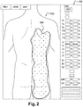
figure 2 , une étape de dessin d'une zone douloureuse sur ladite silhouette, selon un mode de réalisation du procédé de cartographie selon l'invention - A la
figure 3 , une étape d'affichage de dermatomes sur la silhouette, et de calcul de ratios de surface cutanée douloureuse correspondant à chacun de ces dermatomes - A la
figure 4 , des étapes d'un mode de réalisation du procédé de cartographie selon l'invention - A la
figure 5 , des étapes d'un procédé d'évaluation de l'efficacité d'une stimulation médullaire selon un mode de réalisation de l'invention - A la
figure 6 , une représentation schématique d'un système de cartographie et d'un système d'évaluation de l'efficacité d'une stimulation médullaire selon un mode de réalisation de l'invention.
- To the
figure 1 , a step of displaying a silhouette on a screen, according to an embodiment of the mapping method according to the invention - To the
figure 2 , a step of drawing a painful zone on said silhouette, according to an embodiment of the mapping method according to the invention - To the
figure 3 , a step of displaying dermatomes on the silhouette, and calculation of painful cutaneous surface ratios corresponding to each of these dermatomes - To the
figure 4 , Steps of an Embodiment of the Mapping Method According to the Invention - To the
figure 5 , Steps of a Method for Evaluating the Efficacy of a Medullary Stimulation According to an Embodiment of the Invention - To the
figure 6 , a schematic representation of a mapping system and a system for evaluating the efficacy of a medullary stimulation according to one embodiment of the invention.
Sauf précision contraire, un même élément apparaissant sur des figures différentes présente une référence unique.Unless otherwise specified, the same element appearing in different figures has a unique reference.
L'invention propose un procédé de cartographie de zones douloureuses, un procédé d'évaluation de l'efficacité d'une stimulation médullaire, un système de cartographie, et un système d'évaluation de l'efficacité d'une stimulation médullaire.The invention provides a method for mapping painful areas, a method for evaluating the efficacy of spinal cord stimulation, a mapping system, and a system for evaluating the effectiveness of spinal cord stimulation.
Le procédé de cartographie est destiné à :
- indiquer la localisation de douleurs ressenties par un patient,
- indiquer le type de ces douleurs (neuropathiques ou mécaniques) ressenties, et
- fournir des caractéristiques desdites douleurs. Ces caractéristiques sont notamment la surface cutanée concernée par la douleur, et le pourcentage de surface cutanée douloureuse comprise dans chaque dermatome ou chaque région lombaire.
- indicate the location of pain experienced by a patient,
- indicate the type of pain (neuropathic or mechanical) felt, and
- provide characteristics of said pains. These characteristics are in particular the cutaneous surface concerned by the pain, and the percentage of painful cutaneous surface included in each dermatome or each lumbar region.
Ces résultats permettent à un médecin de choisir une ou plusieurs électrodes à implanter au niveau de la ou les zones douloureuses, afin de mettre en oeuvre la technique de stimulation médullaire visant à soulager les douleurs du patient. En effet, en fonction des caractéristiques indiquées précédemment, certaines électrodes seront plus ou moins adaptées.These results allow a doctor to choose one or more electrodes to be implanted at the level or the painful areas, in order to implement the technique of spinal stimulation to relieve the pain of the patient. Indeed, depending on characteristics indicated above, some electrodes will be more or less suitable.
Plus précisément, en référence à la
- A1 : en référence à la
figure 1 , afficher une premièresilhouette 100 représentant la face postérieure d'un corps, sur unpremier écran 102. Le premier écran 102 est par exemple un écran tactile, avantageusement un écran de tablette tactile. En effet, un écran tactile permet une utilisation ergonomique, et une tablette tactile est de taille suffisamment grande pour permettre un affichage agréable, et suffisamment petite pour limiter l'encombrement. Dans le mode de réalisation décrit,la silhouette 100 est un modèle standard, non adaptée à la morphologie du patient. Cependant, un mode de réalisation dans lequel lasilhouette 100 est de forme adaptée à la morphologie du patient n'est pas exclu. - B1 : en référence à la
figure 2 , dessiner au moins une zone douloureuse 104 sur ladite première silhouette affichée 100, indiquant la localisation d'une douleur ressentie par le patient. Dans un mode de réalisation non limitatif dans lequel l'écran 102 est tactile, le patient délimite la zone douloureuse 104 en l'entourant avec son doigt. Dans un mode de réalisation, le patient dispose d'une palette de deux couleurs, chaque couleur représentant un type de douleur. Dans un autre mode de réalisation, la douleur est représentée d'une seule et même couleur mais des hachures permettent de différencier le type de douleur. Par type de douleur, on entend une douleur mécanique ou neuropathique. Des critères déterminés regroupés dans un questionnaire permettent de qualifier une douleur de neuropathique. Le patient peut ainsi indiquer si une zone douloureuse correspond à une douleur neuropathique ou à une douleur mécanique. - C1 : déterminer un premier nombre de pixels du
premier écran 102, correspondant à lazone douloureuse 104. On note que les nombres de pixels correspondant aux douleurs neuropathiques et mécaniques, ou à différentes zones douloureuses, s'ajoutent sauf dans le cas d'une intersection : dans ce cas, la surface commune n'est comptabilisée qu'une seule fois.
- D1 : mesurer une distance repère sur le patient. Dans le mode de réalisation décrit, la distance repère correspond à la distance entre les deux crêtes iliaques du patient. En effet, cette distance présente l'avantage d'être invariante selon la corpulence du patient. On note que d'autres repères morphologiques pourraient être utilisés, par exemple la distance entre les omoplates ou la distance entre les mastoïdes, mais la distance entre les crêtes iliaques est préférée. Il est entendu que l'étape de mesure de la distance repère peut être effectuée avant les étapes précédemment décrites, ou entre deux de ces étapes.
- E1 : convertir le premier nombre de pixels en une surface cutanée douloureuse, la distance repère intervenant comme paramètre de la conversion. La surface cutanée douloureuse est alors affichée sur le
premier écran 102, ce qui permet au médecin de disposer de l'information. La surface cutanée douloureuse est par exemple exprimée en centimètres carrés.
- A1: with reference to the
figure 1 displaying afirst silhouette 100 representing the rear face of a body, on afirst screen 102. Thefirst screen 102 is for example a touch screen, preferably a touch screen tablet. Indeed, a touch screen allows ergonomic use, and a touch pad is large enough to allow a pleasant display, and small enough to limit clutter. In the embodiment described, thesilhouette 100 is a standard model, not adapted to the morphology of the patient. However, an embodiment in which thesilhouette 100 is of a shape adapted to the morphology of the patient is not excluded. - B1: with reference to the
figure 2 draw at least onepainful zone 104 on said first displayedsilhouette 100, indicating the location of a pain felt by the patient. In a non-limiting embodiment in which thescreen 102 is tactile, the patient defines thepainful zone 104 by surrounding it with his finger. In one embodiment, the patient has a palette of two colors, each color representing a type of pain. In another embodiment, the pain is represented in one and the same color, but hatching makes it possible to differentiate the type of pain. By type of pain is meant mechanical or neuropathic pain. Specific criteria grouped in a questionnaire make it possible to qualify a neuropathic pain. The patient can indicate whether a painful area corresponds to neuropathic pain or mechanical pain. - C1: determining a first number of pixels of the
first screen 102, corresponding to thepain zone 104. It is noted that the numbers of pixels corresponding to the neuropathic and mechanical pains, or to different painful zones, are added except in the case of an intersection: in this case, the common surface is counted only once.
- D1: measure a reference distance on the patient. In the embodiment described, the reference distance corresponds to the distance between the two iliac crests of the patient. Indeed, this distance has the advantage of being invariant according to the corpulence of the patient. It is noted that other morphological landmarks could be used, for example the distance between the shoulder blades or the distance between the mastoids, but the distance between the iliac crests is preferred. It is understood that the step of measuring the reference distance can be performed before the previously described steps, or between two of these steps.
- E1: convert the first number of pixels into a painful skin surface, the reference distance acting as a parameter of the conversion. The painful skin surface is then displayed on the
first screen 102, which allows the doctor to have the information. The painful skin surface is for example expressed in square centimeters.
Pour réaliser cette étape de conversion, deux coefficients sont calculés :
- un coefficient vertical égal à taille réelle du patient divisée par le nombre de pixels représentant la taille de la silhouette
- un coefficient horizontal égal à distance entre les crêtes iliaques du patient divisée par le nombre de pixels représentant la distance entre les crêtes iliaques sur la silhouette.
- a vertical coefficient equal to the actual size of the patient divided by the number of pixels representing the size of the silhouette
- a horizontal coefficient equal at a distance between the patient's iliac crests divided by the number of pixels representing the distance between the iliac crests on the silhouette.
La surface cutanée douloureuse est alors égale au produit du coefficient horizontal, du coefficient vertical et du premier nombre de pixel correspondant à la zone douloureuse.
- F1 : déterminer un ratio de surface cutanée douloureuse comprise dans une région 106 de la première
silhouette 100. En référence à lafigure 3 , dans un mode de réalisation, la région 106 considérée correspond à un dermatome. Dans un mode de réalisation, les régions 106 sont affichées sur lasilhouette 100, superposées à la zone douloureuse 104 dessinée. La région 106 pourrait également être une région lombaire, ou toute autre région correspondant à une notion topographique connue. Avantageusement, plusieurs ratios correspondant à plusieurs régions 106 d'un référentiel topographique sont calculés. Dans un mode de réalisation, ces ratios sont exprimés en pourcentage afin d'en faciliter la lecture. Le médecin peut ainsi savoir quels dermatomes sont engagés par la douleur, et en quelles proportions. Dans un mode de réalisation, un tableau de correspondance est affiché à côté de la premièresilhouette 100, montrant les ratios ou les pourcentages de surface cutanée douloureuse par région considérée. La surface cutanée douloureuse est ainsi exprimée en pourcentages par rapport à la représentation surfacique des différents dermatomes de la région dorso-lombaire en particulier. - G1 : dans un mode de réalisation, la première
silhouette 100 sur laquelle sont dessinées la ou les zones douloureuses 104, ainsi que les caractéristiques de ces douleurs, sont enregistrées sur un serveur.
- F1: to determine a painful cutaneous surface ratio included in a
region 106 of thefirst silhouette 100. With reference to thefigure 3 in one embodiment, theregion 106 considered corresponds to a dermatome. In a mode of realization, theregions 106 are displayed on thesilhouette 100, superimposed on thepainful zone 104 drawn. Theregion 106 could also be a lumbar region, or any other region corresponding to a known topographical concept. Advantageously, several ratios corresponding toseveral regions 106 of a topographic reference system are calculated. In one embodiment, these ratios are expressed as a percentage in order to facilitate reading. The doctor can know which dermatomes are involved in the pain, and in what proportions. In one embodiment, a correspondence table is displayed next to thefirst silhouette 100, showing the ratios or percentages of painful skin area by region considered. The painful skin surface is thus expressed in percentages relative to the surface representation of the various dermatomes of the dorsolumbar region in particular. - G1: In one embodiment, the
first silhouette 100 on which the painful zone orzones 104 are drawn, as well as the characteristics of these pain, are recorded on a server.
Le procédé de cartographie 400 peut être mis en oeuvre à différents moments dans l'espace temporel pour un patient donné. On obtient ainsi une cartographie initiale et des cartographies de suivi, ce qui permet de comparer la région douloureuse avant et après que le patient ait reçu un traitement donné et en particulier une implantation de stimulation médullaire. Les évaluations peuvent être également répétées dans le temps et à plusieurs moments de la journée ce qui permet, par implémentation de données, d'arriver à une approximation moyennée des régions douloureuses plus précise dans le temps.The
Le procédé d'évaluation de l'efficacité d'une stimulation médullaire est utilisé pour :
- lors d'une opération d'implantation d'une ou plusieurs électrodes sur le patient, savoir si l'électrode est bien positionnée ou s'il est avantageux de la déplacer, et/ou
- en post-opératoire, faire un suivi du patient, c'est-à-dire vérifier que la stimulation médullaire est (encore) efficace, et si elle soulage en effet le patient sur l'intégralité des zones douloureuses.
- during an implantation operation of one or more electrodes on the patient, to know if the electrode is well positioned or if it is advantageous to move it, and / or
- postoperatively, follow up the patient, that is to say, verify that the spinal stimulation is (still) effective, and if it relieves indeed the patient on the entirety of the painful areas.
Plus précisément, en référence à la
- A2 : réaliser les étapes du procédé de cartographie 400 précédemment décrit.
- B2 : réaliser une stimulation médullaire sur le patient à l'aide d'au moins une électrode. Dans un mode de réalisation, l'électrode a été préalablement implantée lors d'une opération chirurgicale au niveau de la zone douloureuse 104 ressentie par le patient. Dans un autre mode de réalisation, la stimulation médullaire est réalisée lors d'une opération chirurgicale destinée à implanter l'électrode.
- C2 : afficher une deuxième silhouette représentant sensiblement identique à la première
silhouette 100, sur un deuxième écran. Le deuxième écran est par exemple un écran tactile, avantageusement un écran de tablette tactile. Dans un mode de réalisation non limitatif, le deuxième écran est le premier écran précédemment évoqué. - D2 : dessiner au moins une zone de paresthésie sur la deuxième silhouette affichée, indiquant la localisation d'une paresthésie ressentie par le patient en réponse à la stimulation médullaire.
- E2 : déterminer un deuxième nombre de pixels du deuxième écran, correspondant à la zone de paresthésie.
- F2 : convertir le deuxième nombre de pixels en une surface cutanée paresthésie, la distance repère précédemment évoquée intervenant comme paramètre de la conversion. La conversion est effectuée de la même manière qu'à l'étape E1 du procédé de cartographie 400. La surface cutanée paresthésique est alors affichée sur le deuxième écran, ce qui permet au médecin de disposer de l'information.
- G2 : comparer la surface cutanée paresthésique à la surface cutanée douloureuse déterminée lors de l'étape E1 du procédé de cartographie 400.
- H2 : superposer la deuxième silhouette et la première
silhouette 100 sur le deuxième écran ou sur lepremier écran 102. - I2 : dans un mode de réalisation, la deuxième silhouette sur laquelle sont dessinées la ou les zones de paresthésie, ainsi que la surface cutanée paresthésique, sont enregistrées sur le serveur.
- A2: carry out the steps of the
mapping method 400 previously described. - B2: perform spinal stimulation on the patient using at least one electrode. In one embodiment, the electrode has been previously implanted during a surgical operation at the
pain zone 104 felt by the patient. In another embodiment, the medullary stimulation is performed during a surgical procedure for implanting the electrode. - C2: display a second silhouette representing substantially identical to the
first silhouette 100, on a second screen. The second screen is for example a touch screen, preferably a touch screen tablet. In a non-limiting embodiment, the second screen is the first screen previously mentioned. - D2: draw at least one area of paresthesia on the second displayed silhouette, indicating the location of a paresthesia felt by the patient in response to the medullary stimulation.
- E2: determine a second number of pixels of the second screen, corresponding to the paraesthesia zone.
- F2: convert the second number of pixels into a cutaneous surface paresthesia, the reference distance previously mentioned as a parameter of the conversion. The conversion is performed in the same way as in step E1 of
Mapping process 400. The paresthetic skin surface is then displayed on the second screen, which allows the doctor to have the information. - G2: compare the paresthetic cutaneous surface to the painful skin surface determined during the step E1 of the
mapping process 400. - H2: superimpose the second silhouette and the
first silhouette 100 on the second screen or on thefirst screen 102. - I2: in one embodiment, the second silhouette on which are drawn the paresthesia zone (s), as well as the paresthetic cutaneous surface, are recorded on the server.
En référence à la
- Des moyens d'affichage 610 d'une silhouette représentant la face postérieure d'un corps, sur un écran
- Des moyens de dessin 620 d'au moins une zone sur ladite silhouette
- Des moyens de détermination 630 d'un nombre de pixels de l'écran, correspondant à ladite zone
- Des moyens de
conversion 640 dudit nombre de pixels en une surface cutanée, au moyen d'une distance repère intervenant comme paramètre de ladite conversion. - Des moyens de détermination 650 d'un ratio de ladite surface cutanée comprise dans une région de la silhouette
- Des moyens de comparaison 660 de la surface cutanée à une deuxième surface cutanée préalablement déterminée.
- Display means 610 of a silhouette representing the posterior face of a body, on a screen
- Drawing means 620 of at least one zone on said silhouette
- Means for determining a number of pixels of the screen corresponding to said zone
- Conversion means 640 of said number of pixels to a cutaneous surface, by means of a reference distance intervening as a parameter of said conversion.
-
Means 650 for determining a ratio of said cutaneous surface comprised in a region of the silhouette - Comparison means 660 of the cutaneous surface to a second predetermined skin surface.
Le système de cartographie 600 permet de mettre en oeuvre le procédé de cartographie 400 selon l'invention. Les zones dessinées peuvent correspondre à des zones douloureuses ou à des zones de paresthésie ressenties suite à une stimulation médullaire.The
Le système d'évaluation de l'efficacité d'une stimulation médullaire 700 comporte :
- Le système de cartographie 600
- Des moyens de
stimulation médullaire 710. Classiquement, il s'agit d'au moins une électrode multi contacts implantée sous la peau du patient, reliée à un boîtier de commande. - Des moyens de comparaison 720 d'une surface cutanée douloureuse à une surface cutanée paresthésique, ladite paresthésie étant ressentie en réponse à une stimulation médullaire par les moyens de stimulation médullaire
- Des moyens de calcul 730 d'un pourcentage de recouvrement de la surface cutanée douloureuse par la surface cutanée paresthésique.
- The
mapping system 600 - Medullary stimulation means 710. Conventionally, it is at least one multi-contact electrode implanted under the skin of the patient, connected to a control box.
- Comparison means 720 of a painful cutaneous surface to a paresthetic cutaneous surface, said paresthesia being felt in response to medullary stimulation by the spinal stimulation means
- Computing means 730 of a percentage of recovery of the painful cutaneous surface by the cutaneous surface paresthetic.
Le système d'évaluation de l'efficacité d'une stimulation médullaire 700 permet de mettre en oeuvre le procédé d'évaluation de l'efficacité d'une stimulation médullaire 500.The system for evaluating the effectiveness of a
Claims (13)
- Method for mapping (400) painful zones, including the following steps:- Displaying (A1) a first silhouette (100) representing the rear face of a body, on a first screen (102)- Drawing (B1) at least one painful zone (104) on said first displayed silhouette (100), indicating the location of a pain felt by a patient- Determining (C1) a first number of pixels on the first screen (102), corresponding to said painful zone (104),characterized in that:- Measuring (D1) a reference distance between two morphological reference points on the patient, calculate a horizontal coefficient equal to the distance between the two morphological reference points on the patient divided by the number of pixels representing the distance between the two morphological reference points on the silhouette,- Calculate a vertical coefficient equal to the actual size of the patient divided by the number of pixels representing the size of the silhouette,- Converting (E1) said first number of pixels into a painful cutaneous surface, said horizontal and vertical coefficient being used as a parameter in said conversion.
- Method for mapping (400) according to the preceding claim, characterised in that the morphological reference points are the iliac crests of the patient.
- Method for mapping (400) according to one of the preceding claims, characterised in that it includes the following step:- Correcting the converted painful cutaneous surface with the aid of a correction coefficient.
- Method for mapping (400) according to one of the preceding claims, characterised in that it includes the following step:- Determining (F1) a ratio of painful cutaneous surface comprised in a region (106) of the first silhouette (100).
- Method for mapping (400) according to one of the preceding claims, characterized in that the step of drawing (B1) at least one painful zone (104) comprises the following sub-steps:- Drawing in a first manner a neuropathic pain- Drawing in a second manner a mechanical pain.
- Method for evaluating the efficacy of medullary stimulation (500), including the following steps:- Determining a painful cutaneous surface by the method for mapping according to one of the preceding claims,- Displaying (C2) a second silhouette representing the rear face of a body, on a second screen- Drawing (D2) at least one paraesthesia zone on said second displayed silhouette, indicating the location of a paraesthesia felt by the patient in response to medullary stimulation- Determining (E2) a second number of pixels on the second screen, corresponding to said paraesthesia zone- Converting (F2) said second number of pixels into a paraesthesic cutaneous surface, the reference distance being used as a parameter in said conversion,- Comparing (G2) the paraesthesic cutaneous surface with the painful cutaneous surface determined beforehand by the mapping method according to any of the preceding claims.
- Method for evaluating the efficacy of medullary stimulation (500) according to the preceding claim, characterised in that the comparison step (G2) comprises the following sub-step:- Calculating a percentage coverage of the painful cutaneous surface by the paraesthesic cutaneous surface.
- Mapping system (600), including:- Means for displaying (610) a silhouette (100) representing the rear face of a body, on a screen (102)- Means for drawing (620) at least one zone (104) on said silhouette (100)- Means for determining (630) a number of pixels on the screen (102), corresponding to said zone (104),characterized by :- Means for converting (640) said number of pixels into a cutaneous surface, by means of a vertical coefficient equal to the actual size of the patient divided by the number of pixels representing the size of the silhouette, and
a horizontal coefficient calculated from a distance between two morphological reference points on the patient divided by the number of pixels representing the distance between the two morphological reference points on the silhouette of being used as a parameter in said conversion. - Mapping system (600) according to claim 8, including:- Means for correcting the converted cutaneous surface by means of a correction coefficient.
- Mapping system (600) according to one of claims 8 or 9, including:- Means for determining a ratio of said cutaneous surface comprised in a region (106) of the silhouette (100).
- Mapping system (600) according to one of claims 8 to 10, including:- Means for comparing the cutaneous surface with a second cutaneous surface determined beforehand.
- System for evaluating the efficacy of medullary stimulation (700), including:- The mapping system (600) according to one of claims 8 to 11- Medullary stimulation means (710)- Means for comparing (720) a painful cutaneous surface with a paraesthesic cutaneous surface, said paraesthesia being felt in response to medullary stimulation by the medullary stimulation means.
- System for evaluating the efficacy of medullary stimulation (700) according to claim 12, including:- Means for calculating (730) a percentage coverage of the painful cutaneous surface by the paraesthesic cutaneous surface.
Applications Claiming Priority (2)
| Application Number | Priority Date | Filing Date | Title |
|---|---|---|---|
| FR1358850A FR3010624B1 (en) | 2013-09-13 | 2013-09-13 | METHOD AND SYSTEM FOR CARTOGRAPHY, METHOD AND SYSTEM FOR EVALUATING THE EFFECTIVENESS OF MEDULINALLY STIMULATING |
| PCT/EP2014/067231 WO2015036191A1 (en) | 2013-09-13 | 2014-08-12 | Mapping method and system, method and system for evaluating the efficacy of medullary simulation |
Publications (2)
| Publication Number | Publication Date |
|---|---|
| EP3043705A1 EP3043705A1 (en) | 2016-07-20 |
| EP3043705B1 true EP3043705B1 (en) | 2019-10-02 |
Family
ID=49998364
Family Applications (3)
| Application Number | Title | Priority Date | Filing Date |
|---|---|---|---|
| EP14752814.5A Active EP3043705B1 (en) | 2013-09-13 | 2014-08-12 | Mapping method and system, method and system for evaluating the efficacy of medullary simulation |
| EP14756088.2A Active EP3043706B1 (en) | 2013-09-13 | 2014-08-14 | Device and method for evaluating and monitoring physical pain |
| EP14758999.8A Active EP3043707B1 (en) | 2013-09-13 | 2014-08-14 | Device for evaluating pain |
Family Applications After (2)
| Application Number | Title | Priority Date | Filing Date |
|---|---|---|---|
| EP14756088.2A Active EP3043706B1 (en) | 2013-09-13 | 2014-08-14 | Device and method for evaluating and monitoring physical pain |
| EP14758999.8A Active EP3043707B1 (en) | 2013-09-13 | 2014-08-14 | Device for evaluating pain |
Country Status (5)
| Country | Link |
|---|---|
| US (3) | US10058280B2 (en) |
| EP (3) | EP3043705B1 (en) |
| DK (3) | DK3043705T3 (en) |
| FR (1) | FR3010624B1 (en) |
| WO (3) | WO2015036191A1 (en) |
Families Citing this family (30)
| Publication number | Priority date | Publication date | Assignee | Title |
|---|---|---|---|---|
| US7959598B2 (en) | 2008-08-20 | 2011-06-14 | Asante Solutions, Inc. | Infusion pump systems and methods |
| US9452294B2 (en) * | 2013-05-16 | 2016-09-27 | Nuvectra Corporation | Automatic current balancing with lock control for a clinician programmer |
| US11227427B2 (en) * | 2014-08-11 | 2022-01-18 | Covidien Lp | Treatment procedure planning system and method |
| USD777191S1 (en) * | 2015-04-16 | 2017-01-24 | Polimeni Medical Information Technologies, LLC | Display panel of a programmed computer system with a graphical user interface |
| US11363985B2 (en) * | 2015-04-17 | 2022-06-21 | Nanolume, LLC | Systems and methods for pain tracking |
| EP3302236B1 (en) * | 2015-06-03 | 2020-04-01 | Boston Scientific Neuromodulation Corporation | System for pain assesment |
| EP3374905A1 (en) | 2016-01-13 | 2018-09-19 | Bigfoot Biomedical, Inc. | User interface for diabetes management system |
| CN108495665B (en) | 2016-01-14 | 2021-04-09 | 比格福特生物医药公司 | Adjusting insulin delivery rate |
| USD855064S1 (en) * | 2016-09-21 | 2019-07-30 | Analytics For Life Inc. | Display screen with graphical user interface |
| WO2018071865A1 (en) * | 2016-10-14 | 2018-04-19 | Boston Scientific Neuromodulation Corporation | Systems and methods for closed-loop determination of stimulation parameter settings for an electrical simulation system |
| USD836123S1 (en) * | 2017-06-08 | 2018-12-18 | Insulet Corporation | Display screen with a graphical user interface |
| JP1607361S (en) * | 2017-06-23 | 2018-06-25 | ||
| USD928199S1 (en) | 2018-04-02 | 2021-08-17 | Bigfoot Biomedical, Inc. | Medication delivery device with icons |
| USD999246S1 (en) * | 2018-10-11 | 2023-09-19 | Masimo Corporation | Display screen or portion thereof with a graphical user interface |
| USD998631S1 (en) * | 2018-10-11 | 2023-09-12 | Masimo Corporation | Display screen or portion thereof with a graphical user interface |
| USD917564S1 (en) * | 2018-10-11 | 2021-04-27 | Masimo Corporation | Display screen or portion thereof with graphical user interface |
| USD917550S1 (en) | 2018-10-11 | 2021-04-27 | Masimo Corporation | Display screen or portion thereof with a graphical user interface |
| USD998630S1 (en) | 2018-10-11 | 2023-09-12 | Masimo Corporation | Display screen or portion thereof with a graphical user interface |
| USD916135S1 (en) * | 2018-10-11 | 2021-04-13 | Masimo Corporation | Display screen or portion thereof with a graphical user interface |
| JP1659823S (en) * | 2019-07-11 | 2020-05-18 | ||
| JP1659868S (en) * | 2019-07-11 | 2020-05-18 | ||
| JP1659867S (en) * | 2019-07-11 | 2020-05-18 | ||
| JP1655462S (en) * | 2019-07-11 | 2020-03-23 | ||
| US20210074176A1 (en) * | 2019-09-06 | 2021-03-11 | Rocio Elisa Hernández | Bilateral stimulation method and apparatus |
| USD952666S1 (en) | 2019-10-02 | 2022-05-24 | Javad Abbas Sajan | Display screen or portion thereof with graphical user interface |
| USD939525S1 (en) * | 2019-11-27 | 2021-12-28 | GE Precision Healthcare LLC | Display screen with graphical user interface |
| USD934898S1 (en) * | 2020-04-21 | 2021-11-02 | Annalise AI Pty Ltd | Display screen or portion thereof with a transitional graphical user interface for annotating radioanatomy images |
| USD977502S1 (en) | 2020-06-09 | 2023-02-07 | Insulet Corporation | Display screen with graphical user interface |
| WO2023200583A1 (en) * | 2022-04-12 | 2023-10-19 | Boston Scientific Neuromodulation Corporation | System for neuromodulation guidance using symptom-wise sensory profile |
| CN115019948B (en) * | 2022-06-28 | 2023-06-16 | 苏州景昱医疗器械有限公司 | Control device, remote consultation system, and computer-readable storage medium |
Family Cites Families (14)
| Publication number | Priority date | Publication date | Assignee | Title |
|---|---|---|---|---|
| EP0618528B1 (en) | 1993-04-01 | 1999-12-29 | International Business Machines Corporation | Dynamic touchscreen button adjustment mechanism |
| US6308102B1 (en) * | 1999-09-29 | 2001-10-23 | Stimsoft, Inc. | Patient interactive neurostimulation system and method |
| US6654642B2 (en) * | 1999-09-29 | 2003-11-25 | Medtronic, Inc. | Patient interactive neurostimulation system and method |
| US6529195B1 (en) * | 2000-09-08 | 2003-03-04 | James B. Eberlein | Pain migration tracking and display method |
| AU2003285078A1 (en) * | 2002-10-31 | 2004-06-07 | Medtronic, Inc. | Distributed system for neurostimulation therapy programming |
| AU2003288959A1 (en) * | 2002-10-31 | 2004-06-07 | Medtronic, Inc. | Body region indication |
| US7374536B1 (en) * | 2004-04-16 | 2008-05-20 | Taylor Colin R | Method for analysis of pain images |
| US7894905B2 (en) * | 2006-03-13 | 2011-02-22 | Neuropace, Inc. | Implantable system enabling responsive therapy for pain |
| US8046241B1 (en) * | 2007-02-05 | 2011-10-25 | Dodson William H | Computer pain assessment tool |
| US8021298B2 (en) * | 2007-06-28 | 2011-09-20 | Psychological Applications Llc | System and method for mapping pain depth |
| JP2010019953A (en) * | 2008-07-09 | 2010-01-28 | Seiko Epson Corp | Screen |
| CN101727243B (en) | 2010-02-02 | 2014-04-30 | 中兴通讯股份有限公司 | Method and device for acquiring calibration parameters of touch screen |
| US9615788B2 (en) * | 2012-08-31 | 2017-04-11 | Nuvectra Corporation | Method and system of producing 2D representations of 3D pain and stimulation maps and implant models on a clinician programmer |
| WO2014037939A1 (en) * | 2012-09-05 | 2014-03-13 | Body Pass Ltd. | System and method for deriving accurate body size measures from a sequence of 2d images |
-
2013
- 2013-09-13 FR FR1358850A patent/FR3010624B1/en active Active
-
2014
- 2014-08-12 US US15/021,337 patent/US10058280B2/en active Active
- 2014-08-12 WO PCT/EP2014/067231 patent/WO2015036191A1/en active Application Filing
- 2014-08-12 DK DK14752814.5T patent/DK3043705T3/en active
- 2014-08-12 EP EP14752814.5A patent/EP3043705B1/en active Active
- 2014-08-14 US US15/021,390 patent/US9999387B2/en active Active
- 2014-08-14 DK DK14756088.2T patent/DK3043706T3/en active
- 2014-08-14 EP EP14756088.2A patent/EP3043706B1/en active Active
- 2014-08-14 EP EP14758999.8A patent/EP3043707B1/en active Active
- 2014-08-14 WO PCT/FR2014/000186 patent/WO2015036660A1/en active Application Filing
- 2014-08-14 DK DK14758999.8T patent/DK3043707T3/en active
- 2014-08-14 US US15/021,399 patent/US9986946B2/en active Active
- 2014-08-14 WO PCT/FR2014/000187 patent/WO2015036661A1/en active Application Filing
Non-Patent Citations (1)
| Title |
|---|
| None * |
Also Published As
| Publication number | Publication date |
|---|---|
| US20160220178A1 (en) | 2016-08-04 |
| EP3043705A1 (en) | 2016-07-20 |
| WO2015036660A1 (en) | 2015-03-19 |
| US9986946B2 (en) | 2018-06-05 |
| WO2015036661A1 (en) | 2015-03-19 |
| DK3043705T3 (en) | 2019-12-16 |
| US9999387B2 (en) | 2018-06-19 |
| EP3043706A1 (en) | 2016-07-20 |
| DK3043706T3 (en) | 2018-01-29 |
| FR3010624A1 (en) | 2015-03-20 |
| EP3043707A1 (en) | 2016-07-20 |
| FR3010624B1 (en) | 2015-09-25 |
| DK3043707T3 (en) | 2018-11-12 |
| US20160220179A1 (en) | 2016-08-04 |
| EP3043706B1 (en) | 2017-10-25 |
| WO2015036191A1 (en) | 2015-03-19 |
| US10058280B2 (en) | 2018-08-28 |
| US20160220181A1 (en) | 2016-08-04 |
| EP3043707B1 (en) | 2018-08-01 |
Similar Documents
| Publication | Publication Date | Title |
|---|---|---|
| EP3043705B1 (en) | Mapping method and system, method and system for evaluating the efficacy of medullary simulation | |
| Johnson et al. | Transcutaneous electrical nerve stimulation (TENS) for phantom pain and stump pain following amputation in adults | |
| Bierer et al. | Identifying cochlear implant channels with poor electrode-neuron interface: partial tripolar, single-channel thresholds and psychophysical tuning curves | |
| EP3302236B1 (en) | System for pain assesment | |
| Arribas et al. | The EHRA white book | |
| Karl et al. | A novel DBS paradigm for axial features in Parkinson's disease: a randomized crossover study | |
| US20210330240A1 (en) | Rapid mapping of language function and motor function without subject participation | |
| Levine et al. | Cervical spinal cord and dorsal nerve root stimulation for neuropathic upper limb pain | |
| Larzabal et al. | Long-term stability of the chronic epidural wireless recorder WIMAGINE in tetraplegic patients | |
| Hey et al. | The Intra-cochlear Impedance-Matrix (IIM) test for the Nucleus® cochlear implant | |
| Sokal et al. | Sub-perception and supra-perception spinal cord stimulation in chronic pain syndrome: a randomized, semi-double-blind, crossover, placebo-controlled trial | |
| Tang et al. | Effects of semicircular canal electrode implantation on hearing in chinchillas | |
| van Wermeskerken et al. | A comparison of intra-versus post-operatively acquired electrically evoked compound action potentials: Comparación intra y post-operatoria de los potenciales compuestos de acción adquiridos y evocados eléctricamente | |
| US20110275953A1 (en) | Hearing Treatment In Patients With Questionable Cochlear Nerve Functionality | |
| Böttcher-Rebmann et al. | Preclinical evaluation of a tool for insertion force measurements in cochlear implant surgery | |
| Soulby et al. | Establishing reproducibility and correlation of cochlear microphonic amplitude to implant electrode position using intraoperative electrocochleography and postoperative cone beam computed tomography | |
| Jayakumar et al. | Sparseness of coding in area 17 of the cat visual cortex: a comparison between pinwheel centres and orientation domains | |
| Salmon et al. | Treating Chronic, Intractable Pain with a Miniaturized Spinal Cord Stimulation System: 1-Year Outcomes from the AUS-nPower Study During the COVID-19 Pandemic | |
| Cakir | Use of patient-specific models for computer-assisted cochlear implant programming | |
| Bonne et al. | Impact of modulating phase duration on electrically evoked auditory brainstem responses obtained during cochlear implantation | |
| Manrique et al. | Promontorial cochleostomy in nonhuman primates. Is it atraumatic? | |
| Sainz et al. | Transitory alterations of the electrode impedances in cochlear implants associated to middle and inner ear diseases | |
| Bauer | Method for acute Neuropixels probe recordings in non-human primates | |
| Lorens et al. | Pitch perception and the number of electrodes vs. long-term development of speech perception ability in auditory brainstem implants | |
| Reaney et al. | Therapeutic Success or Failure: A Journey, Not Just a Destination |
Legal Events
| Date | Code | Title | Description |
|---|---|---|---|
| PUAI | Public reference made under article 153(3) epc to a published international application that has entered the european phase |
Free format text: ORIGINAL CODE: 0009012 |
|
| 17P | Request for examination filed |
Effective date: 20160229 |
|
| AK | Designated contracting states |
Kind code of ref document: A1 Designated state(s): AL AT BE BG CH CY CZ DE DK EE ES FI FR GB GR HR HU IE IS IT LI LT LU LV MC MK MT NL NO PL PT RO RS SE SI SK SM TR |
|
| AX | Request for extension of the european patent |
Extension state: BA ME |
|
| STAA | Information on the status of an ep patent application or granted ep patent |
Free format text: STATUS: REQUEST FOR EXAMINATION WAS MADE |
|
| DAX | Request for extension of the european patent (deleted) | ||
| STAA | Information on the status of an ep patent application or granted ep patent |
Free format text: STATUS: EXAMINATION IS IN PROGRESS |
|
| 17Q | First examination report despatched |
Effective date: 20170630 |
|
| GRAP | Despatch of communication of intention to grant a patent |
Free format text: ORIGINAL CODE: EPIDOSNIGR1 |
|
| STAA | Information on the status of an ep patent application or granted ep patent |
Free format text: STATUS: GRANT OF PATENT IS INTENDED |
|
| RIC1 | Information provided on ipc code assigned before grant |
Ipc: G16H 40/63 20180101ALI20190312BHEP Ipc: A61B 5/107 20060101AFI20190312BHEP Ipc: A61B 5/00 20060101ALI20190312BHEP |
|
| INTG | Intention to grant announced |
Effective date: 20190408 |
|
| GRAS | Grant fee paid |
Free format text: ORIGINAL CODE: EPIDOSNIGR3 |
|
| GRAA | (expected) grant |
Free format text: ORIGINAL CODE: 0009210 |
|
| STAA | Information on the status of an ep patent application or granted ep patent |
Free format text: STATUS: THE PATENT HAS BEEN GRANTED |
|
| AK | Designated contracting states |
Kind code of ref document: B1 Designated state(s): AL AT BE BG CH CY CZ DE DK EE ES FI FR GB GR HR HU IE IS IT LI LT LU LV MC MK MT NL NO PL PT RO RS SE SI SK SM TR |
|
| REG | Reference to a national code |
Ref country code: GB Ref legal event code: FG4D Free format text: NOT ENGLISH |
|
| REG | Reference to a national code |
Ref country code: CH Ref legal event code: EP Ref country code: AT Ref legal event code: REF Ref document number: 1185290 Country of ref document: AT Kind code of ref document: T Effective date: 20191015 |
|
| REG | Reference to a national code |
Ref country code: DE Ref legal event code: R096 Ref document number: 602014054575 Country of ref document: DE |
|
| REG | Reference to a national code |
Ref country code: IE Ref legal event code: FG4D Free format text: LANGUAGE OF EP DOCUMENT: FRENCH |
|
| REG | Reference to a national code |
Ref country code: DK Ref legal event code: T3 Effective date: 20191213 |
|
| REG | Reference to a national code |
Ref country code: NL Ref legal event code: FP |
|
| REG | Reference to a national code |
Ref country code: LT Ref legal event code: MG4D |
|
| REG | Reference to a national code |
Ref country code: CH Ref legal event code: NV Representative=s name: VALIPAT S.A. C/O BOVARD SA NEUCHATEL, CH |
|
| REG | Reference to a national code |
Ref country code: AT Ref legal event code: MK05 Ref document number: 1185290 Country of ref document: AT Kind code of ref document: T Effective date: 20191002 |
|
| PG25 | Lapsed in a contracting state [announced via postgrant information from national office to epo] |
Ref country code: ES Free format text: LAPSE BECAUSE OF FAILURE TO SUBMIT A TRANSLATION OF THE DESCRIPTION OR TO PAY THE FEE WITHIN THE PRESCRIBED TIME-LIMIT Effective date: 20191002 Ref country code: AT Free format text: LAPSE BECAUSE OF FAILURE TO SUBMIT A TRANSLATION OF THE DESCRIPTION OR TO PAY THE FEE WITHIN THE PRESCRIBED TIME-LIMIT Effective date: 20191002 Ref country code: LT Free format text: LAPSE BECAUSE OF FAILURE TO SUBMIT A TRANSLATION OF THE DESCRIPTION OR TO PAY THE FEE WITHIN THE PRESCRIBED TIME-LIMIT Effective date: 20191002 Ref country code: NO Free format text: LAPSE BECAUSE OF FAILURE TO SUBMIT A TRANSLATION OF THE DESCRIPTION OR TO PAY THE FEE WITHIN THE PRESCRIBED TIME-LIMIT Effective date: 20200102 Ref country code: PL Free format text: LAPSE BECAUSE OF FAILURE TO SUBMIT A TRANSLATION OF THE DESCRIPTION OR TO PAY THE FEE WITHIN THE PRESCRIBED TIME-LIMIT Effective date: 20191002 Ref country code: GR Free format text: LAPSE BECAUSE OF FAILURE TO SUBMIT A TRANSLATION OF THE DESCRIPTION OR TO PAY THE FEE WITHIN THE PRESCRIBED TIME-LIMIT Effective date: 20200103 Ref country code: BG Free format text: LAPSE BECAUSE OF FAILURE TO SUBMIT A TRANSLATION OF THE DESCRIPTION OR TO PAY THE FEE WITHIN THE PRESCRIBED TIME-LIMIT Effective date: 20200102 Ref country code: FI Free format text: LAPSE BECAUSE OF FAILURE TO SUBMIT A TRANSLATION OF THE DESCRIPTION OR TO PAY THE FEE WITHIN THE PRESCRIBED TIME-LIMIT Effective date: 20191002 Ref country code: PT Free format text: LAPSE BECAUSE OF FAILURE TO SUBMIT A TRANSLATION OF THE DESCRIPTION OR TO PAY THE FEE WITHIN THE PRESCRIBED TIME-LIMIT Effective date: 20200203 Ref country code: SE Free format text: LAPSE BECAUSE OF FAILURE TO SUBMIT A TRANSLATION OF THE DESCRIPTION OR TO PAY THE FEE WITHIN THE PRESCRIBED TIME-LIMIT Effective date: 20191002 Ref country code: LV Free format text: LAPSE BECAUSE OF FAILURE TO SUBMIT A TRANSLATION OF THE DESCRIPTION OR TO PAY THE FEE WITHIN THE PRESCRIBED TIME-LIMIT Effective date: 20191002 |
|
| PG25 | Lapsed in a contracting state [announced via postgrant information from national office to epo] |
Ref country code: RS Free format text: LAPSE BECAUSE OF FAILURE TO SUBMIT A TRANSLATION OF THE DESCRIPTION OR TO PAY THE FEE WITHIN THE PRESCRIBED TIME-LIMIT Effective date: 20191002 Ref country code: HR Free format text: LAPSE BECAUSE OF FAILURE TO SUBMIT A TRANSLATION OF THE DESCRIPTION OR TO PAY THE FEE WITHIN THE PRESCRIBED TIME-LIMIT Effective date: 20191002 Ref country code: IS Free format text: LAPSE BECAUSE OF FAILURE TO SUBMIT A TRANSLATION OF THE DESCRIPTION OR TO PAY THE FEE WITHIN THE PRESCRIBED TIME-LIMIT Effective date: 20200224 Ref country code: CZ Free format text: LAPSE BECAUSE OF FAILURE TO SUBMIT A TRANSLATION OF THE DESCRIPTION OR TO PAY THE FEE WITHIN THE PRESCRIBED TIME-LIMIT Effective date: 20191002 |
|
| PG25 | Lapsed in a contracting state [announced via postgrant information from national office to epo] |
Ref country code: AL Free format text: LAPSE BECAUSE OF FAILURE TO SUBMIT A TRANSLATION OF THE DESCRIPTION OR TO PAY THE FEE WITHIN THE PRESCRIBED TIME-LIMIT Effective date: 20191002 |
|
| REG | Reference to a national code |
Ref country code: DE Ref legal event code: R097 Ref document number: 602014054575 Country of ref document: DE |
|
| PG2D | Information on lapse in contracting state deleted |
Ref country code: IS |
|
| PG25 | Lapsed in a contracting state [announced via postgrant information from national office to epo] |
Ref country code: EE Free format text: LAPSE BECAUSE OF FAILURE TO SUBMIT A TRANSLATION OF THE DESCRIPTION OR TO PAY THE FEE WITHIN THE PRESCRIBED TIME-LIMIT Effective date: 20191002 Ref country code: RO Free format text: LAPSE BECAUSE OF FAILURE TO SUBMIT A TRANSLATION OF THE DESCRIPTION OR TO PAY THE FEE WITHIN THE PRESCRIBED TIME-LIMIT Effective date: 20191002 Ref country code: IS Free format text: LAPSE BECAUSE OF FAILURE TO SUBMIT A TRANSLATION OF THE DESCRIPTION OR TO PAY THE FEE WITHIN THE PRESCRIBED TIME-LIMIT Effective date: 20200202 |
|
| PLBE | No opposition filed within time limit |
Free format text: ORIGINAL CODE: 0009261 |
|
| STAA | Information on the status of an ep patent application or granted ep patent |
Free format text: STATUS: NO OPPOSITION FILED WITHIN TIME LIMIT |
|
| PG25 | Lapsed in a contracting state [announced via postgrant information from national office to epo] |
Ref country code: SK Free format text: LAPSE BECAUSE OF FAILURE TO SUBMIT A TRANSLATION OF THE DESCRIPTION OR TO PAY THE FEE WITHIN THE PRESCRIBED TIME-LIMIT Effective date: 20191002 Ref country code: SM Free format text: LAPSE BECAUSE OF FAILURE TO SUBMIT A TRANSLATION OF THE DESCRIPTION OR TO PAY THE FEE WITHIN THE PRESCRIBED TIME-LIMIT Effective date: 20191002 |
|
| 26N | No opposition filed |
Effective date: 20200703 |
|
| PG25 | Lapsed in a contracting state [announced via postgrant information from national office to epo] |
Ref country code: SI Free format text: LAPSE BECAUSE OF FAILURE TO SUBMIT A TRANSLATION OF THE DESCRIPTION OR TO PAY THE FEE WITHIN THE PRESCRIBED TIME-LIMIT Effective date: 20191002 |
|
| PG25 | Lapsed in a contracting state [announced via postgrant information from national office to epo] |
Ref country code: MC Free format text: LAPSE BECAUSE OF FAILURE TO SUBMIT A TRANSLATION OF THE DESCRIPTION OR TO PAY THE FEE WITHIN THE PRESCRIBED TIME-LIMIT Effective date: 20191002 |
|
| PG25 | Lapsed in a contracting state [announced via postgrant information from national office to epo] |
Ref country code: LU Free format text: LAPSE BECAUSE OF NON-PAYMENT OF DUE FEES Effective date: 20200812 |
|
| PG25 | Lapsed in a contracting state [announced via postgrant information from national office to epo] |
Ref country code: TR Free format text: LAPSE BECAUSE OF FAILURE TO SUBMIT A TRANSLATION OF THE DESCRIPTION OR TO PAY THE FEE WITHIN THE PRESCRIBED TIME-LIMIT Effective date: 20191002 Ref country code: MT Free format text: LAPSE BECAUSE OF FAILURE TO SUBMIT A TRANSLATION OF THE DESCRIPTION OR TO PAY THE FEE WITHIN THE PRESCRIBED TIME-LIMIT Effective date: 20191002 Ref country code: CY Free format text: LAPSE BECAUSE OF FAILURE TO SUBMIT A TRANSLATION OF THE DESCRIPTION OR TO PAY THE FEE WITHIN THE PRESCRIBED TIME-LIMIT Effective date: 20191002 |
|
| PG25 | Lapsed in a contracting state [announced via postgrant information from national office to epo] |
Ref country code: MK Free format text: LAPSE BECAUSE OF FAILURE TO SUBMIT A TRANSLATION OF THE DESCRIPTION OR TO PAY THE FEE WITHIN THE PRESCRIBED TIME-LIMIT Effective date: 20191002 |
|
| PGFP | Annual fee paid to national office [announced via postgrant information from national office to epo] |
Ref country code: NL Payment date: 20230829 Year of fee payment: 10 |
|
| PGFP | Annual fee paid to national office [announced via postgrant information from national office to epo] |
Ref country code: IT Payment date: 20230829 Year of fee payment: 10 Ref country code: IE Payment date: 20230828 Year of fee payment: 10 Ref country code: GB Payment date: 20230828 Year of fee payment: 10 Ref country code: CH Payment date: 20230919 Year of fee payment: 10 |
|
| PGFP | Annual fee paid to national office [announced via postgrant information from national office to epo] |
Ref country code: FR Payment date: 20230830 Year of fee payment: 10 Ref country code: DK Payment date: 20230829 Year of fee payment: 10 Ref country code: DE Payment date: 20230908 Year of fee payment: 10 Ref country code: BE Payment date: 20230829 Year of fee payment: 10 |