EP3043490A1 - A device for improved isolation characteristics in a telecommunications system - Google Patents
A device for improved isolation characteristics in a telecommunications system Download PDFInfo
- Publication number
- EP3043490A1 EP3043490A1 EP16158666.4A EP16158666A EP3043490A1 EP 3043490 A1 EP3043490 A1 EP 3043490A1 EP 16158666 A EP16158666 A EP 16158666A EP 3043490 A1 EP3043490 A1 EP 3043490A1
- Authority
- EP
- European Patent Office
- Prior art keywords
- polarization
- signal
- polarization state
- transmitted
- antenna
- Prior art date
- Legal status (The legal status is an assumption and is not a legal conclusion. Google has not performed a legal analysis and makes no representation as to the accuracy of the status listed.)
- Withdrawn
Links
Images


Classifications
-
- H—ELECTRICITY
- H04—ELECTRIC COMMUNICATION TECHNIQUE
- H04B—TRANSMISSION
- H04B7/00—Radio transmission systems, i.e. using radiation field
- H04B7/02—Diversity systems; Multi-antenna system, i.e. transmission or reception using multiple antennas
- H04B7/10—Polarisation diversity; Directional diversity
Definitions
- the present invention relates to an apparatus in a wireless telecommunications system, the apparatus being intended for communication with at least one other device in the wireless telecommunications system.
- the apparatus comprises a receiver and a transmitter, and at least a first antenna of a first polarization and a second antenna of a second polarization.
- the transmitters of the system may be equipped with dual polarized antennas.
- this is in order to utilize the polarization of the radio channel for polarization reception diversity, as a complement to, or instead of, spatial diversity in the base station.
- Transmission is normally carried out on one of the antennas of the device, i.e. in this example the base station, but polarization transmission diversity where both antennas are used, also exists. In some cases, both antennas in the base station are used for transmission, with half (or some other proportion) of the signals being transmitted via one antenna, and the rest via the other.
- One purpose of such a transmission arrangement is to reduce combining losses which may occur when radio channels are combined in the base station after power amplification.
- Transmission diversity schemes such as the closed loop TX diversity in WCDMA can be seen as beam steering based on feedback when antennas with identical, or nearly identical, polarization are used.
- closed loop TX diversity can instead be seen as a polarization adaptation.
- uplink measurements can be used for adaptation of the downlink transmission.
- downlink beam forming can be controlled based on uplink direction-of-arrival estimates.
- the purpose of the present invention is to utilize information regarding the polarization properties of the radio channel, including those of the receiving antennas, to improve the performance of the radio connection.
- the present invention in that it discloses an apparatus in a wireless telecommunications system, which comprises at least a first antenna of a first polarization and a second antenna of a second polarization, as well as a receiver block and a transmitter block.
- the apparatus is intended for communication with at least one other device in the wireless telecommunications system, and is equipped with means for estimating the polarization state of a signal which is received from the one other device.
- the apparatus additionally comprises control means for adapting the polarization state of signals transmitted from the apparatus to the one other device on the basis of said measurement of the received signal and on available auxiliary information such as information extracted from control signalling and system performance measures.
- the polarization properties of the radio channel may be utilized in order to improve the transmission quality of the radio connection.
- the invention will in the following description be explained with reference to a cellular telephony system, as a consequence of which the communication which will be described will be that between a radio base station, RBS, and a terminal, UE (user equipment), the RBS utilizing two antenna ports corresponding to two antennas with different polarizations.
- RBS radio base station
- UE user equipment
- the invention can be applied to a vast number of communication applications s, for example communication between an RBS and a repeater or relay node. Further, more than two antennas with different polarizations may be utilized at one or both ends of the communication system. Also, it should be pointed out that either end of the communication, i.e. either the RBS and/or the UE can be equipped with a device according to the invention. Naturally, both ends of the communication can also be equipped with such a device.
- the term Up Link (UL) will be used to refer to the communication from the UE to the RBS
- the term Down Link, (DL) will be used to refer to the communication from the RBS to the UE .
- the UE is assumed to use identical polarization states for reception and transmission. In general, however, arbitrary polarization states may be used by the UE, since auxiliary polarization control information, such as DL power control commands, is available to the RBS.
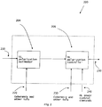
- Fig 1 shows a schematic block diagram of an apparatus 100 of the invention.
- the apparatus 100 is equipped with at least a first antenna 110 of a first polarization, and a second antenna 120 of a second polarization, the antennas 110 and 120 typically being implemented as a dual polarized antenna.
- these two polarizations are horizontal and vertical, respectively, as shown in fig 1 , although it is perfectly possible to use other combinations of polarizations, which need not be orthogonal with respect to each other but must not be identical.
- the apparatus additionally comprises a receiver block 130 and a transmitter block 140, each block containing one or more radio chains.
- the apparatus 100 is intended for communication with at least one other device in a wireless telecommunications system, such as a cellular telephony system.
- the apparatus 100 is also equipped with means 150 for measuring the polarization state of a signal which is received from said one other device, and with means 160 for adapting or controlling the polarization state of signals transmitted from the apparatus to the one other device on the basis of said measurement of the received signal.
- Said measuring and polarization control means 150, 160 can be one and the same functional block in the apparatus 100, as shown in fig 1 , or they can be separate function blocks or separate physical entities in the apparatus 100.
- the function of the measuring 150 and polarization control means 160 is to adapt the polarization of the signals which are to be transmitted from the apparatus 100 by the transmitter 140 to a polarization state which will improve the communications quality.
- the adaptation is carried out by means of applying weights or weight factors to the individual signals which are transmitted by the transmitter 130 from the first and second antennas.
- the weight factors can be pure phase factors, or they can comprise an amplitude factor as well, to change the relative signal amplitudes.
- replicas of a signal which is to be transmitted by the transmitter 140 of the device 100 by means of the antennas of the first 110 and second 120 polarizations will in the polarization control means 160 be given different phase and amplitude weights before it reaches the antennas, which will cause the signal transmitted by the antennas to have a resulting desired total polarization, for example a polarization which coincides with the polarization measured on the UL.
- the weights used for the transmitted signals are adapted to utilize the system in a way that is optimal in a desired sense, for example with respect to output power, and the polarization control may use different types of inputs.
- the goal of the polarization control is to optimize the polarization for DL transmission.
- the polarization control process for the DL transmission may be based on criteria other than replicating the UL polarization state, for example minimization of the DL transmission power for each UE individually, or per cell in a cellular telephony system. In such cases, the polarization state on the DL will not necessarily be identical to the one on the UL.
- Fig 2 shows a generic polarization controller 200 for use in a transmitter of the invention, which can be used to obtain the functions of the units 150 and 160 described previously and shown in fig 1 .
- the polarization controller 200 delivers as its output 250 the mentioned weight factor or factors to be used on the signals which are to be transmitted.
- the polarization controller 200 consists of two main functional blocks. In a first block 204, the UL polarization estimator, the UL polarization state is estimated or measured, and in a second block 206, DL polarization controller, the weights for DL transmission are calculated.
- One parameter for use by the polarization controller 200 is the mentioned UL measurements, which are shown as an input 210 to the controller unit 200.
- measurements are suitably carried out by a calibration function in the RBS.
- the polarization state of the received signal is observed by the polarization estimator 204 and input to DL polarization controller 206.
- Both the polarization estimator 204 and the DL polarization controller 206 take the known RBS amplitude, phase, and time delay characteristics into account.
- the DL polarization controller 206 of fig 2 can have other inputs than UL channel measurements, such as DL power control commands.
- the DL polarization controller 206 Since the phase characteristics of the base station are not known, the DL polarization controller 206 must have other inputs than UL channel measurements, such as DL power control commands etc, in order to support a search for the phase values which will produce the best polarization state, according to desired criteria such as transmit power, on DL.
- N the number of polarizations used on both UL and DL
- the DL polarization controller 206 monitors the system performance and adjusts the phase shifts to adapt to time-variations in the propagation channel.
- the adaptation process can be seen as corresponding to a search for the best polarization along a line, corresponding to constant relative amplitude, on the surface of a sphere, the so called Poincaré sphere shown in fig 3 .
- the search for the best polarization state may also encompass different values on the amplitude relations between the signals in the respective polarizations.
- the DL polarization controller 206 Since the amplitude characteristics of the base station are not known, the DL polarization controller 206 must have other inputs than UL channel measurements, such as DL power control commands etc, in order to support a search for the amplitude values which will produce the best polarization state, according to desired criteria such as transmit power, on DL.
- N the number of polarizations used on both UL and DL
- the DL polarization controller 206 monitors the system performance and adjusts the amplitude relations to adapt to time-variations in the propagation channel.
- the adaptation process can be seen as corresponding to a search for the best polarization along a line, corresponding to constant relative phase, on the surface of a sphere, the so called Poincaré sphere shown in fig 3 .
- the search for the best polarization state may also encompass different values on the phase differences between the signals in the respective polarizations.
- the base-station is neither amplitude nor phase coherent, meaning that the polarization state observed by the polarization estimator 204 will typically not be a correct estimate of the actual polarization state.
- the estimator still provides useful information such as arbitrary order derivatives of the estimator observables.
- the base station is non coherent, channel reciprocity can still be exploited.
- the polarization adaptation process encompasses a search, block 450, for polarization weights that are optimal in a desired sense, for example with respect to output power, the search being performed in a multidimensional space, i.e. with more than one parameter to be varied.
- the adaptation process is supported by for example DL power control commands from the UE and derivatives of observables from the polarization estimator 204, to continuously strive for the best possible DL weights.
- the adaptation process can be seen as corresponding to a search for the best polarization along two orthogonal directions on the surface of a sphere, the so called Poincaré sphere shown in fig 3 .
- the size of the search area on the Poincaré sphere, as well as the DL polarization controller 206 update rate, are both based on for example DL power control commands from the UE and derivatives of observables from the polarization estimator 204.
- This case is applicable for example when the channel is un-correlated between UL and DL or when there is a desire to have a low-complexity solution.
- a polarization controller 200 as shown in fig 2 should be used.
- the adaptation process may use different types of inputs. For example, if the input is only which of the polarization states (horizontal or vertical), has the highest power on the UL, the goal will typically be to use that polarization state for the DL transmission.
- the simplified principle for time-varying polarization control may be used in the following way: For arbitrarily dual polarized antennas, transform the received UL signals into a vertical and a horizontal polarization state, and estimate the average received power in the respective states. Select the polarization (horizontal or vertical) with the highest average UL power for DL transmission.
- the simplified principle for time-varying polarization control may instead be used in the following way: For dual polarized antennas with vertical and horizontal polarization states, estimate the average received power in the respective states. Select the polarization with the highest average UL power for DL transmission.
- the polarization adaptation process for the DL transmission may be based on criteria other than minimization of the DL transmission power on a UE-by-UE basis or per cell. Other criteria can for example be based on SINR, Signal to Interference Noise Ratio.
Abstract
Description
- The present invention relates to an apparatus in a wireless telecommunications system, the apparatus being intended for communication with at least one other device in the wireless telecommunications system. The apparatus comprises a receiver and a transmitter, and at least a first antenna of a first polarization and a second antenna of a second polarization.
- In current systems for wireless telecommunications, such as cellular telephony, the transmitters of the system, particularly those in the base stations, may be equipped with dual polarized antennas. Usually, this is in order to utilize the polarization of the radio channel for polarization reception diversity, as a complement to, or instead of, spatial diversity in the base station.
- Transmission is normally carried out on one of the antennas of the device, i.e. in this example the base station, but polarization transmission diversity where both antennas are used, also exists. In some cases, both antennas in the base station are used for transmission, with half (or some other proportion) of the signals being transmitted via one antenna, and the rest via the other. One purpose of such a transmission arrangement is to reduce combining losses which may occur when radio channels are combined in the base station after power amplification.
- Transmission diversity schemes such as the closed loop TX diversity in WCDMA can be seen as beam steering based on feedback when antennas with identical, or nearly identical, polarization are used. When antennas with orthogonal, or nearly orthogonal, polarization are used, closed loop TX diversity can instead be seen as a polarization adaptation. Instead of feedback information, uplink measurements can be used for adaptation of the downlink transmission.
- For example, in the case of beam steering, using an array antenna with multiple closely spaced identical radiating elements, downlink beam forming can be controlled based on uplink direction-of-arrival estimates.
- The purpose of the present invention is to utilize information regarding the polarization properties of the radio channel, including those of the receiving antennas, to improve the performance of the radio connection.
- This purpose is achieved by the present invention in that it discloses an apparatus in a wireless telecommunications system, which comprises at least a first antenna of a first polarization and a second antenna of a second polarization, as well as a receiver block and a transmitter block.
- The apparatus is intended for communication with at least one other device in the wireless telecommunications system, and is equipped with means for estimating the polarization state of a signal which is received from the one other device.
- The apparatus additionally comprises control means for adapting the polarization state of signals transmitted from the apparatus to the one other device on the basis of said measurement of the received signal and on available auxiliary information such as information extracted from control signalling and system performance measures.
- Thus, by means of the apparatus of the invention, the polarization properties of the radio channel may be utilized in order to improve the transmission quality of the radio connection.
- The invention will be described in more detail in the following, with reference to the appended drawings, in which
-
Fig 1 shows a polarization controller for use in the present invention, and -
Fig 2 shows a generic polarization controller, and -
Fig 3 shows a so called Poincaré sphere, for use in a version of the invention, and -
Fig 4 shows a schematic flowchart for carrying out the invention. - The invention will in the following description be explained with reference to a cellular telephony system, as a consequence of which the communication which will be described will be that between a radio base station, RBS, and a terminal, UE (user equipment), the RBS utilizing two antenna ports corresponding to two antennas with different polarizations.
- However, those skilled in the field will realize that this is only an example; the invention can be applied to a vast number of communication applications s, for example communication between an RBS and a repeater or relay node. Further, more than two antennas with different polarizations may be utilized at one or both ends of the communication system. Also, it should be pointed out that either end of the communication, i.e. either the RBS and/or the UE can be equipped with a device according to the invention. Naturally, both ends of the communication can also be equipped with such a device.
- With renewed reference to the cellular telephony system in the examples which will be used, the term Up Link (UL) will be used to refer to the communication from the UE to the RBS, and the term Down Link, (DL) will be used to refer to the communication from the RBS to the UE .
- Unless otherwise noted, the UE is assumed to use identical polarization states for reception and transmission. In general, however, arbitrary polarization states may be used by the UE, since auxiliary polarization control information, such as DL power control commands, is available to the RBS.
- Although the invention is described in detail for a wireless communication link between two entities, an RBS and a UE, it should be understood that the invention also applies to systems with an arbitrary number of communication links between an RBS and a UE, for example as in a MIMO system, in which the invention may be applied to for example each stream of information.
-
Fig 1 shows a schematic block diagram of anapparatus 100 of the invention. In anapparatus 100 of the invention, it is assumed that theapparatus 100 is equipped with at least afirst antenna 110 of a first polarization, and asecond antenna 120 of a second polarization, theantennas fig 1 , although it is perfectly possible to use other combinations of polarizations, which need not be orthogonal with respect to each other but must not be identical. - In addition to said
antennas receiver block 130 and atransmitter block 140, each block containing one or more radio chains. Theapparatus 100 is intended for communication with at least one other device in a wireless telecommunications system, such as a cellular telephony system. - The
apparatus 100 is also equipped withmeans 150 for measuring the polarization state of a signal which is received from said one other device, and withmeans 160 for adapting or controlling the polarization state of signals transmitted from the apparatus to the one other device on the basis of said measurement of the received signal. Said measuring and polarization control means 150, 160 can be one and the same functional block in theapparatus 100, as shown infig 1 , or they can be separate function blocks or separate physical entities in theapparatus 100. - The function of the measuring 150 and polarization control means 160 is to adapt the polarization of the signals which are to be transmitted from the
apparatus 100 by thetransmitter 140 to a polarization state which will improve the communications quality. - The adaptation is carried out by means of applying weights or weight factors to the individual signals which are transmitted by the
transmitter 130 from the first and second antennas. The weight factors can be pure phase factors, or they can comprise an amplitude factor as well, to change the relative signal amplitudes. Thus, replicas of a signal which is to be transmitted by thetransmitter 140 of thedevice 100 by means of the antennas of the first 110 and second 120 polarizations will in the polarization control means 160 be given different phase and amplitude weights before it reaches the antennas, which will cause the signal transmitted by the antennas to have a resulting desired total polarization, for example a polarization which coincides with the polarization measured on the UL. - The weights used for the transmitted signals are adapted to utilize the system in a way that is optimal in a desired sense, for example with respect to output power,, and the polarization control may use different types of inputs. In the case described above, where the only input is the polarization state on the UL-signal, the goal of the polarization control is to optimize the polarization for DL transmission.
- If and when further inputs are available, as will be described in more detail in the following, the polarization control process for the DL transmission may be based on criteria other than replicating the UL polarization state, for example minimization of the DL transmission power for each UE individually, or per cell in a cellular telephony system. In such cases, the polarization state on the DL will not necessarily be identical to the one on the UL.
-
Fig 2 shows ageneric polarization controller 200 for use in a transmitter of the invention, which can be used to obtain the functions of theunits fig 1 . Thepolarization controller 200 delivers as itsoutput 250 the mentioned weight factor or factors to be used on the signals which are to be transmitted. Thepolarization controller 200 consists of two main functional blocks. In afirst block 204, the UL polarization estimator, the UL polarization state is estimated or measured, and in asecond block 206, DL polarization controller, the weights for DL transmission are calculated. - One parameter for use by the
polarization controller 200 is the mentioned UL measurements, which are shown as aninput 210 to thecontroller unit 200. - Apart from the
UL channel measurements 210, other parameters for input to thepolarization controller 200 can be: - UL base station coherency information, such as phase and amplitude properties of the RBS on reception. This is an
input 220 to theUL polarization estimator 204. - DL base station coherency information, in other words such as phase and amplitude properties of the RBS on transmission. This is an
input 230 to theDL polarization controller 206. - DL power control commands, i.e. power commands from the one other device to the RBS. This is an
input 240 to theDL polarization controller 206. - Information regarding the antenna configuration at the UE. Examples of such information can be whether the same antenna is used for reception and transmission and also the number of antennas used for reception if more than one.
- In order to find the UL and DL base station coherency information, measurements are suitably carried out by a calibration function in the RBS.
- All of the parameters listed above need to be taken into account by the
polarization controller 200 offig 2 in order to achieve a good polarization adaptation of the transmitted signal. - A number of cases can be discerned when it comes to the information which is available to the
polarization controller 200, and the steps to be taken by the controller as a consequence of this information. These cases will be described in the following, using the definitions given below: - Channel: This term is in the following taken to mean the characteristics of the propagation paths between the apparatus of the invention and the one other device with which it communicates.
- Correlated channel: The amplitude and phase values of the polarization components are correlated over a sufficiently long time and over a sufficiently wide frequency band, so that channel measurements performed on the UL are valid for use on the DL.
- Power-correlated channel: The amplitude relation between the polarizations is correlated over a sufficiently long time and over a sufficiently wide frequency band, so that channel measurements performed on the UL are valid for use on the DL.
- Non-correlated channel: The channel polarization state measurements performed on the UL are not valid for use on the DL.
- Coherent base station: Amplitude, phase and time delay characteristics for the radio chains used for the UL are sufficiently known. Amplitude, phase and time delay characteristics for the radio chains used for the DL are sufficiently known.
- Amplitude coherent base station: Amplitude and time delay characteristics for the radio chains used for the UL are sufficiently known. Amplitude and time delay characteristics for the radio chains used for the DL are sufficiently known.
- Phase coherent base station: Phase and time delay characteristics for the radio chains used for the UL are sufficiently known. Phase and time delay characteristics for the radio chains used for the DL are sufficiently known.
- Non-coherent base station: Neither amplitude nor phase characteristics for the radio chains used for the UL are sufficiently known. Neither amplitude nor phase characteristics for the radio chains used for the DL are sufficiently known.
- Examples of cases in which the present invention can be applied are given below, as well as an explanation of how the present invention adapts to each of these cases. These cases are also briefly shown in the
flowchart 400 offig 4 , which is referred to below. - In this case, which corresponds to block 425 of
fig 4 , the polarization state of the received signal is observed by thepolarization estimator 204 and input toDL polarization controller 206. Both thepolarization estimator 204 and theDL polarization controller 206 take the known RBS amplitude, phase, and time delay characteristics into account. - The
DL polarization controller 206 offig 2 can have other inputs than UL channel measurements, such as DL power control commands. - In this case, which corresponds to block 435 of
fig 4 , due to the unknown phase relations between the polarizations, only the amplitude components in the polarization state observed by thepolarization estimator 204 can be used by theDL polarization controller 206. Both thepolarization estimator 204 and theDL polarization controller 206 take the known RBS amplitude and time delay characteristics into account. - Since the phase characteristics of the base station are not known, the
DL polarization controller 206 must have other inputs than UL channel measurements, such as DL power control commands etc, in order to support a search for the phase values which will produce the best polarization state, according to desired criteria such as transmit power, on DL. - The relative phase values can be found by a (N-1) dimensional search, where N is the number of polarizations used on both UL and DL, i.e. in the present example N = 2. In other words, the device of the invention will apply a number of different phase shifts between the two polarizations used to transmit the signals, and will observe for example the DL power control commands from the UE. The
DL polarization controller 206 monitors the system performance and adjusts the phase shifts to adapt to time-variations in the propagation channel. - In the case of a dual polarized antenna having orthogonal polarizations, the adaptation process can be seen as corresponding to a search for the best polarization along a line, corresponding to constant relative amplitude, on the surface of a sphere, the so called Poincaré sphere shown in
fig 3 . For fine-tuning, the search for the best polarization state may also encompass different values on the amplitude relations between the signals in the respective polarizations. - In this case, which corresponds to block 445 of
fig 4 , due to the unknown amplitude relations between the polarizations, only the phase components in the polarization state observed on the UL by thepolarization estimator 204 can be used by theDL polarization controller 206. Both thepolarization estimator 204 and theDL polarization controller 206 take the known RBS phase and time characteristics into account. - Since the amplitude characteristics of the base station are not known, the
DL polarization controller 206 must have other inputs than UL channel measurements, such as DL power control commands etc, in order to support a search for the amplitude values which will produce the best polarization state, according to desired criteria such as transmit power, on DL. - The relative amplitude values can be found by a (N-1)-dimensional search where N is the number of polarizations used on both UL and DL, i.e. in the present example, N = 2. In other words, the device of the invention will apply a number of different amplitude relations between the two polarizations used to transmit the signals, and will observe for example the DL power control commands from the UE. The
DL polarization controller 206 monitors the system performance and adjusts the amplitude relations to adapt to time-variations in the propagation channel. - In the case of a dual polarized antenna having orthogonal polarizations, the adaptation process can be seen as corresponding to a search for the best polarization along a line, corresponding to constant relative phase, on the surface of a sphere, the so called Poincaré sphere shown in
fig 3 . For fine-tuning, the search for the best polarization state may also encompass different values on the phase differences between the signals in the respective polarizations. - In this case, the base-station is neither amplitude nor phase coherent, meaning that the polarization state observed by the
polarization estimator 204 will typically not be a correct estimate of the actual polarization state. However, the estimator still provides useful information such as arbitrary order derivatives of the estimator observables. Thus, even though the base station is non coherent, channel reciprocity can still be exploited. - The polarization adaptation process encompasses a search, block 450, for polarization weights that are optimal in a desired sense, for example with respect to output power, the search being performed in a multidimensional space, i.e. with more than one parameter to be varied. The adaptation process is supported by for example DL power control commands from the UE and derivatives of observables from the
polarization estimator 204, to continuously strive for the best possible DL weights. - In the case of a dual polarized antenna having orthogonal polarizations, the adaptation process can be seen as corresponding to a search for the best polarization along two orthogonal directions on the surface of a sphere, the so called Poincaré sphere shown in
fig 3 . In other words, all relevant combinations of two orthogonally polarized signals will be tried in this case, The size of the search area on the Poincaré sphere, as well as theDL polarization controller 206 update rate, are both based on for example DL power control commands from the UE and derivatives of observables from thepolarization estimator 204. - A general observation can be made: The polarization state of radio waves transmitted with horizontal or vertical polarization, and only with these polarizations, is to a large extent maintained over many propagation channels. This leads to a simplified principle for time-varying polarization control: Perform DL transmission using either vertical or horizontal polarization, based on for example which of these polarizations has the highest mean power on the UL.
- This case is applicable for example when the channel is un-correlated between UL and DL or when there is a desire to have a low-complexity solution.
- Even in this simplified case, a
polarization controller 200 as shown infig 2 should be used. The adaptation process may use different types of inputs. For example, if the input is only which of the polarization states (horizontal or vertical), has the highest power on the UL, the goal will typically be to use that polarization state for the DL transmission. - In a coherent base station, the simplified principle for time-varying polarization control may be used in the following way: For arbitrarily dual polarized antennas, transform the received UL signals into a vertical and a horizontal polarization state, and estimate the average received power in the respective states. Select the polarization (horizontal or vertical) with the highest average UL power for DL transmission.
- In a base station which is only amplitude coherent, the simplified principle for time-varying polarization control may instead be used in the following way: For dual polarized antennas with vertical and horizontal polarization states, estimate the average received power in the respective states. Select the polarization with the highest average UL power for DL transmission.
- If further inputs are available, the polarization adaptation process for the DL transmission may be based on criteria other than minimization of the DL transmission power on a UE-by-UE basis or per cell. Other criteria can for example be based on SINR, Signal to Interference Noise Ratio.
Claims (17)
- An apparatus (100) in a wireless telecommunications system, said apparatus (100) comprising at least a first antenna (110) of a first polarization and a second antenna (120) of a second polarization, the apparatus (100) additionally comprising a receiver block (130) and a transmitter block (140), the apparatus (100) being intended for communication with at least one other device in the wireless telecommunications system, characterized in that the apparatus (100) is equipped with means (150, 204) for estimating the polarization state of a signal which is received from the one other device, and in that the apparatus (100) additionally comprises control means (160, 206) for adapting the polarization state of a signal transmitted from the apparatus (100) to the one other device on the basis of said measurement of the received signal.
- The device (100) of claim 1, in which the adapted polarization state of the transmitted signal is obtained by means of applying weight factors to the replicas of the signal which are transmitted from the first (110) and second (120) antennas respectively.
- The device (100) of claim 2, in which a means (200) for polarization adaptation comprises two function blocks, one (204) for uplink polarization estimation and one (206) for downlink polarization control.
- The device (100) of any of claims 1-3, in which the means for uplink polarization estimation (204) comprises input means for other parameters than uplink estimates.
- The device of claim 4, in which said other parameters include information on phase coherency and irregularities in the receiving apparatus.
- The device of any of claims 1-5, in which the means (160, 206) for controlling the polarization state of a signal transmitted from the apparatus (100) comprises inputs from the means (150, 204) for estimating the polarization state of a received signal.
- The device of claim 6, in which the means (160, 206) for controlling the polarization state of a signal transmitted from the apparatus (100) also comprises inputs (230, 240) for other parameters than those received from the means (150, 204) for measuring the polarization state of a received signal.
- The device of claim 7, in which said other parameters include information on phase coherency and irregularities in the device (100) on transmission, and/or power control commands from the one other device to the device (100).
- A method for use in an apparatus in a wireless telecommunications system, in which apparatus there is at least a first antenna (110) of a first polarization and a second antenna (120) of a second polarization, there also being a receiver block (130) and a transmitter block (140) in the apparatus, the method being intended for use when the apparatus (100) communicates with at least one other device in the wireless telecommunications system, characterized in that it comprises the following:- estimating the polarization state of a signal which is received in the apparatus (100) from the one other device,- adapting the polarization state of a signal transmitted from the apparatus (100) to the one other device on the basis of said measurement of the received signal.
- The method of claim 9, in which the polarization adaptation of a transmitted signal is obtained by means of applying weight factors to the signal replicas which are transmitted from the first (110) and second (120) antennas of the apparatus (100) respectively.
- The method of claim 9 or 10, in which the uplink polarization estimation (204) comprises other input parameters than uplink estimates.
- The method of claim 11, in which said other parameters include information on phase coherency and irregularities in the receiver of the apparatus (100).
- The method of any of claims 9-12, in which, if the phase characteristics of the apparatus (100) are not known, a search is performed for the phase values which will produce the best polarization state for the transmitted signal.
- The method of any of claims 9-12, in which, if the amplitude characteristics of the apparatus (100) are not known, a search is performed for the amplitude values which will produce the best polarization state for the transmitted signal.
- The method of any of claims 9-12, in which, if neither the amplitude nor the phase characteristics of the apparatus (100) are known, a search is performed for the combination of amplitude and phase values which will produce the best polarization state for the transmitted signal.
- The method of any of claims 13-15, in which the search is performed using downlink power control commands.
- The method of claim 9 or 10, in which the polarization adaptation is carried out by estimating the average received power in the respective first and second antennas, and select the antenna with the highest average power for transmission by the apparatus (100).
Priority Applications (1)
| Application Number | Priority Date | Filing Date | Title |
|---|---|---|---|
| EP16158666.4A EP3043490A1 (en) | 2006-07-06 | 2006-07-06 | A device for improved isolation characteristics in a telecommunications system |
Applications Claiming Priority (3)
| Application Number | Priority Date | Filing Date | Title |
|---|---|---|---|
| EP16158666.4A EP3043490A1 (en) | 2006-07-06 | 2006-07-06 | A device for improved isolation characteristics in a telecommunications system |
| EP06777611.2A EP2050206B1 (en) | 2006-07-06 | 2006-07-06 | A device for improved isolation characteristics in a telecommunications system |
| PCT/EP2006/063962 WO2008003354A1 (en) | 2006-07-06 | 2006-07-06 | A device for improved isolation characteristics in a telecommunications system |
Related Parent Applications (2)
| Application Number | Title | Priority Date | Filing Date |
|---|---|---|---|
| EP06777611.2A Division EP2050206B1 (en) | 2006-07-06 | 2006-07-06 | A device for improved isolation characteristics in a telecommunications system |
| EP06777611.2A Division-Into EP2050206B1 (en) | 2006-07-06 | 2006-07-06 | A device for improved isolation characteristics in a telecommunications system |
Publications (1)
| Publication Number | Publication Date |
|---|---|
| EP3043490A1 true EP3043490A1 (en) | 2016-07-13 |
Family
ID=37839201
Family Applications (2)
| Application Number | Title | Priority Date | Filing Date |
|---|---|---|---|
| EP06777611.2A Not-in-force EP2050206B1 (en) | 2006-07-06 | 2006-07-06 | A device for improved isolation characteristics in a telecommunications system |
| EP16158666.4A Withdrawn EP3043490A1 (en) | 2006-07-06 | 2006-07-06 | A device for improved isolation characteristics in a telecommunications system |
Family Applications Before (1)
| Application Number | Title | Priority Date | Filing Date |
|---|---|---|---|
| EP06777611.2A Not-in-force EP2050206B1 (en) | 2006-07-06 | 2006-07-06 | A device for improved isolation characteristics in a telecommunications system |
Country Status (6)
| Country | Link |
|---|---|
| US (1) | US8295772B2 (en) |
| EP (2) | EP2050206B1 (en) |
| CN (1) | CN101479959A (en) |
| ES (1) | ES2587340T3 (en) |
| PT (1) | PT2050206T (en) |
| WO (1) | WO2008003354A1 (en) |
Families Citing this family (12)
| Publication number | Priority date | Publication date | Assignee | Title |
|---|---|---|---|---|
| GB0700801D0 (en) | 2007-01-16 | 2007-02-21 | Nortel Networks Ltd | Shared radio backhaul system |
| US8605703B2 (en) * | 2007-01-30 | 2013-12-10 | Georgia Tech Research Corporation | Methods for polarization-based interference mitigation |
| US9270359B2 (en) * | 2010-10-05 | 2016-02-23 | Telefonaktiebolaget L M Ericsson (Publ) | Method and arrangement for polarization control in a communication system |
| US20140225805A1 (en) * | 2011-03-15 | 2014-08-14 | Helen K. Pan | Conformal phased array antenna with integrated transceiver |
| US8954023B2 (en) * | 2011-06-24 | 2015-02-10 | Lhc2 Inc | Adaptive polarization array (APA) |
| US8976713B2 (en) * | 2011-08-02 | 2015-03-10 | Electronics And Telecommunications Research Institute | Method and apparatus for performing transmission and reception simultaneously in same frequency band |
| US9258051B2 (en) | 2012-06-11 | 2016-02-09 | Lhc2 Inc | Optimization of transmit signal polarization of an adaptive polarization array (APA) |
| US9312944B2 (en) | 2013-12-26 | 2016-04-12 | Aruba Networks, Inc. | System, apparatus and method for integrated wireless link management for a multi-polarized antenna system |
| CN105335615B (en) * | 2015-10-31 | 2018-09-21 | 电子科技大学 | A kind of two dimension angular and polarization parameter combined estimation method of low complex degree |
| CN109450505B (en) * | 2016-05-13 | 2019-11-15 | 华为技术有限公司 | A kind of channel information sending method, data transmission method for uplink and equipment |
| US10848207B2 (en) * | 2019-03-01 | 2020-11-24 | Carlos A. Rios | Methods and apparatus for orthogonal stream spatial multiplexing |
| US11025311B1 (en) | 2020-08-28 | 2021-06-01 | Carlos A. Rios | Methods and apparatus for orthogonal stream spatial multiplexing and beamforming |
Citations (3)
| Publication number | Priority date | Publication date | Assignee | Title |
|---|---|---|---|---|
| WO2001054230A1 (en) * | 2000-01-21 | 2001-07-26 | Motorola Inc. | System and method for wireless communication using polarization diversity |
| US20030092402A1 (en) * | 2000-01-27 | 2003-05-15 | Joseph Shapira | System and method for providing polarization matching on a cellular communication forward link |
| WO2004015887A1 (en) * | 2002-08-05 | 2004-02-19 | Nokia Corporation | Transmission diversity with two cross-polarised antennas arrays |
Family Cites Families (1)
| Publication number | Priority date | Publication date | Assignee | Title |
|---|---|---|---|---|
| AU2001232166A1 (en) * | 2000-01-27 | 2001-08-07 | Celletra Ltd. | System and method for providing polarization matching on a cellular communication forward link |
-
2006
- 2006-07-06 EP EP06777611.2A patent/EP2050206B1/en not_active Not-in-force
- 2006-07-06 WO PCT/EP2006/063962 patent/WO2008003354A1/en active Application Filing
- 2006-07-06 CN CNA2006800552477A patent/CN101479959A/en active Pending
- 2006-07-06 US US12/307,660 patent/US8295772B2/en active Active
- 2006-07-06 ES ES06777611.2T patent/ES2587340T3/en active Active
- 2006-07-06 PT PT67776112T patent/PT2050206T/en unknown
- 2006-07-06 EP EP16158666.4A patent/EP3043490A1/en not_active Withdrawn
Patent Citations (3)
| Publication number | Priority date | Publication date | Assignee | Title |
|---|---|---|---|---|
| WO2001054230A1 (en) * | 2000-01-21 | 2001-07-26 | Motorola Inc. | System and method for wireless communication using polarization diversity |
| US20030092402A1 (en) * | 2000-01-27 | 2003-05-15 | Joseph Shapira | System and method for providing polarization matching on a cellular communication forward link |
| WO2004015887A1 (en) * | 2002-08-05 | 2004-02-19 | Nokia Corporation | Transmission diversity with two cross-polarised antennas arrays |
Non-Patent Citations (2)
| Title |
|---|
| MILLER S ET AL: "TRANSMISSION CONSIDERATIONS FOR POLARIZATION-SMART ANTENNAS", VTC 2001 SPRING. IEEE VTS 53RD. VEHICULAR TECHNOLOGY CONFERENCE. RHODES, GREECE, MAY 6 - 9, 2001, IEEE VEHICULAR TECHNOLGY CONFERENCE, NEW YORK, NY : IEEE, US, vol. VOL. 1 OF 4. CONF. 53, 6 May 2001 (2001-05-06), pages 258 - 262, XP001066961, ISBN: 0-7803-6728-6 * |
| SHAPIRA J ET AL: "A NOVEL POLARIZATION SMART ANTENNA", VTC 2001 SPRING. IEEE VTS 53RD. VEHICULAR TECHNOLOGY CONFERENCE. RHODES, GREECE, MAY 6 - 9, 2001, IEEE VEHICULAR TECHNOLGY CONFERENCE, NEW YORK, NY : IEEE, US, vol. VOL. 1 OF 4. CONF. 53, 6 May 2001 (2001-05-06), pages 253 - 257, XP001066960, ISBN: 0-7803-6728-6 * |
Also Published As
| Publication number | Publication date |
|---|---|
| WO2008003354A1 (en) | 2008-01-10 |
| PT2050206T (en) | 2016-07-11 |
| CN101479959A (en) | 2009-07-08 |
| EP2050206B1 (en) | 2016-05-18 |
| EP2050206A1 (en) | 2009-04-22 |
| ES2587340T3 (en) | 2016-10-24 |
| US20090197544A1 (en) | 2009-08-06 |
| US8295772B2 (en) | 2012-10-23 |
Similar Documents
| Publication | Publication Date | Title |
|---|---|---|
| US8295772B2 (en) | Device for improved isolation characteristics in a telecommunications system | |
| US9294259B2 (en) | Full duplex system in massive MIMO | |
| EP3114781B1 (en) | Antenna array self-calibration | |
| EP2923450B1 (en) | Apparatus and method for beamforming gain difference compensation according to change of transmitting and receiving beam pattern in beamforming based wireless communication system | |
| KR102066645B1 (en) | Uplink training for mimo implicit beamforming | |
| EP2932622B1 (en) | Antenna reconfiguration for mimo communications when multiplicative noise limited | |
| US20120100813A1 (en) | System for testing multi-antenna devices using bidirectional faded channels | |
| CN107211484B (en) | Symmetric and full duplex repeaters in wireless systems | |
| WO2007062491A1 (en) | Device and method for calibrating mimo systems | |
| EP1700438A1 (en) | Calibration method to achieve reciprocity of bidirectional communication channels | |
| JP5923221B2 (en) | Transmission power distribution for MIMO communications when limited by multiplicative noise | |
| KR20150052482A (en) | Method and apparatus for beam training in communication system | |
| CA2660103A1 (en) | Repeater having dual receiver or transmitter antenna configuration with adaptation for increased isolation | |
| EP1551143A1 (en) | Calibration method to achieve reciprocity of bidirectional communication channels | |
| US9154204B2 (en) | Implementing transmit RDN architectures in uplink MIMO systems | |
| Liu et al. | A novel and low-cost analog front-end mismatch calibration scheme for MIMO-OFDM WLANs | |
| CN107483125B (en) | Data processing method and system based on LTE/LTE upgrade version cell | |
| WO2003026161A1 (en) | Adaptive transceiver system | |
| US9531447B2 (en) | Collaborative channel sounding in multi-antenna systems | |
| WO2019214985A1 (en) | Methods and devices for polarization optimization of mimo wireless transmission | |
| CN102547953A (en) | Method for obtaining beam forming gain | |
| US11689299B2 (en) | Wireless communication apparatus with calibration | |
| CN105790821A (en) | Equipment for improved isolation characteristic in telecommunication system | |
| CN113825242B (en) | Antenna calibration position self-adaptive adjustment method and device | |
| Timoshenko et al. | 5G Base Station Prototyping: Massive MIMO Approaches |
Legal Events
| Date | Code | Title | Description |
|---|---|---|---|
| PUAI | Public reference made under article 153(3) epc to a published international application that has entered the european phase |
Free format text: ORIGINAL CODE: 0009012 |
|
| 17P | Request for examination filed |
Effective date: 20160304 |
|
| AC | Divisional application: reference to earlier application |
Ref document number: 2050206 Country of ref document: EP Kind code of ref document: P |
|
| AK | Designated contracting states |
Kind code of ref document: A1 Designated state(s): AT BE BG CH CY CZ DE DK EE ES FI FR GB GR HU IE IS IT LI LT LU LV MC NL PL PT RO SE SI SK TR |
|
| STAA | Information on the status of an ep patent application or granted ep patent |
Free format text: STATUS: REQUEST FOR EXAMINATION WAS MADE |
|
| STAA | Information on the status of an ep patent application or granted ep patent |
Free format text: STATUS: THE APPLICATION IS DEEMED TO BE WITHDRAWN |
|
| 18D | Application deemed to be withdrawn |
Effective date: 20170114 |