EP3043365B1 - Verfahren und Steuerungssystem zur Steuerung einer Schaltvorrichtung - Google Patents
Verfahren und Steuerungssystem zur Steuerung einer Schaltvorrichtung Download PDFInfo
- Publication number
- EP3043365B1 EP3043365B1 EP15150502.1A EP15150502A EP3043365B1 EP 3043365 B1 EP3043365 B1 EP 3043365B1 EP 15150502 A EP15150502 A EP 15150502A EP 3043365 B1 EP3043365 B1 EP 3043365B1
- Authority
- EP
- European Patent Office
- Prior art keywords
- contacts
- couple
- time
- predetermined
- actuation
- Prior art date
- Legal status (The legal status is an assumption and is not a legal conclusion. Google has not performed a legal analysis and makes no representation as to the accuracy of the status listed.)
- Active
Links
- 238000000034 method Methods 0.000 title claims description 83
- 238000001514 detection method Methods 0.000 claims description 25
- 239000004065 semiconductor Substances 0.000 claims description 12
- 238000005259 measurement Methods 0.000 claims description 5
- 230000004048 modification Effects 0.000 claims description 4
- 238000012986 modification Methods 0.000 claims description 4
- FGUUSXIOTUKUDN-IBGZPJMESA-N C1(=CC=CC=C1)N1C2=C(NC([C@H](C1)NC=1OC(=NN=1)C1=CC=CC=C1)=O)C=CC=C2 Chemical compound C1(=CC=CC=C1)N1C2=C(NC([C@H](C1)NC=1OC(=NN=1)C1=CC=CC=C1)=O)C=CC=C2 FGUUSXIOTUKUDN-IBGZPJMESA-N 0.000 claims 2
- 238000000926 separation method Methods 0.000 description 15
- 230000008878 coupling Effects 0.000 description 5
- 238000010168 coupling process Methods 0.000 description 5
- 238000005859 coupling reaction Methods 0.000 description 5
- 230000000694 effects Effects 0.000 description 3
- 238000013461 design Methods 0.000 description 2
- 238000010586 diagram Methods 0.000 description 2
- 230000009467 reduction Effects 0.000 description 2
- 238000012360 testing method Methods 0.000 description 2
- 230000000903 blocking effect Effects 0.000 description 1
- 239000000463 material Substances 0.000 description 1
- 230000003287 optical effect Effects 0.000 description 1
- 238000009666 routine test Methods 0.000 description 1
- 230000001052 transient effect Effects 0.000 description 1
Images


Classifications
-
- H—ELECTRICITY
- H01—ELECTRIC ELEMENTS
- H01H—ELECTRIC SWITCHES; RELAYS; SELECTORS; EMERGENCY PROTECTIVE DEVICES
- H01H9/00—Details of switching devices, not covered by groups H01H1/00 - H01H7/00
- H01H9/54—Circuit arrangements not adapted to a particular application of the switching device and for which no provision exists elsewhere
- H01H9/56—Circuit arrangements not adapted to a particular application of the switching device and for which no provision exists elsewhere for ensuring operation of the switch at a predetermined point in the AC cycle
-
- H—ELECTRICITY
- H01—ELECTRIC ELEMENTS
- H01H—ELECTRIC SWITCHES; RELAYS; SELECTORS; EMERGENCY PROTECTIVE DEVICES
- H01H7/00—Devices for introducing a predetermined time delay between the initiation of the switching operation and the opening or closing of the contacts
- H01H7/16—Devices for ensuring operation of the switch at a predetermined point in the AC cycle
Definitions
- the present invention relates to a method for controlling a switching device, in particular for synchronizing actuations of the switching device to a reference electrical signal; the present invention also relates to a control system adapted to carry out such method.
- a switching device is a device conceived for connecting/disconnecting two parts of an electrical circuit into which it is installed.
- the switching device comprises one or more electrical phases, each one having at least one couple of contacts which can be switched between a closed condition, where the contacts are coupled to each other, and an open condition, where the contacts are separated from each other.
- a control system can be provided for controlling the operations of the switching device, in such a way to synchronize the switching of the contacts to a reference waveform of an electrical signal associated to the electrical circuit into which the switching device itself is installed.
- control system comprises control means which are adapted to operate by using a sequence of time cycles.
- the time cycles are set with a predetermined time duration.
- the control means are adapted to control the actuation of the couple of contacts by using the time cycles with the predetermined time duration.
- the aim of this control is switching the contacts at a corresponding predetermined electrical angle of the reference waveform.
- This predetermined electrical angle can be suitably chosen to avoid, or at least reduce, the generation of electrical arcs, inrush currents and transient voltages during the operation of the switching device.
- control means are adapted to execute the above mentioned control while assuming nominal values of relevant electrical and/or mechanical parameters which are associated to the phase and which could condition the desired synchronization of the contact switchings with the reference waveform.
- control means would fail to keep the desired synchronization as better illustrated with reference to an exemplary known switching device.
- An exemplary known switching device comprises, for each electrical phase, two couples of contacts which are operatively associated to at least one semiconductor device.
- the two couples of contacts must be switched in sequence at predetermined electrical angles of the reference waveform, in such a way to correctly use the semiconductor device for the switching tasks.
- the two couples of contacts are realized by a common movable contact and two corresponding fixed contacts spatially separated from each other.
- the movable contact can be actuated between a full-open position, where it is separated from both the first and second fixed contacts, and a closed position where it is coupled to the first fixed contact.
- the second fixed contact is disposed between the first fixed contact and the movable contact in the full-open position, so as to be connected with the movable contact during a portion of its travel path between the first and second fixed contacts.
- the control means are set to control the actuation of the movable contact using the time cycles with the predetermined time duration, in such a way that:
- control means are set to execute the above control while assuming a frequency value of the reference waveform equal to the frequency nominal value of the electric circuit.
- control means are adapted to apply a delay time between a detection of a predetermined reference point of the waveform and a predetermined starting point of the actuation of the movable contact.
- This delay time is set according to the nominal frequency value and, hence, if the real frequency value does not correspond to such nominal value, the starting of the actuation of the movable contact will occur too early or too late with respect to the predetermined starting point.
- control means are set to control the actuation of the movable contact while assuming a first preset time interval between the first and second predetermined points, and a second preset time interval between the third and fourth predetermined points of the reference waveform.
- These first and second preset time intervals are based on the nominal frequency value.
- a value difference between the real and nominal frequencies means a stretching or a reduction of the real time interval between the first and second predetermined points with respect to the first preset time interval, and a stretching or a reduction of the real time interval between the third and fourth predetermined points with respect to the second preset time interval.
- control means are set to execute the control of the movable contact while assuming a distance between the first and second fixed contacts having a value corresponding to a nominal value devised in the design of the switching device.
- the real value of such distance can vary in each single realized switching device with respect to the nominal designed value, due for example to mechanical tolerances.
- Document EP 2 068 335 A1 relates to a switching controlgear of circuit breaker which causes the circuit breaker to open or to close at a desired phase by delaying an output timing of an opening command signal or closing command signal to the circuit breaker, wherein the controller is adapted to operate by using time cycles with predetermined time duration.
- Another aspect of the present invention is to provide a switching device comprising a control system as defined by the annexed claims and disclosed in the following description.
- Another aspect of the preset invention is to provide a switchgear comprising a control system and/or a switching device according the annexed claims and disclosed in the following description. Further characteristics and advantages will become more apparent from the description of some preferred but not exclusive embodiments of the control system, control method and related switching device according to the invention, illustrated only by way of non-limiting examples with the aid of the accompanying drawings, wherein:
- any component as a whole, or to any part of a component, or to a whole combinations of components, or even to any part of a combination of components, it has to be understood that it means and encompasses correspondingly either the structure, and/or configuration and/or form and/or positioning of the related component or part thereof, or combinations of components or part thereof, such term refers to.
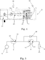
- the present disclosure is related to a method for controlling a switching device 1 and to a control system for carrying out such method; the control method and system are hereinafter globally indicated with numeral references 100 and 200, respectively.
- the method 100 is adapted to control a switching device 1 for connecting/disconnecting to/from each other two parts 5, 6 of an electric circuit into which the switching device 1 itself can be installed.
- the switching device 1 has at least one phase 2 which comprises at least one couple of contacts 3, 4. This at least one couple of contacts 3, 4 can be actuated for switching between a closed condition, where its contacts 10-12, 10-11 are coupled to each other, and an open condition, where its contacts 10-12, 10-11 are separated from each other.
- figures 2-4 show one phase 2 of the exemplary switching device 1.
- This phase 2 comprises terminals 20, 21 for connecting the phase 2 to a power supply 5 and to an associated load 6 of the electrical circuit.
- phase 2 comprises:
- the two couples of contacts 3, 4 are realized by a common movable contact 10 and two corresponding fixed contacts 11, 12 which are spatially separated from each other by a distance X.
- the movable contact 10 can be actuated, for example through a rotating motor 13, between a full-open position (illustrated in figure 2 ), where it is separated from both the fixed contacts 11 and 12, and a closed position where it is coupled to the fixed contact 11 (as illustrated in figure 6 ).
- the second fixed contact 12 is disposed between the fixed contact 11 and the movable contact 10 in the full-open position, so as to be connected with the movable contact 10 during a travel path thereof between the fixed contacts 11 and 12.
- the method 100 comprises the step 101 of providing control means 201 for controlling the actuation of the couples of contacts 3, 4 in the phases 2.
- control system 200 comprises such control means 201 which are adapted to operate using time cycles 300; in practice, the control means 201 are adapted to execute an operation at each time cycle 300.
- the time cycles 300 are initially set with a predetermined time duration T p , according to method step 102.
- the method 100 further comprises the step 103 of detecting a difference of a value of at least one parameter 150 associated to the phase 2 with respect to a preset value 500.
- control system 200 comprises means 202 for detecting the difference between the value of the parameter 150 and the preset value 500.
- the method 100 comprises a step 104, that is:
- This controlling is such that the switching between the open and closed positions of the at least one couple of contacts 3, 4 is controlled to occur at a predetermined electrical angle 351-354 of a waveform 350 of an electrical signal associated to the phase 2.
- the control means 201 are adapted to execute such method step 104.
- control means 201 are advantageously adapted to:
- the modification of the predetermined time duration T p is such that the switching of the at least one couple of contacts 3,4 is controlled to occur at the same predetermined electrical angle 351-354 of the waveform 350 at which such switching is controlled to occur by method step 104.
- control means 201 are set to control a predetermined synchronization between the switching of the at least one couple of contacts 3, 4 and the waveform 350, by using time cycles 300 with the initially set time duration T p and under the condition that the value of the parameter 150 corresponds to the preset value 500.
- a difference of the parameter 150 with respect to the preset value 500 can influence such predetermined synchronization; for example, the parameter 150 can be an electrical parameter of the waveform 350 or a mechanical parameter associated to the couple of contacts 3, 4.
- control means 201 are adapted to modify the initially set time duration T p , of the time cycles 300 so as to keep the desired predetermined synchronization between the switching of the at least one couple of contacts 3, 4 and the waveform 350, even if the actual value of the parameter 150 is not equal to the presumed preset value 500.
- the method step 103 comprises the following steps 107 and 108:
- a preferred but not limited way of carrying out the method 100 and a corresponding preferred but not limited embodiment of the control system 200 are hereinafter illustrated by making reference to their application in controlling the exemplary phase 2 illustrated in figures 2-7 .
- control means 201 are adapted to execute the method step 104 or the method steps 105-106 for controlling an opening actuation of the movable contact 10 from the closed position to the full-open position, in such a way that:
- the predetermined electrical angle 151 corresponds to a positive going zero-crossing 151 of the waveform 350 of a current flowing through the phase 2.
- the current starts flowing through the at least one semiconductor device 30 at the separation of the movable contact 10 from the fixed contact 11, without arc generations between the contacts 10 and 11 under separation.
- the predetermined angle 152 corresponds to the following negative going zero-crossing 152 of the current waveform 350.
- control means 201 are also adapted to execute the method step 104 or the method steps 105-106 for controlling a closure actuation of the movable contact 10 from the full-open position to the closed position, in such a way that:
- the predetermined electrical angle 153 corresponds to a negative peak instant 153 of the waveform 350 of a voltage signal associated to the phase 2.
- the at least one semiconductor device 30 can start conducting the current flowing through the phase 2, without arcs between the contacts 10 and 12 and without inrush effects.
- the predetermined electrical angle 154 corresponds to the following positive peak instant 154 of the voltage waveform 350; in this way, the current of the phase 2 can start flowing through the coupled contacts 10 and 11 before that the at least one semiconductor device 30 blocks it.
- control means 102 are adapted to execute the above control of the opening or closure actuation of the movable contact 10 while keeping the initially set time duration T P of the cycles 300.
- control means 201 are adapted to execute the above control of the opening or closure actuation of the movable contact 10 by using the modified time durations T M for the time cycles 300.
- both method steps 104 and 106 comprise a method step 111 of detecting a reference point 155 of the waveform 350; accordingly, the control system 200 comprises detecting means 203 adapted to detect the reference point 155.
- the method steps 104 and 106 further comprise respectively:
- control means 201 are adapted to:
- the first predetermined number N 1 , N 3 of time cycles 300 having the predetermined time duration T P is equal to the second predetermined number N 2 , N 4 , of time cycles 300 having the modified time duration T M .
- the first predetermined number N 1 , N 3 of time cycles 300 comprises a predetermined number N 11 , N 31 of first time cycles 300 which are counted to define a delay time T D1 , T D3 between the detection of the reference point 155 and a starting of the actuation of the movable contact 10 between its full-open and closed positions.
- the second predetermined number N 2 , N 4 of time cycles 300 comprises a predetermined number N 21 , N 41 of second time cycles 300 which are counted to define a modified time delay T D2 , T D4 , T D5 between the detection of the reference point 155 and a starting of the actuation of the movable contact 10 between its full-open and closed positions.
- the first predetermined number N 1 , N 3 of time cycles 300 further comprises a predetermined number N 12 , N 32 of third time cycles 300 which defines a time duration T open1 , T close1 for the actuation of the movable contact 10 between its full-open and closed positions.
- the second predetermined number N 2 , N 4 of time cycles 300 comprises a predetermined number N 22 , N 42 of fourth time cycles 300 which defined a modified time duration T open 2 , T open 3 , T close1 for the actuation of the movable contact 10 between its full-open and closed positions.
- the method steps 112 and 113 executed by the control means 201 comprise respectively:
- control means 201 are adapted to cause the actuation of the movable contact 10 by controlling in a closed-loop way the angular position ⁇ of the motor 13.
- control system 200 is adapted to use a sequence of set-point values ⁇ ' for the angular positions ⁇ to be assumed by the motor 13 during the actuation of the movable contact 10.
- the control algorithm carried out by the control means 201 comprises at least one closed-loop; at each third time cycle 300 and at each fourth time cycle 300, the closed-loop is set to:
- the at least one parameter 150 under consideration at method step 103 can comprise the frequency of the reference waveform 350.
- the corresponding preset frequency value f P can be the value of the nominal frequency of the electrical circuit into which the switching device 1 is installed, e.g. 50 Hz or 60 Hz.
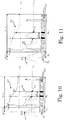
- Figure 10 is related to the controlled opening actuation of the movable contact 10 and it shows a waveform 350 of the current flowing into the phase 2; such current waveform 350 has a frequency value corresponding to the preset frequency value f P .
- control means 201 are adapted to execute method step 104 by:
- control means 201 are adapted to firstly count the predetermined number N 11 of time cycles 300, so as to define the time delay T D1 between the detection of the positive peak 155 and a starting of the controlled opening actuation of the movable contact 10.
- the duration of the time delay T D1 is initially set in the control means 102 as corresponding to the product T P ⁇ N 11 .
- control means 201 are adapted to use the subsequent predetermined number N 12 of time cycles 300 for executing the control of the opening actuation of the movable contact 10.
- the time duration T open1 of the opening actuation of the movable contact 10 is initially set in the control means 102 as corresponding to the product T P ⁇ N 12 .
- control means 201 are adapted to use a corresponding set-point value ⁇ ' associated to the opening actuation of the movable contact 10 carried out by the motor 13.
- the set-point values of the angular position ⁇ at which the motor 13 causes a separation of the movable contact 10 from the fixed contact 11 and from the fixed contact 12 are indicated as ⁇ ' S1 and ⁇ ' S2 , respectively.
- the predetermined time duration T P , the number of time cycles N 11 and the number of time cycles N 21 are preset in the control means 102 in such a way that, if the actual frequency value of the current waveform 350 corresponds to the preset frequency value f P :
- figure 11 illustrates a waveform 350 of the current flowing into the phase 2, where such current waveform 350 has a frequency value lower that the preset frequency value f P .
- the difference between the actual frequency value and the preset frequency value f P is detected by the detecting means 202 at method step 103.
- control means 201 are advantageously adapted to stretch the predetermined time duration T P of the time cycles 300 as a function of the detected frequency difference (method step 105).
- control means 201 are adapted to:
- control means 201 are advantageously adapted to:
- control means 201 are adapted to firstly count the predetermined number of time cycles N 21 , so as to define the modified time delay T D2 between the detection of the reference point 155 and a starting of the controlled opening actuation of the movable contact 10.
- the number N 21 of time cycles 300 for setting the modified time delay T D2 is equal to the number N 11 of time cycles 300 for setting the preset delay time T D1 .
- control means 201 are adapted to use the subsequent predetermined number N 22 of time cycles 300 for executing the control of the opening actuation of the movable contact 10.
- the number N 22 of time cycles 300 is equal to the number N 12 of time cycles 300.
- control means 201 are adapted to use a corresponding set-point value ⁇ ' associated to the opening actuation of the movable contact 10 carried out by the motor 13.
- the duration of the modified time delay T D2 is equal to the product T M ⁇ N 21 and the modified control profile 352 has a time duration T open2 equal to the product T M ⁇ N 22 .
- the stretched time duration T M is such that:
- the above first control condition can occur because the stretching of the time duration T M results in a stretched delay time T D2 suitable for synchronizing the execution of the time cycle 300 for reaching the set-point value ⁇ ' S1 to the actual positive going zero-crossing 151.
- the above second control condition can occur because the stretching of the time duration T M results in the stretched the time interval T I2 between the control executions for reaching the set-point values ⁇ ' S1 and ⁇ ' S2 .
- the control profile 352 is slowed to synchronize the control executions for reaching the set-point values ⁇ ' S1 and ⁇ ' S2 to the corresponding actual positive going and subsequent negative going zero-crossings 151 and 152.
- Figure 12 is related to the controlled closure actuation of the movable contact 10 and it illustrates a waveform 350 of a voltage associated to the phase 2, e.g. a voltage of the circuit into which the switching device 1 itself is installed.
- the illustrated voltage waveform 350 has a frequency value corresponding to the preset frequency value f P .
- control means 201 are adapted to execute method step 104 by:
- control means 201 are adapted to firstly count the predetermined number of time cycles N 31 , so as to define the time delay T D3 between the detection of the reference point 155 and a starting of the controlled closure actuation of the movable contact 10.
- the duration of the time delay T D3 is initially set in the control means 102 as corresponding to the product T P ⁇ N 31 .
- control means 201 are adapted to use the subsequent predetermined number N 32 of time cycles 300 for executing the control of the closure actuation of the movable contact 10.
- time duration T close1 of the closure actuation of the movable contact 10 is initially set in the control means 102 as corresponding to the product T P ⁇ N 32 .
- control means 201 are adapted to use a corresponding set-point value ⁇ ' associated to the closure actuation of the movable contact 10 carried out by the motor 13.
- the set-point values of the angular position ⁇ at which the motor 13 causes a contacting between the movable contact 10 and the fixed contact 12 and a contacting between the movable contact 10 and the fixed contact 11 are indicated as ⁇ ' S3 and ⁇ ' S4 , respectively.
- the predetermined time duration T P , the number of time cycles N 31 and the number of time cycles N 32 are preset in the control means 102 in such a way that, if the actual frequency value of the voltage waveform 350 corresponds to the preset frequency value:
- the control means 202 keeping these initial settings would fail to reach the desired synchronization between the couplings of the movable contact 10 with the fixed contacts 11, 12 and the voltage waveform 350.
- This frequency condition is detected by the detecting means 202 at method step 103.
- control means 201 are advantageously adapted to:
- control means 201 are adapted to firstly count the predetermined number N 41 of time cycles 300, so as to define the modified time delay T D4 between the detection of the reference point 155 and a starting of the controlled closure actuation of the movable contact 10.
- control means 201 are adapted to use the subsequent predetermined number N 42 of time cycles 300 for executing the control of the closure actuation of the movable contact 10.
- control means 201 are adapted to use a corresponding set-point value ⁇ ' associated to the closure actuation of the movable contact 10 carried out by the motor 13.
- the duration of the modified time delay T D4 is equal to the product T M ⁇ N 41 and the modified control profile 353 has a time duration T close2 equal to the product T M ⁇ N 42 .
- the stretched time duration T M is such that:
- the above first control condition can occur because the stretching of the time duration T M results in the stretched delay time T D4 suitable for synchronizing the execution of the time cycle 300 for reaching the set-point value ⁇ ' S3 to the actual negative peak instant 153.
- the above second control condition can occur because the stretching of the time duration T M also results in a stretched time interval T I4 between the control executions for reaching the set-point values ⁇ ' S3 and ⁇ ' S4 .
- the control profile 353 is slowed to synchronize the control executions for reaching the set-point values ⁇ ' S3 and ⁇ ' S4 to the corresponding negative peak instant 153 and subsequent positive peak instant 154 of the voltage waveform 350.
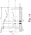
- control system 200 is adapted to execute the method 100 in case of a difference between the value of the actual distance X between the fixed contacts 11 and 12 and the nominal distance value X N is disclosed below.
- control profile 352 illustrated in figure 10 is executed by the control means 201 by using the predetermined number N 12 of time cycles 300 with the predetermined time duration T P .
- the control profile 352 is used while presuming a correspondence between the actual distance X and the preset distance value X P .
- control means 201 would control the occurrence of the set-point value ⁇ ' S2 at the corresponding negative going zero-crossing 152, presuming that such controlled angular position ⁇ ' S2 of the motor 13 is the right angular position ⁇ for causing the separation of the movable contact 10 from the fixed contact 12.
- the detecting means 202 are adapted to detect the difference between the actual distance X and the its nominal X N .
- the detecting means 202 are adapted to:
- control means 201 are advantageously adapted to stretch the predetermined time duration T D of the time cycles 300 basing on the detected difference between the elapsed time T lapse and the preset time interval T IP (method step 105).
- control means 201 are adapted to:
- control means 201 are further adapted to:
- control means 201 are adapted to firstly count the predetermined number N 21 of time cycles 300, so as to define the modified time delay T D5 between the detection of the reference point 155 and a starting of the controlled opening actuation of the movable contact 10.
- control means 201 are adapted to use the subsequent predetermined number N 22 of time cycles 300 for executing the control of the opening actuation of the movable contact 10.
- control means 201 are adapted to use a corresponding set-point value ⁇ ' associated to the opening actuation of the movable contact 10 at each time cycle 300 of the predetermined number N 22 .
- the duration of the modified time delay T D5 is equal to the product T M ⁇ N 21 and the stretched control profile 327 has a time duration T open3 equal to the product T M ⁇ N 22 .
- the real separation of the movable contact 10 from the fixed contact 12 would be controlled to occur earlier than the zero going reference point 152, at an angular set-point position ⁇ ' S6 . This is because the actual distance X between the fixed contacts 11 and 12 is smaller than the nominal distance X N .
- the stretched time duration T M is such that:
- control profile 327 is stretched such that the set-point value ⁇ ' S6 is correctly controlled at the negative going zero-crossing 152 instead of the set-point value ⁇ ' S2 .
- control method 100 and related control system 200 comprise the case of an actual frequency value of the waveform 350 not corresponding to the preset frequency value f P or the case of an actual distance X between the fixed contacts 11, 12 not corresponding to the nominal distance X N .
- control means 201 are adapted to execute the method steps 105 and 106 by modifying the preset time duration T P of the time cycles 300 according to both the detected differences.
- the initially set predetermined time duration T P of the time cycles 300 is modified by using the mechanical correcting factor K M .
- the initially set predetermined time duration T P is also modified by using the frequency correcting factor K f .
- the modified time duration T M of the time cycles 300 is equal to: T P ⁇ K M ⁇ K f .
- control method 100 and control system 200 allow achieving the intended object offering some improvements over known solutions.
- the method 100 and control system 200 allow to keep a desired synchronization between the switchings of the couple of contacts 3, 4 and a reference waveform 350, even if at least one parameter 150 associated to the phase 2 and which can influence the synchronization does not correspond to a preset value 500.
- the method 100 and control system 200 are adapted to modify the predetermined time duration T P of the control cycles 300 according to the detected difference between the actual value of the parameter 150 and the preset value 500.
- the control speed is suitably slowed or accelerated for keeping the desired synchronization.
- control speed is dynamically changed according to the variation of the actual frequency value of the reference waveform 350 with respect to the preset frequency value f P , for example by modifying the predetermined time duration T P of the cycles 300 with the correcting frequency factor K f .
- control speed is set according to the detected difference between the actual distance X and its nominal value X N , for example by modifying the predetermined time duration T P of the cycles 300 with the correcting factor K M .
- control method 100 and control system 200 thus conceived are also susceptible of modifications and variations, all of which are within the scope of the inventive concept as defined in particular by the appended claims.
- control method 100 can be applied to switching devices of a different type than the switching device 1 illustrated in figures 1-7 .
- the method 100 can be applied to a circuit breaker having for each phase one couple of contacts.
- the execution of the method 100 would be useful at least for keeping a desired synchronization between an opening switching of this couple of contacts and a predetermined electrical angle of a reference signal waveform associated to the phase, even if the actual frequency value of the reference waveform is not equal to the nominal preset value.
- the control means 201 may comprise: microcontrollers, microcomputers, minicomputers, digital signal processors (DSPs), optical computers, complex instruction set computers, application specific integrated circuits, a reduced instruction set computers, analog computers, digital computers, solid-state computers, single-board computers, or a combination of any of theses.
- DSPs digital signal processors
- optical computers complex instruction set computers, application specific integrated circuits, a reduced instruction set computers, analog computers, digital computers, solid-state computers, single-board computers, or a combination of any of theses.
- the detecting means 202 can be any electronic device or unit adapted to measure or receive a measurement of the actual value of the parameter 150, and to compare it with the preset value 500; the detecting means 202 can be separated but operatively connected to the control means 201, or they can be implemented into the control means 201 themselves.
- the detecting means 203 can be any electronic device or unit adapted to detect the occurrence of the reference pint 155 of the waveform 350, the detecting means 203 can separated but operatively connected to the control means 201, or they can be implemented into control means 201.
Landscapes
- Engineering & Computer Science (AREA)
- Power Engineering (AREA)
- Keying Circuit Devices (AREA)
- Control Of Ac Motors In General (AREA)
- Control Of Linear Motors (AREA)
Claims (16)
- Verfahren (100) zum Steuern einer Schaltvorrichtung (1) mit zumindest einer Phase (2), die zumindest ein Paar Kontakte (3, 4) aufweist, die zum Umschalten zwischen einem geschlossenen Zustand, bei dem die Kontakte (10-12, 10-11) miteinander verbunden sind, und einem offenen Zustand, bei dem die Kontakte (10-11, 10-12) voneinander getrennt sind, angesteuert werden können, wobei das Verfahren (100) aufweist:a) Bereitstellen (101) einer Steuereinrichtung (201) zum Steuern einer Ansteuerung des zumindest einen Paars Kontakte (3, 4), wobei die Steuereinrichtung (201) darauf ausgelegt ist, unter Verwendung von Zeitzyklen (300) zu funktionieren;b) Einstellen (102) der Zeitzyklen (300) auf eine vorgegebene Zeitdauer (TP);c) Erfassen (103) einer Differenz eines Werts eines Parameters (150), der der Phase (2) in Bezug auf einen voreingestellten Wert (500) zugeordnet ist;d) falls der Wert des Parameters (150) dem voreingestellten Wert (500) gleicht, Steuern (104) der Ansteuerung des zumindest einen Paars Kontaktedadurch gekennzeichnet, dass es aufweist:
(3, 4) durch die Steuereinrichtung (201) unter Verwendung der Zeitzyklen (300) mit der vorgegebenen Zeitdauer (TP), so dass das Umschalten zwischen dem offenen und dem geschlossenen Zustand so gesteuert wird, dass es bei einem vorgegebenen elektrischen Winkel (151, 152, 153, 154) einer Wellenform (350) eines elektrischen Signals geschieht, das der Phase (2) zugeordnet ist;e) wenn die Differenz erfasst wird, Modifizieren (105) der vorgegebenen Zeitdauer (TP) gemäß der erfassten Differenz, undf) Steuern (106) der Ansteuerung des zumindest einen Paars Kontakte (3, 4) durch die Steuereinrichtung (201) unter Verwendung der Zeitzyklen (300) mit der modifizierten Zeitdauer (TM), wobei die Modifikation der vorgegebenen Zeitdauer (TP) dergestalt ist, dass das Umschalten zwischen dem offenen und dem geschlossenen Zustand so gesteuert wird, dass es bei einem vorgegebenen elektrischen Winkel (151, 152, 153, 154) der Wellenform (350) geschieht. - Verfahren (100) nach Anspruch 1, wobei Schritt c) aufweist:- Messen (107) des Werts des Parameters (150); und- Vergleichen (108) des gemessenen Werts mit dem voreingestellten Wert (500); und wobei Schritt e) aufweist:- Berechnen (109) eines Korrekturfaktors (Kf, KM) unter Verwendung des voreingestellten Werts (500) und des gemessenen Werts des Parameters (150); und- Anwenden (110) des Korrekturfaktors (Kf, KM) auf die vorgegebene Zeitdauer (TP).
- Verfahren (100) nach Anspruch 1 oder 2, wobei:- Schritte d) und f) ein Erfassen (111) eines Referenzpunkts (155) der Wellenform (350) aufweist;- der Schritt d) ein Einstellen (112) für die Steuereinrichtung (201) einer ersten vorgegebenen Zahl (N1, N3) an Zeitzyklen (300) bei der vorgegebenen Zeitdauer (TP) aufweist, beginnend an der Erfassung des zumindest einen Referenzpunkts (155);- Schritt f) ein Einstellen (113) für die Steuereinrichtung (201) einer zweiten vorgegebenen Zahl (N2, N4) an Zeitzyklen (300) bei der modifizierten Zeitdauer (TM) aufweist, beginnend an der Erfassung des zumindest einen Referenzpunkts (155);wobei die zweite vorgegebene Zahl (N2, N4) der ersten vorgegebenen Zahl (N1, N3) gleicht.
- Verfahren (100) nach Anspruch 3, wobei:- die erste vorgegebene Zahl (N1, N3) an Zeitzyklen (300) eine vordefinierte Zahl (N11, N31) an ersten Zeitzyklen (300) aufweist, die eine Zeitverzögerung (TD1, TD3) zwischen der Erfassung des zumindest einen Referenzpunkts (155) und einem Beginn der Ansteuerung des zumindest einen Paars Kontakte (3, 4) definiert;- die zweite vorgegebene Zahl (N2, N4) an Zeitzyklen (300) eine vordefinierte Zahl an zweiten Zeitzyklen (N21, N41) aufweist, die eine Zeitverzögerung (TD2, TD5, TD4) zwischen der Erfassung des zumindest einen Referenzpunkts (155) und einem Beginn der Ansteuerung des zumindest einen Paars Kontakte (3, 4) definiert.
- Verfahren (100) nach Anspruch 3 oder 4, wobei:- die erste vorgegebene Zahl (N1, N3) an Zeitzyklen (300) eine vorgegebene Zahl (N12, N32) an dritten Zeitzyklen (300) aufweist, die eine erste Zeitdauer (Topen1, Tclose1) für die Ansteuerung des zumindest einen Paars Kontakte (3, 4) definiert; und- die zweite vorgegebene Zahl (N2, N4) an Zeitzyklen (300) eine vorgegebene Zahl (N22, N42) an vierten Zeitzyklen (300) aufweist, die eine zweite Zeitdauer (Topen2, Topen3, Tclose2) für die Ansteuerung des zumindest einen Paars Kontakte (3, 4) definiert;- Schritt d) ein Steuern (112) der Ansteuerung des zumindest einen Paars Kontakte (3, 4) während jedem der dritten Zeitzyklen (300) durch Verwendung eines geschlossenen Regelkreises aufweist; und- Schritt f) ein Steuern (113) der Ansteuerung des zumindest einen Paars Kontakte (3, 4) während jedem der vierten Zeitzyklen (100) durch Verwendung eines geschlossenen Regelkreises aufweist.
- Verfahren (100) nach einem oder mehreren der vorgenannten Ansprüche, wobei der Parameter (150) die Frequenz der Wellenform (350) des elektrischen Signals ist.
- Steuersystem (200) zum Steuern einer Schaltvorrichtung (1) mit zumindest einer Phase (2), die zumindest ein Paar Kontakte (3, 4) aufweist, die zum Umschalten zwischen einem geschlossenen Zustand, bei dem die Kontakte (10-12, 10-11) miteinander verbunden sind, und einem offenen Zustand, bei dem die Kontakte (10-11, 10-12) voneinander getrennt sind, angesteuert werden können, wobei das Steuersystem (200) aufweist:- eine Steuereinrichtung (201) zum Steuern einer Ansteuerung des zumindest einen Paars Kontakte (3, 4), wobei die Steuereinrichtung (201) darauf ausgelegt ist, unter Verwendung von Zeitzyklen (300) zu funktionieren, und wobei die Zeitzyklen mit einer vorgegebenen Zeitdauer (TP) eingestellt sind;- eine Einrichtung (201) zum Erfassen einer Differenz eines Werts eines Parameters (150), der der Phase (2) in Bezug auf einen voreingestellten Wert (500) zugeordnet ist;wobei, falls der Wert des Parameters (150) dem voreingestellten Wert (500) gleicht, die Steuereinrichtung darauf ausgelegt ist, die Ansteuerung des zumindest einen Paars Kontakte (3, 4) durch die Steuereinrichtung (201) unter Verwendung der Zeitzyklen (300) mit der vorgegebenen Zeitdauer (TP) zu steuern, so dass das Umschalten zwischen dem offenen und dem geschlossenen Zustand so gesteuert wird, dass es bei einem vorgegebenen elektrischen Winkel (151, 152, 153, 154) einer Wellenform (350) eines elektrischen Signals geschieht, das der Phase (2) zugeordnet ist;
dadurch gekennzeichnet, dass die Steuereinrichtung (201) auf Folgendes ausgelegt ist:- wenn die Differenz zwischen dem Wert des Parameters (150) und dem voreingestellten Wert (500) erfasst wird, Modifizieren der vorgegebenen Zeitdauer (TP) gemäß der erfassten Differenz; und- Steuern der Ansteuerung des zumindest einen Paars Kontakte (3, 4) unter Verwendung der Zeitzyklen (300) mit der modifizierten Zeitdauer (TM), wobei die Modifikation der vorgegebenen Zeitdauer (TP) dergestalt ist, dass das Umschalten zwischen dem geschlossenen und dem offenen Zustand durch die Steuereinrichtung (201) gesteuert wird, so dass es bei einem vorgegebenen elektrischen Winkel (151, 152, 153, 154) der Wellenform (350) geschieht. - Steuersystem (200) nach Anspruch 7, wobei die Erfassungseinrichtung (202) auf Folgendes ausgelegt ist:- Messen oder Empfangen einer Messung des Werts des Parameters (150); und- Vergleichen des gemessenen Werts der Parameter (150) in Bezug auf den voreingestellten Wert (500);und wobei die Steuereinrichtung (201) auf Folgendes ausgelegt ist:- Berechnen eines Korrekturfaktors (Kf, KM) unter Verwendung des voreingestellten Werts (500) und des gemessenen Werts des Parameters (150); und- Anwenden des Korrekturfaktors (Kf, KM) auf die vorgegebene Zeitdauer (TP).
- Steuersystem (200) nach Anspruch 7 oder 8, aufweisend eine Einrichtung (203) zum Erfassen eines Referenzpunkts (155) der Wellenform (350) des elektrischen Signals, und wobei die Steuereinrichtung (201) auf Folgendes ausgelegt ist:- Verwendung einer ersten vorgegebenen Zahl (N1, N3) an Zeitzyklen (300) bei der vorgegebenen Zeitdauer (TP), beginnend an der Erfassung des zumindest einen Referenzpunkts (155), falls der Wert des Parameters (150) dem voreingestellten Wert (500) gleicht; und- Verwendung einer zweiten vorgegebenen Zahl (N2, N4) an Zeitzyklen (300) bei der modifizierten Zeitdauer (TM), beginnend an der Erfassung des zumindest einen Referenzpunkts (155), falls die Differenz zwischen dem Wert des Parameters (150) und dem voreingestellten Wert (500) erfasst wird;wobei die zweite vorgegebene Zahl (N2, N4) der ersten vorgegebenen Zahl (N1, N3) gleicht.
- Steuersystem (200) nach Anspruch 9, wobei:- die erste vorgegebene Zahl (N1, N3) an Zeitzyklen (300) eine vorgegebene Zahl (N11, N31) an ersten Zeitzyklen (300) aufweist, die eine Zeitverzögerung (TD1, TD3) zwischen der Erfassung des zumindest einen Referenzpunkts (155) und einem Beginn der Ansteuerung des zumindest einen Paars Kontakte (3, 4) definiert;- die zweite vorgegebene Zahl (N2, N4) an Zeitzyklen (300) eine vorgegebene Zahl an zweiten Zeitzyklen (N21, N41) aufweist, die eine Zeitverzögerung (TD2, TD5, TD4) zwischen der Erfassung des zumindest einen Referenzpunkts (155) und einem Beginn der Ansteuerung des zumindest einen Paars Kontakte (3, 4) definiert.
- Steuersystem (200) nach Anspruch 9 oder 10, wobei:- die erste vorgegebene Zahl (N1, N3) an Zeitzyklen (300) eine vorgegebene Zahl (N12, N32) an dritten Zeitzyklen (300) aufweist, die eine erste Zeitdauer (Topen1, Topen2, Tclose1) für die Ansteuerung des zumindest einen Paars Kontakte (3, 4) definiert; und- die zweite vorgegebene Zahl (N2, N4) an Zeitzyklen (300) eine vorgegebene Zahl (N22, N42) an vierten Zeitzyklen (300) aufweist, die eine zweite Zeitdauer (Topen2, Topen3, Tclose2) für die Ansteuerung des zumindest einen Paars Kontakte (3, 4) definiert;und wobei die Steuereinrichtung (201) auf Folgendes ausgelegt ist:- Steuern der Ansteuerung des zumindest einen Paars Kontakte (3, 4) während jedem der dritten Zeitzyklen (300) durch Verwendung eines geschlossenen Regelkreises;- Steuern der Ansteuerung des zumindest einen Paars Kontakte (3, 4) während jedem der vierten Zeitzyklen (100) durch Verwendung eines geschlossenen Regelkreises.
- Steuersystem (100) nach einem oder mehreren der vorgenannten Ansprüche 7 bis 11, wobei:- die Schaltvorrichtung (1) darauf ausgelegt ist, zwei Teile (5, 6) eines Stromkreises miteinander zu verbinden oder voneinander zu trennen;- die Phase (2) zumindest eine Halbleitervorrichtung (30) aufweist, die darauf ausgelegt ist, einen Strom, der in einer ersten Richtung hindurchfließt, zu blockieren, und es einem Strom zu ermöglichen, in einer zweiten Richtung hindurchzufließen, die der ersten Richtung entgegengesetzt ist;wobei das zumindest eine Paar Kontakte (3, 4) aufweist:- ein erstes Paar Kontakte (3), das darauf ausgelegt ist, durch sein Umschalten von dem offenen Zustand auf den geschlossenen Zustand eine Reihenverbindung der zumindest einen Halbleitervorrichtung (30) zwischen den zwei Teilen 85, 6) des Stromkreises herbeizuführen;- ein zweites Paar Kontakte (4), das darauf ausgelegt ist, durch sein Umschalten von dem offenen Zustand auf den geschlossenen Zustand die zumindest eine Halbleitervorrichtung (30) kurzzuschließen;und wobei die Steuereinrichtung (201) darauf ausgelegt ist, die Ansteuerung der ersten und zweiten Paare Kontakte (3, 4) so zu steuern, dass:- das Umschalten des zweiten Paars Kontakte (4) von dem geschlossenen Zustand auf den offenen Zustand und das Umschalten des ersten Paars Kontakte (3) von dem geschlossenen Zustand auf den offenen Zustand bei einem ersten vorgegebenen elektrischen Winkel (151) und einem zweiten, folgenden, vorgegebenen elektrischen Winkel (152) der Wellenform (350) erfolgt;- das Umschalten des ersten Paars Kontakte (3) von dem offenen Zustand auf den geschlossenen Zustand und das Umschalten des zweiten Paars Kontakte (4) von dem offenen Zustand auf den geschlossenen Zustand bei einem dritten vorgegebenen elektrischen Winkel (153) und bei einem vierten, folgenden, vorgegebenen elektrischen Winkel (154) der Wellenform (350) erfolgt.
- Steuersystem (200) nach Anspruch 12, wobei der Parameter (150) die Entfernung (X) zwischen einem Kontakt (12) des ersten Paars Kontakte (3) und einem Kontakt (11) des zweiten Paars Kontakte (4) aufweist.
- Steuersystem (200) nach einem oder mehreren der vorgenannten Ansprüche 7 bis 13, wobei der Parameter (150) die Frequenz der Wellenform (350) des elektrischen Signals aufweist.
- Schaltvorrichtung (1), dadurch gekennzeichnet, dass sie ein Steuersystem (200) nach einem oder mehreren der Ansprüche 7 bis 14 aufweist.
- Schaltgerät, dadurch gekennzeichnet, dass es ein Steuersystem (200) nach einem oder mehreren der Ansprüche 7 bis 14 und/oder eine Schaltvorrichtung (1) nach Anspruch 15 aufweist.
Priority Applications (7)
| Application Number | Priority Date | Filing Date | Title |
|---|---|---|---|
| ES15150502.1T ES2663838T3 (es) | 2015-01-08 | 2015-01-08 | Método y sistema de control para controlar un dispositivo de conmutación |
| HUE15150502A HUE038370T2 (hu) | 2015-01-08 | 2015-01-08 | Eljárás és vezérlõ rendszer kapcsoló eszköz vezérlésére |
| EP15150502.1A EP3043365B1 (de) | 2015-01-08 | 2015-01-08 | Verfahren und Steuerungssystem zur Steuerung einer Schaltvorrichtung |
| PL15150502T PL3043365T3 (pl) | 2015-01-08 | 2015-01-08 | Sposób i układ sterowania dla sterowania urządzeniem przełączającym |
| DK15150502.1T DK3043365T3 (en) | 2015-01-08 | 2015-01-08 | Method and control system for controlling a switching device |
| US14/983,627 US9899161B2 (en) | 2015-01-08 | 2015-12-30 | Method and control system for controlling a switching device |
| CN201610007279.5A CN105788915B (zh) | 2015-01-08 | 2016-01-06 | 用于控制开关装置的方法和控制系统 |
Applications Claiming Priority (1)
| Application Number | Priority Date | Filing Date | Title |
|---|---|---|---|
| EP15150502.1A EP3043365B1 (de) | 2015-01-08 | 2015-01-08 | Verfahren und Steuerungssystem zur Steuerung einer Schaltvorrichtung |
Publications (2)
| Publication Number | Publication Date |
|---|---|
| EP3043365A1 EP3043365A1 (de) | 2016-07-13 |
| EP3043365B1 true EP3043365B1 (de) | 2017-12-27 |
Family
ID=52232119
Family Applications (1)
| Application Number | Title | Priority Date | Filing Date |
|---|---|---|---|
| EP15150502.1A Active EP3043365B1 (de) | 2015-01-08 | 2015-01-08 | Verfahren und Steuerungssystem zur Steuerung einer Schaltvorrichtung |
Country Status (7)
| Country | Link |
|---|---|
| US (1) | US9899161B2 (de) |
| EP (1) | EP3043365B1 (de) |
| CN (1) | CN105788915B (de) |
| DK (1) | DK3043365T3 (de) |
| ES (1) | ES2663838T3 (de) |
| HU (1) | HUE038370T2 (de) |
| PL (1) | PL3043365T3 (de) |
Families Citing this family (4)
| Publication number | Priority date | Publication date | Assignee | Title |
|---|---|---|---|---|
| USD880435S1 (en) * | 2018-07-02 | 2020-04-07 | Abb Schweiz Ag | Cover plate for switches |
| CN109239504B (zh) * | 2018-08-03 | 2020-04-07 | 同济大学 | 一种旋转式转换开关触点通断角度时序波形的测试方法 |
| USD883232S1 (en) * | 2018-12-31 | 2020-05-05 | Abb Schweiz Ag | Switch with a cover plate |
| EP3745433B1 (de) * | 2019-05-29 | 2023-07-05 | ABB Schweiz AG | Verbesserte diagnostische lösungen für mittelspannungsschaltvorrichtungen |
Family Cites Families (7)
| Publication number | Priority date | Publication date | Assignee | Title |
|---|---|---|---|---|
| JP2892717B2 (ja) * | 1989-11-15 | 1999-05-17 | 株式会社日立製作所 | 電力開閉制御装置 |
| US5821642A (en) * | 1996-11-04 | 1998-10-13 | Hubbell Incorporated | Arc prevention circuit for a mechanical switch |
| JP5159075B2 (ja) * | 2006-09-25 | 2013-03-06 | 株式会社東芝 | 遮断器の開閉制御装置 |
| CA2806254C (en) * | 2010-07-27 | 2016-01-26 | Mitsubishi Electric Corporation | Phase control switching device |
| JP5651508B2 (ja) * | 2011-03-17 | 2015-01-14 | 株式会社東芝 | 突入電流抑制装置 |
| WO2012152793A1 (en) * | 2011-05-09 | 2012-11-15 | Abb Technology Ag | Automatic acquisition of circuit breaker operating times for controlled switching |
| EP2523203B1 (de) | 2011-05-10 | 2019-07-03 | ABB Schweiz AG | Schaltvorrichtung und zugehörige Schaltanlage |
-
2015
- 2015-01-08 EP EP15150502.1A patent/EP3043365B1/de active Active
- 2015-01-08 ES ES15150502.1T patent/ES2663838T3/es active Active
- 2015-01-08 HU HUE15150502A patent/HUE038370T2/hu unknown
- 2015-01-08 DK DK15150502.1T patent/DK3043365T3/en active
- 2015-01-08 PL PL15150502T patent/PL3043365T3/pl unknown
- 2015-12-30 US US14/983,627 patent/US9899161B2/en active Active
-
2016
- 2016-01-06 CN CN201610007279.5A patent/CN105788915B/zh active Active
Non-Patent Citations (1)
| Title |
|---|
| None * |
Also Published As
| Publication number | Publication date |
|---|---|
| PL3043365T3 (pl) | 2018-08-31 |
| US9899161B2 (en) | 2018-02-20 |
| ES2663838T3 (es) | 2018-04-17 |
| EP3043365A1 (de) | 2016-07-13 |
| US20160203924A1 (en) | 2016-07-14 |
| CN105788915A (zh) | 2016-07-20 |
| HUE038370T2 (hu) | 2018-10-29 |
| DK3043365T3 (en) | 2018-03-26 |
| CN105788915B (zh) | 2019-05-07 |
Similar Documents
| Publication | Publication Date | Title |
|---|---|---|
| US9263213B2 (en) | Power switching control device and closing control method thereof | |
| TWI617109B (zh) | 無效功率補償器 | |
| EP3043365B1 (de) | Verfahren und Steuerungssystem zur Steuerung einer Schaltvorrichtung | |
| EP3439166B1 (de) | Pcb-motorsteuergerät mit pow-schaltung | |
| US9082562B2 (en) | Inrush-current suppressing device and inrush-current suppressing method | |
| JP2009059662A (ja) | 電力開閉装置およびその制御方法 | |
| CN1263056C (zh) | 用于控制电开关装置的打开与闭合的装置和方法 | |
| US5808851A (en) | Controlled switching | |
| JP2012059447A (ja) | 電気量波形の立ち上がりタイミング検出方法および遮断器の同期開閉制御装置 | |
| EP3439165B1 (de) | Motorstarter auf leiterplattenbasis | |
| CN106356878B (zh) | 一种基于波形拟合的相间负荷转移方法 | |
| EP2372739B1 (de) | Phasensteuerungs-schaltanlage und verfahren zum steuern einer schaltanlage | |
| JP2013024682A (ja) | 電流不導通検出装置および電流不導通検出方法 | |
| US20200058455A1 (en) | Pow switching device with enhanced programming | |
| CN106575582B (zh) | 具有并行开关路径的电开关设备 | |
| JP2007166844A (ja) | 電源切替装置 | |
| Sutaya et al. | Analysis and Simulation of Current Zero Crossing Time Interval Under Different Loads | |
| CN110535110A (zh) | 特高压交流变压器选相分合闸控制方法及装置 | |
| JPH01251528A (ja) | 遮断器用同期投入装置 | |
| JPH03148071A (ja) | 電磁接触器の動作状態監視装置 | |
| JP2012182151A (ja) | 電力開閉装置およびその制御方法 |
Legal Events
| Date | Code | Title | Description |
|---|---|---|---|
| PUAI | Public reference made under article 153(3) epc to a published international application that has entered the european phase |
Free format text: ORIGINAL CODE: 0009012 |
|
| AK | Designated contracting states |
Kind code of ref document: A1 Designated state(s): AL AT BE BG CH CY CZ DE DK EE ES FI FR GB GR HR HU IE IS IT LI LT LU LV MC MK MT NL NO PL PT RO RS SE SI SK SM TR |
|
| AX | Request for extension of the european patent |
Extension state: BA ME |
|
| 17P | Request for examination filed |
Effective date: 20170111 |
|
| RBV | Designated contracting states (corrected) |
Designated state(s): AL AT BE BG CH CY CZ DE DK EE ES FI FR GB GR HR HU IE IS IT LI LT LU LV MC MK MT NL NO PL PT RO RS SE SI SK SM TR |
|
| RAP1 | Party data changed (applicant data changed or rights of an application transferred) |
Owner name: ABB SCHWEIZ AG |
|
| GRAP | Despatch of communication of intention to grant a patent |
Free format text: ORIGINAL CODE: EPIDOSNIGR1 |
|
| INTG | Intention to grant announced |
Effective date: 20170719 |
|
| GRAS | Grant fee paid |
Free format text: ORIGINAL CODE: EPIDOSNIGR3 |
|
| GRAA | (expected) grant |
Free format text: ORIGINAL CODE: 0009210 |
|
| AK | Designated contracting states |
Kind code of ref document: B1 Designated state(s): AL AT BE BG CH CY CZ DE DK EE ES FI FR GB GR HR HU IE IS IT LI LT LU LV MC MK MT NL NO PL PT RO RS SE SI SK SM TR |
|
| REG | Reference to a national code |
Ref country code: GB Ref legal event code: FG4D |
|
| REG | Reference to a national code |
Ref country code: CH Ref legal event code: EP |
|
| REG | Reference to a national code |
Ref country code: AT Ref legal event code: REF Ref document number: 958971 Country of ref document: AT Kind code of ref document: T Effective date: 20180115 |
|
| REG | Reference to a national code |
Ref country code: FR Ref legal event code: PLFP Year of fee payment: 4 |
|
| REG | Reference to a national code |
Ref country code: IE Ref legal event code: FG4D |
|
| REG | Reference to a national code |
Ref country code: DE Ref legal event code: R096 Ref document number: 602015006909 Country of ref document: DE |
|
| REG | Reference to a national code |
Ref country code: DK Ref legal event code: T3 Effective date: 20180323 |
|
| REG | Reference to a national code |
Ref country code: ES Ref legal event code: FG2A Ref document number: 2663838 Country of ref document: ES Kind code of ref document: T3 Effective date: 20180417 |
|
| PG25 | Lapsed in a contracting state [announced via postgrant information from national office to epo] |
Ref country code: FI Free format text: LAPSE BECAUSE OF FAILURE TO SUBMIT A TRANSLATION OF THE DESCRIPTION OR TO PAY THE FEE WITHIN THE PRESCRIBED TIME-LIMIT Effective date: 20171227 Ref country code: LT Free format text: LAPSE BECAUSE OF FAILURE TO SUBMIT A TRANSLATION OF THE DESCRIPTION OR TO PAY THE FEE WITHIN THE PRESCRIBED TIME-LIMIT Effective date: 20171227 Ref country code: NO Free format text: LAPSE BECAUSE OF FAILURE TO SUBMIT A TRANSLATION OF THE DESCRIPTION OR TO PAY THE FEE WITHIN THE PRESCRIBED TIME-LIMIT Effective date: 20180327 |
|
| REG | Reference to a national code |
Ref country code: NL Ref legal event code: MP Effective date: 20171227 |
|
| REG | Reference to a national code |
Ref country code: LT Ref legal event code: MG4D |
|
| REG | Reference to a national code |
Ref country code: AT Ref legal event code: MK05 Ref document number: 958971 Country of ref document: AT Kind code of ref document: T Effective date: 20171227 |
|
| PG25 | Lapsed in a contracting state [announced via postgrant information from national office to epo] |
Ref country code: BG Free format text: LAPSE BECAUSE OF FAILURE TO SUBMIT A TRANSLATION OF THE DESCRIPTION OR TO PAY THE FEE WITHIN THE PRESCRIBED TIME-LIMIT Effective date: 20180327 Ref country code: RS Free format text: LAPSE BECAUSE OF FAILURE TO SUBMIT A TRANSLATION OF THE DESCRIPTION OR TO PAY THE FEE WITHIN THE PRESCRIBED TIME-LIMIT Effective date: 20171227 Ref country code: LV Free format text: LAPSE BECAUSE OF FAILURE TO SUBMIT A TRANSLATION OF THE DESCRIPTION OR TO PAY THE FEE WITHIN THE PRESCRIBED TIME-LIMIT Effective date: 20171227 Ref country code: GR Free format text: LAPSE BECAUSE OF FAILURE TO SUBMIT A TRANSLATION OF THE DESCRIPTION OR TO PAY THE FEE WITHIN THE PRESCRIBED TIME-LIMIT Effective date: 20180328 Ref country code: HR Free format text: LAPSE BECAUSE OF FAILURE TO SUBMIT A TRANSLATION OF THE DESCRIPTION OR TO PAY THE FEE WITHIN THE PRESCRIBED TIME-LIMIT Effective date: 20171227 |
|
| PG25 | Lapsed in a contracting state [announced via postgrant information from national office to epo] |
Ref country code: NL Free format text: LAPSE BECAUSE OF FAILURE TO SUBMIT A TRANSLATION OF THE DESCRIPTION OR TO PAY THE FEE WITHIN THE PRESCRIBED TIME-LIMIT Effective date: 20171227 |
|
| PG25 | Lapsed in a contracting state [announced via postgrant information from national office to epo] |
Ref country code: CY Free format text: LAPSE BECAUSE OF FAILURE TO SUBMIT A TRANSLATION OF THE DESCRIPTION OR TO PAY THE FEE WITHIN THE PRESCRIBED TIME-LIMIT Effective date: 20171227 Ref country code: SK Free format text: LAPSE BECAUSE OF FAILURE TO SUBMIT A TRANSLATION OF THE DESCRIPTION OR TO PAY THE FEE WITHIN THE PRESCRIBED TIME-LIMIT Effective date: 20171227 Ref country code: EE Free format text: LAPSE BECAUSE OF FAILURE TO SUBMIT A TRANSLATION OF THE DESCRIPTION OR TO PAY THE FEE WITHIN THE PRESCRIBED TIME-LIMIT Effective date: 20171227 Ref country code: CZ Free format text: LAPSE BECAUSE OF FAILURE TO SUBMIT A TRANSLATION OF THE DESCRIPTION OR TO PAY THE FEE WITHIN THE PRESCRIBED TIME-LIMIT Effective date: 20171227 |
|
| PG25 | Lapsed in a contracting state [announced via postgrant information from national office to epo] |
Ref country code: SM Free format text: LAPSE BECAUSE OF FAILURE TO SUBMIT A TRANSLATION OF THE DESCRIPTION OR TO PAY THE FEE WITHIN THE PRESCRIBED TIME-LIMIT Effective date: 20171227 Ref country code: AT Free format text: LAPSE BECAUSE OF FAILURE TO SUBMIT A TRANSLATION OF THE DESCRIPTION OR TO PAY THE FEE WITHIN THE PRESCRIBED TIME-LIMIT Effective date: 20171227 Ref country code: RO Free format text: LAPSE BECAUSE OF FAILURE TO SUBMIT A TRANSLATION OF THE DESCRIPTION OR TO PAY THE FEE WITHIN THE PRESCRIBED TIME-LIMIT Effective date: 20171227 Ref country code: IS Free format text: LAPSE BECAUSE OF FAILURE TO SUBMIT A TRANSLATION OF THE DESCRIPTION OR TO PAY THE FEE WITHIN THE PRESCRIBED TIME-LIMIT Effective date: 20180427 |
|
| REG | Reference to a national code |
Ref country code: CH Ref legal event code: PL |
|
| PG25 | Lapsed in a contracting state [announced via postgrant information from national office to epo] |
Ref country code: MC Free format text: LAPSE BECAUSE OF FAILURE TO SUBMIT A TRANSLATION OF THE DESCRIPTION OR TO PAY THE FEE WITHIN THE PRESCRIBED TIME-LIMIT Effective date: 20171227 |
|
| REG | Reference to a national code |
Ref country code: DE Ref legal event code: R097 Ref document number: 602015006909 Country of ref document: DE |
|
| REG | Reference to a national code |
Ref country code: HU Ref legal event code: AG4A Ref document number: E038370 Country of ref document: HU |
|
| PG25 | Lapsed in a contracting state [announced via postgrant information from national office to epo] |
Ref country code: LU Free format text: LAPSE BECAUSE OF NON-PAYMENT OF DUE FEES Effective date: 20180108 |
|
| REG | Reference to a national code |
Ref country code: IE Ref legal event code: MM4A |
|
| PLBE | No opposition filed within time limit |
Free format text: ORIGINAL CODE: 0009261 |
|
| STAA | Information on the status of an ep patent application or granted ep patent |
Free format text: STATUS: NO OPPOSITION FILED WITHIN TIME LIMIT |
|
| REG | Reference to a national code |
Ref country code: BE Ref legal event code: MM Effective date: 20180131 |
|
| PG25 | Lapsed in a contracting state [announced via postgrant information from national office to epo] |
Ref country code: CH Free format text: LAPSE BECAUSE OF NON-PAYMENT OF DUE FEES Effective date: 20180131 Ref country code: LI Free format text: LAPSE BECAUSE OF NON-PAYMENT OF DUE FEES Effective date: 20180131 Ref country code: BE Free format text: LAPSE BECAUSE OF NON-PAYMENT OF DUE FEES Effective date: 20180131 |
|
| 26N | No opposition filed |
Effective date: 20180928 |
|
| PG25 | Lapsed in a contracting state [announced via postgrant information from national office to epo] |
Ref country code: IE Free format text: LAPSE BECAUSE OF NON-PAYMENT OF DUE FEES Effective date: 20180108 |
|
| PG25 | Lapsed in a contracting state [announced via postgrant information from national office to epo] |
Ref country code: SI Free format text: LAPSE BECAUSE OF FAILURE TO SUBMIT A TRANSLATION OF THE DESCRIPTION OR TO PAY THE FEE WITHIN THE PRESCRIBED TIME-LIMIT Effective date: 20171227 |
|
| PGFP | Annual fee paid to national office [announced via postgrant information from national office to epo] |
Ref country code: PL Payment date: 20190103 Year of fee payment: 5 |
|
| PGFP | Annual fee paid to national office [announced via postgrant information from national office to epo] |
Ref country code: HU Payment date: 20190123 Year of fee payment: 5 |
|
| PG25 | Lapsed in a contracting state [announced via postgrant information from national office to epo] |
Ref country code: MT Free format text: LAPSE BECAUSE OF NON-PAYMENT OF DUE FEES Effective date: 20180108 |
|
| PG25 | Lapsed in a contracting state [announced via postgrant information from national office to epo] |
Ref country code: PT Free format text: LAPSE BECAUSE OF FAILURE TO SUBMIT A TRANSLATION OF THE DESCRIPTION OR TO PAY THE FEE WITHIN THE PRESCRIBED TIME-LIMIT Effective date: 20171227 |
|
| PG25 | Lapsed in a contracting state [announced via postgrant information from national office to epo] |
Ref country code: SE Free format text: LAPSE BECAUSE OF FAILURE TO SUBMIT A TRANSLATION OF THE DESCRIPTION OR TO PAY THE FEE WITHIN THE PRESCRIBED TIME-LIMIT Effective date: 20171227 Ref country code: MK Free format text: LAPSE BECAUSE OF NON-PAYMENT OF DUE FEES Effective date: 20171227 |
|
| PG25 | Lapsed in a contracting state [announced via postgrant information from national office to epo] |
Ref country code: AL Free format text: LAPSE BECAUSE OF FAILURE TO SUBMIT A TRANSLATION OF THE DESCRIPTION OR TO PAY THE FEE WITHIN THE PRESCRIBED TIME-LIMIT Effective date: 20171227 |
|
| PG25 | Lapsed in a contracting state [announced via postgrant information from national office to epo] |
Ref country code: HU Free format text: LAPSE BECAUSE OF NON-PAYMENT OF DUE FEES Effective date: 20200109 |
|
| PG25 | Lapsed in a contracting state [announced via postgrant information from national office to epo] |
Ref country code: PL Free format text: LAPSE BECAUSE OF NON-PAYMENT OF DUE FEES Effective date: 20200108 |
|
| PGFP | Annual fee paid to national office [announced via postgrant information from national office to epo] |
Ref country code: DE Payment date: 20250121 Year of fee payment: 11 |
|
| PGFP | Annual fee paid to national office [announced via postgrant information from national office to epo] |
Ref country code: DK Payment date: 20250124 Year of fee payment: 11 |
|
| PGFP | Annual fee paid to national office [announced via postgrant information from national office to epo] |
Ref country code: ES Payment date: 20250226 Year of fee payment: 11 |
|
| PGFP | Annual fee paid to national office [announced via postgrant information from national office to epo] |
Ref country code: FR Payment date: 20250127 Year of fee payment: 11 |
|
| PGFP | Annual fee paid to national office [announced via postgrant information from national office to epo] |
Ref country code: IT Payment date: 20250129 Year of fee payment: 11 Ref country code: GB Payment date: 20250128 Year of fee payment: 11 |
|
| PGFP | Annual fee paid to national office [announced via postgrant information from national office to epo] |
Ref country code: TR Payment date: 20250102 Year of fee payment: 11 |