EP3043220B1 - Device and method for monitoring the function of a safety switching device - Google Patents
Device and method for monitoring the function of a safety switching device Download PDFInfo
- Publication number
- EP3043220B1 EP3043220B1 EP15200414.9A EP15200414A EP3043220B1 EP 3043220 B1 EP3043220 B1 EP 3043220B1 EP 15200414 A EP15200414 A EP 15200414A EP 3043220 B1 EP3043220 B1 EP 3043220B1
- Authority
- EP
- European Patent Office
- Prior art keywords
- signal
- input
- output
- test
- function
- Prior art date
- Legal status (The legal status is an assumption and is not a legal conclusion. Google has not performed a legal analysis and makes no representation as to the accuracy of the status listed.)
- Active
Links
Images


Classifications
-
- G—PHYSICS
- G01—MEASURING; TESTING
- G01R—MEASURING ELECTRIC VARIABLES; MEASURING MAGNETIC VARIABLES
- G01R31/00—Arrangements for testing electric properties; Arrangements for locating electric faults; Arrangements for electrical testing characterised by what is being tested not provided for elsewhere
- G01R31/327—Testing of circuit interrupters, switches or circuit-breakers
- G01R31/3277—Testing of circuit interrupters, switches or circuit-breakers of low voltage devices, e.g. domestic or industrial devices, such as motor protections, relays, rotation switches
- G01R31/3278—Testing of circuit interrupters, switches or circuit-breakers of low voltage devices, e.g. domestic or industrial devices, such as motor protections, relays, rotation switches of relays, solenoids or reed switches
-
- G—PHYSICS
- G05—CONTROLLING; REGULATING
- G05B—CONTROL OR REGULATING SYSTEMS IN GENERAL; FUNCTIONAL ELEMENTS OF SUCH SYSTEMS; MONITORING OR TESTING ARRANGEMENTS FOR SUCH SYSTEMS OR ELEMENTS
- G05B9/00—Safety arrangements
- G05B9/02—Safety arrangements electric
-
- G—PHYSICS
- G05—CONTROLLING; REGULATING
- G05B—CONTROL OR REGULATING SYSTEMS IN GENERAL; FUNCTIONAL ELEMENTS OF SUCH SYSTEMS; MONITORING OR TESTING ARRANGEMENTS FOR SUCH SYSTEMS OR ELEMENTS
- G05B19/00—Programme-control systems
- G05B19/02—Programme-control systems electric
- G05B19/04—Programme control other than numerical control, i.e. in sequence controllers or logic controllers
- G05B19/042—Programme control other than numerical control, i.e. in sequence controllers or logic controllers using digital processors
- G05B19/0423—Input/output
- G05B19/0425—Safety, monitoring
-
- G—PHYSICS
- G05—CONTROLLING; REGULATING
- G05B—CONTROL OR REGULATING SYSTEMS IN GENERAL; FUNCTIONAL ELEMENTS OF SUCH SYSTEMS; MONITORING OR TESTING ARRANGEMENTS FOR SUCH SYSTEMS OR ELEMENTS
- G05B2219/00—Program-control systems
- G05B2219/10—Plc systems
- G05B2219/11—Plc I-O input output
- G05B2219/1185—Feedback of output status to input module and compare with command
Definitions
- the present invention relates to a device and a method for monitoring the operation of a safety switching means, wherein the safety switching means can be used in particular for switching an actuator.
- Safety circuits with safety switching means are used for switching safety-relevant actuators, such as a drive motor which is switched via a motor contactor.
- WO 02/071600 A2 shows an example of a safety circuit.
- safety circuits may use the feedback signals of the actuator, for example via an auxiliary contact of the contactor. In the event of a fault, if the current switching signal does not coincide with the feedback signal, such a safety circuit causes the actuator to be safely disconnected from the mains by means of the safety switching means.
- the security circuits can also be redundant.
- the functionality of the safety switching device must therefore be ensured at all times.
- Semiconductor switches are preferably used as safety switching means because this avoids the use of metal contacts which can wear out, oxidize or even stick together.
- For testing the operability of the switching state of the safety switching means is changed at regular intervals in order to check the proper switching of the safety switching means can. After the proper functioning of the safety switching means has been determined, the change in the switching state of the safety switching means is reversed.
- the time interval between the two switching operations should be relatively short. In any case, the time interval must be so short that due to the inertia of the actuator, the operating state of the actuator is not changed to prevent accidental shutdown of the actuator.
- the function monitoring of the safety switching means is usually tested by means of a programmable logic, such as in US 2008/0007879 A1 described.
- a test signal is generated by the programmable logic, which changes the switching state of the safety switching means. After the successful detection of the disconnection via a monitoring input, the programmable logic switches the safety switching means on again.
- a computer unit can change the switching state of the safety switching means for the length of a test pulse.
- the length of the test pulse ideally depends on the inertia of the actuator to be switched, so that the operating state of the actuator is not changed during the test.
- the successful change of the switching state is displayed during the test at an input of the computer unit.
- Such function monitoring systems have the disadvantage that the programmable logic systems used, such as microcontrollers or arithmetic units, must be sufficiently fast to be able to detect the successful change of the switching state at the corresponding input of the programmable logic since the associated signal there is only for a short duration is applied. Therefore, only very high-speed programmable logics can be used for the function monitoring, since only these programmable logics meet the speed requirements. However, such programmable logic is comparatively expensive. Furthermore, such function monitors have the disadvantage that the turn-off time depends on the speed and software architecture of the programmable logic and the duration of the test signal or the test pulse may need to be manually adjusted to the inertia of the component to be switched.
- the object of the present invention is therefore to provide a device for monitoring the operation of a safety switching means, which is inexpensive to manufacture, independent of the speed of the programmable logic and which provides a reliable result regardless of the inertia of the component to be switched.
- the device according to the invention is used for monitoring the function of a safety switching means, which can be used in particular for switching an actuator.
- a safety switching means has an operating input and a switching output.
- the device according to the invention has an actuating means and an evaluation means.
- the actuating means has a control input, a test input, a feedback input and an actuating output for connection to the operating input of the safety switching means.
- the evaluation device has a monitoring input for connection to the switching output of the safety switching device, a function message output and a feedback output.
- the actuating means is configured to change a signal at the actuation output in response to the signals at the test input and the control input for a functional test of the safety switching means.
- the evaluation means is configured in such a way that it detects a change in a signal at the switching output of the safety switching means via the monitoring input and, in particular during a functional test, forwards a signal with information about the change via the feedback output of the evaluation means to the feedback input of the actuating means Provides signal with information about the change in the function message output.
- the actuating means is designed such that in a functional test in the case of obtaining a signal with information about the change of the signal at the switching output of the safety switching means, immediately reversing the signal change at the actuating output.
- the function of safety switching means can be reliably and conveniently monitored for the first time.
- the device according to the invention provides for the first time a universally applicable function monitoring, since the device can be used independently of the component to be switched.
- the device according to the invention is described by way of example in connection with a safety switching means for switching an actuator.
- the same advantages can also be achieved when switching other elements.
- Such safety switching means have an actuating input and a switching output.
- the actuation input is the input of the safety switching means via which the safety switching means receives a signal with the information that it should switch.
- a signal describes something with which information can be transmitted.
- the information can be transmitted, for example, by an analog or a digital signal.
- the information can also be transmitted by transmitting either a signal or no signal.
- the switching state of the safety switching means affects the switching output of the safety switching means.
- the safety switching means may have another input to which an operating voltage is applied. Depending on the switching state of the safety switching means, this operating voltage is applied to the switching output and thus also to the actuator connected to the switching output or not.
- the actuating means of the device according to the invention has a test input. This is an input via which the actuating means receives a signal with information about or for the functional test. For example, a signal present at this input can indicate that a function test is to be performed on a falling edge at the control input.
- the actuating means also has an actuating output. This control output is in communication with the operation input of the safety switching means during the function monitoring. By means of a signal provided via the actuating output, the safety switching means can be actuated, i. it can be switched.
- the actuating means still has a feedback input, which will be explained below.
- a signal at the actuating output can be changed by means of the actuating means of the device according to the invention.
- the purpose of this signal change is to change the switching state of the safety switching means which is connected via its actuating input to the actuating output of the actuating means for a functional test.
- the actuating means changes the signal at the actuating output in response to a change in the signals at the control input and the test input.
- the signal at the test input may, for example, be a signal indicating the execution of a functional test.
- the signal at the test input is first changed to prepare for the test. Thereafter, the test is initiated by a change in the signal at the control input.
- An example of changing a signal is the change from a logical low level to a logical high level or vice versa.
- the low level can also be referred to as a logic "0" signal and the high level as a logical "1" signal.
- any signal change is included that can be recognized as a change by the receiver.
- signal changes are included, by which the information transmitted by the signal changes.
- the evaluation means of the device according to the invention has a monitoring input for connection to the switching output of the safety switching means.
- the evaluation means has a function message output and a feedback output.
- the monitoring input of the evaluation means detects a change of a signal at the switching output of the safety switching means.
- the monitoring input may be connected, for example, to the connection between the safety switching means and the actuator.
- the feedback output of the evaluation means is connected via a feedback connection in conjunction with the feedback input of the actuating means.
- the evaluation means provides the actuation means via this connection a signal with information about the change of a signal at the switching output of the safety means.
- the signal with the information about the change of the signal at the switching output of the safety switching means can be transmitted in many different ways to the feedback input of the actuating means.
- a signal changes at the feedback input of the actuator when a change in the signal at the switching output of the safety switching means has been detected.
- the evaluation means also provides a signal with information about the change of the signal at the switching output via the functional message output. This may be, for example, an indication that the safety switching means is functioning properly. However, this signal with this information can also be forwarded to other means, as described below.
- the safety switching means the power supply input of the actuator against the positive supply voltage and / or switch the power supply output of the actuator to ground.
- the safety switching means can switch the actuator both against the positive supply voltage and against the ground.
- the function monitoring according to the invention can be constructed redundantly, ie with the help of two safety switches, an actuator is switched against the supply voltage and ground, as required for example in the standard EN ISO 13849 for safety switching devices of the highest level of security.
- the safety switching means is a semiconductor switch.
- Semiconductor switches in contrast to mechanical relays, have no mechanical contacts and faster switching times. Furthermore, semiconductor switches are subject to less aging than comparable switches with mechanical contacts.
- a relay could also be used as a safety switching means, for example if the use of a relay is prescribed by a standard for monitoring the operation of the safety switching means.
- the actuation means is configured to change the signal at the actuation output as long as the signal at the test input and the signal at the feedback input of the actuation means do not change.
- the signal at the actuation output By changing the signal at the actuation output, the state of the safety switching means is changed. To ensure that this changed state of the safety switching device persists long enough for the function test, the state is only changed if a successful function test is reported via the feedback input or the functional test is ended via the test input. This simple logic condition can minimize the time for a test shutdown.
- the evaluation means changes the signal on the feedback connection.
- the actuating means switches the safety switching means back on before the switching state of the actuator can change.
- the short test shutdown or the short switching state change of the safety switching means advantageously makes it possible that the switching state of the actuator does not change. This is the case since the actuator generally has some inertia. This inertia is caused for example by the movable parts of a mechanical relay and by the self-induction of a coil used.
- the signal having the information about the change of the signal at the switching output is provided to the functional reporting output at least as long as a signal is applied to the test input of the evaluation means. Therefore, in a preferred embodiment, the evaluation means also has a test input, for example, this test input is connected to the test input of the actuating means.
- This has the advantage that the evaluation means can provide the detected switching state change even after the switching state of the safety switching means has changed again at the functional reporting output.
- This storing provision has the advantage that the success of the test shutdown for function monitoring is signaled by a signal at the functional reporting output of the evaluation means, even if the switching state of the safety means was changed again by the actuating means after a successful test shutdown.
- the duration of the test signal may be longer than the inertia of the coil, so that, for example, a slow programmable logic, such as a slow microcontroller, can detect the switching state change on the functional reporting output.
- a slow programmable logic such as a slow microcontroller
- Another advantage is that it also adjusts the test pulse duration to the inertia of the actuator, for example, to the inertia of a coil deleted.
- the actuating means is configured to change the signal at the switching output of the safety switching means in response to a signal at the control input.
- the safety switching means can be switched for example in a so-called operating mode.
- operating mode is meant the mode in which the safety switching means is wanted and switched for a longer period of time and not for the functional test.
- the switching of the safety switching means can always be carried out by means of the actuating means, i. regardless of whether a bump test is performed, or whether switching should take place in operating mode.
- the signal with the information on the signal at the control input can also be helpful for performing the function test.
- the actuating means may prevent the performance of a functional test if it results from the signal at the control input that the safety switching means is currently being switched in the operating mode.
- the evaluation means has a control input, and is configured to reset the signal at the feedback output and the function message output in the event of receiving a signal with information about the current switching state change of the safety switching means in response to a signal at the control input. For example, this is done by changing the signals that are present at the respective outputs.
- a connected device such as a control means, to be distinguished between a regular shutdown via a signal at the control input and a test shutdown via a signal at the test input.
- the hard-wired logic operations performed by the actuating means and the evaluation means in the respective embodiments are realized. This allows for immediate reconnection in the event of a successful safety switch function test without the need to use expensive hardware components. In particular, by separating the elements causing the reclosing from the elements that start the bump test and process the result, the use of inexpensive programmable logic such as cheap microcontrollers becomes possible without affecting the operation of the actuator.
- the actuating means is realized with logic gates and the evaluation means with bistable flip-flops.
- the evaluation means for this purpose includes at least one bistable flip-flop, such as a flip-flop. With the aid of the bistable flip-flop, for example, a signal with the information about the change of the signal at the switching output can be provided for a longer period, even if the associated switching state of the safety switching means has in the meantime changed again.
- the logic gates in the actuator such as an AND gate and an OR gate, have the advantage that the delay of a logic composed only of such logic gates is very low, thus enabling a very fast restart after a test shutdown becomes.
- delays are caused only by the different signal propagation times and by the different response times of the individual logic gates. These delays are only in the nanosecond range and can be neglected in practice for a majority of applications.
- the device for monitoring the function also has a control means which is connected to the test input of the actuating means and to the functional reporting output of the evaluation means. This allows controlling the functional test and evaluating the results obtained thereby by the control means.
- the control means is also connected to the control input of the actuating means. Thereby, the complete switching of the safety switching means, regardless of whether this switching takes place in the operating mode or during a functional test, be made by the control means.
- the control means is configured to initiate a bump test at periodic intervals. With the help of such periodic tests can be ensured that any error is detected quickly.
- the control means initiates the functional test by changing the signals at the test input and the control input of the actuating means. This can easily change the conditions for performing the bump test.
- the periodic interval at which the functional test is initiated is in a range of 5 milliseconds to 15 minutes. In principle, however, the periodic interval may have any length prescribed, for example, by the relevant standards for the different applications, or an interval that the developer deems appropriate.
- the length of the test pulse may be 50 to 100 ⁇ s, for example, but may be shorter or longer depending on the application. Alternatively, the test pulse may be longer, because after a successful test shutdown, the safety switching means is immediately turned on again, regardless of the duration of the test pulse.
- control means includes programmable logic, such as a microcontroller.
- programmable logic such as a microcontroller.
- the inventive method for monitoring the operation of a safety switching means comprises the following steps: changing a signal at an actuating output of an actuating means, the connected to an actuating input of the safety switching means, in response to a signal at a test input and a control input of the actuating means, detecting at an evaluation a change of a signal at a switching output of the safety switching means, providing at aêtsmeldausgang the evaluation means a signal with information about the change the signal at the switching output of the safety switching means and forwarding the signal with the information about the change to a feedback input of the actuating means, and undoing the signal change at the actuating output of the actuating means in a functional test depending on the receipt of the signal with the information about the change.
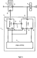
- FIG. 1 shows a block diagram of an exemplary embodiment of the device according to the invention for functional monitoring 1 in a simple design.
- FIG. 1 also shows a safety switching means 5 with an actuator 6 is switched.
- the safety switching means 5 an actuating input 10 and a switching output 11, which is in communication with the actuator 6, on.
- the function of the safety switching means 5 is to be monitored.
- the device for monitoring function 1 consists of an actuating means 2 and an evaluation means 3.
- the actuating means 2 is connected via an actuating output 9 to the actuating input 10 of the safety switching means 5.
- the actuating means 2 is used to deliver a signal via the actuating output 9 to the safety switching means 5. With the aid of this signal, the safety switching means 5 is switched when the safety switching means 5 is functioning properly. Therefore, this signal is also referred to as a switching signal.
- the actuating means 2 can deliver the switching signal, for example, in response to a signal at a control input 7 of the actuating means 2.
- the device for function monitoring 1 has a control means 4 which is connected to the actuating means 2 via the control input 7 of the actuating means 2.
- the control means 4 may for example deliver a signal to the control input 7, which causes the actuating means 2 to change the signal at the actuating output 9 such that the safety switching means 5 is switched, for example in response to a detected actuator error, such as welded relay contacts to open the safety switching means 5 and thus to disconnect the actuator 6 from the power supply.
- the actuating means 2 on a test input 8.
- the actuating means 2 the signal with the information received that a bump test is to be performed. In the embodiment shown, this is done by a signal at the test input and a simultaneous removal of the signal at the control input.
- the test input 8 of the actuating means 2 is connected to the control means 4. Via this connection, the control means 4 can control the execution of functional tests of the safety switching means 5. Function tests of the safety switching means 5 can be initiated cyclically or at irregular intervals via the test input 8. During a functional test, the actuating means 2, depending on the test signal obtained, the safety switching means 5 off and on again.
- the evaluation means 3 ensures that the functional test is terminated as quickly as possible and the operating mode is continued.
- the evaluation means 3 has a monitoring input 15, which is connected to the switching output 11 of the safety switching means 5.
- the evaluation means 3 With the help of this monitoring input 15 the evaluation means 3, the signal with the information about a change of a signal at the switching output 11 of the safety switching means 5 are provided.
- the evaluation means 3 changes the signals at the feedback output 14 and at the function reporting output 16.
- the signal with the information about the change of the signal at the switching output and thus on the respective switching state of the safety switching means 5 is provided by the evaluation 3 to the actuating means 2 via a feedback connection 12.
- the actuating means 2 can immediately reverse the signal change at the actuating output 9 and thus switch on the safety means 5 again, before the functional test is ended by the end of the test signal.
- the signal with the information about the switching state of the safety switching means 5 via aginasmeldausgang 16 of the evaluation means 3, the control means 4th made available.
- this signal is provided with this information regardless of whether the safety switching means 5 has been turned on again or not.
- the evaluation means 3 also has a control input 17 and a test input 18.
- the evaluation means 3 can distinguish between a shutdown of the safety switching means 5 due to a functional test or an intentional shutdown.
- the provision of the control input 17 and the test input 18 is only one possible implementation. There are also solutions where only one of the two inputs is necessary.
- this function can also be achieved, for example, in that the actuating means 2 is switched such that only when the functional test is displayed at the test input 8, the feedback signal can have an effect on the actuating output 9.
- the safety switching means 5 may be an electronic semiconductor switch. Alternatively, however, the safety switching means 5 can also be formed from a mechanical relay.
- the operating voltage of the actuator 6 and the operating voltage of the function monitoring device 1 is the same.
- the actuator 6 and the function monitoring device 1 could have different operating voltages.
- the switched operating voltage for the actuator 6 may be higher than the voltage of the device for functional monitoring 1.
- a means for reducing the voltage (not shown in the figures) may be arranged. This means could for example be formed by a voltage divider circuit or a transformer, each with or without voltage rectifier.
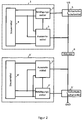
- FIG. 2 shows an embodiment of the inventive device for function monitoring 1 in redundant design.
- the security switching means 5, as well as the attached device for functional monitoring 1 executed twice.
- the control means 4 can also be implemented redundantly.
- the first safety switching means 5 switches the actuator 6 against the positive supply voltage, UB, the second safety switching means 5', the actuator 6 against the ground, GND, switches.
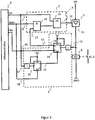
- FIG. 3 shows a realization of the in the FIGS. 1 and 2 shown actuating means 2 and evaluation means 3 by means of existing hardware components logic.
- the actuating means 2 is formed of an AND gate 21 and of an OR gate 22 with 2 inputs each.
- the control input 7 of the actuating means 2 is connected to the OR gate 22, so that a "1" signal at the control input 7, the safety switching means 5 is actuated.
- the output of the AND gate 21 is connected.
- the AND gate 21 combines the signal at the test input 8 and the feedback input 13 of the actuating means 2.
- this AND operation causes the safety switching means 5 to be switched on again immediately after a shutdown in connection with a functional test of the safety switching means 5. This happens here by the simultaneous application of a signal to the test input 8 and to the feedback input 13 of the actuating means 2.
- the signal at the feedback input 13 of the actuating means 2 is provided by the evaluation means 3.
- the function of the evaluation means 3 is to detect a shutdown during a functional test and this shutdown the control means 4 via a signal the function report output 16 and the actuating means 2 via a signal at the feedback input 13 display.
- the evaluation means 3 with 2 edge-triggered D flip-flops 19, 20 realized.
- the flip-flops 19, 20 are connected so that a signal change at the control input 7 and at the test input 8, the flip-flops 19, 20 initialized, ie the signals at the enable output 23 of the flip-flop 19 and the feedback output 14 of the flip-flop 20 are set to "0" so that they respond to "flanks" caused by the subsequent test procedure.
- a shutdown carried out by a functional test is thus registered as a signal change from "1" to "0", or from "0" to "1” by negating the flip-flop 19 connected to the monitoring input 15.
- the edge-triggered flip-flop 19 then changes the switching state at its outputs, so that the signal is set at the feedback output 14 of "0" to "1" to signal the actuator 2, the successful shutdown.
- the signal at the function reporting output 16 to which the control means 4 is connected which is shown here as a microcontroller, also changes.
- the signal at the functional signaling output 16 is stored in the memory of the microcontroller. This means that the signal is still displayed after switching on the safety switching means 5 and after the signal change to the control input 17. By the subsequent change of the signal at the test input 18, the flip-flops 19, 20 are brought back to the state before the functional test.
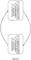
- FIG. 4a shows a state diagram for the control of the device according to the invention for functional monitoring in the embodiment, as shown in the FIG. 3 is shown in error-free operation.
- a signal at the control input 7 of the actuating means 2 the safety switching means 5 turns on and at the same time that the omission of this signal at the control input 7 of the actuating means 2, the safety switching means 5 turns off.
- FIG. 4b is a state diagram for the control of the device according to the invention for function monitoring, in the embodiment as shown in the FIG. 3 is shown when performing a functional test with reclosing and with a faultless safety switching means.
- test input 8 of the actuator 2 is set to "1" while the control input 7 is still at “1", thus turning on the safety switching means 5 in an on state to keep.
- this signal change at the test input 8 does not yet cause the safety switching means 5 to be switched off.
- the flip-flop 19 Due to the signal change at the monitoring input 15 of the evaluation means 3, caused by the switching off of the safety switching means 5, the flip-flop 19 is set, which in turn causes a signal change from "0" to "1" at the feedback input 13 of the actuating means 2. As shown in node 4, the "1" signal at the feedback input 13 of the actuating means 2, or the “1” signal at the feedback output 14 of the evaluation means 3 and the still pending test signal 8, the safety switching means 5 by a "1 "Signal at the operation input 10 is turned on again.
- Figure 4c is a state diagram for the control of the inventive device for monitoring function in the embodiment, as shown in the FIG. 3 is shown in the performance of a functional test in which the safety switching means 5 is not switched back on because of the presence of a fault.
- Fig. 5 shows a timing diagram for the control of the device according to the invention for functional monitoring 1 in the embodiments as shown in the FIGS. 1 to 3 shown in error-free operation.
- the test input 8 and the function message output 16 are in FIG. 5 for the sake of clarity, the operation input 10 and the switching output 11 of the safety switching means 5, the monitoring input 15 of the evaluation means 3 and the signal at the feedback input 13 of the actuating means 2 shown.
- FIG. 5 the implementation of a functional test is described.
- the input signal at the control input 7 is set to "1" and the input signal at the test input 8 is set to "0".
- the signal at the feedback input 13 is at "0".
- the function message signal at the function message output 16 is at "1" and the safety switching means 5 is closed.
- the state of the signals shown at time t 0 represents the normal operation.
- the connected actuator 6 is supplied with voltage.
- the software in the control means 4 permanently monitors the normal operation via the function reporting output 16, ie it checks the actual value at the safety switching means 5 with regard to deviations from the setpoint value at the control input 7.
- the functional test of the safety switching means 5 is prepared by the software in the control means 4. The preparation is done by setting test input 8 to "1". However, this does not start the actual function test.
- the safety switching means 5 is further controlled in accordance with the desired value at the actuating output 9 of the actuating means 2 and the connected actuator 6 is supplied with voltage.
- the preparation causes the actuating means 2 and the evaluation means 3 to be realized with flip-flops 19, 20, as shown in FIG. 3 is shown to respond to "flanks" caused by the test procedure described below.
- the actual functional test of the safety switching means 5 is started.
- the software in the control means 4 switches the setpoint at the control input 7 of the actuating means 2 from “1" to “0” and the actuating means 2 reacts by switching off the safety switching means 5 by setting the actuating input 10 of the safety switching means 5 to "0".
- the evaluation means 3 monitors the output level on the actuator 6, or on the safety switching means 5 through the monitoring input 15th
- the evaluation means 3 notes at this time that the safety switching means 5 has been switched off and reacts immediately with a "1" signal at the feedback input 13.
- the signal at the feedback input 13 is supplied to the actuating means 2, thereby initiating the reconnection of the safety switching means 5 by the actuating means 2 in that the signal at the operating input 10 of the safety switching means 5 is reset to 1.
- the control input 7 is still at "0".
- the actuator 6 By switching on again, the actuator 6 is supplied with voltage again. Since the evaluation means 3 automatically reacts to the successful functional test and the safety switching means 5 turns on again, the functional test for the connected actuator 6 is kept as short as possible.
- control means 4 has read in the signal at the function reporting output 16 of the evaluation means 3 and recognized the successfully performed function test and the signal at the control input 7 of the actuating means 2 is set by the control means 4 again from “0" to "1".
- the inputs and outputs again have the same states as before the execution of the function test.
- the control means 4 again controls the control input 7 of the actuating means 2.
- the signals in the in FIG. 5 shown and described above pulse diagram for driving the device according to the invention for functional monitoring 1 can also assume other states depending on the implementation with logical components at the various times shown. For example, all the signal states shown could be inverted.
Description
Die vorliegende Erfindung betrifft eine Vorrichtung und ein Verfahren zur Funktionsüberwachung eines Sicherheitsschaltmittels, wobei das Sicherheitsschaltmittel insbesondere zum Schalten eines Aktuators verwendet werden kann.The present invention relates to a device and a method for monitoring the operation of a safety switching means, wherein the safety switching means can be used in particular for switching an actuator.
Sicherheitsschaltungen mit Sicherheitsschaltmitteln kommen für das Schalten von sicherheitsrelevanten Aktuatoren zum Einsatz, wie beispielsweise einem Antriebsmotor, der über ein Motorschütz geschaltet wird.
Die Funktionsfähigkeit des Sicherheitsschaltmittels ist daher zu jedem Zeitpunkt sicherzustellen. Bevorzugt finden Halbleiterschalter als Sicherheitsschaltmittel Verwendung, weil dadurch der Einsatz von Metallkontakten, die sich abnutzen, oxidieren oder auch verkleben können, vermieden werden kann. Für das Testen der Funktionsfähigkeit wird der Schaltzustand des Sicherheitsschaltmittels in regelmäßigen Zeitabständen geändert, um das einwandfreie Schalten des Sicherheitsschaltmittels überprüfen zu können. Nachdem die einwandfreie Funktionsfähigkeit des Sicherheitsschaltmittels festgestellt wurde, wird die Änderung des Schaltzustands des Sicherheitsschaltmittels wieder rückgängig gemacht. Der zeitliche Abstand zwischen den zwei Schaltvorgängen sollte relativ kurz sein. Auf jeden Fall muss der zeitliche Abstand so kurz sein, dass aufgrund der Trägheit des Aktuators der Betriebszustand des Aktuators nicht geändert wird, um ein versehentliches Abschalten des Aktuators zu verhindern.The functionality of the safety switching device must therefore be ensured at all times. Semiconductor switches are preferably used as safety switching means because this avoids the use of metal contacts which can wear out, oxidize or even stick together. For testing the operability of the switching state of the safety switching means is changed at regular intervals in order to check the proper switching of the safety switching means can. After the proper functioning of the safety switching means has been determined, the change in the switching state of the safety switching means is reversed. The time interval between the two switching operations should be relatively short. In any case, the time interval must be so short that due to the inertia of the actuator, the operating state of the actuator is not changed to prevent accidental shutdown of the actuator.
Im Stand der Technik wird üblicherweise die Funktionsüberwachung des Sicherheitsschaltmittels mittels einer programmierbaren Logik getestet, wie zum Beispiel in
Wie zum Beispiel in
In
Derartige Funktionsüberwachungen haben allerdings den Nachteil, dass die verwendeten programmierbaren Logiken, wie beispielsweise Mikrocontroller oder Recheneinheiten hinreichend schnell sein müssen, um die erfolgreiche Änderung des Schaltzustands an dem entsprechenden Eingang der programmierbaren Logik erkennen zu können, da das zugehörige Signal dort nur für eine kurze Dauer anliegt. Daher können ausschließlich sehr hochgetaktete programmierbare Logiken für die Funktionsüberwachung verwendet werden, da nur diese programmierbaren Logiken den Geschwindigkeitsanforderungen entsprechen. Allerdings sind solche programmierbaren Logiken vergleichsweise teuer. Weiterhin haben derartige Funktionsüberwachungen den Nachteil, dass die Abschaltzeit von der Geschwindigkeit und Softwarearchitektur der programmierbaren Logik abhängt und die Dauer des Testsignals bzw. des Testimpulses gegebenenfalls manuell an die Trägheit der zu schaltenden Komponente angepasst werden muss.However, such function monitoring systems have the disadvantage that the programmable logic systems used, such as microcontrollers or arithmetic units, must be sufficiently fast to be able to detect the successful change of the switching state at the corresponding input of the programmable logic since the associated signal there is only for a short duration is applied. Therefore, only very high-speed programmable logics can be used for the function monitoring, since only these programmable logics meet the speed requirements. However, such programmable logic is comparatively expensive. Furthermore, such function monitors have the disadvantage that the turn-off time depends on the speed and software architecture of the programmable logic and the duration of the test signal or the test pulse may need to be manually adjusted to the inertia of the component to be switched.
Die Aufgabe der vorliegenden Erfindung ist daher, eine Vorrichtung zur Funktionsüberwachung eines Sicherheitsschaltmittels bereitzustellen, die günstig in der Herstellung ist, unabhängig von der Geschwindigkeit der programmierbaren Logik ist und die unabhängig von der Trägheit der zu schaltenden Komponente ein verlässliches Ergebnis liefert.The object of the present invention is therefore to provide a device for monitoring the operation of a safety switching means, which is inexpensive to manufacture, independent of the speed of the programmable logic and which provides a reliable result regardless of the inertia of the component to be switched.
Diese Aufgabe wird erfindungsgemäß durch die Vorrichtung zur Funktionsüberwachung gemäß Anspruch 1 und das Verfahren zur Funktionsüberwachung gemäß Anspruch 15 gelöst.This object is achieved by the device for monitoring function according to
Die erfindungsgemäße Vorrichtung wird zur Funktionsüberwachung eines Sicherheitsschaltmittels verwendet, welches insbesondere zum Schalten eines Aktuators verwendet werden kann. Ein derartiges Sicherheitsschaltmittel weist einen Betätigungseingang und einen Schaltausgang auf. Die erfindungsgemäße Vorrichtung weist ein Betätigungsmittel und ein Auswertemittel auf. Das Betätigungsmittel weist einen Steuereingang, einen Testeingang, einen Rückmeldungseingang und einen Betätigungsausgang zur Verbindung mit dem Betätigungseingang des Sicherheitsschaltmittels auf. Das Auswertemittel weist einen Überwachungseingang zur Verbindung mit dem Schaltausgang des Sicherheitsschaltmittels, einen Funktionsmeldeausgang und einen Rückmeldungsausgang auf. Das Betätigungsmittel ist derart ausgestaltet, dass es für einen Funktionstest des Sicherheitsschaltmittels ein Signal an dem Betätigungsausgang in Abhängigkeit von den Signalen an dem Testeingang und dem Steuereingang ändert. Das Auswertemittel ist derart ausgestaltet, dass es über den Überwachungseingang eine Änderung eines Signals an dem Schaltausgang des Sicherheitsschaltmittels erkennt und insbesondere bei einem Funktionstest ein Signal mit einer Information über die Änderung über den Rückmeldungsausgang des Auswertemittels an den Rückmeldungseingang des Betätigungsmittels weiterleitet und ein Signal mit einer Information über die Änderung an dem Funktionsmeldeausgang bereitstellt. Außerdem ist das Betätigungsmittel derart ausgestaltet, dass bei einem Funktionstest im Falle des Erhalts eines Signals mit einer Information über die Änderung des Signals an dem Schaltausgang des Sicherheitsschaltmittels, umgehend die Signaländerung an dem Betätigungsausgang rückgängig gemacht wird.The device according to the invention is used for monitoring the function of a safety switching means, which can be used in particular for switching an actuator. Such a safety switching means has an operating input and a switching output. The device according to the invention has an actuating means and an evaluation means. The actuating means has a control input, a test input, a feedback input and an actuating output for connection to the operating input of the safety switching means. The evaluation device has a monitoring input for connection to the switching output of the safety switching device, a function message output and a feedback output. The actuating means is configured to change a signal at the actuation output in response to the signals at the test input and the control input for a functional test of the safety switching means. The evaluation means is configured in such a way that it detects a change in a signal at the switching output of the safety switching means via the monitoring input and, in particular during a functional test, forwards a signal with information about the change via the feedback output of the evaluation means to the feedback input of the actuating means Provides signal with information about the change in the function message output. In addition, the actuating means is designed such that in a functional test in the case of obtaining a signal with information about the change of the signal at the switching output of the safety switching means, immediately reversing the signal change at the actuating output.
Mit Hilfe dieser erfindungsgemäßen Vorrichtung kann die Funktion von Sicherheitsschaltmitteln erstmals zuverlässig und günstig überwacht werden. Darüber hinaus stellt die erfindungsgemäße Vorrichtung erstmals eine universell einsetzbare Funktionsüberwachung bereit, da die Vorrichtung unabhängig von der zu schaltenden Komponente eingesetzt werden kann.With the aid of this device according to the invention, the function of safety switching means can be reliably and conveniently monitored for the first time. In addition, the device according to the invention provides for the first time a universally applicable function monitoring, since the device can be used independently of the component to be switched.
Die erfindungsgemäße Vorrichtung wird beispielhaft im Zusammenhang mit einem Sicherheitsschaltmittel zum Schalten eines Aktuators beschrieben. Die gleichen Vorteile können aber auch bei Schalten anderer Elemente erzielt werden.The device according to the invention is described by way of example in connection with a safety switching means for switching an actuator. The same advantages can also be achieved when switching other elements.
Derartige Sicherheitsschaltmittel weisen einen Betätigungseingang und einen Schaltausgang auf. Der Betätigungseingang ist der Eingang des Sicherheitsschaltmittels über den das Sicherheitsschaltmittel ein Signal mit der Information erhält, dass es schalten soll. Im Rahmen der Erfindung beschreibt ein Signal etwas mit dem eine Information übermittelt werden kann. Die Information kann beispielsweise durch ein analoges oder ein digitales Signal übermittelt werden. Die Information kann auch dadurch übermittelt werden, dass entweder ein Signal oder kein Signal übermittelt wird. Der Schaltzustand des Sicherheitsschaltmittels wirkt sich auf den Schaltausgang des Sicherheitsschaltmittels aus. Beispielsweise kann das Sicherheitsschaltmittel noch einen weiteren Eingang aufweisen, an dem eine Betriebsspannung anliegt. In Abhängigkeit von dem Schaltzustand des Sicherheitsschaltmittels liegt diese Betriebsspannung an dem Schaltausgang und somit auch an dem mit dem Schaltausgang verbundenen Aktuator an oder nicht.Such safety switching means have an actuating input and a switching output. The actuation input is the input of the safety switching means via which the safety switching means receives a signal with the information that it should switch. In the context of the invention, a signal describes something with which information can be transmitted. The information can be transmitted, for example, by an analog or a digital signal. The information can also be transmitted by transmitting either a signal or no signal. The switching state of the safety switching means affects the switching output of the safety switching means. For example, the safety switching means may have another input to which an operating voltage is applied. Depending on the switching state of the safety switching means, this operating voltage is applied to the switching output and thus also to the actuator connected to the switching output or not.
Das Betätigungsmittel der erfindungsgemäßen Vorrichtung weist einen Testeingang auf. Hierbei handelt es sich um einen Eingang über den das Betätigungsmittel ein Signal mit einer Information über beziehungsweise für den Funktionstest erhält. Ein an diesem Eingang anliegendes Signal kann beispielsweise anzeigen, dass bei einer fallenden Flanke am Steuereingang ein Funktionstest durchgeführt werden soll. Das Betätigungsmittel weist außerdem einen Betätigungsausgang auf. Dieser Betätigungsausgang steht während der Funktionsüberwachung in Verbindung mit dem Betätigungseingang des Sicherheitsschaltmittels. Mit Hilfe eines über den Betätigungsausgang bereit gestellten Signals kann das Sicherheitsschaltmittel betätigt werden, d.h. es kann geschaltet werden. Darüber hinaus weist das Betätigungsmittel noch einen Rückmeldungseingang auf, der weiter unten erläutert wird.The actuating means of the device according to the invention has a test input. This is an input via which the actuating means receives a signal with information about or for the functional test. For example, a signal present at this input can indicate that a function test is to be performed on a falling edge at the control input. The actuating means also has an actuating output. This control output is in communication with the operation input of the safety switching means during the function monitoring. By means of a signal provided via the actuating output, the safety switching means can be actuated, i. it can be switched. In addition, the actuating means still has a feedback input, which will be explained below.
Im Rahmen der Funktionsüberwachung kann mittels des Betätigungsmittels der erfindungsgemäßen Vorrichtung ein Signal an dem Betätigungsausgang verändert werden. Der Zweck dieser Signaländerung ist es für einen Funktionstest den Schaltzustand des Sicherheitsschaltmittels, das über seinen Betätigungseingang mit dem Betätigungsausgang des Betätigungsmittels verbunden ist, zu verändern. Erfindungsgemäß ändert das Betätigungsmittel das Signal an dem Betätigungsausgang in Abhängigkeit von einer Änderung der Signale an dem Steuereingang und dem Testeingang. Wie bereits oben erläutert, kann es sich bei dem Signal an dem Testeingang beispielsweise um ein Signal handeln, das die Durchführung eines Funktionstests anzeigt. Beispielsweise wird zunächst als Vorbereitung für den Test das Signal an dem Testeingang geändert. Danach wird der Test durch eine Änderung des Signals an dem Steuereingang eingeleitet.As part of the function monitoring, a signal at the actuating output can be changed by means of the actuating means of the device according to the invention. The purpose of this signal change is to change the switching state of the safety switching means which is connected via its actuating input to the actuating output of the actuating means for a functional test. According to the invention, the actuating means changes the signal at the actuating output in response to a change in the signals at the control input and the test input. As already explained above, the signal at the test input may, for example, be a signal indicating the execution of a functional test. For example, the signal at the test input is first changed to prepare for the test. Thereafter, the test is initiated by a change in the signal at the control input.
Ein Beispiel für die Änderung eines Signals ist der Wechsel von einem logischen Low-Pegel zu einem logischen High-Pegel oder andersherum. Der Low-Pegel kann auch als logisches "0" Signal bezeichnet werden und der High-Pegel als logisches "1" Signal. Grundsätzlich ist aber jede Signaländerung umfasst, die von dem Empfänger als Änderung erkannt werden kann. Insbesondere sind Signaländerungen umfasst, durch die sich die von dem Signal übermittelte Information ändert.An example of changing a signal is the change from a logical low level to a logical high level or vice versa. The low level can also be referred to as a logic "0" signal and the high level as a logical "1" signal. In principle, however, any signal change is included that can be recognized as a change by the receiver. In particular, signal changes are included, by which the information transmitted by the signal changes.
Das Auswertemittel der erfindungsgemäßen Vorrichtung weist einen Überwachungseingang zur Verbindung mit dem Schaltausgang des Sicherheitsschaltmittels auf. Außerdem weist das Auswertemittel einem Funktionsmeldeausgang und einem Rückmeldungsausgang auf.The evaluation means of the device according to the invention has a monitoring input for connection to the switching output of the safety switching means. In addition, the evaluation means has a function message output and a feedback output.
Der Überwachungseingang des Auswertemittels erkennt eine Änderung eines Signals an dem Schaltausgang des Sicherheitsschaltmittels. Hierfür kann der Überwachungseingang beispielsweise an der Verbindung zwischen dem Sicherheitsschaltmittel und dem Aktuator angeschlossen sein.The monitoring input of the evaluation means detects a change of a signal at the switching output of the safety switching means. For this purpose, the monitoring input may be connected, for example, to the connection between the safety switching means and the actuator.
Der Rückmeldungsausgang des Auswertemittels steht über eine Rückmeldungsverbindung in Verbindung mit dem Rückmeldungseingang des Betätigungsmittels. Im Rahmen der Erfindung stellt das Auswertemittel dem Betätigungsmittel über diese Verbindung ein Signal mit einer Information über die Änderung eines Signals an dem Schaltausgang des Sicherheitsmittels bereit. Dies hat den Vorteil, dass das Betätigungsmittel sofort nach einer erkannten Schaltzustandsänderung des Sicherheitsschaltmittels, den Schaltzustand wieder ändern kann. Das Signal mit der Information über die Änderung des Signals an dem Schaltausgang des Sicherheitsschaltmittels kann auf viele verschiedene Arten an den Rückmeldungseingang des Betätigungsmittels übermittelt werden. Vorzugsweise ändert sich ein Signal an dem Rückmeldungseingang des Betätigungsmittels, wenn eine Änderung des Signals an dem Schaltausgang des Sicherheitsschaltmittels festgestellt wurde.The feedback output of the evaluation means is connected via a feedback connection in conjunction with the feedback input of the actuating means. In the context of the invention, the evaluation means provides the actuation means via this connection a signal with information about the change of a signal at the switching output of the safety means. This has the advantage that the actuating means can change the switching state again immediately after a detected switching state change of the safety switching means. The signal with the information about the change of the signal at the switching output of the safety switching means can be transmitted in many different ways to the feedback input of the actuating means. Preferably, a signal changes at the feedback input of the actuator when a change in the signal at the switching output of the safety switching means has been detected.
Über den Funktionsmeldeausgang stellt das Auswertemittel auch ein Signal mit einer Information über die Änderung des Signals an dem Schaltausgang bereit. Hierbei kann es sich beispielsweise um eine Anzeige handeln, dass das Sicherheitsschaltmittel ordnungsgemäß funktioniert. Dieses Signal mit dieser Information kann aber auch an andere Mittel weitergeleitet werden, wie weiter unten beschrieben wird.The evaluation means also provides a signal with information about the change of the signal at the switching output via the functional message output. This may be, for example, an indication that the safety switching means is functioning properly. However, this signal with this information can also be forwarded to other means, as described below.
Grundsätzlich kann das Sicherheitsschaltmittel den Energieversorgungseingang des Aktuators gegen die positive Versorgungsspannung und/oder den Energieversorgungsausgang des Aktuators gegen Masse schalten. In einer bevorzugten Ausführungsform kann das Sicherheitsschaltmittel den Aktuator sowohl gegen die positive Versorgungsspannung als auch gegen die Masse schalten. Beispielsweise kann die erfindungsgemäße Funktionsüberwachung redundant aufgebaut sein, d.h. mit Hilfe von zwei Sicherheitsschaltern wird ein Aktuator gegen die Versorgungsspannung und gegen Masse geschaltet, wie es beispielsweise in der Norm EN ISO 13849 für Sicherheitsschaltanordnungen der höchsten Sicherheitsstufe verlangt wird.Basically, the safety switching means the power supply input of the actuator against the positive supply voltage and / or switch the power supply output of the actuator to ground. In a preferred embodiment, the safety switching means can switch the actuator both against the positive supply voltage and against the ground. For example, the function monitoring according to the invention can be constructed redundantly, ie with the help of two safety switches, an actuator is switched against the supply voltage and ground, as required for example in the standard EN ISO 13849 for safety switching devices of the highest level of security.
In einer weiteren bevorzugten Ausführungsform ist das Sicherheitsschaltmittel ein Halbleiterschalter. Halbleiterschalter haben im Gegensatz zu mechanischen Relais keine mechanischen Kontakte und schnellere Schaltzeiten. Weiterhin unterliegen Halbleiterschalter einer geringeren Alterung als vergleichbare Schalter mit mechanischen Kontakten. Im Rahmen der vorliegenden Erfindung könnte allerdings auch ein Relais als Sicherheitsschaltmittel verwendet werden, zum Beispiel wenn die Verwendung eines Relais von einer Norm für die Funktionsüberwachung des Sicherheitsschaltmittels vorgeschrieben ist.In a further preferred embodiment, the safety switching means is a semiconductor switch. Semiconductor switches, in contrast to mechanical relays, have no mechanical contacts and faster switching times. Furthermore, semiconductor switches are subject to less aging than comparable switches with mechanical contacts. In the context of the present invention, however, a relay could also be used as a safety switching means, for example if the use of a relay is prescribed by a standard for monitoring the operation of the safety switching means.
In einer bevorzugten Ausführungsform ist das Betätigungsmittel ausgestaltet das Signal am Betätigungsausgang so lange zu ändern, wie sich das Signal an dem Testeingang und das Signal an dem Rückmeldungseingang des Betätigungsmittels nicht ändern. Durch das Ändern des Signals an dem Betätigungsausgang wird der Zustand des Sicherheitsschaltmittel geändert. Um sicherzugehen, dass für den Funktionstest dieser geänderte Zustand des Sicherheitsschaltmittels lang genug besteht, wird der Zustand erst geändert, wenn über den Rückmeldungseingang ein erfolgreicher Funktionstest gemeldet wird oder über den Testeingang der Funktionstest beendet wird. Durch diese einfache logische Bedingung kann die Zeit für eine Testabschaltung auf ein Minimum begrenzt werden. Nach einer durch das Auswertemittel erkannten Abschaltung des Sicherheitsschaltmittels, ändert das Auswertemittel das Signal auf der Rückmeldungsverbindung. Somit wird durch die Änderung des Signals die Änderung an dem Signal an dem Betätigungsausgang des Betätigungsmittels wieder rückgängig gemacht und somit das Sicherheitsschaltmittel beispielsweise wieder eingeschaltet.In a preferred embodiment, the actuation means is configured to change the signal at the actuation output as long as the signal at the test input and the signal at the feedback input of the actuation means do not change. By changing the signal at the actuation output, the state of the safety switching means is changed. To ensure that this changed state of the safety switching device persists long enough for the function test, the state is only changed if a successful function test is reported via the feedback input or the functional test is ended via the test input. This simple logic condition can minimize the time for a test shutdown. After a detection of the safety switching means detected by the evaluation means, the evaluation means changes the signal on the feedback connection. Thus, by changing the signal, the change in the signal at the actuating output of the Actuating reversed and thus the safety switching means, for example, turned on again.
Somit schaltet das Betätigungsmittel das Sicherheitsschaltmittel wieder ein, bevor sich der Schaltzustand des Aktuators verändern kann. Vorteilhaft wird durch die kurze Testabschaltung beziehungsweise die kurze Schaltzustandsänderung des Sicherheitsschaltmittels ermöglicht, dass sich der Schaltzustand des Aktuators nicht ändert. Dies ist der Fall, da der Aktuator im Allgemeinen eine gewisse Trägheit aufweist. Diese Trägheit entsteht beispielsweise durch die bewegbaren Teile eines mechanischen Relais und durch die Selbstinduktion einer verwendeten Spule.Thus, the actuating means switches the safety switching means back on before the switching state of the actuator can change. The short test shutdown or the short switching state change of the safety switching means advantageously makes it possible that the switching state of the actuator does not change. This is the case since the actuator generally has some inertia. This inertia is caused for example by the movable parts of a mechanical relay and by the self-induction of a coil used.
In noch einer weiteren bevorzugten Ausführungsform wird das Signal mit der Information über die Änderung des Signals an dem Schaltausgang an dem Funktionsmeldeausgang mindestens so lange bereitgestellt, wie ein Signal an dem Testeingang des Auswertemittels anliegt. Daher weist das Auswertemittel in einer bevorzugten Ausführungsform auch einen Testeingang auf, zum Beispiel ist dieser Testeingang mit dem Testeingang des Betätigungsmittels verbunden. Dies hat den Vorteil, dass das Auswertemittel die detektierte Schaltzustandsänderung auch noch nachdem sich der Schaltzustand des Sicherheitsschaltmittels wieder geändert hat an dem Funktionsmeldeausgang bereitstellen kann. Diese speichernde Bereitstellung hat den Vorteil, dass der Erfolg der Testabschaltung zur Funktionsüberwachung durch ein Signal an dem Funktionsmeldeausgang des Auswertemittels gemeldet wird, selbst auch dann noch, wenn der Schaltzustand des Sicherheitsmittels von dem Betätigungsmittel nach erfolgreicher Testabschaltung wieder verändert wurde. Dies ermöglicht es, die Betriebsspannung des Aktuators nur für eine sehr kurze Zeit, unabhängig von der Dauer eines Testsignals zu unterbrechen. Somit kann die Dauer des Testsignals länger als die Trägheit der Spule sein, so dass auch beispielsweise eine langsame programmierbare Logik, wie beispielsweise ein langsamer Mikrocontroller, die Schaltzustandsänderung an dem Funktionsmeldeausgang erkennen kann. Ein weitere Vorteil ist, dass dadurch auch die Anpassung der Testimpulsdauer an die Trägheit des Aktuators, beispielsweise an die Trägheit einer Spule, entfällt.In yet another preferred embodiment, the signal having the information about the change of the signal at the switching output is provided to the functional reporting output at least as long as a signal is applied to the test input of the evaluation means. Therefore, in a preferred embodiment, the evaluation means also has a test input, for example, this test input is connected to the test input of the actuating means. This has the advantage that the evaluation means can provide the detected switching state change even after the switching state of the safety switching means has changed again at the functional reporting output. This storing provision has the advantage that the success of the test shutdown for function monitoring is signaled by a signal at the functional reporting output of the evaluation means, even if the switching state of the safety means was changed again by the actuating means after a successful test shutdown. This makes it possible to interrupt the operating voltage of the actuator only for a very short time, regardless of the duration of a test signal. Thus, the duration of the test signal may be longer than the inertia of the coil, so that, for example, a slow programmable logic, such as a slow microcontroller, can detect the switching state change on the functional reporting output. Another advantage is that it also adjusts the test pulse duration to the inertia of the actuator, for example, to the inertia of a coil deleted.
In einer weiteren bevorzugten Ausführungsform ist das Betätigungsmittel ausgestaltet das Signal am Schaltausgang des Sicherheitsschaltmittels als Reaktion auf ein Signal an dem Steuereingang zu verändern. Mit Hilfe des Signals an dem Steuereingang kann das Sicherheitsschaltmittel beispielsweise in einem sogenannten Betriebsmodus geschaltet werden. Mit Betriebsmodus ist der Modus gemeint, in dem das Sicherheitsschaltmittel gewollt und für einen längeren Zeitraum geschaltet wird und nicht für den Funktionstest. Dadurch dass dieses Signal dem Betätigungsmittel bereitgestellt wird, kann das Schalten des Sicherheitsschaltmittels immer mit Hilfe des Betätigungsmittels durchgeführt werden, d.h. unabhängig davon, ob ein Funktionstest durchgeführt wird, oder ob das Schalten im Betriebsmodus stattfinden soll. Darüber hinaus kann das Signal mit der Information über das Signal am Steuereingang auch für das Durchführen des Funktionstest hilfreich sein. Beispielsweise kann das Betätigungsmittel das Durchführen eines Funktionstests verhindern, wenn sich aus dem Signal am Steuereingang ergibt, dass das Sicherheitsschaltmittel gerade im Betriebsmodus geschaltet wird.In a further preferred embodiment, the actuating means is configured to change the signal at the switching output of the safety switching means in response to a signal at the control input. With the help of the signal at the control input, the safety switching means can be switched for example in a so-called operating mode. By operating mode is meant the mode in which the safety switching means is wanted and switched for a longer period of time and not for the functional test. By providing this signal to the actuating means, the switching of the safety switching means can always be carried out by means of the actuating means, i. regardless of whether a bump test is performed, or whether switching should take place in operating mode. In addition, the signal with the information on the signal at the control input can also be helpful for performing the function test. For example, the actuating means may prevent the performance of a functional test if it results from the signal at the control input that the safety switching means is currently being switched in the operating mode.
In noch einer weiteren bevorzugten Ausführungsform weist das Auswertemittel einen Steuereingang auf, und ist ausgestaltet im Falle des Erhalts eines Signals mit einer Information über die aktuelle Schaltzustandsänderung des Sicherheitsschaltmittels als Reaktion auf ein Signal am Steuereingang das Signal am Rückmeldungsausgang und Funktionsmeldeausgang zurückzusetzen. Beispielsweise geschieht dies durch eine Änderung der Signale, die an den jeweiligen Ausgängen anstehen. Dies ermöglicht es, einer angeschlossenen Einrichtung, wie beispielsweise einem Steuermittel, zwischen einer regulären Abschaltung über ein Signal an dem Steuereingang und einer Testabschaltung über ein Signal an dem Testeingang zu unterscheiden.In yet another preferred embodiment, the evaluation means has a control input, and is configured to reset the signal at the feedback output and the function message output in the event of receiving a signal with information about the current switching state change of the safety switching means in response to a signal at the control input. For example, this is done by changing the signals that are present at the respective outputs. This allows a connected device, such as a control means, to be distinguished between a regular shutdown via a signal at the control input and a test shutdown via a signal at the test input.
In noch einer weiteren bevorzugten Ausführungsform sind die von dem Betätigungsmittel und dem Auswertemittel in den jeweiligen Ausführungsformen ausgeführten Funktionsweisen mit fest verdrahteter Logik realisiert. Dies ermöglicht ein unmittelbares Wiedereinschalten im Falle eines erfolgreichen Funktionstests des Sicherheitsschaltmittels ohne die Notwendigkeit teure Hardwarekomponenten zu verwenden. Insbesondere wird durch eine Trennung der Elemente, die das Wiedereinschalten verursachen von den Elementen, die den Funktionstest starten und das Ergebnis verarbeiten, die Verwendung von günstigen programmierbaren Logiken, wie zum Beispiel günstigen Mikrocontrollern möglich, ohne dass dadurch der Betrieb des Aktuator beeinflusst würde.In yet another preferred embodiment, the hard-wired logic operations performed by the actuating means and the evaluation means in the respective embodiments are realized. This allows for immediate reconnection in the event of a successful safety switch function test without the need to use expensive hardware components. In particular, by separating the elements causing the reclosing from the elements that start the bump test and process the result, the use of inexpensive programmable logic such as cheap microcontrollers becomes possible without affecting the operation of the actuator.
In einer weiteren bevorzugten Ausführungsform ist das Betätigungsmittel mit logischen Gattern realisiert und das Auswertemittel mit bistabilen Kippgliedern. Das Auswertemittel beinhaltet hierfür mindestens ein bistabiles Kippglied, wie beispielsweise ein Flip-Flop. Mit Hilfe des bistabilen Kippglieds kann zum Beispiel ein Signal mit der Information über die Änderung des Signals an dem Schaltausgang für einen längeren Zeitraum bereitgestellt werden, selbst wenn sich der zugehörige Schaltzustand des Sicherheitsschaltmittels zwischenzeitlich wieder geändert hat.In a further preferred embodiment, the actuating means is realized with logic gates and the evaluation means with bistable flip-flops. The evaluation means for this purpose includes at least one bistable flip-flop, such as a flip-flop. With the aid of the bistable flip-flop, for example, a signal with the information about the change of the signal at the switching output can be provided for a longer period, even if the associated switching state of the safety switching means has in the meantime changed again.
Die logischen Gatter in dem Betätigungsmittel, wie beispielsweise ein UND-Gatter und ein ODER-Gatter haben den Vorteil, dass die Verzögerung einer Logik, die lediglich aus solchen logischen Gattern aufgebaut ist, sehr gering ist und somit ein sehr schnelles Wiedereinschalten nach einer Testabschaltung ermöglicht wird. Tatsächlich werden Verzögerungen lediglich durch die unterschiedlichen Signallaufzeiten und durch die unterschiedlichen Reaktionszeiten der einzelnen logischen Gatter verursacht. Diese Verzögerungen bewegen sich lediglich im Bereich von Nanosekunden und können in der Praxis für einen Großteil der Anwendungen vernachlässigt werden.The logic gates in the actuator, such as an AND gate and an OR gate, have the advantage that the delay of a logic composed only of such logic gates is very low, thus enabling a very fast restart after a test shutdown becomes. In fact, delays are caused only by the different signal propagation times and by the different response times of the individual logic gates. These delays are only in the nanosecond range and can be neglected in practice for a majority of applications.
In noch einer weiteren bevorzugten Ausführungsform weist die Vorrichtung zur Funktionsüberwachung auch ein Steuermittel auf, das mit dem Testeingang des Betätigungsmittels und mit dem Funktionsmeldeausgang des Auswertemittels verbunden ist. Dies ermöglicht ein Steuern des Funktionstests und ein Auswerten der dadurch erhaltenen Ergebnisse durch das Steuermittel. In einer bevorzugten Ausführungsform ist das Steuermittel auch mit dem Steuereingang des Betätigungsmittels verbunden. Dadurch kann das komplette Schalten des Sicherheitsschaltmittels unabhängig davon, ob dieses Schalten im Betriebsmodus oder während einem Funktionstest stattfindet, von dem Steuermittel vorgenommen werden.In yet another preferred embodiment, the device for monitoring the function also has a control means which is connected to the test input of the actuating means and to the functional reporting output of the evaluation means. This allows controlling the functional test and evaluating the results obtained thereby by the control means. In a preferred embodiment, the control means is also connected to the control input of the actuating means. Thereby, the complete switching of the safety switching means, regardless of whether this switching takes place in the operating mode or during a functional test, be made by the control means.
In einer bevorzugten Ausführungsform ist das Steuermittel ausgestaltet in periodischen Intervallen einen Funktionstest zu initiieren. Mit Hilfe derartiger periodischer Tests kann sichergestellt werden, dass ein etwaiger Fehler schnell erkannt wird. In einer bevorzugten Ausführungsform initiiert das Steuermittel den Funktionstest durch eine Änderung der Signale an dem Testeingang und dem Steuereingang des Betätigungsmittels. Dadurch können die Bedingungen für das Durchführen des Funktionstests leicht geändert werden. Vorzugsweise liegt das periodische Intervall mit dem der Funktionstest initiiert wird in einem Bereich von 5 Millisekunden bis 15 Minuten. Grundsätzlich kann das periodische Intervall aber jede Länge haben, die beispielsweise von den relevanten Normen für die unterschiedlichen Anwendungen vorgeschrieben werden, bzw. ein Intervall das dem Entwickler als angemessen erscheint. Die Länge des Testimpulses kann beispielsweise 50 bis 100 µs betragen, aber abhängig von der Anwendung auch kürzer oder länger sein. Alternativ hierzu kann der Testimpuls auch länger sein, da nach einer erfolgten Testabschaltung das Sicherheitsschaltmittel sofort wieder eingeschaltet wird, unabhängig von der Dauer des Testimpulses.In a preferred embodiment, the control means is configured to initiate a bump test at periodic intervals. With the help of such periodic tests can be ensured that any error is detected quickly. In a preferred embodiment, the control means initiates the functional test by changing the signals at the test input and the control input of the actuating means. This can easily change the conditions for performing the bump test. Preferably, the periodic interval at which the functional test is initiated is in a range of 5 milliseconds to 15 minutes. In principle, however, the periodic interval may have any length prescribed, for example, by the relevant standards for the different applications, or an interval that the developer deems appropriate. The length of the test pulse may be 50 to 100 μs, for example, but may be shorter or longer depending on the application. Alternatively, the test pulse may be longer, because after a successful test shutdown, the safety switching means is immediately turned on again, regardless of the duration of the test pulse.
In einer weiteren bevorzugten Ausführungsform enthält das Steuermittel eine programmierbare Logik, wie beispielsweise einen Mikrocontroller. Mit Hilfe einer derartigen programmierbaren Logik kann das periodische Intervall und die Länge des Testimpulses, aber auch unterschiedliche Intervallzeiten oder Impulslängen leicht implementiert werden und die Ansteuerung weiterer Komponenten, wie zum Beispiel weiterer Sicherheitsschaltmittel in dem Schaltkreis vorgenommen werden.In another preferred embodiment, the control means includes programmable logic, such as a microcontroller. By means of such a programmable logic, the periodic interval and the length of the test pulse, but also different interval times or pulse lengths can be easily implemented and the control of other components, such as further safety switching means are made in the circuit.
Das erfindungsgemäße Verfahren zur Funktionsüberwachung eines Sicherheitsschaltmittels, welches insbesondere zum Schalten eines Aktuators verwendet werden kann, weist die folgenden Schritte auf: Ändern eines Signals an einem Betätigungsausgang eines Betätigungsmittels, der verbunden ist mit einem Betätigungseingang des Sicherheitsschaltmittels, in Abhängigkeit von einem Signal an einem Testeingang und einem Steuereingang des Betätigungsmittels, Erkennen an einem Auswertemittel eine Änderung eines Signals an einem Schaltausgang des Sicherheitsschaltmittels, Bereitstellen an einem Funktionsmeldeausgang des Auswertemittels ein Signal mit einer Information über die Änderung des Signals an dem Schaltausgang des Sicherheitsschaltmittels und Weiterleiten des Signals mit der Information über die Änderung an einen Rückmeldungseingang des Betätigungsmittels, und Rückgängigmachen der Signaländerung an dem Betätigungsausgang des Betätigungsmittels bei einem Funktionstest abhängig von dem Erhalt des Signals mit der Information über die Änderung.The inventive method for monitoring the operation of a safety switching means, which can be used in particular for switching an actuator, comprises the following steps: changing a signal at an actuating output of an actuating means, the connected to an actuating input of the safety switching means, in response to a signal at a test input and a control input of the actuating means, detecting at an evaluation a change of a signal at a switching output of the safety switching means, providing at a Funktionsmeldausgang the evaluation means a signal with information about the change the signal at the switching output of the safety switching means and forwarding the signal with the information about the change to a feedback input of the actuating means, and undoing the signal change at the actuating output of the actuating means in a functional test depending on the receipt of the signal with the information about the change.
Im Folgenden werden die erfindungsgemäße Vorrichtung und das erfindungsgemäße Verfahren zur Funktionsüberwachung anhand der in den nachfolgenden Figuren gezeigten Ausführungsform näher erläutert. Es zeigen:
- Fig. 1:
- ein Blockschaltbild einer beispielhaften Ausführungsform der erfindungsgemäßen Vorrichtung zur Funktionsüberwachung in einfacher Ausführung,
- Fig. 2:
- ein Blockschaltbild einer beispielhaften Ausführungsform der erfindungsgemäßen Vorrichtung zur Funktionsüberwachung in redundanter Ausführung,
- Fig. 3:
- ein vereinfachtes Schaltbild der erfindungsgemäßen Vorrichtung zur Funktionsüberwachung in dem das Betätigungsmittel und das Auswertemittel in Hardware-Logik implementiert sind,
- Fig. 4a, 4b, 4c
- Zustandsdiagramme für die Ansteuerung der erfindungsgemäßen Vorrichtung zur Funktionsüberwachung, bei einfachem Ein-und Ausschalten des Sicherheitsschaltmittels und mit einem fehlerfreien und einem fehlerhaften Sicherheitsschaltmittel, und
- Fig. 5:
- ein Impulsdiagramm der erfindungsgemäßen Vorrichtung zur Funktionsüberwachung bei der Durchführung eines Funktionstests.
- Fig. 1:
- a block diagram of an exemplary embodiment of the device according to the invention for functional monitoring in a simple design,
- Fig. 2:
- FIG. 2 shows a block diagram of an exemplary embodiment of the redundant function monitoring device according to the invention, FIG.
- 3:
- a simplified circuit diagram of the device according to the invention for functional monitoring in which the actuating means and the evaluation means are implemented in hardware logic,
- Fig. 4a, 4b, 4c
- State diagrams for the control of the device according to the invention for function monitoring, with simple switching on and off of the safety switching means and with a faultless and a faulty safety switching means, and
- Fig. 5:
- a timing diagram of the device according to the invention for functional monitoring in the implementation of a functional test.
Die in
Im Betriebsmodus kann das Betätigungsmittel 2 das Schaltsignal beispielsweise als Reaktion auf ein Signal an einem Steuereingang 7 des Betätigungsmittels 2 abgeben. In der in
Weiterhin weist das Betätigungsmittel 2 einen Testeingang 8 auf. Über den Testeingang 8 kann das Betätigungsmittel 2 das Signal mit der Information erhalten, dass ein Funktionstest durchgeführt werden soll. In der gezeigten Ausführungsform, geschieht dies durch ein Signal an dem Testeingang und eine gleichzeitige Wegnahme des Signals an dem Steuereingang. In der in
Das Auswertemittel 3 sorgt im Rahmen des Funktionstests dafür, dass der Funktionstest schnellstmöglich beendet und der Betriebsmodus weiter geführt wird. Hierfür weist das Auswertemittel 3 einen Überwachungseingang 15 auf, der mit dem Schaltausgang 11 des Sicherheitsschaltmittels 5 verbunden ist. Mit Hilfe dieses Überwachungseingangs 15 werden dem Auswertemittel 3 das Signal mit der Information über eine Änderung eines Signals an dem Schaltausgang 11 des Sicherheitsschaltmittels 5 zur Verfügung gestellt. In Abhängigkeit von dem Signal an dem Überwachungseingang 15, ändert das Auswertemittel 3 die Signale an dem Rückmeldungsausgang 14 und an dem Funktionsmeldeausgang 16.As part of the functional test, the evaluation means 3 ensures that the functional test is terminated as quickly as possible and the operating mode is continued. For this purpose, the evaluation means 3 has a
Das Signal mit der Information über die Änderung des Signals am Schaltausgang und somit über den jeweilige Schaltzustand des Sicherheitsschaltmittels 5 wird von dem Auswertemittel 3 dem Betätigungsmittel 2 über eine Rückmeldungsverbindung 12 zur Verfügung gestellt. Aufgrund dieses Signals mit dieser Information kann das Betätigungsmittel 2 die Signaländerung an dem Betätigungsausgang 9 umgehend rückgängig machen und somit das Sicherheitsmittel 5 wieder einschalten, bevor der Funktionstest durch das Ende des Testsignals beendet ist.The signal with the information about the change of the signal at the switching output and thus on the respective switching state of the safety switching means 5 is provided by the
In der vorliegenden Ausführungsform wird das Signal mit der Information über den Schaltzustand des Sicherheitsschaltmittels 5 über einen Funktionsmeldeausgang 16 des Auswertemittels 3 dem Steuermittel 4 zur Verfügung gestellt. In der vorliegenden Ausführungsform wird dieses Signal mit dieser Information zur Verfügung gestellt, unabhängig davon, ob das Sicherheitsschaltmittel 5 wieder eingeschaltet wurde oder nicht.In the present embodiment, the signal with the information about the switching state of the safety switching means 5 via a
In der vorliegenden Ausführungsform weist das Auswertemittel 3 auch einen Steuereingang 17 und einen Testeingang 18 auf. Somit kann das Auswertemittel 3 zwischen einer Abschaltung des Sicherheitsschaltmittels 5 aufgrund eines Funktionstests oder einer gewollten Abschaltung unterscheiden. Das Bereitstellen des Steuereingangs 17 und des Testeingangs 18 ist aber nur eine mögliche Realisierung. Es gibt auch Lösungen, bei denen nur einer der beiden Eingänge notwendig ist. Darüber hinaus kann diese Funktion beispielsweise auch dadurch erzielt werden, dass das Betätigungsmittel 2 derart geschaltet ist, dass nur wenn an dem Testeingang 8 der Funktionstest angezeigt wird, das Rückmeldungssignal Auswirkung auf den Betätigungsausgang 9 haben kann.In the present embodiment, the evaluation means 3 also has a
Das Sicherheitsschaltmittel 5 kann ein elektronischer Halbleiterschalter sein. Alternativ kann das Sicherheitsschaltmittel 5 aber auch aus einem mechanischen Relais gebildet werden.The safety switching means 5 may be an electronic semiconductor switch. Alternatively, however, the safety switching means 5 can also be formed from a mechanical relay.
In der gezeigten Ausführungsform ist die Betriebsspannung des Aktuators 6 und die Betriebsspannung der Vorrichtung zur Funktionsüberwachung 1 gleich. Alternativ könnten der Aktuator 6 und die Vorrichtung zur Funktionsüberwachung 1 unterschiedliche Betriebsspannungen haben. Beispielsweise kann die geschaltete Betriebsspannung für den Aktuator 6 höher sein, als die Spannung der Vorrichtung zur Funktionsüberwachung 1. In diesem Fall kann zusätzlich vor dem Überwachungseingang 15 des Auswertemittels 3 ein Mittel zur Herabsetzung der Spannung (nicht in den Figuren gezeigt) angeordnet sein. Dieses Mittel könnte beispielsweise durch eine Spannungsteiler-Schaltung oder einen Transformator, jeweils mit oder ohne Spannungsgleichrichter, gebildet werden.In the embodiment shown, the operating voltage of the
Die
In der in
In der in
Das Signal an dem Rückmeldungseingang 13 des Betätigungsmittels 2 wird von dem Auswertemittel 3 bereitgestellt. Die Funktion des Auswertemittels 3 ist eine Abschaltung im Rahmen eines Funktionstests zu erkennen und diese Abschaltung dem Steuermittel 4 über ein Signal an dem Funktionsmeldeausgang 16 und dem Betätigungsmittel 2 über ein Signal an dem Rückmeldungseingang 13 anzuzeigen.The signal at the
In der gezeigten Ausführungsform ist das Auswertemittel 3 mit 2 flankengesteuerten D-Flip-Flops 19, 20 realisiert. Wie es in der
In
Zunächst wird für die Durchführung des Funktionstests, wie es in dem Knoten 1 gezeigt ist, der Testeingang 8 des Betätigungsmittels 2 auf "1" gesetzt, während sich der Steuereingang 7 noch auf "1" befindet, um somit das Sicherheitsschaltmittel 5 in einem eingeschalteten Zustand zu halten. Dieser Signalwechsel an dem Testeingang 8 bewirkt aber noch nicht, dass das Sicherheitsschaltmittel 5 ausgeschaltet wird.First, for performing the function test, as shown in
Wie es im Knoten 2 gezeigt ist, wird durch ein Wegnehmen des Signals an dem Steuereingang 7, d.h. durch eine Änderung von "1" auf "0", der eigentliche Funktionstest durchgeführt. Diese Signaländerung bewirkt, dass das Sicherheitsschaltmittel 5 ausgeschaltet wird. Daher befindet sich auch der Betätigungseingang 10 des Sicherheitsschaltmittels 5 auf "0", wie es in dem Knoten 3 gezeigt ist.As shown in
Durch die Signaländerung am Überwachungseingang 15 des Auswertemittels 3, hervorgerufen durch das Abschalten des Sicherheitsschaltmittels 5, wird das Flip-Flop 19 gesetzt, was wiederum eine Signaländerung von "0" auf "1" am Rückmeldungseingang 13 des Betätigungsmittels 2 bewirkt. Wie es in Knoten 4 gezeigt ist, bewirkt das "1" Signal am Rückmeldungseingang 13 des Betätigungsmittels 2, bzw. das "1" Signal am Rückmeldungsausgang 14 des Auswertemittels 3 und das immer noch anstehende Testsignal 8, dass das Sicherheitsschaltmittel 5 durch ein "1" Signal an dessen Betätigungseingang 10 wieder eingeschaltet wird.Due to the signal change at the
Im Knoten 5 wird nun gezeigt, dass eine Änderung des Steuereingangs auf "1" und eine Änderung des Testeingangs auf "0" das Sicherheitsschaltmittel 5 weiter in einem eingeschalteten Zustand halten, wobei beide Flip-Flops 19, 20 für die Durchführung eines weiteren Funktionstests zurückgesetzt werden, das bedeutet, dass die Signale am Freigabeausgang 23 und am Rückmeldungsausgang 14 auf "0" gesetzt werden.In
In
Zunächst wird, wie es bezüglich Knoten 1 und 2 in
In
Im Zeitpunkt t1 wird der Funktionstest des Sicherheitsschaltmittels 5 von der Software im Steuermittel 4 vorbereitet. Die Vorbereitung erfolgt durch das auf "1" Setzen des Testeingangs 8. Der eigentliche Funktionstest wird aber dadurch noch nicht gestartet. Das Sicherheitsschaltmittel 5 wird entsprechend des Sollwertes am Betätigungsausgang 9 des Betätigungsmittels 2 weiterhin angesteuert und der angeschlossene Aktuator 6 mit Spannung versorgt.At time t 1 , the functional test of the safety switching means 5 is prepared by the software in the control means 4. The preparation is done by setting
In der gezeigten Ausführungsform bewirkt die Vorbereitung, dass das Betätigungsmittel 2 und das Auswertemittel 3 wegen der Realisierung mit Flip-Flops 19, 20, wie es in
Im Zeitpunkt t2 wird der eigentliche Funktionstest des Sicherheitsschaltmittels 5 gestartet. Die Software im Steuermittel 4 schaltet den Sollwert am Steuereingang 7 des Betätigungsmittels 2 von "1" auf "0" und das Betätigungsmittel 2 reagiert mit einem Abschalten des Sicherheitsschaltmittels 5, indem der Betätigungseingang 10 des Sicherheitsschaltmittels 5 auf "0" gesetzt wird. Das Auswertemittel 3 überwacht den Ausgangspegel am Aktuator 6, bzw. an dem Sicherheitsschaltmittel 5 durch den Überwachungseingang 15.At time t 2 , the actual functional test of the safety switching means 5 is started. The software in the control means 4 switches the setpoint at the
Mit einer Verzögerung, die durch den Spannungsverlauf am Aktuator 6 bestimmt wird, unterschreitet die Spannung am Überwachungseingang 15 im Zeitpunkt t3 den Schwellwert, ab dem das Auswertemittel 3 ein Abschalten des Aktuators 6 erkennt. Die Verzögerung ist in
Durch das Wiedereinschalten wird der Aktuator 6 wieder mit Spannung versorgt. Da das Auswertemittel 3 automatisch auf den erfolgreichen Funktionstest reagiert und das Sicherheitsschaltmittel 5 wieder einschaltet, wird der Funktionstest für den angeschlossenen Aktuator 6 so kurz wie möglich gehalten.By switching on again, the
Im Zeitpunkt t4 hat das Steuermittel 4 das Signal am Funktionsmeldeausgang 16 des Auswertemittels 3 eingelesen und den erfolgreich durchgeführten Funktionstest erkannt und das Signal am Steuereingang 7 des Betätigungsmittels 2 wird von dem Steuermittel 4 wieder von "0" auf "1" gesetzt.At time t 4 , the control means 4 has read in the signal at the
Der Funktionstest für das Sicherheitsschaltmittel 5 ist erfolgreich durchlaufen worden. Das Signal am Testeingang 8 wird vom Steuermittel 4 wieder von "1" nach "0" zurückgesetzt. Dadurch wird das zuvor vom Auswertemittel 3 ausgegebene Signal am Rückmeldungseingang 13 auch wieder von "1" nach "0" gesetzt und somit gelöscht.The function test for the safety switching means 5 has been successfully completed. The signal at the
Im Zeitpunkt t6 haben die Eingänge und Ausgänge wieder die gleichen Zustände wie vor der Durchführung des Funktionstests. Das Steuermittel 4 steuert nun wieder den Steuereingang 7 des Betätigungsmittels 2. Die Signale in dem in
- 11
- Vorrichtung zur FunktionsüberwachungDevice for function monitoring
- 22
- Betätigungsmittelactuating means
- 33
- Auswertemittelevaluation
- 44
- Steuermittelcontrol means
- 55
- SicherheitsschaltmittelSafety switch means
- 66
- Aktuatoractuator
- 77
- Steuereingangcontrol input
- 88th
- Testeingangtest input
- 99
- Betätigungsausgangoperating starting
- 1010
- Betätigungseingangenable input
- 1111
- Schaltausgangswitching output
- 1212
- RückmeldungsverbindungFeedback connection
- 1313
- RückmeldungseingangFeedback input
- 1414
- RückmeldungsausgangBack output
- 1515
- Überwachungseingangmonitoring input
- 1616
- FunktionsmeldeausgangFunction Signaling output
- 1717
- Steuereingangcontrol input
- 1818
- Testeingangtest input
- 19, 2019, 20
- Flip-FlopsFlip-flops
- 2121
- UND-GliedAND gate
- 2222
- ODER-GliedOR gate
- 2323
- Freigabeausgangenable output
Claims (15)
- An apparatus (1) for function monitoring of a safety switching means (5), which may be used in particular for switching of an actuator (6), wherein the safety switching means (5) comprises an actuation input (10) and a switching output (11), the apparatus (1) comprising:an actuation means (2) with a control input (7), a test input (8), a feedback input (13) and an actuation output (9) for connection with the actuation input (10) of the safety switching means (5), wherein, by ease of a signal at the control input (7), the safety switching means (5) is switched into an operation mode and, by ease of a signal at the test input (8) a function test is initiated; andan analysis means (3) with a monitoring input (15) for connection with the switching output (11) of the safety switching means (5), a function report output (16) and a feedback output (14),wherein the actuation means (2) is configured to change a signal at the actuation output (9) in dependency on a signal at the test input (8) and the control input (7) for a function test of the safety switching means (5), wherein the analysis means (3) is configured to recognize a signal chance at the switching output (11) of the safety switching means (5), to forward a signal with an information about the change via the feedback output (14) of the analysis means (3) to the feedback input (13) of the actuation means (2) and to provide a signal with an information about the change to the function report output (16), andwherein the actuation means (2) is further configured, during a function test, to immediately reverse the signal change at the actuation output (9) in the case of obtaining a signal with an information about the change of the signal at the switching output (11) of the safety switching means (5).
- The apparatus (1) for function monitoring of claim 1, wherein, when the signal with the information about the change of the signal at the switching output (11) of the safety switching means (5) is received, a signal at the feedback input (13) of the actuation means (2) changes and wherein the actuation means (2) is configured to keep the signal at the actuation output (9) changed for as long as the signal at the test input (8) and the signal at the feedback input (13) of the actuation means (2) are not changing.
- The apparatus (1) for function monitoring according to any of the claims 1 or 2, wherein the signal at the switching output (11) of the safety switching means (5) is changed by the change of the signal at the actuation output (9).
- The apparatus (1) for function monitoring according to any of the claims 1 to 3, wherein the analysis means (3) comprises a test input (18)
- The apparatus (1) for function monitoring according to claim 4, wherein the signal with the information about the change of the signal at the switching output (11) is provided at the function report output (16) at least as long as a signal at the test input (18) of the analysis means (3) is present.
- The apparatus (1) for function monitoring according to any of the claims 1 to 5, wherein the actuation means (2) is configured to change the signal at the switching output (11) of the safety switching means (5) in reaction to a signal at the control input (7).
- The apparatus (1) for function monitoring according to any of the claims 1 to 6, wherein the analysis means (3) comprises a control input (17), and wherein the analysis means (3) is configured to reset the signals at the feedback output (14) and at the function report output (16) after the reception of a signal with information about the change of the signal at the switching output (11) of the safety switching means (5) in reaction to a change of the signal at the control input (17).
- The apparatus (1) for function monitoring according to any of the claims 1 to 7, wherein the actuation means (2) and the analysis means (3) realize the functionality defined in the respective claims with a fixed wired logic.
- The apparatus (1) for function monitoring according to any of the claims 1 to 8, wherein the actuation means (2) is realized with logic gates and the analysis means (3) is realized with bistable flip-flops (19,20).
- The apparatus (1) for function monitoring according to any of the claims 1 to 9, further comprising:a control means (4), which is connected to the test input (8) of the actuation means (2) and to the function report output (16) of the analysis means (3).
- The apparatus (1) for function monitoring according to any of the claims 9 or 10, wherein the control means (4) is configured to initiate a function test in periodic intervals.
- The apparatus (1) for function monitoring according to claim 11, wherein the control means (4) initiates the function test by a change of the signal at the test input (8) and the control input (7) of the actuation means (2).
- The apparatus (1) for function monitoring according to any of the claims 11 or 12, wherein the periodic interval is between 5 milliseconds and 15 minutes.
- The apparatus (1) for function monitoring according to any of the claims 9 to 13, wherein the control means (4) includes a programmable logic.
- A method for function monitoring of a safety switching means (5), which may be used in particular for switching of an actuator (6), the method comprising:changing of a signal at an actuation input (9) of a actuation means (2), which is connected to an actuation input (10) of the safety switching means (5) in dependency on a signal at a test input (8) and a control input (7) of the actuation means (2), wherein the safety switching means (5) is switched in an operating mode by ease of a signal at the control input (7) and a function test is initiated by ease of a signal at the test input (8);recognizing, at an analysis means (3), a change of a signal at a switching output (11) of the safety switching means (5);providing, at a function report output (16) of the analysis means (3) a signal with information about the change of the signal at the switching output (11) of the safety switching means (5) and forwarding the signal with the information about the change at a feedback report input (13) of the actuation means (2); andreversing the signal change at the actuation output (9) of the actuation means (2) in case of a function test depending on the reception of the signal with the information about the change.
Applications Claiming Priority (1)
| Application Number | Priority Date | Filing Date | Title |
|---|---|---|---|
| DE102015200057.5A DE102015200057A1 (en) | 2015-01-07 | 2015-01-07 | Device and method for monitoring the function of a safety switching means |
Publications (2)
| Publication Number | Publication Date |
|---|---|
| EP3043220A1 EP3043220A1 (en) | 2016-07-13 |
| EP3043220B1 true EP3043220B1 (en) | 2017-10-11 |
Family
ID=55023912
Family Applications (1)
| Application Number | Title | Priority Date | Filing Date |
|---|---|---|---|
| EP15200414.9A Active EP3043220B1 (en) | 2015-01-07 | 2015-12-16 | Device and method for monitoring the function of a safety switching device |
Country Status (3)
| Country | Link |
|---|---|
| US (1) | US9778320B2 (en) |
| EP (1) | EP3043220B1 (en) |
| DE (1) | DE102015200057A1 (en) |
Families Citing this family (5)
| Publication number | Priority date | Publication date | Assignee | Title |
|---|---|---|---|---|
| EP3244221B1 (en) * | 2016-05-11 | 2021-08-04 | TRUMPF Schweiz AG | Monitoring assembly for monitoring a security sensor and method for monitoring a security sensor |
| CN107732875A (en) | 2016-08-12 | 2018-02-23 | 通用电气公司 | Solid circuit breaker and motor driven systems |
| EP3534226B1 (en) * | 2018-03-02 | 2022-02-09 | Emm! solutions GmbH | Modular control system |
| DE102018114425A1 (en) * | 2018-06-15 | 2019-12-19 | Phoenix Contact Gmbh & Co. Kg | Switching monitoring device |
| DE102021122078A1 (en) | 2021-08-26 | 2023-03-02 | WAGO Verwaltungsgesellschaft mit beschränkter Haftung | CIRCUIT FOR CONTROLLING A LOAD |
Citations (1)
| Publication number | Priority date | Publication date | Assignee | Title |
|---|---|---|---|---|
| US20080007879A1 (en) * | 2006-06-01 | 2008-01-10 | Albert Zaretsky | Gfci with self-test and remote annunciation capabilities |
Family Cites Families (8)
| Publication number | Priority date | Publication date | Assignee | Title |
|---|---|---|---|---|
| DE19508841C2 (en) | 1994-11-18 | 2002-03-28 | Leuze Electronic Gmbh & Co | Safety switch arrangement |
| DE10109864A1 (en) * | 2001-03-01 | 2002-09-19 | Siemens Ag | Safety switching device |
| US7973533B2 (en) * | 2008-02-27 | 2011-07-05 | Vertical Power, Inc. | In-circuit testing for integrity of solid-state switches |
| ATE535847T1 (en) | 2008-08-01 | 2011-12-15 | Siemens Ag | SAFETY SWITCHING ARRANGEMENT FOR OUTPUTING A SWITCHING SIGNAL |
| US7675308B1 (en) * | 2008-08-20 | 2010-03-09 | Faraday Technology Corp. | Test circuit and test method for power switch |
| US9673611B2 (en) * | 2012-02-21 | 2017-06-06 | Hamilton Sundstrand Corporation | Self-test of over-current fault detection |
| CN103458579B (en) * | 2013-08-29 | 2015-06-10 | 矽力杰半导体技术(杭州)有限公司 | Load driving circuit and method |
| US9329237B2 (en) * | 2014-01-10 | 2016-05-03 | Freescale Semiconductor, Inc. | Switch detection device and method of use |
-
2015
- 2015-01-07 DE DE102015200057.5A patent/DE102015200057A1/en active Pending
- 2015-12-16 EP EP15200414.9A patent/EP3043220B1/en active Active
-
2016
- 2016-01-06 US US14/988,984 patent/US9778320B2/en active Active
Patent Citations (1)
| Publication number | Priority date | Publication date | Assignee | Title |
|---|---|---|---|---|
| US20080007879A1 (en) * | 2006-06-01 | 2008-01-10 | Albert Zaretsky | Gfci with self-test and remote annunciation capabilities |
Also Published As
| Publication number | Publication date |
|---|---|
| US20160195582A1 (en) | 2016-07-07 |
| DE102015200057A1 (en) | 2016-07-07 |
| EP3043220A1 (en) | 2016-07-13 |
| US9778320B2 (en) | 2017-10-03 |
Similar Documents
| Publication | Publication Date | Title |
|---|---|---|
| EP3043220B1 (en) | Device and method for monitoring the function of a safety switching device | |
| EP1738382B1 (en) | Safety switch for a fail-safe circuit | |
| EP2017869B1 (en) | Safety device using multiple channels to control a safety device | |
| EP1869687B1 (en) | Safety switch for the safe disconnection of an electric consumer | |
| EP2208215B1 (en) | Switching arrangement and method for controlling an electromagnetic relay | |
| DE2923511C3 (en) | Electronic device for monitoring a plurality of running threads on a textile machine | |
| EP1269274A1 (en) | Safety switching unit and method for setting an operational mode of a safety switching unit | |
| DE102010007784A1 (en) | Device for electrical circuit monitoring | |
| AT507540B1 (en) | METHOD FOR CONTROLLING A DC POWER MACHINE | |
| DE102006027135B3 (en) | Safety switch operating method, involves transmitting impulse by controller over contact, where controller waits for return impulse at another contact for retrieving information about switching position of switching units between contacts | |
| EP2546852B1 (en) | Bi-stable security relay | |
| DE102011010512A1 (en) | Passive security circuit | |
| EP1594021B1 (en) | Circuit device and method for testing relay switching contacts of a digital output circuit | |
| EP0505774B1 (en) | Security switching device | |
| EP2656365B1 (en) | Control circuit for an electromagnetic relay | |
| EP2215533B1 (en) | Control device for a safety switching apparatus with integrated monitoring of the supply voltage | |
| EP2461341A1 (en) | Error-proof switching module and method for operating same | |
| EP3818628B1 (en) | Method and apparatus for operating an electric motor for an electric braking device | |
| EP2876509B1 (en) | Safety control | |
| EP2899872A1 (en) | Supply system for a DC drive and method for the safety-relevant shutdown of a direct current drive | |
| DE102009050071B3 (en) | Control device and method for voltage potential-driven control of field devices | |
| EP1652203B1 (en) | Protector suitable for cascade connections and corresponding method for safety-conditioned switching | |
| EP3404431B1 (en) | Method for monitoring an operation of a binary interface and related binary interface | |
| WO2015180806A1 (en) | Electronic relay | |
| EP4336537A1 (en) | Relay device and safety switching device having at least one relay device |
Legal Events
| Date | Code | Title | Description |
|---|---|---|---|
| PUAI | Public reference made under article 153(3) epc to a published international application that has entered the european phase |
Free format text: ORIGINAL CODE: 0009012 |
|
| AK | Designated contracting states |
Kind code of ref document: A1 Designated state(s): AL AT BE BG CH CY CZ DE DK EE ES FI FR GB GR HR HU IE IS IT LI LT LU LV MC MK MT NL NO PL PT RO RS SE SI SK SM TR |
|
| AX | Request for extension of the european patent |
Extension state: BA ME |
|
| 17P | Request for examination filed |
Effective date: 20161114 |
|
| RBV | Designated contracting states (corrected) |
Designated state(s): AL AT BE BG CH CY CZ DE DK EE ES FI FR GB GR HR HU IE IS IT LI LT LU LV MC MK MT NL NO PL PT RO RS SE SI SK SM TR |
|
| 17Q | First examination report despatched |
Effective date: 20170105 |
|
| GRAP | Despatch of communication of intention to grant a patent |
Free format text: ORIGINAL CODE: EPIDOSNIGR1 |
|
| INTG | Intention to grant announced |
Effective date: 20170802 |
|
| GRAS | Grant fee paid |
Free format text: ORIGINAL CODE: EPIDOSNIGR3 |
|
| GRAA | (expected) grant |
Free format text: ORIGINAL CODE: 0009210 |
|
| AK | Designated contracting states |
Kind code of ref document: B1 Designated state(s): AL AT BE BG CH CY CZ DE DK EE ES FI FR GB GR HR HU IE IS IT LI LT LU LV MC MK MT NL NO PL PT RO RS SE SI SK SM TR |
|
| REG | Reference to a national code |
Ref country code: GB Ref legal event code: FG4D Free format text: NOT ENGLISH |
|
| REG | Reference to a national code |
Ref country code: CH Ref legal event code: EP |
|
| REG | Reference to a national code |
Ref country code: IE Ref legal event code: FG4D Free format text: LANGUAGE OF EP DOCUMENT: GERMAN |
|
| REG | Reference to a national code |
Ref country code: AT Ref legal event code: REF Ref document number: 936584 Country of ref document: AT Kind code of ref document: T Effective date: 20171115 |
|
| REG | Reference to a national code |
Ref country code: DE Ref legal event code: R096 Ref document number: 502015002083 Country of ref document: DE |
|
| REG | Reference to a national code |
Ref country code: NL Ref legal event code: MP Effective date: 20171011 |
|
| REG | Reference to a national code |
Ref country code: LT Ref legal event code: MG4D |
|
| PG25 | Lapsed in a contracting state [announced via postgrant information from national office to epo] |
Ref country code: NL Free format text: LAPSE BECAUSE OF FAILURE TO SUBMIT A TRANSLATION OF THE DESCRIPTION OR TO PAY THE FEE WITHIN THE PRESCRIBED TIME-LIMIT Effective date: 20171011 |
|
| PG25 | Lapsed in a contracting state [announced via postgrant information from national office to epo] |
Ref country code: SE Free format text: LAPSE BECAUSE OF FAILURE TO SUBMIT A TRANSLATION OF THE DESCRIPTION OR TO PAY THE FEE WITHIN THE PRESCRIBED TIME-LIMIT Effective date: 20171011 Ref country code: ES Free format text: LAPSE BECAUSE OF FAILURE TO SUBMIT A TRANSLATION OF THE DESCRIPTION OR TO PAY THE FEE WITHIN THE PRESCRIBED TIME-LIMIT Effective date: 20171011 Ref country code: FI Free format text: LAPSE BECAUSE OF FAILURE TO SUBMIT A TRANSLATION OF THE DESCRIPTION OR TO PAY THE FEE WITHIN THE PRESCRIBED TIME-LIMIT Effective date: 20171011 Ref country code: NO Free format text: LAPSE BECAUSE OF FAILURE TO SUBMIT A TRANSLATION OF THE DESCRIPTION OR TO PAY THE FEE WITHIN THE PRESCRIBED TIME-LIMIT Effective date: 20180111 Ref country code: LT Free format text: LAPSE BECAUSE OF FAILURE TO SUBMIT A TRANSLATION OF THE DESCRIPTION OR TO PAY THE FEE WITHIN THE PRESCRIBED TIME-LIMIT Effective date: 20171011 |
|
| PG25 | Lapsed in a contracting state [announced via postgrant information from national office to epo] |
Ref country code: GR Free format text: LAPSE BECAUSE OF FAILURE TO SUBMIT A TRANSLATION OF THE DESCRIPTION OR TO PAY THE FEE WITHIN THE PRESCRIBED TIME-LIMIT Effective date: 20180112 Ref country code: RS Free format text: LAPSE BECAUSE OF FAILURE TO SUBMIT A TRANSLATION OF THE DESCRIPTION OR TO PAY THE FEE WITHIN THE PRESCRIBED TIME-LIMIT Effective date: 20171011 Ref country code: LV Free format text: LAPSE BECAUSE OF FAILURE TO SUBMIT A TRANSLATION OF THE DESCRIPTION OR TO PAY THE FEE WITHIN THE PRESCRIBED TIME-LIMIT Effective date: 20171011 Ref country code: IS Free format text: LAPSE BECAUSE OF FAILURE TO SUBMIT A TRANSLATION OF THE DESCRIPTION OR TO PAY THE FEE WITHIN THE PRESCRIBED TIME-LIMIT Effective date: 20180211 Ref country code: BG Free format text: LAPSE BECAUSE OF FAILURE TO SUBMIT A TRANSLATION OF THE DESCRIPTION OR TO PAY THE FEE WITHIN THE PRESCRIBED TIME-LIMIT Effective date: 20180111 Ref country code: HR Free format text: LAPSE BECAUSE OF FAILURE TO SUBMIT A TRANSLATION OF THE DESCRIPTION OR TO PAY THE FEE WITHIN THE PRESCRIBED TIME-LIMIT Effective date: 20171011 |
|
| REG | Reference to a national code |
Ref country code: DE Ref legal event code: R097 Ref document number: 502015002083 Country of ref document: DE |
|
| PG25 | Lapsed in a contracting state [announced via postgrant information from national office to epo] |
Ref country code: DK Free format text: LAPSE BECAUSE OF FAILURE TO SUBMIT A TRANSLATION OF THE DESCRIPTION OR TO PAY THE FEE WITHIN THE PRESCRIBED TIME-LIMIT Effective date: 20171011 Ref country code: EE Free format text: LAPSE BECAUSE OF FAILURE TO SUBMIT A TRANSLATION OF THE DESCRIPTION OR TO PAY THE FEE WITHIN THE PRESCRIBED TIME-LIMIT Effective date: 20171011 Ref country code: CZ Free format text: LAPSE BECAUSE OF FAILURE TO SUBMIT A TRANSLATION OF THE DESCRIPTION OR TO PAY THE FEE WITHIN THE PRESCRIBED TIME-LIMIT Effective date: 20171011 Ref country code: SK Free format text: LAPSE BECAUSE OF FAILURE TO SUBMIT A TRANSLATION OF THE DESCRIPTION OR TO PAY THE FEE WITHIN THE PRESCRIBED TIME-LIMIT Effective date: 20171011 |
|
| PLBE | No opposition filed within time limit |
Free format text: ORIGINAL CODE: 0009261 |
|
| STAA | Information on the status of an ep patent application or granted ep patent |
Free format text: STATUS: NO OPPOSITION FILED WITHIN TIME LIMIT |
|
| PG25 | Lapsed in a contracting state [announced via postgrant information from national office to epo] |
Ref country code: PL Free format text: LAPSE BECAUSE OF FAILURE TO SUBMIT A TRANSLATION OF THE DESCRIPTION OR TO PAY THE FEE WITHIN THE PRESCRIBED TIME-LIMIT Effective date: 20171011 Ref country code: IT Free format text: LAPSE BECAUSE OF FAILURE TO SUBMIT A TRANSLATION OF THE DESCRIPTION OR TO PAY THE FEE WITHIN THE PRESCRIBED TIME-LIMIT Effective date: 20171011 Ref country code: RO Free format text: LAPSE BECAUSE OF FAILURE TO SUBMIT A TRANSLATION OF THE DESCRIPTION OR TO PAY THE FEE WITHIN THE PRESCRIBED TIME-LIMIT Effective date: 20171011 Ref country code: SM Free format text: LAPSE BECAUSE OF FAILURE TO SUBMIT A TRANSLATION OF THE DESCRIPTION OR TO PAY THE FEE WITHIN THE PRESCRIBED TIME-LIMIT Effective date: 20171011 |
|
| 26N | No opposition filed |
Effective date: 20180712 |
|
| REG | Reference to a national code |
Ref country code: IE Ref legal event code: MM4A |
|
| PG25 | Lapsed in a contracting state [announced via postgrant information from national office to epo] |
Ref country code: LU Free format text: LAPSE BECAUSE OF NON-PAYMENT OF DUE FEES Effective date: 20171216 Ref country code: MT Free format text: LAPSE BECAUSE OF FAILURE TO SUBMIT A TRANSLATION OF THE DESCRIPTION OR TO PAY THE FEE WITHIN THE PRESCRIBED TIME-LIMIT Effective date: 20171011 |
|
| REG | Reference to a national code |
Ref country code: FR Ref legal event code: ST Effective date: 20180831 |
|
| REG | Reference to a national code |
Ref country code: BE Ref legal event code: MM Effective date: 20171231 |
|
| PG25 | Lapsed in a contracting state [announced via postgrant information from national office to epo] |
Ref country code: FR Free format text: LAPSE BECAUSE OF NON-PAYMENT OF DUE FEES Effective date: 20180102 Ref country code: IE Free format text: LAPSE BECAUSE OF NON-PAYMENT OF DUE FEES Effective date: 20171216 |
|
| PG25 | Lapsed in a contracting state [announced via postgrant information from national office to epo] |
Ref country code: BE Free format text: LAPSE BECAUSE OF NON-PAYMENT OF DUE FEES Effective date: 20171231 Ref country code: SI Free format text: LAPSE BECAUSE OF FAILURE TO SUBMIT A TRANSLATION OF THE DESCRIPTION OR TO PAY THE FEE WITHIN THE PRESCRIBED TIME-LIMIT Effective date: 20171011 |
|
| PG25 | Lapsed in a contracting state [announced via postgrant information from national office to epo] |
Ref country code: MC Free format text: LAPSE BECAUSE OF FAILURE TO SUBMIT A TRANSLATION OF THE DESCRIPTION OR TO PAY THE FEE WITHIN THE PRESCRIBED TIME-LIMIT Effective date: 20171011 Ref country code: HU Free format text: LAPSE BECAUSE OF FAILURE TO SUBMIT A TRANSLATION OF THE DESCRIPTION OR TO PAY THE FEE WITHIN THE PRESCRIBED TIME-LIMIT; INVALID AB INITIO Effective date: 20151216 |
|
| REG | Reference to a national code |
Ref country code: CH Ref legal event code: PL |
|
| PG25 | Lapsed in a contracting state [announced via postgrant information from national office to epo] |
Ref country code: CY Free format text: LAPSE BECAUSE OF FAILURE TO SUBMIT A TRANSLATION OF THE DESCRIPTION OR TO PAY THE FEE WITHIN THE PRESCRIBED TIME-LIMIT Effective date: 20171011 |
|
| PG25 | Lapsed in a contracting state [announced via postgrant information from national office to epo] |
Ref country code: MK Free format text: LAPSE BECAUSE OF FAILURE TO SUBMIT A TRANSLATION OF THE DESCRIPTION OR TO PAY THE FEE WITHIN THE PRESCRIBED TIME-LIMIT Effective date: 20171011 |
|
| PG25 | Lapsed in a contracting state [announced via postgrant information from national office to epo] |
Ref country code: CH Free format text: LAPSE BECAUSE OF NON-PAYMENT OF DUE FEES Effective date: 20181231 Ref country code: LI Free format text: LAPSE BECAUSE OF NON-PAYMENT OF DUE FEES Effective date: 20181231 |
|
| PG25 | Lapsed in a contracting state [announced via postgrant information from national office to epo] |
Ref country code: TR Free format text: LAPSE BECAUSE OF FAILURE TO SUBMIT A TRANSLATION OF THE DESCRIPTION OR TO PAY THE FEE WITHIN THE PRESCRIBED TIME-LIMIT Effective date: 20171011 |
|
| PG25 | Lapsed in a contracting state [announced via postgrant information from national office to epo] |
Ref country code: PT Free format text: LAPSE BECAUSE OF FAILURE TO SUBMIT A TRANSLATION OF THE DESCRIPTION OR TO PAY THE FEE WITHIN THE PRESCRIBED TIME-LIMIT Effective date: 20171011 |
|
| PG25 | Lapsed in a contracting state [announced via postgrant information from national office to epo] |
Ref country code: AL Free format text: LAPSE BECAUSE OF FAILURE TO SUBMIT A TRANSLATION OF THE DESCRIPTION OR TO PAY THE FEE WITHIN THE PRESCRIBED TIME-LIMIT Effective date: 20171011 |
|
| GBPC | Gb: european patent ceased through non-payment of renewal fee |
Effective date: 20191216 |
|
| PG25 | Lapsed in a contracting state [announced via postgrant information from national office to epo] |
Ref country code: GB Free format text: LAPSE BECAUSE OF NON-PAYMENT OF DUE FEES Effective date: 20191216 |
|
| REG | Reference to a national code |
Ref country code: AT Ref legal event code: MM01 Ref document number: 936584 Country of ref document: AT Kind code of ref document: T Effective date: 20201216 |
|
| PG25 | Lapsed in a contracting state [announced via postgrant information from national office to epo] |
Ref country code: AT Free format text: LAPSE BECAUSE OF NON-PAYMENT OF DUE FEES Effective date: 20201216 |
|
| PGFP | Annual fee paid to national office [announced via postgrant information from national office to epo] |
Ref country code: DE Payment date: 20221227 Year of fee payment: 8 |
|
| P01 | Opt-out of the competence of the unified patent court (upc) registered |
Effective date: 20230522 |