EP3043116A1 - Ensemble formant mélangeur pour moteur à turbine à gaz - Google Patents
Ensemble formant mélangeur pour moteur à turbine à gaz Download PDFInfo
- Publication number
- EP3043116A1 EP3043116A1 EP16150812.2A EP16150812A EP3043116A1 EP 3043116 A1 EP3043116 A1 EP 3043116A1 EP 16150812 A EP16150812 A EP 16150812A EP 3043116 A1 EP3043116 A1 EP 3043116A1
- Authority
- EP
- European Patent Office
- Prior art keywords
- swirler
- radial wall
- outer radial
- wall
- mixer
- Prior art date
- Legal status (The legal status is an assumption and is not a legal conclusion. Google has not performed a legal analysis and makes no representation as to the accuracy of the status listed.)
- Withdrawn
Links
Images

Classifications
-
- F—MECHANICAL ENGINEERING; LIGHTING; HEATING; WEAPONS; BLASTING
- F23—COMBUSTION APPARATUS; COMBUSTION PROCESSES
- F23R—GENERATING COMBUSTION PRODUCTS OF HIGH PRESSURE OR HIGH VELOCITY, e.g. GAS-TURBINE COMBUSTION CHAMBERS
- F23R3/00—Continuous combustion chambers using liquid or gaseous fuel
- F23R3/02—Continuous combustion chambers using liquid or gaseous fuel characterised by the air-flow or gas-flow configuration
- F23R3/04—Air inlet arrangements
- F23R3/10—Air inlet arrangements for primary air
- F23R3/12—Air inlet arrangements for primary air inducing a vortex
- F23R3/14—Air inlet arrangements for primary air inducing a vortex by using swirl vanes
-
- F—MECHANICAL ENGINEERING; LIGHTING; HEATING; WEAPONS; BLASTING
- F23—COMBUSTION APPARATUS; COMBUSTION PROCESSES
- F23R—GENERATING COMBUSTION PRODUCTS OF HIGH PRESSURE OR HIGH VELOCITY, e.g. GAS-TURBINE COMBUSTION CHAMBERS
- F23R3/00—Continuous combustion chambers using liquid or gaseous fuel
- F23R3/28—Continuous combustion chambers using liquid or gaseous fuel characterised by the fuel supply
- F23R3/286—Continuous combustion chambers using liquid or gaseous fuel characterised by the fuel supply having fuel-air premixing devices
Definitions
- the subject matter disclosed herein relates generally to combustors for gas turbine engines and more particularly to mixer assemblies for gas turbine engines.
- Gas turbine engines such as those used to power modern aircraft, to power sea vessels, to generate electrical power, and in industrial applications, include a compressor for pressurizing a supply of air, a combustor for burning a hydrocarbon fuel in the presence of the pressurized air, and a turbine for extracting energy from the resultant combustion gases.
- the compressor, combustor, and turbine are disposed about a central engine axis with the compressor disposed axially upstream or forward of the combustor and the turbine disposed axially downstream of the combustor.
- fuel is injected into and combusted in the combustor with compressed air from the compressor thereby generating high-temperature combustion exhaust gases, which pass through the turbine and produce rotational shaft power.
- the shaft power is used to drive a compressor to provide air to the combustion process to generate the high energy gases. Additionally, the shaft power is used to, for example, drive a generator for producing electricity, or drive a fan to produce high momentum gases for producing thrust.
- An exemplary combustor features an annular combustion chamber defined between a radially inboard liner and a radially outboard liner extending aft from a forward bulkhead wall.
- the radially outboard liner extends circumferentially about and is radially spaced from the inboard liner, with the combustion chamber extending fore to aft between the liners.
- a plurality of circumferentially distributed fuel injectors are mounted in the forward bulkhead wall and project into the forward end of the annular combustion chamber to supply the fuel to be combusted.
- Air swirlers proximate to the fuel injectors impart a swirl to inlet air entering the forward end of the combustion chamber at the bulkhead wall to provide rapid mixing of the fuel and inlet air.
- PLPP piloted lean premixed/partially premixed pre-vaporized combustor
- Mixer assemblies for existing PLPP combustors typically include a pilot mixer surrounded by a main mixer with a fuel manifold provided between the two mixers to inject fuel radially into the cavity of the main mixer through fuel injection holes.
- the main mixer typically employs air swirlers proximate and upstream of the fuel injection holes to impart a swirl to the air entering the main mixer and to provide rapid mixing of the air and the fuel, which is injected perpendicularly into the cross flow of the air atomizing the fuel for mixing with the air.
- the level of atomization and mixing in this main mixer configuration is largely dependent upon the penetration of the fuel into the air, which in turn is dependent upon the ratio of the momentum of the fuel to the momentum of the air.
- the degree of atomization and mixing may vary greatly for different gas turbine engine operating conditions (e.g., low power conditions where there is poor atomization and mixing may result in higher emissions than high power conditions where there is better atomization and mixing).
- the fuel injection holes are typically located downstream of the point where the air swirlers produce the maximum turbulence, the degree of atomization and mixing is not maximized, increasing the amount of emissions.
- the risk of flashback, flame holding and autoignition greatly increases due to the low velocity regions associated with fuel jets and walls.
- a highly possible source for flashback, flame holding and autoignition in the typical main mixer is caused by a wake region that can form downstream of the fuel injection holes where injected fuel that has not sufficiently penetrated into the cross flow of the air (e.g., when air is flowing at low velocity) will gather and potentially ignite.
- Another possible source is related to boundary layers along the wall, which is thickened by fuel jets due to reduced velocity.
- a mixer assembly for a gas turbine engine including a main mixer with fuel injection holes located between at least one radial swirler and at least one axial swirler, wherein the fuel injected into the main mixer is atomized and dispersed by the air flowing through the radial swirler and the axial swirler.
- This configuration reduces the dependence upon the ratio of the momentum of the fuel to the momentum of the air, increases the degree of atomization and mixing by injecting the fuel at a point of high turbulence, and reduces the potential for flame holding by reducing the potential for forming a wake region and lengthening the potential mixing distance.
- the mixer assembly includes a main mixer comprising an annular inner radial wall, an annular outer radial wall surrounding at least a portion of the annular inner radial wall, wherein the annular outer radial wall incorporates a first outer radial wall swirler with a first axis oriented substantially radially to a centerline axis of the mixer assembly, a forward wall substantially perpendicular to and connecting the annular inner radial wall and the annular outer radial wall forming an annular cavity, wherein the forward wall incorporates a first forward wall swirler with a second axis oriented substantially axially to the centerline axis of the mixer assembly, and a plurality of fuel injection holes in the forward wall between the first outer radial wall swirler and the first forward wall swirler, wherein the first outer radial wall swirler is on a first side of the plurality of fuel injection holes and the first forward wall swirler is on a second side of the plurality of
- the mixer assembly includes a main mixer comprising an annular inner radial wall, an annular outer radial wall surrounding at least a portion of the annular inner radial wall, wherein the annular outer radial wall incorporates a plurality of outer radial wall swirlers with a first axis oriented substantially radially to a centerline axis of the mixer assembly, a forward wall substantially perpendicular to and connecting the annular inner radial wall and the annular outer radial wall forming an annular cavity, wherein the forward wall incorporates a first forward wall swirler with a second axis oriented substantially axially to the centerline axis of the mixer assembly, and a plurality of fuel injection holes in the forward wall between the plurality of outer radial wall swirlers and the first forward wall swirler, wherein the plurality of outer radial wall swirlers is on a first side of the plurality of fuel injection holes and the first forward wall swirler is on a second
- a mixer assembly for a gas turbine engine comprising: a main mixer comprising: an annular inner radial wall; an annular outer radial wall surrounding at least a portion of the annular inner radial wall, wherein the annular outer radial wall incorporates a first outer radial wall swirler with a first axis oriented substantially radially to a centerline axis of the mixer assembly; a forward wall extending primarily radially outward with respect to the first axis and connecting the annular inner radial wall and the annular outer radial wall, the inner radial wall, forward wall, and outer radial wall forming a single annular cavity therebetween, wherein the forward wall incorporates a first forward wall swirler with a second axis oriented substantially axially to the centerline axis of the mixer assembly; and a plurality of fuel injection holes in the forward wall between the first outer radial wall swirler and the first forward wall swirler, the fuel injection holes oriented to inject a fuel into
- the first outer radial wall swirler further comprises a first plurality of vanes forming a first plurality of air passages, wherein the first plurality of vanes are oriented at an angle with respect to the first axis to cause the air passing through the first outer radial wall swirler to rotate in a first direction; and the first forward wall swirler further comprises a second plurality of vanes forming a second plurality of air passages, wherein the second plurality of vanes are oriented at an angle with respect to the second axis to cause the air passing through the first forward wall swirler to rotate in a second direction.
- the first direction is substantially opposite of the second direction.
- the mixer assembly further comprises a pilot mixer, at least a portion of which is surrounded by the main mixer, wherein the pilot mixer comprises an annular housing having an outer surface that forms the annular inner wall of the main mixer.
- the mixer assembly further comprises a fuel manifold in flow communication with the plurality of fuel injection holes.
- the plurality of fuel injection holes are oriented substantially perpendicularly to the first axis.
- the first side of the plurality of fuel injection holes is substantially opposite of the second side of the plurality of fuel injection holes.
- a mixer assembly for a gas turbine engine comprising: a main mixer comprising: an annular inner radial wall; an annular outer radial wall surrounding at least a portion of the annular inner radial wall, wherein the annular outer radial wall incorporates a plurality of outer radial wall swirlers with a first axis oriented substantially radially to a centerline axis of the mixer assembly; a forward wall extending primarily radially outward with respect to the first axis and connecting the annular inner radial wall and the annular outer radial wall, the inner radial wall, forward wall, and outer radial wall forming a single annular cavity therebetween, wherein the forward wall incorporates a first forward wall swirler with a second axis oriented substantially axially to the centerline axis of the mixer assembly; and a plurality of fuel injection holes in the forward wall between the plurality of outer radial wall swirlers and the first forward wall swirler, the fuel injection holes oriented to inject
- the plurality of outer radial wall swirlers further comprises: a first outer radial wall swirler comprising a first plurality of vanes forming a first plurality of air passages, wherein the first plurality of vanes are oriented at an angle with respect to the first axis to cause the air passing through the first outer radial wall swirler to rotate in a first direction; and a second outer radial wall swirler comprising a second plurality of vanes forming a second plurality of air passages, wherein the second plurality of vanes are oriented at an angle with respect to the first axis to cause the air passing through the second outer radial wall swirler to rotate in a second direction.
- the first direction is substantially opposite of the second direction.
- the plurality of outer radial wall swirlers further comprises a third outer radial wall swirler comprising a third plurality of vanes forming a third plurality of air passages, wherein the third plurality of vanes are oriented at an angle with respect to the first axis to cause the air passing through the third outer radial wall swirler to rotate in a third direction.
- the first direction is substantially the same as the third direction.
- the first forward wall swirler further comprises a first plurality of vanes forming a first plurality of air passages, wherein the first plurality of vanes are oriented at an angle with respect to the second axis to cause the air passing through the first forward wall swirler to rotate in a fourth direction.
- the mixer assembly further comprises a second forward wall swirler proximate the first forward wall swirler.
- the second forward wall swirler further comprises a second plurality of vanes forming a second plurality of air passages, wherein the second plurality of vanes are oriented at an angle with respect to the second axis to cause the air passing through the second forward wall swirler to rotate in a fifth direction.
- the fourth direction is substantially opposite of the fifth direction.
- the plurality of fuel injection holes are oriented substantially perpendicularly to the first axis.
- the first side of the plurality of fuel injection holes is substantially opposite of the second side of the plurality of fuel injection holes.
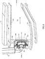
- FIG. 1 is a schematic diagram of an exemplary embodiment of a gas turbine engine 10.
- the gas turbine engine 10 is depicted as a turbofan that incorporates a fan section 20, a compressor section 30, a combustion section 40, and a turbine section 50.
- the combustion section 40 incorporates a combustor 100 that includes a plurality of fuel injectors 150 that are positioned annularly about a centerline 2 of the engine 10 upstream of the turbines 52, 54.
- the terms “forward” or “upstream” are used to refer to directions and positions located axially closer toward a fuel/air intake side of a combustion system than directions and positions referenced as “aft” or “downstream.”
- the fuel injectors 150 are inserted into and provide fuel to one or more combustion chambers for mixing and/or ignition. It is to be understood that the combustor 100 and fuel injector 150 as disclosed herein are not limited in application to the depicted embodiment of a gas turbine engine 10, but are applicable to other types of gas turbine engines, such as those used to power modern aircraft, to power sea vessels, to generate electrical power, and in industrial applications.
- FIG. 2 is a partial perspective view of an exemplary embodiment of a combustor 100 of a gas turbine engine 10.
- the combustor 100 is positioned between the compressor section 30 and the turbine section 50 of a gas turbine engine 10.
- the exemplary combustor 100 includes an annular combustion chamber 130 bounded by an inner (inboard) wall 132 and an outer (outboard) wall 134 and a forward bulkhead wall 136 spanning between the walls 132, 134 at the forward end of the combustor 100.
- the bulkhead wall 136 of the combustor 100 carries a plurality of mixer assemblies 200, including the fuel nozzle 152 of a fuel injector 150, a main mixer 220, and a pilot mixer 210.
- the combustor 100 may include a plurality of mixer assemblies 200 circumferentially distributed and mounted at the forward end of the combustor 100.
- a number of sparkplugs (not shown) are positioned with their working ends along a forward portion of the combustion chamber 130 to initiate combustion of the fuel and air mixture.
- the combusting mixture is driven downstream within the combustor 100 along a principal flowpath 170 toward the turbine section 50 of the engine 10.
- the fuel and air provided to the pilot mixer 210 produce a primary combustion zone 110 within a central portion of the combustion chamber 130.
- the fuel and air provided to the main mixer 220 produce a secondary combustion zone 120 in the combustion chamber 130 that is radially outwardly spaced from and concentrically surrounds the primary combustion zone 110.
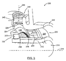
- FIG. 3 is an enlarged partial perspective view of an exemplary embodiment of the mixer assembly 200 for the exemplary combustor 100 of FIG. 2 .
- the exemplary mixer assembly 200 includes a main mixer 220 and a pilot mixer 210.
- the pilot mixer 210 and the main mixer 220 are concentrically arranged with the pilot mixer 210 located in the center of the main mixer 220, which surrounds a portion of the pilot mixer 210.
- the mixer assembly 200 has a centerline axis 218.
- the pilot mixer 210 includes an annular pilot mixer housing 212 separating and sheltering the pilot mixer 210 from the main mixer 220.
- the main mixer 220 further includes an annular main mixer outer radial wall 222 radially surrounding a portion of the annular pilot mixer housing 212, the outer surface of which forms an annular main mixer inner radial wall 219, and a main mixer forward wall 224 substantially perpendicular to and connecting the annular main mixer outer radial wall 222 and the annular main mixer inner radial wall 219, forming a main mixer annular cavity 228.
- the annular main mixer outer radial wall 222 further incorporates a first outer radial wall swirler 240, while the main mixer forward wall 224 further incorporates a first forward wall swirler 230 and a plurality of fuel injection holes 226 circumferentially distributed between the first outer radial wall swirler 240 and the first forward wall swirler 230 around the main mixer forward wall 224.
- the fuel injection holes 226 can be located proximate the first forward wall swirler 230 in the main mixer forward wall 224 as well.
- the fuel injection holes 226 are in flow communication with a fuel manifold (not shown), which in turn is in flow communication with a fuel supply.
- the exemplary embodiments of mixer assemblies 200 can also be used with gaseous fuel or partially vaporized fuel.
- the first outer radial wall swirler 240 is positioned on a first side of the fuel injection holes 226, while the first forward wall swirler 230 is positioned on a second side of the fuel injection holes 226.
- the first side is substantially opposite of the second side.
- the first outer radial wall swirler 240 is incorporated into the annular main mixer outer radial wall 222 and has an axis 248 oriented substantially radially to the centerline axis 218 of the mixer assembly 200.
- the first forward wall swirler 230 is incorporated into the main mixer forward wall 224 and is oriented substantially parallel or axially to the centerline axis 218 of the mixer assembly 200.
- the swirlers 230, 240 each have a plurality of vanes for swirling air traveling through the swirlers to mix the air and the fuel dispensed by the fuel injection holes 226.
- the first outer radial wall swirler 240 includes a first plurality of vanes 242 forming a first plurality of air passages 244 between the vanes 242.
- the vanes 242 are oriented at an angle with respect to axis 248 to cause the air to rotate in the main mixer annular cavity 228 in a first direction (e.g., clockwise).
- the first forward wall swirler 230 includes a second plurality of vanes 232 forming a second plurality of air passages 234 between the vanes 232.
- the vanes 232 are oriented at an angle with respect to the centerline axis 218 to cause the air to rotate in the main mixer annular cavity 228 in a second direction (e.g., counterclockwise).
- the air flowing through the first outer radial wall swirler 240 will be swirled in a first direction and the air flowing through the first forward wall swirler 230 will be swirled in a direction substantially opposite of the first direction.
- the air flowing through the first outer radial wall swirler 240 has an axis 248 oriented substantially radially to the centerline axis 218 of the mixer assembly 200, while the air flowing through the first forward wall swirler 230 has an axis oriented substantially axially to the centerline axis 218 of the mixer assembly 200.
- the fuel is injected through the fuel injection holes 226 between the radial first outer radial wall swirler 240 and the axial first forward wall swirler 230.
- the fuel is injected through the fuel injection holes 226 that are oriented substantially perpendicularly to axis 248 and the flow of air from the radial first outer radial wall swirler 240, which atomizes and disperses the fuel.
- the fuel then is atomized and dispersed again by the flow of air from the axial first forward wall swirler 230, thus atomizing the fuel by airflow from two sides.
- the fuel injection holes 226 can be located proximate the first forward wall swirler 230 in the main mixer forward wall 224 and be oriented substantially perpendicularly to the axis of the first forward wall swirler 230 and the flow of air from the radial first forward wall swirler 230, which atomizes and disperses the fuel. The fuel then is atomized and dispersed again by the flow of air from the axial first outer radial wall swirler 240, thus atomizing the fuel by airflow from two sides.
- annular main mixer cavity 228 In either configuration, an intense mixing region 229 of fuel and air is created within annular main mixer cavity 228 axially adjacent to the fuel injection holes 226, allowing the majority of fuel and air to be mixed before entering the downstream end of the annular main mixer cavity 228.
- This configuration reduces the dependence upon the ratio of the momentum of the fuel to the momentum of the air, increases the degree of atomization and mixing by injecting the fuel at a point of high turbulence, and reduces the potential for flame holding by reducing the potential for forming a wake region and lengthening the potential mixing distance.
- the configuration of the vanes in the swirlers may be altered to vary the swirl direction of air flowing and are not limited to the exemplary swirl directions indicated.
- the number of radial and axial swirlers can be modified (e.g., , the first outer radial wall swirler 240 can be replaced by a plurality of radial swirlers and the first forward wall swirler 230 can be replaced by a plurality of axial swirlers).
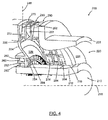
- FIG. 4 is an enlarged partial perspective view of another exemplary embodiment of the mixer assembly 200 for the exemplary combustor 100 of FIG. 2 .
- the exemplary mixer assembly 200 includes a main mixer 220 and a pilot mixer 210.
- the pilot mixer 210 includes an annular pilot mixer housing 212 separating and sheltering the pilot mixer 210 from the main mixer 220.
- the main mixer 220 further includes an annular main mixer outer radial wall 222 radially surrounding a portion of the annular pilot mixer housing 212, the outer surface of which forms an annular main mixer inner radial wall 219, and a main mixer forward wall 224 substantially perpendicular to and connecting the annular main mixer outer radial wall 222 and the annular main mixer inner radial wall 219, forming a main mixer annular cavity 228.
- the annular main mixer outer radial wall 222 further incorporates a plurality of outer radial wall swirlers, including a first outer radial wall swirler 270, a second outer radial wall swirler 280, and a third outer radial wall swirler 290, while the main mixer forward wall 224 further incorporates a plurality of forward wall swirlers, including a first forward wall swirler 250, a second forward wall swirler 260, and a plurality of fuel injection holes 226 circumferentially distributed between the second forward wall swirler 260 and the first outer radial wall swirler 270 around the main mixer forward wall 224.
- the fuel injection holes 226 can be located proximate the second forward wall swirler 260 in the main mixer forward wall 224 as well.
- the fuel injection holes 226 are in flow communication with a fuel manifold (not shown), which in turn is in flow communication with a fuel supply.
- a fuel manifold not shown
- the exemplary embodiments of mixer assemblies 200 can also be used with gaseous fuel or partially vaporized fuel. As can be seen in FIG.
- the first, second, and third outer radial wall swirlers 270, 280, 290 are positioned on a first side of the fuel injection holes 226, while the first and second forward wall swirlers 250, 260 are positioned on the second side of the fuel injection holes 226.
- the first side is substantially opposite of the second side.
- the first, second, and third outer radial wall swirlers 270, 280, 290 are incorporated into the annular main mixer outer radial wall 222 and each have an axis 248 oriented substantially radially to the centerline axis 218 of the mixer assembly 200.
- the first and second forward wall swirlers 250, 260 are incorporated into the main mixer forward wall 224 and are oriented substantially parallel or axially to the centerline axis 218 of the mixer assembly 200.
- Swirlers 250, 260, 270, 280, 290 each have a plurality of vanes for swirling air traveling through the swirlers to mix the air and the fuel dispensed by the fuel injection holes 226.
- the first outer radial wall swirler 270 includes a first plurality of vanes 272 forming a first plurality of air passages 274 between the vanes 272.
- the vanes 272 are oriented at an angle with respect to axis 248 to cause the air to rotate in the main mixer annular cavity 228 in a first direction (e.g., clockwise).
- the second outer radial wall swirler 280 includes a second plurality of vanes 282 forming a second plurality of air passages 284 between the vanes 282.
- the vanes 282 are oriented at an angle with respect to axis 248 to cause the air to rotate in the main mixer annular cavity 228 in a second direction (e.g., counterclockwise).
- the third outer radial wall swirler 290 includes a third plurality of vanes 292 forming a third plurality of air passages 294 between the vanes 292.
- the vanes 292 are oriented at an angle with respect to axis 248 to cause the air to rotate in the main mixer annular cavity 228 in a third direction.
- the third direction can be substantially the same as the first direction which are substantially opposite of the second direction.
- the first forward wall swirler 250 includes a fourth plurality of vanes 252 forming a fourth plurality of air passages 254 between the vanes 252.
- the vanes 252 are oriented at an angle with respect to the centerline axis 218 to cause the air to rotate in the main mixer annular cavity 228 in a fourth direction (e.g., counterclockwise).
- the second forward wall swirler 260 includes a fifth plurality of vanes 262 forming a fifth plurality of air passages 264 between the vanes 262.
- the vanes 262 are oriented at an angle with respect to the centerline axis 218 to cause the air to rotate in the main mixer annular cavity 228 in a fifth direction (e.g., clockwise).
- the fourth direction is substantially opposite of the fifth direction.
- the clockwise air passing through the first outer radial wall swirler 270 and the third outer radial wall swirler 290 counter-rates against the counterclockwise air passing through the second outer radial wall swirler 280, increasing the turbulence, which improves mixing.
- the counterclockwise air passing through the first forward wall swirler 250 counter-rates against the clockwise air passing through the second forward wall swirler 260, increasing the turbulence, which improves mixing.
- the air flowing through the first, second, and third outer radial wall swirlers 270, 280, 290 has an axis 248 oriented substantially radially to the centerline axis 218 of the mixer assembly 200, while the air flowing through the first and second forward wall swirlers 250, 260 has an axis oriented substantially axially to the centerline axis 218 of the mixer assembly 200.
- the fuel is injected through the fuel injection holes 226 between the radial first, second, and third outer radial wall swirlers 270, 280, 290 and the axial first and second forward wall swirlers 250, 260.
- the fuel is injected through the fuel injection holes 226 that are oriented substantially perpendicularly to axis 248 and the flow of air from the plurality of outer radial wall swirlers (first, second, and third outer radial wall swirlers 270, 280, 290), which atomizes and disperses the fuel.
- the fuel then is atomized and dispersed again by the flow of air from the plurality of forward wall swirlers (first and second forward wall swirlers 240, 250), thus atomizing the fuel by airflow from two sides.
- the fuel injection holes 226 can be located proximate the plurality of forward wall swirlers 250, 260 in the main mixer forward wall 224 and be oriented substantially perpendicularly to the axis and the flow of air from the plurality of forward wall swirlers 250, 260, which atomizes and disperses the fuel.
- the fuel then is atomized and dispersed again by the flow of air from the plurality of outer radial wall swirlers 270, 280, 290, thus atomizing the fuel by airflow from two sides.
- annular main mixer cavity 228 In either configuration, an intense mixing region 229 of fuel and air is created within annular main mixer cavity 228 axially adjacent to the fuel injection holes 226, allowing the majority of fuel and air to be mixed before entering the downstream end of the annular main mixer cavity 228.
- the number of axial swirlers, the number of radial swirlers, and the configuration of the vanes in the swirlers may be altered to vary the swirl direction of air flowing and are not limited to the exemplary swirl directions indicated.
Applications Claiming Priority (1)
| Application Number | Priority Date | Filing Date | Title |
|---|---|---|---|
| US14/593,877 US9920932B2 (en) | 2011-01-26 | 2015-01-09 | Mixer assembly for a gas turbine engine |
Publications (1)
| Publication Number | Publication Date |
|---|---|
| EP3043116A1 true EP3043116A1 (fr) | 2016-07-13 |
Family
ID=55077467
Family Applications (1)
| Application Number | Title | Priority Date | Filing Date |
|---|---|---|---|
| EP16150812.2A Withdrawn EP3043116A1 (fr) | 2015-01-09 | 2016-01-11 | Ensemble formant mélangeur pour moteur à turbine à gaz |
Country Status (1)
| Country | Link |
|---|---|
| EP (1) | EP3043116A1 (fr) |
Cited By (1)
| Publication number | Priority date | Publication date | Assignee | Title |
|---|---|---|---|---|
| US20190170356A1 (en) * | 2016-05-31 | 2019-06-06 | Nuovo Pignone Tecnologie Srl | Fuel nozzle for a gas turbine with radial swirler and axial swirler and gas turbine |
Citations (1)
| Publication number | Priority date | Publication date | Assignee | Title |
|---|---|---|---|---|
| EP2481982A1 (fr) * | 2011-01-26 | 2012-08-01 | United Technologies Corporation | Assemblage de mélangeur pour moteur de turbine à gaz |
-
2016
- 2016-01-11 EP EP16150812.2A patent/EP3043116A1/fr not_active Withdrawn
Patent Citations (1)
| Publication number | Priority date | Publication date | Assignee | Title |
|---|---|---|---|---|
| EP2481982A1 (fr) * | 2011-01-26 | 2012-08-01 | United Technologies Corporation | Assemblage de mélangeur pour moteur de turbine à gaz |
Cited By (2)
| Publication number | Priority date | Publication date | Assignee | Title |
|---|---|---|---|---|
| US20190170356A1 (en) * | 2016-05-31 | 2019-06-06 | Nuovo Pignone Tecnologie Srl | Fuel nozzle for a gas turbine with radial swirler and axial swirler and gas turbine |
| US11649965B2 (en) * | 2016-05-31 | 2023-05-16 | Nuovo Pignone Tecnologie Srl | Fuel nozzle for a gas turbine with radial swirler and axial swirler and gas turbine |
Similar Documents
| Publication | Publication Date | Title |
|---|---|---|
| EP2481982B1 (fr) | Assemblage de mélangeur pour moteur de turbine à gaz | |
| US10718524B2 (en) | Mixer assembly for a gas turbine engine | |
| EP2481987B1 (fr) | Assemblage de mélangeur pour moteur de turbine à gaz | |
| US6381964B1 (en) | Multiple annular combustion chamber swirler having atomizing pilot | |
| US6363726B1 (en) | Mixer having multiple swirlers | |
| EP2479498B1 (fr) | Chambre de combustion de turbine à gaz et procédé de fonctionnement | |
| US9074773B2 (en) | Combustor assembly with trapped vortex cavity | |
| JP4658471B2 (ja) | ガスタービンエンジンの燃焼器エミッションを減少させる方法及び装置 | |
| US7685823B2 (en) | Airflow distribution to a low emissions combustor | |
| US10480791B2 (en) | Fuel injector to facilitate reduced NOx emissions in a combustor system | |
| US20020162333A1 (en) | Partial premix dual circuit fuel injector | |
| US20090320484A1 (en) | Methods and systems to facilitate reducing flashback/flame holding in combustion systems | |
| US20090113893A1 (en) | Pilot mixer for mixer assembly of a gas turbine engine combustor having a primary fuel injector and a plurality of secondary fuel injection ports | |
| EP2241816A2 (fr) | Injecteur de carburant pilote à double orifice | |
| US20150159877A1 (en) | Late lean injection manifold mixing system | |
| EP2481985B1 (fr) | Ensemble d'injecteur de carburant | |
| US6729141B2 (en) | Microturbine with auxiliary air tubes for NOx emission reduction | |
| EP3425281B1 (fr) | Buse pilote dotée de prémélange en ligne | |
| US11906165B2 (en) | Gas turbine nozzle having an inner air swirler passage and plural exterior fuel passages | |
| EP3043116A1 (fr) | Ensemble formant mélangeur pour moteur à turbine à gaz | |
| Dai et al. | Mixer Assembly for a Gas Turbine Engine | |
| EP4202302A1 (fr) | Buse de combustible et tourbillonneur | |
| US20230220802A1 (en) | Combustor with lean openings | |
| CA2596789A1 (fr) | Melangeur pilote pour melangeur d'une chambre de combustion de turbine a gaz, equipee d'un injecteur de carburant primaire et de multiples ports d'injection secondaire de carburant |
Legal Events
| Date | Code | Title | Description |
|---|---|---|---|
| PUAI | Public reference made under article 153(3) epc to a published international application that has entered the european phase |
Free format text: ORIGINAL CODE: 0009012 |
|
| AK | Designated contracting states |
Kind code of ref document: A1 Designated state(s): AL AT BE BG CH CY CZ DE DK EE ES FI FR GB GR HR HU IE IS IT LI LT LU LV MC MK MT NL NO PL PT RO RS SE SI SK SM TR |
|
| AX | Request for extension of the european patent |
Extension state: BA ME |
|
| RAP1 | Party data changed (applicant data changed or rights of an application transferred) |
Owner name: UNITED TECHNOLOGIES CORPORATION |
|
| STAA | Information on the status of an ep patent application or granted ep patent |
Free format text: STATUS: THE APPLICATION IS DEEMED TO BE WITHDRAWN |
|
| 18D | Application deemed to be withdrawn |
Effective date: 20170114 |