EP3042774A1 - Connection member and inkjet recording device equipped with same connection member - Google Patents
Connection member and inkjet recording device equipped with same connection member Download PDFInfo
- Publication number
- EP3042774A1 EP3042774A1 EP14851943.2A EP14851943A EP3042774A1 EP 3042774 A1 EP3042774 A1 EP 3042774A1 EP 14851943 A EP14851943 A EP 14851943A EP 3042774 A1 EP3042774 A1 EP 3042774A1
- Authority
- EP
- European Patent Office
- Prior art keywords
- connection member
- component
- communicating portion
- communicating
- aperture
- Prior art date
- Legal status (The legal status is an assumption and is not a legal conclusion. Google has not performed a legal analysis and makes no representation as to the accuracy of the status listed.)
- Granted
Links
Images



Classifications
-
- B—PERFORMING OPERATIONS; TRANSPORTING
- B41—PRINTING; LINING MACHINES; TYPEWRITERS; STAMPS
- B41J—TYPEWRITERS; SELECTIVE PRINTING MECHANISMS, i.e. MECHANISMS PRINTING OTHERWISE THAN FROM A FORME; CORRECTION OF TYPOGRAPHICAL ERRORS
- B41J2/00—Typewriters or selective printing mechanisms characterised by the printing or marking process for which they are designed
- B41J2/005—Typewriters or selective printing mechanisms characterised by the printing or marking process for which they are designed characterised by bringing liquid or particles selectively into contact with a printing material
- B41J2/01—Ink jet
- B41J2/17—Ink jet characterised by ink handling
- B41J2/175—Ink supply systems ; Circuit parts therefor
- B41J2/17503—Ink cartridges
- B41J2/1752—Mounting within the printer
-
- B—PERFORMING OPERATIONS; TRANSPORTING
- B41—PRINTING; LINING MACHINES; TYPEWRITERS; STAMPS
- B41J—TYPEWRITERS; SELECTIVE PRINTING MECHANISMS, i.e. MECHANISMS PRINTING OTHERWISE THAN FROM A FORME; CORRECTION OF TYPOGRAPHICAL ERRORS
- B41J2/00—Typewriters or selective printing mechanisms characterised by the printing or marking process for which they are designed
- B41J2/005—Typewriters or selective printing mechanisms characterised by the printing or marking process for which they are designed characterised by bringing liquid or particles selectively into contact with a printing material
- B41J2/01—Ink jet
-
- B—PERFORMING OPERATIONS; TRANSPORTING
- B41—PRINTING; LINING MACHINES; TYPEWRITERS; STAMPS
- B41J—TYPEWRITERS; SELECTIVE PRINTING MECHANISMS, i.e. MECHANISMS PRINTING OTHERWISE THAN FROM A FORME; CORRECTION OF TYPOGRAPHICAL ERRORS
- B41J2/00—Typewriters or selective printing mechanisms characterised by the printing or marking process for which they are designed
- B41J2/005—Typewriters or selective printing mechanisms characterised by the printing or marking process for which they are designed characterised by bringing liquid or particles selectively into contact with a printing material
- B41J2/01—Ink jet
- B41J2/17—Ink jet characterised by ink handling
- B41J2/175—Ink supply systems ; Circuit parts therefor
- B41J2/17503—Ink cartridges
- B41J2/1752—Mounting within the printer
- B41J2/17523—Ink connection
-
- B—PERFORMING OPERATIONS; TRANSPORTING
- B41—PRINTING; LINING MACHINES; TYPEWRITERS; STAMPS
- B41J—TYPEWRITERS; SELECTIVE PRINTING MECHANISMS, i.e. MECHANISMS PRINTING OTHERWISE THAN FROM A FORME; CORRECTION OF TYPOGRAPHICAL ERRORS
- B41J2/00—Typewriters or selective printing mechanisms characterised by the printing or marking process for which they are designed
- B41J2/005—Typewriters or selective printing mechanisms characterised by the printing or marking process for which they are designed characterised by bringing liquid or particles selectively into contact with a printing material
- B41J2/01—Ink jet
- B41J2/135—Nozzles
- B41J2/14—Structure thereof only for on-demand ink jet heads
- B41J2002/14491—Electrical connection
Definitions
- the present invention relates to a connection member for use in connecting two different components in a manner that the components can communicate with each other, and an inkjet recording device equipped with the connection member.
- connection members may be used as means for connecting two different components to establish communication between the components.
- inkjet recording devices use ink feed tubes as a connection member that connects recording heads and an ink storage tank to allow them to communicate with each other.
- the ink feed tubes are connected to the recording heads, and the ink storage tank is connected to the ink feed tubes.
- the ink in the storage tank runs through the ink feed tubes into the recording heads.
- Patent Document 1 discloses an ink feeding structure wherein a storage tank and recording heads are connected with such ink feed tubes.
- the ink feeding structure disclosed in this document uses first and second joint members to connect the storage tank and the recording heads.
- the first joint members are connected to ink guiding tubes connected to the recording heads, and the second joint members are connected to ink guiding tubes connected to the storage tank. Then, the first and second joint members are connected to allow the recording heads and the storage tank to communicate with each other.
- Patent Document 1 JP 2004-268599 A (disclosed on September 30, 2004)
- Patent Document 1 The ink feeding structure described in Patent Document 1 is effectuated by inserting the first joint member in the second joint member.
- Such a structure that uses an external member and an internal member for connection requires the fabrication of these two different members. This doubles the die cost, consequently increasing an overall production cost. Additionally, the external member and the internal member need to be discerned and then attached to two components to be connected. This is rather a laborsome procedure.
- connection member that can be fabricated at low cost and easily attached to a target component, and an inkjet recording device equipped with the connection member.
- a connection member is a connection member to be connected to and to communicate with a first component, the connection member being further connectable to another connection member to be connected to and to communicate with a second component, the connection member including: a communicating portion connectable to and communicatable with the first component; an engaging portion engageable into the other connection member; and an engaged portion into which the other connection member is engageable, wherein the connection member and the other connection member are mutually connectable to communicate with each other.
- connection member by engaging the connection member and the other connection member with each other, the first component connected to and communicating with the communicating portion of the connection member and the second component connected to and communicating with another communicating portion of the other connection member may be mutually connected to communicate with each other.
- the connection member according to this aspect engages into the other connection member, while receiving the other connection member engaged therein.
- the connection member has two portions; an engaging portion that engages into the other connection member, and an engaged portion into which the other connection member is engaged. Since the two connection members according to this aspect are thus engageable with each other, the external and internal members can be dispensed with. When these connection members are attached to two components to be connected, therefore, discerning external and internal members, as in the conventional art, is unnecessary, markedly facilitating the workload. It is particularly advantageous to use two connection members of one type that requires only one die to fabricate them. This may reduce the die cost as compared to the conventional example that requires the fabrication of external and internal members, consequently curtailing an overall production cost.
- the engaging portion may be located at a position closer to the communicating portion than the engaged portion, and the engaging portion and the engaged portion may be spaced at an interval.
- an interval between the engaging portion and the engaged portion may serve to increase a degree of engagement between the connection member and the other connection member.
- a larger engaging intensity engaging force
- the communicating portion of the connection member may have a tubular shape, and the communicating portion may have a part having a largest aperture whose side surface is parallel to a lengthwise direction thereof.
- the part having a largest aperture at the connecting end of the communicating portion has a side surface parallel to the lengthwise direction. Then, fully intimate contact may be achieved between the part having a largest aperture and the inner surface of the component's connecting port. This may improve sealing properties between the communicating portion and the connecting port of the component, making the connection member and the component inseparable. Because of the improved sealing properties between the communicating portion and the connecting port of the component, any displacement of the connecting port of the component is unlikely to result in a gap between the communicating portion and the connecting port. This may avoid possible leakage of fluid (for example, ink) through such a gap.
- fluid for example, ink
- the communicating portion may have a part having a smallest aperture whose side surface is parallel to the lengthwise direction at a lower end thereof than the part having a largest aperture, and the communicating portion may further have, at a position opposite to the part having a smallest aperture across the part having a largest aperture, a part larger in aperture than the part having a smallest aperture and smaller in aperture than the part having a largest aperture (i.e., a part having a mid-sized aperture), wherein the part having a mid-sized aperture has a side surface parallel to the lengthwise direction.
- the part having a smallest aperture and the part having a mid-sized aperture at the connecting end of the communicating portion respectively have side surfaces parallel to the lengthwise direction. Then, fully intimate contact may be further ensured between the inner surface of the component's connecting port and the part having a largest aperture, the part having a smallest aperture, and the part having a mid-sized aperture. This may further improve sealing properties between the communicating portion and the connecting port of the component, making the connection member and the component more inseparable.
- a stepwise part is formed between the part having a largest aperture and the part having a mid-sized aperture.
- Such a stepwise part may make the communicating portion and the connecting port of the component even more inseparable.
- an inkjet recording device includes any one of the connection members so far described.
- connection members thus advantageous and fabricated at low cost, a plurality of components in the inkjet recording device may be easily connected.
- the components may be engageable with each other using two connection members, making external and internal members unnecessary.
- connection members When these connection members are attached to two components to be connected, therefore, discerning external and internal members, as in the conventional art, is unnecessary, markedly facilitating the workload.
- connection members of one type that requires only one die to fabricate them. This may reduce the die cost as compared to the conventional example that requires the fabrication of external and internal members, consequently curtailing an overall production cost.
- connection member according to the invention may be for use in connecting two components.
- the connection member may be unlimitedly applicable to various fields and any parts of devices in which the connection member is utilizable.
- the connection member according to the invention is hereinafter described by way of embodiments wherein the connection member is applied to an inkjet recording device.
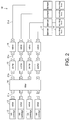
- FIG. 2 is a block diagram of an ink supply unit 10 in the inkjet recording device according to this embodiment.
- the ink supply unit 10 is structured to allow inks to circulate between ink cartridges 12 and recording heads 18.
- the ink cartridges 12 each have an openable and closable valve 13.
- a filter 14 for removal of foreign matter from the ink a pump 15 as a driving source that circulates the ink passing through the filter 14 to the recording head 18, and an openable and closable valve 16.
- a damper 17 that regulates the supply pressure of the ink to be supplied to the recording head 18, and the recording head 18.
- the damper 17 When the pressure in the damper 17 is lowered in response to the ink discharge through the discharge nozzle (not illustrated in the drawings) of the recording head 18, the damper 17 opens the valve 13 and the valve 16 to circulate the ink from the ink cartridge 12 to the recording head 18 for refill.
- the ink supply unit 10 includes different components that are connected to one another.
- the connection member according to this embodiment may be used to connect a first pipe 21a and a valve 13 in this structure.
- the connection member according to this embodiment may also be used to connect a first pipe 21a and a filter 14 in this structure.
- the connection member according to this embodiment may also be used to connect other components, for example, second pipe 21b and filter 14, second pipe 21b and pump 15, third pipe 21c and pump 15, third pipe 21c and valve 16, or fourth pipe 21d and valve 16.
- a simpler term, "component” may hereinafter refer to these parts of the device.
- connection member [Structural features of connection member]
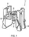
- FIG. 1 is a perspective view of the connection member according to this embodiment.
- the connection member 1 has a communicating portion 2, a mating portion 3, engaging portions 4, engaged portions 5, and holding portions 6.
- the communicating portion 2 has a tubular shape and is connected to and communicating with one of the components described above (for example, valve 13) at one end thereof (lower end in the drawing).
- the communicating portion 2 by being inserted in a connecting port of the component, is connected to and communicating with the component.
- the mating portion 3 is communicatably formed at the other end (upper end in the drawing) of the communicating portion 2.
- the mating portion 3 has the engaging portions 4 and the engaged portions 5.
- the holding portions 6 are formed at end parts of the engaged portions 5 closer to the component.
- the drawing shows two engaging portions 4 formed at opposite positions on the side surface of the mating portion 3.
- the drawing also shows two engaged portions 5 formed at opposite positions across the two engaging portions 4.
- the numbers of these portions are given as non-limiting examples.
- the connection member 1 may have an optional number of engaging portions 4 and/or engaged portions 5.
- connection member refers to a connection member to be connected to and to communicate with the component.
- the other connection member may have a communicating portion.
- the communicating portion is connectable and communicatable with the component at one end thereof and has a mating portion at the other end thereof.
- another (the other) communicating portion may refer to the communicating portion of another (the other) connection member
- another (the other) mating portion may refer to the mating portion of another (the other) connection member in the description hereinafter given.
- the mating portion 3 is communicatably mated with the other mating portion of the other connection member.
- the other mating portion is formed so as to communicate with the other communicating portion.
- the connection member 1 according to this embodiment engages into the other connection member, while receiving the other connection member engaged therein.
- the engaging portion 4 has a shape allowed to engage into the other connection member (for example, protrusion or claw).
- the engaged portion 5 has a shape allowed to receive the other connection member engaged therein (for example, opening or groove).
- FIG. 1 shows the engaging portion 4 in the form of a claw and the engaged portion 5 in the form of an opening.
- the mating portion 3 has such a shape that allows this mating portion and the other mating portion of the other connection member to be capable of mating with each other (for example, a shape complementary to the shape of the other mating portion).
- an end part of the communicating portion 2 at which the mating portion 3 is formed is coincident in shape with an end part of the other communicating portion at which the other mating portion is formed.
- the holding portions 6 are for gripping the connection member 1 when the connection member 1 is engaged with the other connection member.
- the two engaged portions 5 may be deflected outward on both sides of the connection member 1 away from each other. This deflection of the engaged portions 5 may be usefully leveraged to engage the connection member 1 and the other connection member. As a result, these connection members may be mutually engageable with ease.
- the holding portions 6 may facilitate disengagement, as well as the engagement, between the connection member 1 and the other connection member.
- the component connected to and communicating with the communicating portion 2 of the connection member 1 may be replaced or regularly inspected.
- the component could be removable directly from the communicating portion 2 of the connection member 1. This is, however, impractical due to possible difficulty in removing the component or the risk of loosening the connection between the communicating portion 2 and the component after repeated removals.
- removing the connection member 1 and the component altogether by gripping the holding portions 6 may facilitate the removal work and hardly affect the connection between the communicating portion 2 and the component.
- a non-slip material may be attached to the holding portion 6 as illustrated in FIG. 1 . Attaching the non-slip material to the holding portions 6 may make it easier to grip the holding portions 6 and help to readily know the location of the holding portions 6 in the connection member 1.
- the raw material of the connection member 1 may preferably be a substance resistant to solvent attack, such as polypropylene (PP) or polybutylene terephthalate (PBT), when a solvent ink is the fluid running through the communicating portion 2 of the connection member 1.
- PP polypropylene
- PBT polybutylene terephthalate
- the PP that makes the connection member 1 easier to deflect may be the most suitable material.
- the PP-based connection member 1, if colored in black, may be usable when an ultraviolet-curable ink is the fluid running inside.
- Polyoxymethylene (POM) may be usable at sections of the connection member 1 with no contact with the solvent ink.
- connection member [An exemplified engagement setup of connection member]
- connection member 1 may be engageable with another connection member 1.
- FIG. 3 illustrate the engagement of two connection members 1.
- FIGs. 3A to 3C are respectively an exploded view, a perspective view, and a sectional view of two connection members 1 being engaged with each other.
- connection members 1 and the other one of the connection members 1, being oriented oppositely, are engaged each other. Specifically, these members are engaged in a manner that the engaging portions 4 in one of the connection members 1 are oriented opposed to the engaged portions 5 in the other one of the connection members 1.
- FIG. 3B the engaging portions 4 in one of the connection members 1 engage into the engaged portions 5 in the other one of the connection members 1, while the engaging portions 4 in the other one of the connection members 1 engage into the engaged portions 5 in one of the connection member 1.
- the mating portion 3 in one of the connection members 1 and the mating portion 3 in the other one of the connection members 1 are mated with each other as illustrated in FIG. 3C .
- a rubber material 7 is inserted in between the two mating portions 3 to prevent possible leakage through any gap possibly generated between the communicating portions 2 where the mating portions 3 are formed.
- connection members 1 are engaged with each other.
- the component (first component) connected to and communicating with the communicating portion 2 in one of the connection members 1 and the component (second component) connected to and communicating with the communicating portion 2 in the other one of the connection members 1 are mutually connectable to communicate with each other.
- one of the connection members 1 engages into the other connection member 1, while receiving the other connection member 1 engaged therein.
- one connection member 1 has the engaging portions 4 that engage into the other connection member 1, and the engaged portions 5 into which the other connection member 1 is engaged.
- the components may be engageable with each other using two connection members 1, making external and internal members unnecessary.
- connection members When these connection members are attached to two components to be connected, therefore, discerning external and internal members, as in the conventional art, is unnecessary, markedly facilitating the workload. It is particularly advantageous to use two connection members 1 of one type that requires only one die to fabricate them. This may reduce the die cost as compared to the conventional example that requires the fabrication of external and internal members, consequently curtailing an overall production cost.
- connection member [Another exemplified engagement setup of connection member]
- connection member 1 may be engageable with connection members of different types. Examples of such connection members are described below.
- FIGs. 4A and 4B are perspective views of connection members structured differently to the connection member 1.
- connection member 1 may be engaged with a connection member 1a illustrated in FIG. 4A .
- the connection member 1a has a communicating portion 2, a mating portion 3, engaging portions 4, engaged portions 5, and holding portions 6.
- the communicating portion 2 of this connection member unlike the connection member 1, is bent at its midpoint.
- the component connected to and communicating with the communicating portion 2 of the connection member 1 and the component connected to and communicating with the communicating portion 2 of the connection member 1a are mutually connectable to communicate with each other.
- the communicating portions 2 of the two connection members 1 are coaxial.
- the connection member 1a described in this example has the communicating portion 2 bent at its midpoint, and thus the communicating portions 2 of the connection member 1 and the connection member 1a are oriented differently.
- Such connection members as the connection member 1a having the communicating portion 2 bent at its midpoint may be useful when the direction of communication between two components is desirably changed. It should be understood that the communicating portion 2 of the connection member 1a may be bendable through an optional angle.
- connection member 1 may be engaged with a connection member 1b illustrated in FIG. 4B .
- the connection member 1b has two communicating portions 2a and 2b, a mating portion 3, engaging portions 4, and holding portions 6.
- This connection member differs from the connection member 1 in having two engaging portions 2a and 2b but no engaged portion 5.
- the engaging portions 4 of the connection member 1b engage into the engaged portions 5 of the connection member 1, but not the other way around.
- the mating portions 3 of the connection member 1 and the connection member 1b are mated with each other.
- connection member 1b may allow three components to be connected and communicate with one another.
- the connection member 1b may be useful when changing a flow rate or diverging a flow into sub flows is desirable. It should be understood that the connection member 1b may have three or more communicating portions.
- connection member 1a was described as an example of differently structured connection members. Instead, the connection member 1a may be used in place of the connection member 1.
- This embodiment includes in its scope the engagement between two connection members 1a and the engagement between connection members 1a and 1b. It should be understood that the connection member 1 may have a plurality of communicating portions like the connection member 1b.
- connection member [An exemplified use of connection member]
- connection member 1 may be usable to connect the first pipe 21a and the filter 14 of the ink supply unit 10 illustrated in FIG. 2 .
- first pipe 21a is communicatably connected to the communicating portion 2 of the connection member 1
- the filter 14 is communicatably connected to another communicating portion of another connection member (for example, another connection member 1).
- the engaging portions 4 of the connection member 1 engage into the other connection member, while the other connection member engages into the engaged portions 5 of the connection member 1.
- the mating portion 3 is communicatably mated with another mating portion of the other connection member.
- the first pipe 21 a connected to and communicating with the communicating portion 2 of the connection member 1 and the filter 14 connected to and communicating with another communicating portion of the other connection member are mutually connectable to communicate with each other.
- the filter 14 is connected to another communicating portion of another connection member, but the invention is not limited to this.
- the connecting port of the filter 14 may be formed in the same shape as another connection member. This may allow the connecting port of the filter 14 to be directly usable as another connection member.
- FIG. 5 is a drawing that illustrates the use of the connecting port of the filter 14 as another connection member.
- engaging portions 4a and mating portions are formed at the connecting ports of the filters 14.
- the engaging portions 4a formed at the connecting port of the filter 14 engage into the engaged portions 5 of the connection member 1.
- the mating portion 3 of the connection member 1 and the mating portion formed at the connecting port of the filter 14 are mated with each other.
- the filter 14 and the first pipe 21a (not illustrated in the drawing) connected to and communicating with the communicating portion 2 of the connection member 1 are mutually connectable to communicate with each other.
- connection member 1 With the connecting port of the filter 14 serving as another connection member, the connection member 1 according to this embodiment may be directly engageable with the filter 14. In this instance, it only takes one connection member 1 to connect the filter 14 and the first pipe 21a to communicate with each other. This may reduce a required number of connection members, leading to cost reduction.
- connection ports of the pump 15 and the valves 13 and 16 may be usable as another connection member.
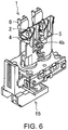
- FIG. 6 is a drawing of the connecting port of the pump 15 used as another connection member.
- FIG. 7 is a drawing of the connecting port of the valve 13 used as another connection member.
- engaging portions 4b and a mating portion are formed at the connecting port of the pump 15.
- the engaging portions 4b formed at the connecting port of the pump 15 engage into the engaged portions 5 of the connection member 1.
- the mating portion 3 of the connection member 1 and the mating portion formed at the connecting port of the filter 14 are mated with each other.
- the pump 15 and the component, such as the second pipe 21b (not illustrated in the drawing) connected to and communicating with the communicating portion 2 of the connection member 1 are mutually connectable to communicate with each other.
- engaging portions 4c and a mating portion are formed at the connecting port of the valve 13.
- the engaging portions 4c formed at the connecting port of the valve 13 engage into the engaged portions 5 of the connection member 1.
- the mating portion 3 of the connection member 1 and the mating portion formed at the connecting port of the valve 13 are mated with each other.
- the valve 13 and the component, such as the first pipe 21a (not illustrated in the drawing) connected to and communicating with the communicating portion 2 of the connection member 1 are mutually connectable to communicate with each other.
- connection member 1 may be usable to connect, in addition to the components so far exemplified, other components.
- the connection member 1 may be usable to connect pipes.
- the connection member 1 may be usable to connect pipes.
- connection member 1 may preferably have an interval between the engaging portions 4 and the engaged portions 5. This interval is a space for the rubber material 7 to be fitted in against another connection member.
- the engaging portions 4 are located at positions closer to the communicating portion 2 than the engaged portions 5. There is no contact between the engaging portions 4 and the engaged portions 5. Such an interval between the engaging portions 4 and the engaged portions 5 may provide for the advantage described below.
- the interval between the engaging portions 4 and the engaged portions 5 may serve to increase a degree of engagement between the connection member 1 and another connection member. As a result, a larger engaging intensity (engaging force) may be attainable, making the connection member and the other connection member inseparable.
- the engaged portions 5 may be more deflectable when the holding portions 6 are gripped. A larger deflection of the engaged portions 5 may facilitate the engagement between the connection member 1 and another connection member.
- FIG. 8 is an enlarged view of the connecting end of the communicating portion 2 to be connected to the component.
- the communicating portion 2 preferably has, at its connecting end to be connected to the component, a part 8b having a largest aperture whose side surface is parallel to the lengthwise direction.
- the part 8b having a largest aperture whose side surface is parallel to the lengthwise direction is formed at the connecting end of the communicating portion 2, fully intimate contact may be achieved between this part 8b of the communicating portion 2 and the inner surface of the component's connecting port. This may improve sealing properties between the communicating portion 2 and the connecting port of the component, making the connection member and the component inseparable.
- any displacement of the connecting port of the component is unlikely to result in a gap between the communicating portion 2 and the connecting port. This may avoid possible leakage of fluid (for example, ink) through such a gap.
- fluid for example, ink
- the communicating portion 2 may have a part 8a having a smallest aperture whose side surface is parallel to the lengthwise direction at a lower end thereof than the part 8b having a largest aperture, and the communicating portion 2 may further have, at a position opposite to the part 8a having a smallest aperture across the part 8b having a largest aperture, a part 8c larger in aperture than the part 8a having a smallest aperture and smaller in aperture than the part 8b having a largest aperture (i.e., a part having a mid-sized aperture), wherein the part 8c has a side surface parallel to the lengthwise direction.
- a stepwise part is formed between the part 8b having a largest aperture and the part 8c having a mid-sized aperture.
- Such a stepwise part may make the communicating portion 2 and the connecting port of the component even more inseparable.
- connection member 1 is a connection member 1 to be connected to and to communicate with a first component, the connection member 1 being further connectable to another connection member to be connected to and to communicate with a second component, the connection member 1 including: a communicating portion 2 connectable to and communicatable with the first component; engaging portions 4 engageable into the other connection member; and engaged portions 5 into which the other connection member is engageable, wherein the connection member 1 and the other connection member are mutually connectable to communicate with each other.
- connection member 1 By engaging the connection member 1 and the other connection member thus structured with each other, the first component connected to and communicating with the communicating portion 2 of the connection member 1 and the second component connected to and communicating with another communicating portion of the other connection member are mutually connectable to communicate with each other.
- the connection member 1 according to this embodiment engages into the other connection member, while receiving the other connection member engaged therein.
- the connection member 1 according to an aspect of the invention has the engaging portions 4 that engage into the other connection member, and the engaged portions 5 into which the other connection member is engaged.
- the components may be engageable with each other using two connection members 1 according to this embodiment, making external and internal members unnecessary.
- connection members When these connection members are attached to two components to be connected, therefore, discerning external and internal members, as in the conventional art, is unnecessary, markedly facilitating the workload. It is particularly advantageous to use two connection members 1 of one type that requires only one die to fabricate them. This may reduce the die cost as compared to the conventional example that requires the fabrication of external and internal members, consequently curtailing an overall production cost.
- the engaging portions 4 may be located at positions closer to the communicating portion 2 than the engaged portions 5, and the engaging portions 4 and the engaged portions 5 may be spaced at an interval.
- connection member 1 thus structured, an interval between the engaging portions 4 and the engaged portions 5 may serve to increase a degree of engagement between the connection member 1 and the other connection member. As a result, a larger engaging intensity (engaging force) may be attainable, making the connection member and another connection member inseparable.
- the communicating portion 2 of the connection member 1 may have a tubular shape, and the communicating portion 2 may have the part 8b having a largest aperture whose side surface is parallel to the lengthwise direction.
- the part 8b having a largest aperture at the connecting end of the communicating portion 2 has a side surface parallel to the lengthwise direction. Then, fully intimate contact may be achieved between the part 8b having a largest aperture and the inner surface of the component's connecting port. This may improve sealing properties between the communicating portion 2 and the connecting port of the component, making the communicating part and the connecting part inseparable. Because of the improved sealing properties between the communicating portion 2 and the connecting port of the component, any displacement of the connecting port of the component is unlikely to result in a gap between the communicating portion 2 and the connecting port. This may avoid possible leakage of fluid (for example, ink) through such a gap.
- fluid for example, ink
- the communicating portion 2 may have the part 8a having a smallest aperture whose side surface is parallel to the lengthwise direction at a lower end thereof than the part 8b having a largest aperture, and the communicating portion 2 may further have, at a position opposite to the part 8a having a smallest aperture across the part 8b having a largest aperture, the part 8c larger in aperture than the part 8a having a smallest aperture and smaller in aperture than the part 8b having a largest aperture (i.e., a part having a mid-sized aperture), wherein the part 8c has a side surface parallel to the lengthwise direction.
- connection member 1 the part 8a having a smallest aperture and the part 8c having a mid-sized aperture of the communicating portion 2 at its connecting end respectively have side surfaces parallel to the lengthwise direction. Then, fully intimate contact may be further ensured between the inner surface of the component's connecting port and the part 8a having a smallest aperture, the part 8b having a largest aperture, and the part 8c having a mid-sized aperture. This may further improve sealing properties between the communicating portion 2 and the connecting port of the component, making the connection member and the component more inseparable.
- the stepwise part is formed between the part 8b having a largest aperture and the part 8c having a mid-sized aperture.
- Such a stepwise part may make the communicating portion 2 and the connecting port of the component even more inseparable.
- An inkjet recording device includes any one of the connection members so far described.
- connection members 1 By using any one of the connection members 1 thus structured advantageous and fabricated at low cost, a plurality of components in the inkjet recording device may be easily connected to each other.
- connection member according to the present invention is suitable for use in connecting two components to establish communication therebetween, for example, valves, filters, pumps, and pipes of an inkjet recording device.
Landscapes
- Quick-Acting Or Multi-Walled Pipe Joints (AREA)
- Ink Jet (AREA)
Abstract
Description
- The present invention relates to a connection member for use in connecting two different components in a manner that the components can communicate with each other, and an inkjet recording device equipped with the connection member.
- Conventionally, connection members may be used as means for connecting two different components to establish communication between the components. For instance, some inkjet recording devices use ink feed tubes as a connection member that connects recording heads and an ink storage tank to allow them to communicate with each other. The ink feed tubes are connected to the recording heads, and the ink storage tank is connected to the ink feed tubes. The ink in the storage tank runs through the ink feed tubes into the recording heads.
-
Patent Document 1 discloses an ink feeding structure wherein a storage tank and recording heads are connected with such ink feed tubes. The ink feeding structure disclosed in this document uses first and second joint members to connect the storage tank and the recording heads. The first joint members are connected to ink guiding tubes connected to the recording heads, and the second joint members are connected to ink guiding tubes connected to the storage tank. Then, the first and second joint members are connected to allow the recording heads and the storage tank to communicate with each other. - Patent Document 1:
JP 2004-268599 A - The ink feeding structure described in
Patent Document 1 is effectuated by inserting the first joint member in the second joint member. Such a structure that uses an external member and an internal member for connection requires the fabrication of these two different members. This doubles the die cost, consequently increasing an overall production cost. Additionally, the external member and the internal member need to be discerned and then attached to two components to be connected. This is rather a laborsome procedure. - To address these conventional issues, the present invention provides a connection member that can be fabricated at low cost and easily attached to a target component, and an inkjet recording device equipped with the connection member.
- A connection member according to an aspect of the present invention is a connection member to be connected to and to communicate with a first component, the connection member being further connectable to another connection member to be connected to and to communicate with a second component, the connection member including: a communicating portion connectable to and communicatable with the first component; an engaging portion engageable into the other connection member; and an engaged portion into which the other connection member is engageable, wherein the connection member and the other connection member are mutually connectable to communicate with each other.
- According to this aspect, by engaging the connection member and the other connection member with each other, the first component connected to and communicating with the communicating portion of the connection member and the second component connected to and communicating with another communicating portion of the other connection member may be mutually connected to communicate with each other. The connection member according to this aspect engages into the other connection member, while receiving the other connection member engaged therein. In other words, the connection member has two portions; an engaging portion that engages into the other connection member, and an engaged portion into which the other connection member is engaged. Since the two connection members according to this aspect are thus engageable with each other, the external and internal members can be dispensed with. When these connection members are attached to two components to be connected, therefore, discerning external and internal members, as in the conventional art, is unnecessary, markedly facilitating the workload. It is particularly advantageous to use two connection members of one type that requires only one die to fabricate them. This may reduce the die cost as compared to the conventional example that requires the fabrication of external and internal members, consequently curtailing an overall production cost.
- In the connection member according to a further aspect of the present invention, the engaging portion may be located at a position closer to the communicating portion than the engaged portion, and the engaging portion and the engaged portion may be spaced at an interval.
- According to this aspect, an interval between the engaging portion and the engaged portion may serve to increase a degree of engagement between the connection member and the other connection member. As a result, a larger engaging intensity (engaging force) may be attainable, making the connection member and the other connection member inseparable.
- According to a further aspect of the present invention, the communicating portion of the connection member may have a tubular shape, and the communicating portion may have a part having a largest aperture whose side surface is parallel to a lengthwise direction thereof.
- According to this aspect, the part having a largest aperture at the connecting end of the communicating portion has a side surface parallel to the lengthwise direction. Then, fully intimate contact may be achieved between the part having a largest aperture and the inner surface of the component's connecting port. This may improve sealing properties between the communicating portion and the connecting port of the component, making the connection member and the component inseparable. Because of the improved sealing properties between the communicating portion and the connecting port of the component, any displacement of the connecting port of the component is unlikely to result in a gap between the communicating portion and the connecting port. This may avoid possible leakage of fluid (for example, ink) through such a gap.
- In the connection member according to a further aspect of the present invention, the communicating portion may have a part having a smallest aperture whose side surface is parallel to the lengthwise direction at a lower end thereof than the part having a largest aperture, and the communicating portion may further have, at a position opposite to the part having a smallest aperture across the part having a largest aperture, a part larger in aperture than the part having a smallest aperture and smaller in aperture than the part having a largest aperture (i.e., a part having a mid-sized aperture), wherein the part having a mid-sized aperture has a side surface parallel to the lengthwise direction.
- According to this aspect, the part having a smallest aperture and the part having a mid-sized aperture at the connecting end of the communicating portion respectively have side surfaces parallel to the lengthwise direction. Then, fully intimate contact may be further ensured between the inner surface of the component's connecting port and the part having a largest aperture, the part having a smallest aperture, and the part having a mid-sized aperture. This may further improve sealing properties between the communicating portion and the connecting port of the component, making the connection member and the component more inseparable.
- At the connecting end of the communicating portion, a stepwise part is formed between the part having a largest aperture and the part having a mid-sized aperture. Such a stepwise part (unevenness) may make the communicating portion and the connecting port of the component even more inseparable.
- To address the issues of the prior art, an inkjet recording device according to an aspect of the invention includes any one of the connection members so far described.
- By using any one of the connection members thus advantageous and fabricated at low cost, a plurality of components in the inkjet recording device may be easily connected.
- According to an aspect of the present invention, the components may be engageable with each other using two connection members, making external and internal members unnecessary. When these connection members are attached to two components to be connected, therefore, discerning external and internal members, as in the conventional art, is unnecessary, markedly facilitating the workload. It is particularly advantageous to use two connection members of one type that requires only one die to fabricate them. This may reduce the die cost as compared to the conventional example that requires the fabrication of external and internal members, consequently curtailing an overall production cost.
-
-
FIG. 1 is a perspective view of a connection member according to an embodiment of the invention. -
FIG. 2 is a block diagram of an ink supply unit in an inkjet recording device according to an embodiment of the invention. -
FIGs. 3A to 3C are respectively an exploded view, a perspective view, and a sectional view of two connection members being engaged with each other. -
FIGs. 4A and 4B are perspective views of other examples of the connection member. -
FIG. 5 is a drawing that illustrates the use of a connecting port of a filter as another connection member according to an embodiment of the invention. -
FIG. 6 is a drawing that illustrates the use of a connecting port of a pump as another connection member according to an embodiment of the invention. -
FIG. 7 is a drawing that illustrates the use of a connecting port of a valve as another connection member according to an embodiment of the invention. -
FIG. 8 is an enlarged view of a connecting end of a communicating portion to be connected to a component according to an embodiment of the invention. - Referring to the accompanying drawings, embodiments of the present invention are hereinafter described in detail. In the description given below, any structural components with the same function and exerting the same effect are illustrated with the same reference symbol, and description of such structural components is omitted.
- A connection member according to the invention may be for use in connecting two components. The connection member may be unlimitedly applicable to various fields and any parts of devices in which the connection member is utilizable. The connection member according to the invention is hereinafter described by way of embodiments wherein the connection member is applied to an inkjet recording device.
- In the inkjet recording device, a connection member according to an embodiment is used in an ink supply unit. In advance of description of the connection member, the ink supply unit of the inkjet recording device is briefly described referring to
FIG. 2. FIG. 2 is a block diagram of anink supply unit 10 in the inkjet recording device according to this embodiment. - As illustrated in
FIG. 2 , theink supply unit 10 is structured to allow inks to circulate betweenink cartridges 12 and recording heads 18. Theink cartridges 12 each have an openable andclosable valve 13. To thevalve 13 are connected, in the mentioned order, afilter 14 for removal of foreign matter from the ink, apump 15 as a driving source that circulates the ink passing through thefilter 14 to therecording head 18, and an openable andclosable valve 16. To thevalve 16 are connected, in the mentioned order, adamper 17 that regulates the supply pressure of the ink to be supplied to therecording head 18, and therecording head 18. When the pressure in thedamper 17 is lowered in response to the ink discharge through the discharge nozzle (not illustrated in the drawings) of therecording head 18, thedamper 17 opens thevalve 13 and thevalve 16 to circulate the ink from theink cartridge 12 to therecording head 18 for refill. - Thus, the
ink supply unit 10 includes different components that are connected to one another. The connection member according to this embodiment may be used to connect afirst pipe 21a and avalve 13 in this structure. The connection member according to this embodiment may also be used to connect afirst pipe 21a and afilter 14 in this structure. Moreover, the connection member according to this embodiment may also be used to connect other components, for example,second pipe 21b andfilter 14,second pipe 21b and pump 15,third pipe 21c and pump 15,third pipe 21c andvalve 16, orfourth pipe 21d andvalve 16. For convenience, a simpler term, "component", may hereinafter refer to these parts of the device. -
FIG. 1 is a perspective view of the connection member according to this embodiment. As illustrated inFIG. 1 , theconnection member 1 has a communicatingportion 2, amating portion 3, engagingportions 4, engagedportions 5, and holdingportions 6. The communicatingportion 2 has a tubular shape and is connected to and communicating with one of the components described above (for example, valve 13) at one end thereof (lower end in the drawing). The communicatingportion 2, by being inserted in a connecting port of the component, is connected to and communicating with the component. Themating portion 3 is communicatably formed at the other end (upper end in the drawing) of the communicatingportion 2. Themating portion 3 has the engagingportions 4 and the engagedportions 5. The holdingportions 6 are formed at end parts of the engagedportions 5 closer to the component. The drawing shows twoengaging portions 4 formed at opposite positions on the side surface of themating portion 3. The drawing also shows two engagedportions 5 formed at opposite positions across the twoengaging portions 4. The numbers of these portions are given as non-limiting examples. Theconnection member 1 may have an optional number ofengaging portions 4 and/or engagedportions 5. - The engaging
portions 4 of theconnection member 1 engage into another connection member, while the other connection member engages into the engagedportions 5 of theconnection member 1. The other connection member refers to a connection member to be connected to and to communicate with the component. The other connection member may have a communicating portion. The communicating portion is connectable and communicatable with the component at one end thereof and has a mating portion at the other end thereof. For convenience, "another (the other) communicating portion" may refer to the communicating portion of another (the other) connection member, and "another (the other) mating portion" may refer to the mating portion of another (the other) connection member in the description hereinafter given. - The
mating portion 3 is communicatably mated with the other mating portion of the other connection member. The other mating portion is formed so as to communicate with the other communicating portion. Theconnection member 1 according to this embodiment engages into the other connection member, while receiving the other connection member engaged therein. By using these connection members thus engageable, the component connected to and communicating with the communicating portion of theconnection member 1 and the component connected to and communicating with the other communicating portion of the other connection member may be mutually connectable to communicate with each other. - For the engagement between the
connection member 1 and the other connection member, the engagingportion 4 has a shape allowed to engage into the other connection member (for example, protrusion or claw). On the other hand, the engagedportion 5 has a shape allowed to receive the other connection member engaged therein (for example, opening or groove).FIG. 1 shows the engagingportion 4 in the form of a claw and the engagedportion 5 in the form of an opening. These shapes are, however, non-limiting examples. Themating portion 3 has such a shape that allows this mating portion and the other mating portion of the other connection member to be capable of mating with each other (for example, a shape complementary to the shape of the other mating portion). It is necessary for themating portion 3 and the other mating portion of the other connection member to be communicatably mated with each other. Therefore, an end part of the communicatingportion 2 at which themating portion 3 is formed is coincident in shape with an end part of the other communicating portion at which the other mating portion is formed. - The holding
portions 6 are for gripping theconnection member 1 when theconnection member 1 is engaged with the other connection member. By gripping the two holdingportions 6 from two outer sides of theconnection member 1 in a manner that these holdingportions 6 approach each other, the two engagedportions 5 may be deflected outward on both sides of theconnection member 1 away from each other. This deflection of the engagedportions 5 may be usefully leveraged to engage theconnection member 1 and the other connection member. As a result, these connection members may be mutually engageable with ease. - The holding
portions 6 may facilitate disengagement, as well as the engagement, between theconnection member 1 and the other connection member. The component connected to and communicating with the communicatingportion 2 of theconnection member 1 may be replaced or regularly inspected. The component could be removable directly from the communicatingportion 2 of theconnection member 1. This is, however, impractical due to possible difficulty in removing the component or the risk of loosening the connection between the communicatingportion 2 and the component after repeated removals. On the other hand, removing theconnection member 1 and the component altogether by gripping the holdingportions 6 may facilitate the removal work and hardly affect the connection between the communicatingportion 2 and the component. - A non-slip material may be attached to the holding
portion 6 as illustrated inFIG. 1 . Attaching the non-slip material to the holdingportions 6 may make it easier to grip the holdingportions 6 and help to readily know the location of the holdingportions 6 in theconnection member 1. - The raw material of the
connection member 1, though not particularly limited, may preferably be a substance resistant to solvent attack, such as polypropylene (PP) or polybutylene terephthalate (PBT), when a solvent ink is the fluid running through the communicatingportion 2 of theconnection member 1. Of these examples, the PP that makes theconnection member 1 easier to deflect may be the most suitable material. The PP-basedconnection member 1, if colored in black, may be usable when an ultraviolet-curable ink is the fluid running inside. Polyoxymethylene (POM) may be usable at sections of theconnection member 1 with no contact with the solvent ink. - For example, this
connection member 1 may be engageable with anotherconnection member 1.FIG. 3 illustrate the engagement of twoconnection members 1.FIGs. 3A to 3C are respectively an exploded view, a perspective view, and a sectional view of twoconnection members 1 being engaged with each other. - As illustrated in
FIG. 3A , one of theconnection members 1 and the other one of theconnection members 1, being oriented oppositely, are engaged each other. Specifically, these members are engaged in a manner that the engagingportions 4 in one of theconnection members 1 are oriented opposed to the engagedportions 5 in the other one of theconnection members 1. As illustrated inFIG. 3B , the engagingportions 4 in one of theconnection members 1 engage into the engagedportions 5 in the other one of theconnection members 1, while the engagingportions 4 in the other one of theconnection members 1 engage into the engagedportions 5 in one of theconnection member 1. Then, themating portion 3 in one of theconnection members 1 and themating portion 3 in the other one of theconnection members 1 are mated with each other as illustrated inFIG. 3C . Arubber material 7 is inserted in between the twomating portions 3 to prevent possible leakage through any gap possibly generated between the communicatingportions 2 where themating portions 3 are formed. - In the described manner, two
connection members 1 are engaged with each other. The component (first component) connected to and communicating with the communicatingportion 2 in one of theconnection members 1 and the component (second component) connected to and communicating with the communicatingportion 2 in the other one of theconnection members 1 are mutually connectable to communicate with each other. According to this embodiment, one of theconnection members 1 engages into theother connection member 1, while receiving theother connection member 1 engaged therein. According to this embodiment, oneconnection member 1 has the engagingportions 4 that engage into theother connection member 1, and the engagedportions 5 into which theother connection member 1 is engaged. The components may be engageable with each other using twoconnection members 1, making external and internal members unnecessary. When these connection members are attached to two components to be connected, therefore, discerning external and internal members, as in the conventional art, is unnecessary, markedly facilitating the workload. It is particularly advantageous to use twoconnection members 1 of one type that requires only one die to fabricate them. This may reduce the die cost as compared to the conventional example that requires the fabrication of external and internal members, consequently curtailing an overall production cost. - The earlier example has described the connection of two
connection members 1. This is, however, a non-limiting example. For example, theconnection member 1 according to this embodiment may be engageable with connection members of different types. Examples of such connection members are described below.FIGs. 4A and 4B are perspective views of connection members structured differently to theconnection member 1. - The
connection member 1 may be engaged with aconnection member 1a illustrated inFIG. 4A . As with theconnection member 1, theconnection member 1a has a communicatingportion 2, amating portion 3, engagingportions 4, engagedportions 5, and holdingportions 6. However, the communicatingportion 2 of this connection member, unlike theconnection member 1, is bent at its midpoint. By way of the engagement between theconnection member 1 and theconnection member 1a, the engagingportions 4 of theconnection member 1 engage into the engagedportions 5 of theconnection member 1a, and the engagingportions 4 of theconnection member 1a engage into the engagedportions 5 of theconnection member 1. Then, themating portions 3 of theconnection member 1 and theconnection member 1a are mated with each other. As a result, the component connected to and communicating with the communicatingportion 2 of theconnection member 1 and the component connected to and communicating with the communicatingportion 2 of theconnection member 1a are mutually connectable to communicate with each other. In the examples illustrated inFIG. 3 , the communicatingportions 2 of the twoconnection members 1 are coaxial. On the other hand, theconnection member 1a described in this example has the communicatingportion 2 bent at its midpoint, and thus the communicatingportions 2 of theconnection member 1 and theconnection member 1a are oriented differently. Such connection members as theconnection member 1a having the communicatingportion 2 bent at its midpoint may be useful when the direction of communication between two components is desirably changed. It should be understood that the communicatingportion 2 of theconnection member 1a may be bendable through an optional angle. - The
connection member 1 may be engaged with aconnection member 1b illustrated inFIG. 4B . Like theconnection member 1, theconnection member 1b has two communicatingportions 2a and 2b, amating portion 3, engagingportions 4, and holdingportions 6. This connection member, however, differs from theconnection member 1 in having twoengaging portions 2a and 2b but no engagedportion 5. When theconnection member 1 and theconnection member 1b are engaged with each other, the engagingportions 4 of theconnection member 1b engage into the engagedportions 5 of theconnection member 1, but not the other way around. Then, themating portions 3 of theconnection member 1 and theconnection member 1b are mated with each other. As a result, one component connected to and communicating with the communicatingportion 2 of theconnection member 1 and two components connected to and communicating with the communicatingportions 2a and 2b of theconnection member 1b are mutually connectable to communicate with one another. This example, wherein theconnection member 1b has two communicatingportions 2a and 2b, may allow three components to be connected and communicate with one another. In case the three components are pipes, theconnection member 1b may be useful when changing a flow rate or diverging a flow into sub flows is desirable. It should be understood that theconnection member 1b may have three or more communicating portions. - This embodiment is not limitedly applicable to the engagement between two
connection members 1, the engagement between theconnection member 1 and theconnection member 1a, or the engagement between theconnection member 1 and theconnection member 1b. Theconnection member 1a was described as an example of differently structured connection members. Instead, theconnection member 1a may be used in place of theconnection member 1. This embodiment includes in its scope the engagement between twoconnection members 1a and the engagement betweenconnection members connection member 1 may have a plurality of communicating portions like theconnection member 1b. - As described above, the
connection member 1 may be usable to connect thefirst pipe 21a and thefilter 14 of theink supply unit 10 illustrated inFIG. 2 . Specifically, thefirst pipe 21a is communicatably connected to the communicatingportion 2 of theconnection member 1, and thefilter 14 is communicatably connected to another communicating portion of another connection member (for example, another connection member 1). The engagingportions 4 of theconnection member 1 engage into the other connection member, while the other connection member engages into the engagedportions 5 of theconnection member 1. Themating portion 3 is communicatably mated with another mating portion of the other connection member. Then, thefirst pipe 21 a connected to and communicating with the communicatingportion 2 of theconnection member 1 and thefilter 14 connected to and communicating with another communicating portion of the other connection member are mutually connectable to communicate with each other. The same goes for the connection between thefirst pipe 21a and thevalve 13, between thesecond pipe 21b and thefilter 14, between thesecond pipe 21b and thepump 15, between thethird pipe 21c and thepump 15, between thethird pipe 21c and thevalve 16, or between thefourth pipe 21d and thevalve 16. - Here, the
filter 14 is connected to another communicating portion of another connection member, but the invention is not limited to this. For example, the connecting port of thefilter 14 may be formed in the same shape as another connection member. This may allow the connecting port of thefilter 14 to be directly usable as another connection member.FIG. 5 is a drawing that illustrates the use of the connecting port of thefilter 14 as another connection member. - Referring to
FIG. 5 , engagingportions 4a and mating portions (not illustrated in the drawing) are formed at the connecting ports of thefilters 14. By engaging theconnection member 1 with the connecting port of thefilter 14, the engagingportions 4a formed at the connecting port of thefilter 14 engage into the engagedportions 5 of theconnection member 1. Then, themating portion 3 of theconnection member 1 and the mating portion formed at the connecting port of thefilter 14 are mated with each other. As a result, thefilter 14 and thefirst pipe 21a (not illustrated in the drawing) connected to and communicating with the communicatingportion 2 of theconnection member 1 are mutually connectable to communicate with each other. - With the connecting port of the
filter 14 serving as another connection member, theconnection member 1 according to this embodiment may be directly engageable with thefilter 14. In this instance, it only takes oneconnection member 1 to connect thefilter 14 and thefirst pipe 21a to communicate with each other. This may reduce a required number of connection members, leading to cost reduction. - Likewise, the connecting ports of the
pump 15 and thevalves FIG. 6 is a drawing of the connecting port of thepump 15 used as another connection member.FIG. 7 is a drawing of the connecting port of thevalve 13 used as another connection member. - Referring to
FIG. 6 , engagingportions 4b and a mating portion (not illustrated in the drawing) are formed at the connecting port of thepump 15. By engaging theconnection member 1 with the connecting port of thepump 15, the engagingportions 4b formed at the connecting port of thepump 15 engage into the engagedportions 5 of theconnection member 1. Then, themating portion 3 of theconnection member 1 and the mating portion formed at the connecting port of thefilter 14 are mated with each other. As a result, thepump 15 and the component, such as thesecond pipe 21b (not illustrated in the drawing), connected to and communicating with the communicatingportion 2 of theconnection member 1 are mutually connectable to communicate with each other. - Referring to
FIG. 7 , engagingportions 4c and a mating portion (not illustrated in the drawing) are formed at the connecting port of thevalve 13. By engaging theconnection member 1 with the connecting port of thevalve 13, the engagingportions 4c formed at the connecting port of thevalve 13 engage into the engagedportions 5 of theconnection member 1. Then, themating portion 3 of theconnection member 1 and the mating portion formed at the connecting port of thevalve 13 are mated with each other. As a result, thevalve 13 and the component, such as thefirst pipe 21a (not illustrated in the drawing), connected to and communicating with the communicatingportion 2 of theconnection member 1 are mutually connectable to communicate with each other. The same applies to thevalve 16, description of which is omitted here. - The
connection member 1 may be usable to connect, in addition to the components so far exemplified, other components. For example, theconnection member 1 may be usable to connect pipes. By using theconnection member 1 for pipe connection, the replacement of pipes may be facilitated, and pipes that differ in inner diameter may be connectable. - The
connection member 1 according to this embodiment may preferably have an interval between the engagingportions 4 and the engagedportions 5. This interval is a space for therubber material 7 to be fitted in against another connection member. The engagingportions 4 are located at positions closer to the communicatingportion 2 than the engagedportions 5. There is no contact between the engagingportions 4 and the engagedportions 5. Such an interval between the engagingportions 4 and the engagedportions 5 may provide for the advantage described below. - The interval between the engaging
portions 4 and the engagedportions 5 may serve to increase a degree of engagement between theconnection member 1 and another connection member. As a result, a larger engaging intensity (engaging force) may be attainable, making the connection member and the other connection member inseparable. - In the presence of this interval between the engaging
portions 4 and the engagedportions 5, the engagedportions 5 may be more deflectable when the holdingportions 6 are gripped. A larger deflection of the engagedportions 5 may facilitate the engagement between theconnection member 1 and another connection member. -
FIG. 8 is an enlarged view of the connecting end of the communicatingportion 2 to be connected to the component. As illustrated inFIG. 8 , the communicatingportion 2 preferably has, at its connecting end to be connected to the component, apart 8b having a largest aperture whose side surface is parallel to the lengthwise direction. When thepart 8b having a largest aperture whose side surface is parallel to the lengthwise direction is formed at the connecting end of the communicatingportion 2, fully intimate contact may be achieved between thispart 8b of the communicatingportion 2 and the inner surface of the component's connecting port. This may improve sealing properties between the communicatingportion 2 and the connecting port of the component, making the connection member and the component inseparable. Because of the improved sealing properties between the communicatingportion 2 and the connecting port of the component, any displacement of the connecting port of the component is unlikely to result in a gap between the communicatingportion 2 and the connecting port. This may avoid possible leakage of fluid (for example, ink) through such a gap. - As illustrated in
FIG. 8 , preferably, at the connecting end to be connected to the component, the communicatingportion 2 may have apart 8a having a smallest aperture whose side surface is parallel to the lengthwise direction at a lower end thereof than thepart 8b having a largest aperture, and the communicatingportion 2 may further have, at a position opposite to thepart 8a having a smallest aperture across thepart 8b having a largest aperture, apart 8c larger in aperture than thepart 8a having a smallest aperture and smaller in aperture than thepart 8b having a largest aperture (i.e., a part having a mid-sized aperture), wherein thepart 8c has a side surface parallel to the lengthwise direction. When thepart 8a having a smallest aperture and thepart 8c having a mid-sized aperture, whose side surfaces are parallel to the lengthwise direction, are formed at the connecting end of the communicatingportion 2, fully intimate contact may be further ensured between theparts portion 2 and the inner surface of the component's connecting port. This may further improve sealing properties between the communicatingportion 2 and the connecting port of the component, making the connection member and the component more inseparable. - At the connecting end of the communicating
portion 2, a stepwise part is formed between thepart 8b having a largest aperture and thepart 8c having a mid-sized aperture. Such a stepwise part (unevenness) may make the communicatingportion 2 and the connecting port of the component even more inseparable. - The
connection member 1 according to an aspect of the invention is aconnection member 1 to be connected to and to communicate with a first component, theconnection member 1 being further connectable to another connection member to be connected to and to communicate with a second component, theconnection member 1 including: a communicatingportion 2 connectable to and communicatable with the first component; engagingportions 4 engageable into the other connection member; and engagedportions 5 into which the other connection member is engageable, wherein theconnection member 1 and the other connection member are mutually connectable to communicate with each other. - By engaging the
connection member 1 and the other connection member thus structured with each other, the first component connected to and communicating with the communicatingportion 2 of theconnection member 1 and the second component connected to and communicating with another communicating portion of the other connection member are mutually connectable to communicate with each other. Theconnection member 1 according to this embodiment engages into the other connection member, while receiving the other connection member engaged therein. Specifically, theconnection member 1 according to an aspect of the invention has the engagingportions 4 that engage into the other connection member, and the engagedportions 5 into which the other connection member is engaged. The components may be engageable with each other using twoconnection members 1 according to this embodiment, making external and internal members unnecessary. When these connection members are attached to two components to be connected, therefore, discerning external and internal members, as in the conventional art, is unnecessary, markedly facilitating the workload. It is particularly advantageous to use twoconnection members 1 of one type that requires only one die to fabricate them. This may reduce the die cost as compared to the conventional example that requires the fabrication of external and internal members, consequently curtailing an overall production cost. - In the
connection member 1 according to an aspect of the invention, the engagingportions 4 may be located at positions closer to the communicatingportion 2 than the engagedportions 5, and the engagingportions 4 and the engagedportions 5 may be spaced at an interval. - In the
connection member 1 thus structured, an interval between the engagingportions 4 and the engagedportions 5 may serve to increase a degree of engagement between theconnection member 1 and the other connection member. As a result, a larger engaging intensity (engaging force) may be attainable, making the connection member and another connection member inseparable. - According to an aspect of the invention, the communicating
portion 2 of theconnection member 1 may have a tubular shape, and the communicatingportion 2 may have thepart 8b having a largest aperture whose side surface is parallel to the lengthwise direction. - In the
connection member 1 thus structured, thepart 8b having a largest aperture at the connecting end of the communicatingportion 2 has a side surface parallel to the lengthwise direction. Then, fully intimate contact may be achieved between thepart 8b having a largest aperture and the inner surface of the component's connecting port. This may improve sealing properties between the communicatingportion 2 and the connecting port of the component, making the communicating part and the connecting part inseparable. Because of the improved sealing properties between the communicatingportion 2 and the connecting port of the component, any displacement of the connecting port of the component is unlikely to result in a gap between the communicatingportion 2 and the connecting port. This may avoid possible leakage of fluid (for example, ink) through such a gap. - In the
connection member 1 according to an aspect of the invention, the communicatingportion 2 may have thepart 8a having a smallest aperture whose side surface is parallel to the lengthwise direction at a lower end thereof than thepart 8b having a largest aperture, and the communicatingportion 2 may further have, at a position opposite to thepart 8a having a smallest aperture across thepart 8b having a largest aperture, thepart 8c larger in aperture than thepart 8a having a smallest aperture and smaller in aperture than thepart 8b having a largest aperture (i.e., a part having a mid-sized aperture), wherein thepart 8c has a side surface parallel to the lengthwise direction. - In the
connection member 1 thus structured, thepart 8a having a smallest aperture and thepart 8c having a mid-sized aperture of the communicatingportion 2 at its connecting end respectively have side surfaces parallel to the lengthwise direction. Then, fully intimate contact may be further ensured between the inner surface of the component's connecting port and thepart 8a having a smallest aperture, thepart 8b having a largest aperture, and thepart 8c having a mid-sized aperture. This may further improve sealing properties between the communicatingportion 2 and the connecting port of the component, making the connection member and the component more inseparable. - At the connecting end of the communicating
portion 2, the stepwise part is formed between thepart 8b having a largest aperture and thepart 8c having a mid-sized aperture. Such a stepwise part (unevenness) may make the communicatingportion 2 and the connecting port of the component even more inseparable. - An inkjet recording device according to an aspect of the invention includes any one of the connection members so far described.
- By using any one of the
connection members 1 thus structured advantageous and fabricated at low cost, a plurality of components in the inkjet recording device may be easily connected to each other. - The present invention is not necessarily limited to the embodiments described so far and may be carried out in many other forms. The technical scope of the invention encompasses any modifications within the scope of the appended claims and embodiments obtained by variously combining the technical means disclosed herein.
- The connection member according to the present invention is suitable for use in connecting two components to establish communication therebetween, for example, valves, filters, pumps, and pipes of an inkjet recording device.
- 1, 1a, 1b: connection member
- 2:
- communicating portion
- 2a, 2b:
- communicating portion
- 3:
- mating portion
- 4, 4a to 4c:
- engaging portion
- 5:
- engaged portion
- 6:
- holding portion
- 7:
- rubber material
- 8a:
- part having a smallest aperture
- 8b:
- part having a largest aperture
- 8c:
- part having a mid-sized aperture
- 10:
- ink supply unit
- 12:
- ink cartridge
- 13, 16:
- valve
- 14:
- filter
- 15:
- pump
- 17:
- damper
- 18:
- recording head
- 21a:
- first pipe
- 21b:
- second pipe
- 21c:
- third pipe
- 21d:
- fourth pipe
Claims (5)
- A connection member to be connected to and to communicate with a first component, the connection member being further connectable to another connection member to be connected to and to communicate with a second component, the connection member comprising:a communicating portion, being connectable to and communicatable with the first component;an engaging portion, being engageable into the another connection member;
andan engaged portion, being into which the another connection member is engageable,wherein the connection member and the another connection member are mutually connectable to communicate with each other. - The connection member according to claim 1, wherein
the engaging portion is located at a position closer to the communicating portion than the engaged portion, and
the engaging portion and the engaged portion are spaced at an interval. - The connection member according to claim 1, wherein
the communicating portion has a tubular shape, and
the communicating portion has a part having a largest aperture whose side surface is parallel to a lengthwise direction thereof. - The connection member according to claim 3, wherein
the communicating portion has a part having a smallest aperture whose side surface is parallel to the lengthwise direction at a lower end thereof than the part having a largest aperture, and
the communicating portion further includes:at a position opposite to the part having a smallest aperture across the part having a largest aperture, a part larger in aperture than the part having a smallest aperture and smaller in aperture than the part having a largest aperture,the part having a side surface parallel to the lengthwise direction. - An inkjet recording device, comprising:the connection member according to any one of claims 1 to 4.
Applications Claiming Priority (2)
| Application Number | Priority Date | Filing Date | Title |
|---|---|---|---|
| JP2013210580A JP6202974B2 (en) | 2013-10-07 | 2013-10-07 | Connection member and inkjet recording apparatus provided with the connection member |
| PCT/JP2014/076325 WO2015053154A1 (en) | 2013-10-07 | 2014-10-01 | Connection member and inkjet recording device equipped with same connection member |
Publications (3)
| Publication Number | Publication Date |
|---|---|
| EP3042774A1 true EP3042774A1 (en) | 2016-07-13 |
| EP3042774A4 EP3042774A4 (en) | 2017-05-03 |
| EP3042774B1 EP3042774B1 (en) | 2018-03-28 |
Family
ID=52812970
Family Applications (1)
| Application Number | Title | Priority Date | Filing Date |
|---|---|---|---|
| EP14851943.2A Not-in-force EP3042774B1 (en) | 2013-10-07 | 2014-10-01 | Connection member and inkjet recording device equipped with same connection member |
Country Status (5)
| Country | Link |
|---|---|
| US (1) | US9610776B2 (en) |
| EP (1) | EP3042774B1 (en) |
| JP (1) | JP6202974B2 (en) |
| CN (1) | CN105612058B (en) |
| WO (1) | WO2015053154A1 (en) |
Families Citing this family (1)
| Publication number | Priority date | Publication date | Assignee | Title |
|---|---|---|---|---|
| JP7308127B2 (en) * | 2019-11-18 | 2023-07-13 | 株式会社ミマキエンジニアリング | Connectors and inkjet printers |
Family Cites Families (16)
| Publication number | Priority date | Publication date | Assignee | Title |
|---|---|---|---|---|
| US4502701A (en) * | 1981-07-31 | 1985-03-05 | Mining Supplies (Minsup) Pty. Ltd. | Sealing assembly in fluid coupling |
| JPS5977681U (en) * | 1982-11-17 | 1984-05-25 | 渡辺 健司 | rigid pipe fittings |
| JPH05231581A (en) * | 1992-02-19 | 1993-09-07 | Fujii Gokin Seisakusho:Kk | Pipe joint |
| JPH07145896A (en) * | 1993-11-24 | 1995-06-06 | Asukaru:Kk | Pipe fitting |
| JPH09280452A (en) * | 1996-04-10 | 1997-10-31 | Sakura Gomme Kk | Connection fitting for fire hose |
| JP3835465B2 (en) | 1997-12-09 | 2006-10-18 | ブラザー工業株式会社 | Ink supply structure of image recording apparatus |
| JP2003159818A (en) * | 2001-09-11 | 2003-06-03 | Brother Ind Ltd | Inkjet recording device |
| JP5076268B2 (en) * | 2001-09-11 | 2012-11-21 | ブラザー工業株式会社 | Inkjet recording apparatus and method of manufacturing inkjet recording apparatus |
| JP2003080724A (en) | 2001-09-11 | 2003-03-19 | Brother Ind Ltd | Ink supply tube for inkjet recording device |
| US20040074541A1 (en) * | 2002-07-04 | 2004-04-22 | Andrew Sharpe | Flow connector |
| DE602004008177T2 (en) * | 2003-09-30 | 2008-05-15 | Brother Kogyo K.K., Nagoya | Ink cartridge and inkjet recording device |
| US7234787B2 (en) * | 2004-01-08 | 2007-06-26 | Eastman Kodak Company | Liquid level detection method and apparatus |
| JP2008151268A (en) * | 2006-12-18 | 2008-07-03 | Fuji Xerox Co Ltd | Joint structure and liquid drop discharge device |
| JP2012006374A (en) * | 2010-05-21 | 2012-01-12 | Ricoh Co Ltd | Liquid filling unit, image forming apparatus, liquid filling method in image forming apparatus, liquid filling kit |
| JP6021294B2 (en) * | 2010-09-14 | 2016-11-09 | セイコーエプソン株式会社 | Inkjet recording device |
| JP5865692B2 (en) * | 2011-12-13 | 2016-02-17 | 武蔵エンジニアリング株式会社 | Seal structure of flow path connection |
-
2013
- 2013-10-07 JP JP2013210580A patent/JP6202974B2/en active Active
-
2014
- 2014-10-01 CN CN201480055447.7A patent/CN105612058B/en active Active
- 2014-10-01 US US15/027,430 patent/US9610776B2/en active Active
- 2014-10-01 EP EP14851943.2A patent/EP3042774B1/en not_active Not-in-force
- 2014-10-01 WO PCT/JP2014/076325 patent/WO2015053154A1/en not_active Ceased
Also Published As
| Publication number | Publication date |
|---|---|
| JP6202974B2 (en) | 2017-09-27 |
| US9610776B2 (en) | 2017-04-04 |
| CN105612058A (en) | 2016-05-25 |
| JP2015074124A (en) | 2015-04-20 |
| US20160243840A1 (en) | 2016-08-25 |
| CN105612058B (en) | 2017-06-30 |
| EP3042774A4 (en) | 2017-05-03 |
| WO2015053154A1 (en) | 2015-04-16 |
| EP3042774B1 (en) | 2018-03-28 |
Similar Documents
| Publication | Publication Date | Title |
|---|---|---|
| US12311291B2 (en) | Water filtration system and method | |
| US20230166208A1 (en) | System comprising a connector for coupling to a fluid filter element, fluid filter element, and process for producing same | |
| WO2009029143A4 (en) | Stripper rubber pot mounting structure and well drilling equipment comprising same | |
| WO2010004315A3 (en) | A filter | |
| CN107848308B (en) | Replaceable ink cartridge with cap manifold | |
| US9421779B2 (en) | Liquid storing container | |
| JP5805220B2 (en) | Pressure fluid filling port structure | |
| US20210370202A1 (en) | Filter device | |
| EP2848411A3 (en) | Liquid container | |
| US9352352B2 (en) | Gluing nozzle | |
| EP3042774B1 (en) | Connection member and inkjet recording device equipped with same connection member | |
| US8500171B2 (en) | Fluid distributor and collection device with collapsible laterals and knuckles | |
| JP6579193B2 (en) | Printhead assembly and fluid interconnection system | |
| CN114719500B (en) | Waterway integrated structure and refrigerator with same | |
| JP4998441B2 (en) | Oil filter device | |
| EP1334319A1 (en) | Heat exchanger for an auxiliary automotive heater | |
| CN110191748A (en) | The extracting tool of the filter inserts of fluid filter | |
| CN104647370B (en) | A kind of sprinkling irrigation water storage type robot arm | |
| US10967642B2 (en) | Containers with lid manifolds | |
| CN212318416U (en) | Valve block assembly | |
| KR200444983Y1 (en) | Nozzle tip coupling structure of injection nozzle | |
| JP6722797B2 (en) | Fuel supply device | |
| CN114719494A (en) | Water route integrated configuration and have its refrigerator | |
| CN209752357U (en) | Water purifier | |
| JP4761884B2 (en) | Loosening prevention device for plug |
Legal Events
| Date | Code | Title | Description |
|---|---|---|---|
| PUAI | Public reference made under article 153(3) epc to a published international application that has entered the european phase |
Free format text: ORIGINAL CODE: 0009012 |
|
| 17P | Request for examination filed |
Effective date: 20160407 |
|
| AK | Designated contracting states |
Kind code of ref document: A1 Designated state(s): AL AT BE BG CH CY CZ DE DK EE ES FI FR GB GR HR HU IE IS IT LI LT LU LV MC MK MT NL NO PL PT RO RS SE SI SK SM TR |
|
| AX | Request for extension of the european patent |
Extension state: BA ME |
|
| DAX | Request for extension of the european patent (deleted) | ||
| A4 | Supplementary search report drawn up and despatched |
Effective date: 20170403 |
|
| RIC1 | Information provided on ipc code assigned before grant |
Ipc: B41J 2/175 20060101AFI20170328BHEP Ipc: F16L 37/26 20060101ALI20170328BHEP |
|
| GRAP | Despatch of communication of intention to grant a patent |
Free format text: ORIGINAL CODE: EPIDOSNIGR1 |
|
| STAA | Information on the status of an ep patent application or granted ep patent |
Free format text: STATUS: GRANT OF PATENT IS INTENDED |
|
| GRAS | Grant fee paid |
Free format text: ORIGINAL CODE: EPIDOSNIGR3 |
|
| GRAA | (expected) grant |
Free format text: ORIGINAL CODE: 0009210 |
|
| STAA | Information on the status of an ep patent application or granted ep patent |
Free format text: STATUS: THE PATENT HAS BEEN GRANTED |
|
| INTG | Intention to grant announced |
Effective date: 20180201 |
|
| AK | Designated contracting states |
Kind code of ref document: B1 Designated state(s): AL AT BE BG CH CY CZ DE DK EE ES FI FR GB GR HR HU IE IS IT LI LT LU LV MC MK MT NL NO PL PT RO RS SE SI SK SM TR |
|
| REG | Reference to a national code |
Ref country code: GB Ref legal event code: FG4D |
|
| REG | Reference to a national code |
Ref country code: CH Ref legal event code: EP |
|
| REG | Reference to a national code |
Ref country code: AT Ref legal event code: REF Ref document number: 983038 Country of ref document: AT Kind code of ref document: T Effective date: 20180415 |
|
| REG | Reference to a national code |
Ref country code: IE Ref legal event code: FG4D |
|
| REG | Reference to a national code |
Ref country code: DE Ref legal event code: R096 Ref document number: 602014023159 Country of ref document: DE |
|
| PG25 | Lapsed in a contracting state [announced via postgrant information from national office to epo] |
Ref country code: HR Free format text: LAPSE BECAUSE OF FAILURE TO SUBMIT A TRANSLATION OF THE DESCRIPTION OR TO PAY THE FEE WITHIN THE PRESCRIBED TIME-LIMIT Effective date: 20180328 Ref country code: LT Free format text: LAPSE BECAUSE OF FAILURE TO SUBMIT A TRANSLATION OF THE DESCRIPTION OR TO PAY THE FEE WITHIN THE PRESCRIBED TIME-LIMIT Effective date: 20180328 Ref country code: NO Free format text: LAPSE BECAUSE OF FAILURE TO SUBMIT A TRANSLATION OF THE DESCRIPTION OR TO PAY THE FEE WITHIN THE PRESCRIBED TIME-LIMIT Effective date: 20180628 Ref country code: FI Free format text: LAPSE BECAUSE OF FAILURE TO SUBMIT A TRANSLATION OF THE DESCRIPTION OR TO PAY THE FEE WITHIN THE PRESCRIBED TIME-LIMIT Effective date: 20180328 |
|
| REG | Reference to a national code |
Ref country code: NL Ref legal event code: MP Effective date: 20180328 |
|
| REG | Reference to a national code |
Ref country code: LT Ref legal event code: MG4D |
|
| PG25 | Lapsed in a contracting state [announced via postgrant information from national office to epo] |
Ref country code: LV Free format text: LAPSE BECAUSE OF FAILURE TO SUBMIT A TRANSLATION OF THE DESCRIPTION OR TO PAY THE FEE WITHIN THE PRESCRIBED TIME-LIMIT Effective date: 20180328 Ref country code: SE Free format text: LAPSE BECAUSE OF FAILURE TO SUBMIT A TRANSLATION OF THE DESCRIPTION OR TO PAY THE FEE WITHIN THE PRESCRIBED TIME-LIMIT Effective date: 20180328 Ref country code: RS Free format text: LAPSE BECAUSE OF FAILURE TO SUBMIT A TRANSLATION OF THE DESCRIPTION OR TO PAY THE FEE WITHIN THE PRESCRIBED TIME-LIMIT Effective date: 20180328 Ref country code: GR Free format text: LAPSE BECAUSE OF FAILURE TO SUBMIT A TRANSLATION OF THE DESCRIPTION OR TO PAY THE FEE WITHIN THE PRESCRIBED TIME-LIMIT Effective date: 20180629 Ref country code: BG Free format text: LAPSE BECAUSE OF FAILURE TO SUBMIT A TRANSLATION OF THE DESCRIPTION OR TO PAY THE FEE WITHIN THE PRESCRIBED TIME-LIMIT Effective date: 20180628 |
|
| PG25 | Lapsed in a contracting state [announced via postgrant information from national office to epo] |
Ref country code: ES Free format text: LAPSE BECAUSE OF FAILURE TO SUBMIT A TRANSLATION OF THE DESCRIPTION OR TO PAY THE FEE WITHIN THE PRESCRIBED TIME-LIMIT Effective date: 20180328 Ref country code: AL Free format text: LAPSE BECAUSE OF FAILURE TO SUBMIT A TRANSLATION OF THE DESCRIPTION OR TO PAY THE FEE WITHIN THE PRESCRIBED TIME-LIMIT Effective date: 20180328 Ref country code: PL Free format text: LAPSE BECAUSE OF FAILURE TO SUBMIT A TRANSLATION OF THE DESCRIPTION OR TO PAY THE FEE WITHIN THE PRESCRIBED TIME-LIMIT Effective date: 20180328 Ref country code: NL Free format text: LAPSE BECAUSE OF FAILURE TO SUBMIT A TRANSLATION OF THE DESCRIPTION OR TO PAY THE FEE WITHIN THE PRESCRIBED TIME-LIMIT Effective date: 20180328 Ref country code: IT Free format text: LAPSE BECAUSE OF FAILURE TO SUBMIT A TRANSLATION OF THE DESCRIPTION OR TO PAY THE FEE WITHIN THE PRESCRIBED TIME-LIMIT Effective date: 20180328 Ref country code: RO Free format text: LAPSE BECAUSE OF FAILURE TO SUBMIT A TRANSLATION OF THE DESCRIPTION OR TO PAY THE FEE WITHIN THE PRESCRIBED TIME-LIMIT Effective date: 20180328 Ref country code: EE Free format text: LAPSE BECAUSE OF FAILURE TO SUBMIT A TRANSLATION OF THE DESCRIPTION OR TO PAY THE FEE WITHIN THE PRESCRIBED TIME-LIMIT Effective date: 20180328 |
|
| PG25 | Lapsed in a contracting state [announced via postgrant information from national office to epo] |
Ref country code: SK Free format text: LAPSE BECAUSE OF FAILURE TO SUBMIT A TRANSLATION OF THE DESCRIPTION OR TO PAY THE FEE WITHIN THE PRESCRIBED TIME-LIMIT Effective date: 20180328 Ref country code: CZ Free format text: LAPSE BECAUSE OF FAILURE TO SUBMIT A TRANSLATION OF THE DESCRIPTION OR TO PAY THE FEE WITHIN THE PRESCRIBED TIME-LIMIT Effective date: 20180328 Ref country code: SM Free format text: LAPSE BECAUSE OF FAILURE TO SUBMIT A TRANSLATION OF THE DESCRIPTION OR TO PAY THE FEE WITHIN THE PRESCRIBED TIME-LIMIT Effective date: 20180328 |
|
| REG | Reference to a national code |
Ref country code: AT Ref legal event code: MK05 Ref document number: 983038 Country of ref document: AT Kind code of ref document: T Effective date: 20180328 |
|
| PG25 | Lapsed in a contracting state [announced via postgrant information from national office to epo] |
Ref country code: PT Free format text: LAPSE BECAUSE OF FAILURE TO SUBMIT A TRANSLATION OF THE DESCRIPTION OR TO PAY THE FEE WITHIN THE PRESCRIBED TIME-LIMIT Effective date: 20180730 |
|
| REG | Reference to a national code |
Ref country code: DE Ref legal event code: R097 Ref document number: 602014023159 Country of ref document: DE |
|
| PG25 | Lapsed in a contracting state [announced via postgrant information from national office to epo] |
Ref country code: AT Free format text: LAPSE BECAUSE OF FAILURE TO SUBMIT A TRANSLATION OF THE DESCRIPTION OR TO PAY THE FEE WITHIN THE PRESCRIBED TIME-LIMIT Effective date: 20180328 Ref country code: DK Free format text: LAPSE BECAUSE OF FAILURE TO SUBMIT A TRANSLATION OF THE DESCRIPTION OR TO PAY THE FEE WITHIN THE PRESCRIBED TIME-LIMIT Effective date: 20180328 |
|
| PLBE | No opposition filed within time limit |
Free format text: ORIGINAL CODE: 0009261 |
|
| STAA | Information on the status of an ep patent application or granted ep patent |
Free format text: STATUS: NO OPPOSITION FILED WITHIN TIME LIMIT |
|
| 26N | No opposition filed |
Effective date: 20190103 |
|
| REG | Reference to a national code |
Ref country code: DE Ref legal event code: R119 Ref document number: 602014023159 Country of ref document: DE |
|
| PG25 | Lapsed in a contracting state [announced via postgrant information from national office to epo] |
Ref country code: SI Free format text: LAPSE BECAUSE OF FAILURE TO SUBMIT A TRANSLATION OF THE DESCRIPTION OR TO PAY THE FEE WITHIN THE PRESCRIBED TIME-LIMIT Effective date: 20180328 |
|
| REG | Reference to a national code |
Ref country code: CH Ref legal event code: PL |
|
| GBPC | Gb: european patent ceased through non-payment of renewal fee |
Effective date: 20181001 |
|
| REG | Reference to a national code |
Ref country code: BE Ref legal event code: MM Effective date: 20181031 |
|
| PG25 | Lapsed in a contracting state [announced via postgrant information from national office to epo] |
Ref country code: MC Free format text: LAPSE BECAUSE OF FAILURE TO SUBMIT A TRANSLATION OF THE DESCRIPTION OR TO PAY THE FEE WITHIN THE PRESCRIBED TIME-LIMIT Effective date: 20180328 Ref country code: LU Free format text: LAPSE BECAUSE OF NON-PAYMENT OF DUE FEES Effective date: 20181001 |
|
| REG | Reference to a national code |
Ref country code: IE Ref legal event code: MM4A |
|
| PG25 | Lapsed in a contracting state [announced via postgrant information from national office to epo] |
Ref country code: DE Free format text: LAPSE BECAUSE OF NON-PAYMENT OF DUE FEES Effective date: 20190501 |
|
| PG25 | Lapsed in a contracting state [announced via postgrant information from national office to epo] |
Ref country code: LI Free format text: LAPSE BECAUSE OF NON-PAYMENT OF DUE FEES Effective date: 20181031 Ref country code: BE Free format text: LAPSE BECAUSE OF NON-PAYMENT OF DUE FEES Effective date: 20181031 Ref country code: FR Free format text: LAPSE BECAUSE OF NON-PAYMENT OF DUE FEES Effective date: 20181031 Ref country code: CH Free format text: LAPSE BECAUSE OF NON-PAYMENT OF DUE FEES Effective date: 20181031 |
|
| PG25 | Lapsed in a contracting state [announced via postgrant information from national office to epo] |
Ref country code: IE Free format text: LAPSE BECAUSE OF NON-PAYMENT OF DUE FEES Effective date: 20181001 Ref country code: GB Free format text: LAPSE BECAUSE OF NON-PAYMENT OF DUE FEES Effective date: 20181001 |
|
| PG25 | Lapsed in a contracting state [announced via postgrant information from national office to epo] |
Ref country code: MT Free format text: LAPSE BECAUSE OF NON-PAYMENT OF DUE FEES Effective date: 20181001 |
|
| PG25 | Lapsed in a contracting state [announced via postgrant information from national office to epo] |
Ref country code: TR Free format text: LAPSE BECAUSE OF FAILURE TO SUBMIT A TRANSLATION OF THE DESCRIPTION OR TO PAY THE FEE WITHIN THE PRESCRIBED TIME-LIMIT Effective date: 20180328 |
|
| PG25 | Lapsed in a contracting state [announced via postgrant information from national office to epo] |
Ref country code: MK Free format text: LAPSE BECAUSE OF NON-PAYMENT OF DUE FEES Effective date: 20180328 Ref country code: CY Free format text: LAPSE BECAUSE OF FAILURE TO SUBMIT A TRANSLATION OF THE DESCRIPTION OR TO PAY THE FEE WITHIN THE PRESCRIBED TIME-LIMIT Effective date: 20180328 Ref country code: HU Free format text: LAPSE BECAUSE OF FAILURE TO SUBMIT A TRANSLATION OF THE DESCRIPTION OR TO PAY THE FEE WITHIN THE PRESCRIBED TIME-LIMIT; INVALID AB INITIO Effective date: 20141001 |
|
| PG25 | Lapsed in a contracting state [announced via postgrant information from national office to epo] |
Ref country code: IS Free format text: LAPSE BECAUSE OF FAILURE TO SUBMIT A TRANSLATION OF THE DESCRIPTION OR TO PAY THE FEE WITHIN THE PRESCRIBED TIME-LIMIT Effective date: 20180728 |