EP3042609A1 - Three-dimensional shape measuring device, three-dimensional shape measuring method, and program - Google Patents
Three-dimensional shape measuring device, three-dimensional shape measuring method, and program Download PDFInfo
- Publication number
- EP3042609A1 EP3042609A1 EP15199246.8A EP15199246A EP3042609A1 EP 3042609 A1 EP3042609 A1 EP 3042609A1 EP 15199246 A EP15199246 A EP 15199246A EP 3042609 A1 EP3042609 A1 EP 3042609A1
- Authority
- EP
- European Patent Office
- Prior art keywords
- subject
- dimensional shape
- luminance value
- coefficient
- captured image
- Prior art date
- Legal status (The legal status is an assumption and is not a legal conclusion. Google has not performed a legal analysis and makes no representation as to the accuracy of the status listed.)
- Granted
Links
Images










Classifications
-
- A—HUMAN NECESSITIES
- A61—MEDICAL OR VETERINARY SCIENCE; HYGIENE
- A61B—DIAGNOSIS; SURGERY; IDENTIFICATION
- A61B5/00—Measuring for diagnostic purposes; Identification of persons
- A61B5/117—Identification of persons
-
- G—PHYSICS
- G01—MEASURING; TESTING
- G01B—MEASURING LENGTH, THICKNESS OR SIMILAR LINEAR DIMENSIONS; MEASURING ANGLES; MEASURING AREAS; MEASURING IRREGULARITIES OF SURFACES OR CONTOURS
- G01B11/00—Measuring arrangements characterised by the use of optical techniques
- G01B11/24—Measuring arrangements characterised by the use of optical techniques for measuring contours or curvatures
-
- G—PHYSICS
- G06—COMPUTING OR CALCULATING; COUNTING
- G06T—IMAGE DATA PROCESSING OR GENERATION, IN GENERAL
- G06T7/00—Image analysis
- G06T7/50—Depth or shape recovery
- G06T7/507—Depth or shape recovery from shading
-
- G—PHYSICS
- G06—COMPUTING OR CALCULATING; COUNTING
- G06V—IMAGE OR VIDEO RECOGNITION OR UNDERSTANDING
- G06V10/00—Arrangements for image or video recognition or understanding
- G06V10/10—Image acquisition
- G06V10/12—Details of acquisition arrangements; Constructional details thereof
- G06V10/14—Optical characteristics of the device performing the acquisition or on the illumination arrangements
- G06V10/141—Control of illumination
-
- A—HUMAN NECESSITIES
- A61—MEDICAL OR VETERINARY SCIENCE; HYGIENE
- A61B—DIAGNOSIS; SURGERY; IDENTIFICATION
- A61B2560/00—Constructional details of operational features of apparatus; Accessories for medical measuring apparatus
- A61B2560/02—Operational features
- A61B2560/0223—Operational features of calibration, e.g. protocols for calibrating sensors
- A61B2560/0228—Operational features of calibration, e.g. protocols for calibrating sensors using calibration standards
-
- G—PHYSICS
- G06—COMPUTING OR CALCULATING; COUNTING
- G06T—IMAGE DATA PROCESSING OR GENERATION, IN GENERAL
- G06T2207/00—Indexing scheme for image analysis or image enhancement
- G06T2207/10—Image acquisition modality
- G06T2207/10028—Range image; Depth image; 3D point clouds
-
- G—PHYSICS
- G06—COMPUTING OR CALCULATING; COUNTING
- G06V—IMAGE OR VIDEO RECOGNITION OR UNDERSTANDING
- G06V40/00—Recognition of biometric, human-related or animal-related patterns in image or video data
- G06V40/10—Human or animal bodies, e.g. vehicle occupants or pedestrians; Body parts, e.g. hands
- G06V40/107—Static hand or arm
- G06V40/117—Biometrics derived from hands
Definitions
- the embodiments discussed herein are related to measuring of a three-dimensional shape.
- a technology for measuring a three-dimensional shape of a subject on the basis of a captured image is employed in various technical fields.
- a biometric authentication device such as a palm vein authentication device.
- a position of a hand which is an example of the subject, is guided by a well-known guiding member or the like.
- a guiding member that guides the position of the hand when performing collation is not provided.
- biological data of a hand that is not guided by a guiding member is imaged, a great difference may be generated between registration data and collation data due to a difference in the position of the hand, a tilt of the hand, or the like, and a success rate of personal authentication may be reduced.
- One example of a method for solving the problem above is a method for measuring a posture such as a tilt of a hand and making correction to cancel deviation in the posture of the hand when performing collation.
- the posture of the hand can be detected by using a plurality of distance sensors so as to measure a distance from the respective distance sensors to a corresponding portion of the hand.
- a large number of distance sensors need to be used. Therefore, a cost for a biometric authentication device increases, and a size of the biometric authentication device also increases.
- the biometric authentication device has physical restrictions on a size or the like, it is very difficult to arrange the large number of distance sensors within the restrictions while maintaining a prescribed accuracy or more in measuring the posture of the hand.
- the Shape From Shading (SFS) technique for measuring a three-dimensional shape of a subject on the basis of an luminance value distribution of an image of a subject that is captured while the subject is being irradiated with illumination light is known (see, for example, Non-Patent Documents 1-3).
- SFS Shape From Shading
- a three-dimensional shape measuring device in one aspect of the invention is a three-dimensional shape measuring device that measures a three-dimensional shape of a subject included in a captured image, and includes setting means for setting a coefficient that is an index of a power in a model expression for making a luminance value of the captured image be proportional to an inverse of the power of a distance from a light source to a measurement point of the luminance value according to a prescribed condition, and measuring means for measuring the three-dimensional shape of the subject according to the luminance value of the captured image and the coefficient.
- an illumination intensity is inversely proportional to the square of a distance between a subject and a light source. More specifically, when a distance between a position that corresponds to a point X on a subject of a captured image and a light source is D(X), a luminance value I (X) at the point X is assumed to be obtained by the following expression 1.
- ⁇ i is an angle formed by a sight line vector of a camera and a normal vector of the subject
- I 0 is a constant.
- I X I 0 cos ⁇ i D X 2
- Expression 1 for calculating the luminance value I(X) is a calculation expression in a case in which a light source is an ideal point light source, because the luminance value I(X) decreases according to (1/D(X) 2 ).
- the luminance value I(X) is not always proportional to (1/D(X) 2 ) due to the existence of a plurality of light sources, the influence of internal reflection, or the like.
- a biometric authentication device corresponds to a proximity optical system in which an imaging device is close to a subject.
- an authentication distance a distance between an image sensor and a subject
- the luminance value I (X) often greatly deviates from the ideal point light source model, and there is a problem wherein, when the SFS technique is employed to measure a posture of a hand, a large error is generated.
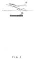
- FIG. 1 illustrates a tilt of a palm ST when performing authentication.
- a biometric authentication device 100 according to Embodiment 1 is a palm vein authentication device in which a target for biometric authentication is the palm veins, and is an example of a three-dimensional shape measuring device. It is assumed that the biometric authentication device 100 according to Embodiment 1 is not provided with a guiding member that guides a position of a hand. Therefore, when performing authentication, the palm ST may fail to be horizontal to the biometric authentication device 100 and may tilt, as illustrated in FIG. 1.
- FIG. 1 illustrates an example in which an angle that is formed by a horizontal line (a broken line in FIG. 1 ) orthogonal to an optical axis of the biometric authentication device 100 (optical axes of a light source and an image sensor) and the palm ST is ⁇ i.
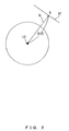
- FIG. 2 is a diagram explaining a relationship between a luminance value I (X) and a distance D(X) in a case in which a light source LS is a point light source.
- the luminance value I(X) is a luminance value at a point X on a subject ST in a captured image, as described above.
- the point X is defined by an image coordinate system with the center of the captured image as an origin.
- the distance D (X) is a distance between a position on the subject ST that corresponds to the point X and the light source LS, as described above. In this case, because the light source LS is a point light source, the luminance value I (X) is proportional to (1/D(X) 2 ).
- FIG. 3 is a diagram explaining a relationship between the luminance value I(X) and the distance D(X) in the biometric authentication device 100.
- An actual biometric authentication device 100 includes a plurality of light sources LS provided on a board BD, and a light guide TM, as illustrated in FIG. 3 .
- the subject ST is illuminated with illumination light IL from the plurality of light sources LS in such a way that the light guide TM makes the distribution of the illumination intensity uniform.
- An arrow drawn with a broken line in FIG. 3 represents internal reflection generated by internal parts or the like.
- the actual biometric authentication device 100 includes the plurality of light sources LS, and is influenced by internal reflection. Namely, the actual biometric authentication device 100 has a great deviation from the point light source model, and therefore the luminance value I(X) is not always proportional to (1/D(X) 2 ).
- a coefficient ⁇ is a coefficient that represents distance dependency of the illumination intensity, and an appropriate value is set for the coefficient ⁇ in accordance with conditions of a sensor and the subject ST, as described later in detail.
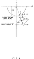
- FIG. 4 illustrates an optical model used in Non-Patent Document 3. It is assumed that an imaging device is a pinhole camera model and that the subject ST has a complete diffusion reflection characteristic. It is also assumed that an illumination intensity decreases in inverse proportion to the square of a distance between a light source LS and the subject ST, and that the light source LS is located at the center of a lens (an origin O in FIG. 4 ).
- An element surface (an image plane) in which an image sensor exists that is, a luminance value at a point m in FIG. 4 is usually used, while in Non-Patent Document 3, a luminance value at a point m' on a circle having a radius f with the origin O as a center is used.
- the radius f is the shortest distance between the center of the lens (the origin O) and the element surface, namely, a focal distance
- the point m' is an intersection of a line connecting the origin O with the point m and the circle having the radius f as the origin O as a center.
- the object surface S of the subject ST can be expressed by the following expression 3.
- X (xi, yi) is established
- S(X) is an intersection of the line connecting the origin O with the point m and the object surface S of the subject ST.
- S S X : X ⁇ ⁇
- the point m' can be expressed by the following expression 5 by using expression 4.
- m ⁇ f X 2 + f 2 m
- the luminance I(X) can be expressed by the following expression 7 under the assumption that the illumination intensity decreases in inverse proportion to the square of the distance between the light source LS and the subject ST.
- the constant I 0 is not considered.
- ⁇ i in expression 7 is an angle that is formed by a normal vector n (X) of the obj ect surface S at S (X) and a unit vector L (S(X)) in a direction of the light source LS (the origin O), and D (X) in expression 7 is a distance from the light source LS (the origin O) to the point S(X) on the object surface S.
- I X cos ⁇ i D X ⁇
- n(X) of the object surface S at the point S (X) can be expressed by the following expression 8.
- V represents a differential operator
- "•" represents an inner product.
- n X f ⁇ u X - fu X X 2 + f 2 X , ⁇ u X ⁇ X + fu X X 2 + f 2 f
- the unit vector L (S (X)) in a direction of the light source LS (the origin O) at the point S (X) can be expressed by the following expression 9 by using coordinates of the point m.
- L S X 1 X 2 + f 2 - X
- f cos ⁇ i can be obtained from an inner product of a unit normal vector n(X)/
- cos ⁇ i L S X ⁇ n X n X
- the luminance value I(X) can be expressed by the following expression 13, by using expression 11.
- I X fu X n X X 2 + f 2 ⁇ 1
- D X 2 u X n X X + f 2 f 2 ⁇ 1 f 2 u X 2
- Q(X) is defined by the following expression 14.
- Q X f 2 X 2 + f 2
- a process of calculating a three-dimensional shape of a subject ST in a model in which a distance-dependent coefficient of 2.0 employed in Embodiment 1 is generalized into a coefficient ⁇ (hereinafter referred to as a "distance-dependent variable model") is described next.
- the luminance value I (X) can be expressed by the following expression 22 under the assumption that the illumination intensity decreases in inverse proportion to the ⁇ -th power of the distance between the light source LS and the subject ST.
- I 0 is not considered, similarly to the case described in Non-Patent Document 3.
- I X cos ⁇ i D X ⁇
- u(X) and ⁇ (X) has a relationship expressed by the following expression 28.
- u X e ⁇ v X ⁇
- u X ⁇ e ⁇ v X ⁇ X
- ⁇ ln b
- Q'(X), J'(X), and p are defined by the following expressions 30, 31, and 32, respectively.
- Q'(X) can be expressed by the following expression 35.
- Q ⁇ X ⁇ 2 f 2 X 2 + f 2
- FIG. 5 is a diagram explaining a height z of a subject ST and a coefficient ⁇ according to Embodiment 1.
- W in FIG. 5 represents a portion in which rays of illumination light IL emitted from two light sources LS of the biometric authentication device 100 overlap each other.
- the illumination light IL illuminating the subject ST can be approximated to the illumination light IL from one of the light sources LS, as illustrated in FIG. 5 . Namely, ⁇ ⁇ 2 is established.
- the illumination light IL illuminating the subject ST is approximated to rays of the illumination light IL from the two light sources LS, as illustrated in FIG. 5 . Namely, ⁇ ⁇ 2 is established.
- an appropriate value of the coefficient ⁇ varies according to the height z of the subject ST. Accordingly, in Embodiment 1, an accuracy in measuring a three-dimensional shape of the subject ST by using the SFS technique can be improved by changing the coefficient ⁇ according to an average height of the subject ST.
- FIG. 6 is a functional block diagram illustrating an exemplary configuration of the biometric authentication device 100 according to Embodiment 1.
- the biometric authentication device 100 according to Embodiment 1 includes an imaging unit 10, a distance sensor 20, a storage 30, and a controller 40, as illustrated in FIG. 6 .
- the imaging unit 10 includes an image sensor such as a Complementary Metal Oxide Semiconductor (CMOS) image sensor, a lighting device such as a Light Emitting Diode (LED), and the like.
- CMOS Complementary Metal Oxide Semiconductor
- LED Light Emitting Diode
- the imaging unit 10 illuminates the subject (in Embodiment 1, a palm) ST under the control of the controller 40, and images the subject ST with the subject ST illuminated.
- the imaging unit 10 then stores a captured image in a data area of the storage 30 under the control of the controller 40.
- the distance sensor 20 is sensor that measures the height z of the subject ST.
- the height z of the subject ST may be measured in a well-known method other than a method using the distance sensor 20.
- An example of such a method is a method proposed, for example, in Patent Document 1.
- the method proposed in Patent Document 1 is a method using a spot image for measuring a height. In the method, the subject ST is illuminated with illumination light IL narrowed in a beam shape, and a height z from a spot position to the subject ST is calculated.
- the storage 30 includes, for example, a Random Access Memory (RAM), a Read Only Memory (ROM), a flash memory, and the like.
- the storage 30 functions as a work area of, for example, a Central Processing Unit (CPU) included in the controller 40, a program area in which various programs are stored such as an operation program for controlling the entirety of the biometric authentication device 100, and a data area in which various types of data are stored.
- CPU Central Processing Unit
- the storage 30 also functions as a coefficient storage 31 and a database 32, as illustrated in FIG. 6 .
- the coefficient storage 31 is a storage that stores information indicating a relationship between a height zr of a reference object RF and a coefficient ⁇ (zr).
- the reference object RF is a plane body for which a reflectance is constant and known.
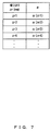
- FIGS. 7 and 8 illustrate examples of information that is stored in the coefficient storage 31 according to Embodiment 1 and that indicates a relationship between the height zr of the reference object RF and the coefficient ⁇ (zr).
- the information indicating the relationship between the height zr of the reference object RF and the coefficient ⁇ (zr) is an approximate function h(zr) indicating the relationship between the height zr of the reference object RF and the coefficient ⁇ (zr).
- a method for obtaining the relationship between the height zr of the reference object RF and the coefficient ⁇ (zr) is described next.
- three expressions relating to the coefficient ⁇ as expressed by the following expression 39 can be derived from expression 38.
- a coefficient ⁇ (zr) that generates the smallest error for the three expressions in expression 39 can be obtained, for example, in the least squares method.
- the database 32 stores data needed for biometric authentication.
- the database 32 stores feature data of an image for registration used for collation.
- the feature data of the image for registration is feature data that is extracted from an image captured when registering biological data of a user by a feature extracting unit 42 (described later in detail).
- the controller 40 includes, for example, a CPU and the like, and executes an operation program stored in the program area of the storage 30 so as to realize functions of a three-dimensional shape measurement processing unit 41, a feature extracting unit 42, and a collation processing unit 43.
- the controller 40 also executes the operation program so as to perform processes such as a control process for controlling the entirety of the biometric authentication device 100 or an authentication process described later in detail.
- the three-dimensional shape measurement processing unit 41 is described later in detail. Functions of the feature extracting unit 42 and the collation processing unit 43 are described first.
- the feature extracting unit 42 extracts feature data from a captured image in a well-known method. More specifically, in registering biological data, the feature extracting unit 42 extracts feature data from a captured image stored in the data area of the storage 30, and registers the extracted feature data in the database 32.
- the feature extracting unit 42 extracts feature data from a captured image in which a posture of the subject ST has been corrected by a posture correcting unit 41F described later in detail, and outputs the extracted feature data to the collation processing unit 43.
- the collation processing unit 43 collates feature data for collation that has been input from the feature extracting unit 42 with feature data for registration that has been registered in the database 32, and stores a collation result in the data area of the storage 30.
- the collation result is, for example, a similarity ratio between the feature data for collation and the feature data for registration.
- FIG. 9 is a functional block diagram illustrating an exemplary configuration of the three-dimensional shape measurement processing unit 41 according to Embodiment 1.
- the three-dimensional shape measurement processing unit 41 measures a three-dimensional shape of the subject ST, and performs a process of correcting a posture (angle) of the subject ST in a captured image in accordance with a measurement result.
- the three-dimensional shape measurement processing unit 41 functions as a distance measuring unit 41A, a reflectance estimating unit 41B, a coefficient setting unit 41C, a luminance value correcting unit 41D, a three-dimensional shape measuring unit 41E, and a posture correcting unit 41F, as illustrated in FIG. 9 .
- the distance measuring unit 41A controls the distance sensor 20 so as to detect a height z from the light source LS to the subject ST. If the distance sensor 20 can detect heights z in a plurality of positions on the subject ST, an average of the heights z is obtained, and the obtained average height is determined to be a height of the subject ST.
- the reflectance estimating unit 41B estimates a reflectance R f of the subject ST, and performs correction to cancel the reflectance R f peculiar to the subject ST.
- the reflectance R f of the subject ST varies according to users, for example, when the subject ST is a palm ST. Therefore, the reflectance R f of the subject ST is estimated, and correction to cancel the reflectance R f peculiar to the subject ST is performed on a luminance value Is(X) of a captured image.
- the subject ST can be regarded as an object having the same reflectance as that of the reference object RF. Accordingly, a three-dimensional shape of the subject ST can be stably measured by using the SFS technique, regardless of the type of the subject ST.
- the reflectance estimating unit 41B first obtains the luminance value Is(X) of a captured image at a point X that corresponds to a position on the subject ST in which the height z of the subject ST is detected by the distance sensor 20. The reflectance estimating unit 41B then obtains a luminance value Ir, z (X) at a point X of the reference object RF at the same height as the height z of the subject ST.
- the reflectance estimating unit 41B estimates the reflectance R f of the subject ST in a case in which the reflectance of the reference object RF is assumed to be "1.0", in accordance with the following expression 40.
- R f Is X Ir , z X
- the reflectance estimating unit 41B performs correction to cancel the reflectance R f peculiar to the subject ST in accordance with the following expression 41, and outputs the corrected luminance value Is' (X) to the luminance value correction unit 41D.
- Is ⁇ X Is X / R f
- the luminance value Ir,z(X) can be obtained by storing captured images of the reference object RF that have been captured, for example, at prescribed height intervals in the data area of the storage 30.
- the reflectance estimating unit 41B can estimate the luminance value Ir,z(X) at the point X of the reference object RF at the same height as the height z of the subject ST, for example, with linear interpolation.
- the luminance value Ir,z(X) can be obtained (calculated) by storing a coefficient of a function for calculating the luminance value Ir,z(X) in the data area of the storage 30.
- a function indicating an approximate curve can be obtained by performing curve approximation on the basis of luminance values of captured images of the reference object RF, for example, at three different heights z1, z2, and z3.
- the function indicating the approximate curve can be expressed, for example, by the following expression 42.
- Dr, z (X) in expression 42 is a distance from the light source LS to a position that corresponds to the point X of the reference object RF in a case in which the reference object RF is located at the height z.
- A(X), B(X), and C(X) in expression 42 are coefficients of a function indicating an approximate curve for the point X of the reference object RF.
- the function indicating the approximate curve fails to be expressed by using only the term (Dr, z(X) -2 ). Accordingly, a function including the coefficients B(X) and C(X) is assumed to be a function indicating the approximate curve.
- f is a focal distance.
- Luminance values Ir,z 1 (X), Ir,z 2 (X), and Ir,z 3 (X) at the point X of the reference object RF at three different heights z1, z2, and z3 can be calculated according to the following expression 45 on the basis of expression 42.
- the distances Dr,z 1 (X), Dr,z 2 (X), and Dr,z 3 (X) in expression 45 can be calculated from expressions 43 and 44 by applying the height of the reference obj ect RF when the point X on the captured image and the focal distance f are determined. Accordingly, expression 45 includes three simultaneous equations that correspond to three unknown coefficients A(X), B(X), and C(X). Therefore, the coefficients A(X), B(X), and C (X) can be obtained by solving these simultaneous equations.
- the reflectance estimating unit 41B can obtain (calculate) the luminance value Ir, z (X) at the point X (pixel X) of the reference object RF at the same height as the height z of the subject ST.
- FIG. 10 illustrates an example of information in which a set of coefficients (A(X), B(X), and C(X)) is associated with each of the pixels stored in the storage 30 according to Embodiment 1.
- the coefficient setting unit 41C sets a coefficient ⁇ that is used to perform a process of correcting a luminance value and to measure a three-dimensional shape of the subject ST by using the SFS technique according to various conditions such as the height z of the subject ST, the size of a sensor, and the like. In Embodiment 1, the coefficient setting unit 41C sets the coefficient ⁇ according to the height z of the subject ST.
- the coefficient setting unit 41C specifies a coefficient ⁇ that corresponds to the height z of the subject ST measured by the distance measuring unit 41A on the basis of the information that has been stored in the coefficient storage 31 and that indicates the relationship between the height zr and the coefficient ⁇ (zr), and sets the specified coefficient ⁇ .
- the coefficient setting unit 41C estimates the coefficient ⁇ of the height z of the subject ST, for example, with linear interpolation, and sets the estimated coefficient ⁇ .
- the luminance value correcting unit 41D further corrects the luminance value Is' (X) input by the reflectance estimating unit 41B, by using the luminance value Ir, z (X) of the reference obj ect RF, in order to reduce influence of peripheral darkening.
- the luminance value correcting unit 41D obtains (calculates) the luminance value Ir,z(X) at the point X of the reference object RF at the height z of the subject ST in the method above. Then, the luminance value correcting unit 41D calculates a correction coefficient ⁇ (X) for each of the points X on the captured image in accordance with the following expression 46.
- P is a constant
- the coefficient ⁇ is the coefficient ⁇ set by the coefficient setting unit 41C.
- ⁇ x P Ir , z X Dr , z X ⁇
- the luminance value correcting unit 41D further corrects the luminance value Is'(X) in accordance with the following expression 47, and outputs the corrected Is"(X) to the three-dimensional shape measuring unit 41E.
- Is ⁇ X Is ⁇ X ⁇ X
- the coefficient k(X) represents peripheral darkening in a cases in which the luminance value Ir, z(X) at the point X of the reference object RF is proportional to (1/Dr,z(X) ⁇ ). Accordingly, influence of peripheral darkening can be cancelled by employing the reciprocal of peripheral darkening for the correction coefficient ⁇ (X). As described above, an accuracy in measuring the three-dimensional shape of the subject ST can be improved by removing a factor that is not considered in the conventional SFS technique, such as peripheral darkening.
- k X Ir , z X Dr , z X ⁇
- the three-dimensional shape measuring unit 41E calculates a differential equation of the distance-dependent variable model above by using the luminance value Is"(X) input by the luminance value correcting unit 41D and the coefficient ⁇ set by the coefficient setting unit 41C so as to measure the three-dimensional shape of the subject ST (a distance from the light source LS to a position of a three-dimensional coordinate system that corresponds to the point X on the captured image) .
- the posture correcting unit 41F corrects a posture of the subject ST in the captured image on the basis of the three-dimensional shape of the subject ST measured by the three-dimensional shape measuring unit 41E. More specifically, the posture correction unit 41F calculates an angle of a tilt of the subject ST to a reference plane on the basis of the three-dimensional shape of the subject ST measured by the three-dimensional shape measuring unit 41E.
- the reference plane is a plane parallel to a horizontal line drawn with a broken line in FIG. 1 , as an example.
- the angle of the tile of the subject ST to the reference plane can be obtained, for example, by projecting the three-dimensional shape of the subject ST measured by the three-dimensional shape measuring unit 41E to two dimensions and performing linear approximation on a two-dimensional projection.
- a tilt of the subject ST to an XZ plane by projecting the three-dimensional shape of the subject ST onto the XZ plane and performing linear approximation on a projection on the XZ plane.
- a tilt of the subject ST to a YZ plane by projecting the three-dimensional shape of the subject ST onto the YZ plane and performing linear approximation on a projection on the YZ plane.
- An angle of a tilt of the subject ST to the reference plane can be obtained by obtaining the tilts of the subject ST to the XZ plane and the YZ plane.
- the angle of the tilt of the subject ST to the reference plane may be obtained by directly applying a plane equation to the three-dimensional shape of the subject ST.
- the posture correcting unit 41F corrects the posture of the subject ST in the captured image in such a way that the angle of the tilt of the subject ST to the reference plane is "0", namely in such a way that the subject ST is parallel to the reference plane.
- the posture correcting unit 41F then outputs the corrected captured image to the feature extracting unit 42.
- FIG. 11 is an exemplary flowchart explaining the flow of the authentication process according to Embodiment 1.
- the controller 40 controls the imaging unit 10 to image the subject ST with the subject ST illustrated so as to obtain a capture image, and stores the obtained captured image in the data area of the storage 30 (step S001) .
- the three-dimensional shape measurement processing unit 41 performs a three-dimensional shape measuring process so as to measure a three-dimensional shape of the subject ST, and corrects a posture of the subject ST in the captured image (step S002).
- the feature extracting unit 42 extracts feature data from the captured image in which the posture of the subject ST has been corrected (step S003).
- the collation processing unit 43 collates the feature data extracted in step S003 with feature data for registration that is stored in the database 32, and stores a collation result in the data area of the storage 30 (step S004). Then, the process is finished.
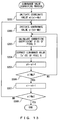
- FIG. 12 is an exemplary flowchart explaining the flow of the three-dimensional shape measuring process according to Embodiment 1.
- the three-dimensional shape measuring process is a process that corresponds to the process of step S002 in the authentication process.
- the distance measuring unit 41A controls the distance sensor 20 to detect the height z of the subject ST (step S101).
- the reflectance estimating unit 41B estimates a reflectance R f of the subject ST according to expression 40 described above, and performs correction to cancel the reflectance R f peculiar to the subject ST from the luminance value Is(X) at the point X of the captured image according to expression 41 described above (step S102).
- the coefficient setting unit 41C sets a coefficient ⁇ that corresponds to the height z of the subject ST (step S103).
- the luminance value correcting unit 41D performs a luminance value correcting process so as to perform correction to cancel influence of peripheral darkening (step S104).
- the three-dimensional shape measuring unit 41E calculates a differential equation of the distance-dependent variable model by using the luminance value Is"(X) after correction performed by the luminance value correcting unit 41D and the coefficient ⁇ so as to measure the three-dimensional shape of the subject ST (step S105).
- the posture correcting unit 41F corrects the posture of the subject ST in the captured image in such a way that the posture of the subject ST is parallel to the reference plane, on the basis of the three-dimensional shape of the subject ST (step S106). Then, this process is finished, and the process moves on to the process of step S003 in the authentication process.
- FIG. 13 is an exemplary flowchart explaining the flow of the luminance value correcting process according to Embodiment 1.
- the luminance value correcting process is a process that corresponds to the process of step S104 in the three-dimensional shape measuring process.
- the number of pixels of a captured image is assumed to be (2Mx + 1) x (2My + 1).
- the luminance value correcting unit 41D calculates a correction coefficient ⁇ (X) of the pixel X according to expression 46 (step S203), and corrects the luminance value Is'(X) of the pixel X (step S204).
- the luminance value correcting unit 41D increments the coordinate value yi of the pixel X (step S205), and determines whether the incremented coordinate value yi is greater than My (step S206). When the luminance value correcting unit 41D determines that the incremented coordinate value yi is less than or equal to My (step S206: NO), the process returns to the process of step S203, and the processes described above are repeated.
- the luminance value correcting unit 41D determines that the incremented coordinate value yi is greater than My (step S206: YES)
- the luminance value correcting unit 41D increments the coordinate value xi of the pixel X (step S207).
- the luminance value correcting unit 41D determines whether the incremented coordinate value xi is greater than Mx (step S208).
- step S208: NO the process returns to the process of step S202, and the processes described above are repeated.
- step S208: YES the luminance value correcting unit 41D determines that the incremented coordinate value xi is greater than Mx
- the biometric authentication device 100 sets the coefficient ⁇ according to the height z of the subject ST. By doing this, an accuracy in measuring the three-dimensional shape of the subject ST measured by using the SFS technique can be improved, even when a relationship between a luminance value and a distance deviates from an ideal point light source model in which the luminance value is inversely proportional to the square of the distance, due to the height z of the subject ST.
- the biometric authentication device 100 estimates the reflectance R f of the subject ST on the basis of the luminance value of the reference object RF and the luminance value of the captured image, and corrects the luminance value of the captured image in such a way that the reflectance of the subject ST is almost equal to the reflectance of the reference object RF.
- the subject ST can be regarded as an object having the same reflectance as that of the reference object RF, and therefore the three-dimensional shape of the subject ST can be stably measured by using the SFS technique, regardless of the type of the subject ST.
- the biometric authentication device 100 performs, on the luminance value of the captured image, correction to remove influence of peripheral darkening on the luminance value of the captured image.
- An accuracy in measuring the three-dimensional shape of the subject ST can be improved by removing a factor that is not considered in the conventional SFS technique, such as peripheral darkening.
- the biometric authentication device 100 corrects a tilt of the subject ST in a captured image on the basis of a measured three-dimensional shape of the subject ST. By doing this, a posture of the subject ST in the captured image can be corrected to the same posture as the posture in a captured image from which feature data for registration has been extracted, and therefore an authentication accuracy can be improved.
- Embodiment 1 a scheme for setting the coefficient ⁇ according the height z of the subject ST has been described.
- Embodiment 2 a case is assumed in which a guiding member that guides a position of the subject ST is provided in a biometric authentication device 100.
- the guiding member is provided in the biometric authentication device 100, the height z of the subject ST is fixed, but a position of the subject ST in the xy direction varies within a prescribed range, and is not fixed.
- a scheme for setting the coefficient ⁇ according to the position of the subject ST in the xy direction in a case in which the height z of the subject ST is fixed is described.
- the coefficient ⁇ is set according to the position of the subject ST in the xy direction as described above because, in a case in which the biometric authentication device 100 includes a plurality of light sources LS, the number of light sources LS that illuminate the subject ST may vary depending on the position of the subject ST in the xy direction.
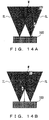
- FIGS. 14A and 14B are diagrams explaining a relationship between a position of the subject ST on a horizontal plane (the position of the subject ST in the xy direction) and a coefficient ⁇ according to Embodiment 2.
- illumination light IL that illuminates the subject ST having a height z can be approximated to illumination light IL from one light source LS. Namely, ⁇ ⁇ 2 is estimated.
- the subject ST is located in a portion in which rays of illumination light IL are overlapping each other, and therefore illumination light IL that illuminates the subject ST can be approximated to rays of illumination light IL from two light sources LS. Namely, ⁇ ⁇ 2 is established.
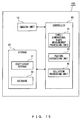
- FIG. 15 is a functional block diagram illustrating an exemplary configuration of a biometric authentication device 100 according to Embodiment 2.
- FIG. 16 is a functional block diagram illustrating an exemplary configuration of a three-dimensional shape measurement processing unit 41 according to Embodiment 2.
- a basic configuration of the biometric authentication device 100 according to Embodiment 2 is the same as the configuration according to Embodiment 1. However, the configuration according to Embodiment 2 is different from that according to Embodiment 1 in that the distance sensor 20 is not included, as illustrated in FIG. 15 .
- the configuration according to Embodiment 2 is also different from that according to Embodiment 1 in that the three-dimensional shape measurement processing unit 41 does not include the distance measuring unit 41A, as illustrated in FIG. 16 .
- the coefficient storage 31 stores a function F ⁇ (X) for calculating a coefficient ⁇ that corresponds to a point X (pixel X) in a captured image.
- the function F ⁇ (X) is a function for calculating a coefficient ⁇ that corresponds to each of the points X on the subject ST included in the captured image.
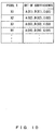
- the coefficient storage 31 may store information in which the coefficient ⁇ is associated with each of the pixels, as illustrated in FIG. 17 , instead of the function F ⁇ (X).
- FIG. 17 illustrates an example of information that is stored in the coefficient storage 31 according to Embodiment 2 and in which the coefficient ⁇ is associated with each of the pixels.
- the coefficient setting unit 41C sets the coefficient ⁇ according to a position of the subject ST in the xy direction in Embodiment 2. Namely, the coefficient setting unit 41C sets the coefficient ⁇ according to a position of the subject ST in a captured image. More specifically, the coefficient setting unit 41C specifies a region T in which the subject ST is located in the captured image in a well-known method, and calculates a mean value ⁇ AVE of the coefficient ⁇ that corresponds to each of the pixels in the region T according to the following expression 49.
- N T is the number of pixels in the region T in which the subject ST is located.
- Expression 49 is an example in a case in which the coefficient storage 31 stores the function F ⁇ (X).
- ⁇ AVE ⁇ X ⁇ T F ⁇ X / N T
- the coefficient setting unit 41C sets the calculated mean value ⁇ AVE to be the coefficient ⁇ used to perform the luminance value correcting process and to measure the three-dimensional shape of the subject ST by using the SFS technique.
- the biometric authentication device 100 sets the coefficient ⁇ on the basis of the position of the subject ST in the xy direction. By doing this, even when a relationship between a luminance value and a distance deviates from an ideal point light source model in which the luminance value is inversely proportional to the square of the distance due to a positional deviation of the subject ST in the xy direction, an accuracy in measuring the three-dimensional shape of the subject ST by using the SFS technique can be improved.
- Embodiment 1 a scheme for setting the coefficient ⁇ in accordance with the height z of the subj ect ST has been described.
- Embodiment 2 a scheme for setting the coefficient ⁇ in accordance with the position of the subject ST in the xy direction in a case in which the height z of the subject ST is fixed has been described.
- Embodiment 3 a scheme for setting the coefficient ⁇ in accordance with the height z of the subject ST and the position in the xy direction is described.
- a basic configuration of a biometric authentication device 100 according to Embodiment 3 is the same as the configuration in Embodiment 1. However, there are slight differences between the configuration according to Embodiment 3 and the configuration according to Embodiment 1 in functions of a coefficient storage 31 and a coefficient setting unit 41C.
- a coefficient storage 31 stores a function F ⁇ (X,z) for calculating a coefficient ⁇ that corresponds to a set of a height z of a subject ST and a point X (pixel X) on a captured image.
- a coefficient setting unit 41C sets the coefficient ⁇ in accordance with the height z and the position in the xy direction of the subject ST. More specifically, the coefficient setting unit 41C specifies a region T in which the subject ST is located in the captured image in a well-known method, and calculates a mean value ⁇ AVE of the coefficient ⁇ that corresponds to each of the pixels in the region T according to the following expression 50. In this case, a height z measured by a distance measuring unit 41C is used for the height z of the subject ST.
- ⁇ AVE ⁇ X ⁇ T F ⁇ X z / N T
- the coefficient setting unit 41C sets the calculated mean value ⁇ AVE to be a coefficient ⁇ used to perform a luminance value correcting process and to measure a three-dimensional shape of the subject ST by using the SFS technique.
- the biometric authentication device 100 sets the coefficient ⁇ on the basis of the height z and the position in the xy direction of the subject ST. By doing this, even when a guiding member that guides the position of the subject ST is not provided in the biometric authentication device 100, the coefficient ⁇ can be set in consideration of both the height z and the position in the xy direction of the subject ST.
- the biometric authentication device 100 itself includes the database 32, and has a function of collating feature data for collation with feature data for registration that has been registered in the database 32.
- a biometric authentication system 1 that is configured of one or more biometric authentication sensors 70 and a server computer 80 is described as an example. All of Embodiments 1 to 3 can be applied to the biometric authentication system 1, but a case in which Embodiment 1 is applied to the biometric authentication system 1 is now described.
- FIG. 18 illustrates an exemplary configuration of the biometric authentication system 1 according to Embodiment 4.
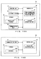
- FIG. 19A is a functional block diagram illustrating an exemplary configuration of the biometric authentication sensor 70 in the biometric authentication system 1 according to Embodiment 4, and
- FIG. 19B is a functional block diagram illustrating an exemplary configuration of the server computer 80.
- the one or more biometric authentication sensors 70 are communicably connected to the server computer 80 via a network NW, as illustrated in FIG. 18 .
- the biometric authentication sensor 70 according to Embodiment 4 includes an imaging unit 10, a distance sensor 20, a storage 30, a controller 40, and a communication unit 50, as illustrated in FIG. 19A .
- Abasic configuration of the biometric authentication sensor 70 according to Embodiment 4 is the same as the configuration of the biometric authentication device 100 according to Embodiment 1.
- the biometric authentication sensor 70 according to Embodiment 4 is different from the biometric authentication device 100 according to Embodiment 1 in that the storage 30 of the biometric authentication sensor 70 does not function as the database 32 and that the controller 40 does not function as the collation processing unit 43. This is because a collation process is performed on the side of the server computer 80 in Embodiment 4.
- the biometric authentication sensor 70 according to Embodiment 4 is different from the biometric authentication device 100 according to Embodiment 1 in that the communication unit 50 is included.
- the communication unit 50 includes, for example, a communication module and the like, and performs communication with the server computer 80.
- the communication unit 50 transmits feature data extracted by a feature extracting unit 42 to the server computer 80.
- the communication unit 50 receives a collation result transmitted from the server computer 80. The received collation result is stored in the data area of the storage 30 under the control of the controller 40.
- the server computer 80 includes a communication unit 81, a storage 82, and a controller 83, as illustrated in FIG. 19B .
- the communication unit 81 includes, for example, a communication module and the like, and performs communication with each of the biometric authentication sensors 70 in the biometric authentication system 1. As an example, the communication unit 81 receives feature data transmitted from the biometric authentication sensor 70. As another example, the communication unit 81 transmits a collation result of a collation processing unit 83A to the biometric authentication sensor 70 that is a transmitter of the feature data.
- the storage 82 includes, for example, a RAM, a ROM, a Hard Disk Drive (HDD), and the like.
- the storage 82 functions as a work area of, for example, a CPU included in the controller 83 , a program area in which various programs such as an operation program for controlling the entirety of the server computer 80 are stored, and a data area in which various types of data are stored.
- the storage 82 also functions as a database 82A, as illustrated in FIG. 19B .
- the controller 83 includes, for example, a CPU and the like, and executes the operation program stored in the program area of the storage 82 so as to realize a function of the collation processing unit 83A, as illustrated in FIG. 19B .
- the controller 40 executes the operation program so as to perform processes such as a control program for controlling the entirety of the server computer 80.
- FIG. 20 illustrates an example of a hardware configuration of the biometric authentication device 100 (or the biometric authentication sensor 70) according to the embodiments.
- the biometric authentication device 100 illustrated in FIG. 6 (or the biometric authentication sensor 70 illustrated in FIG. 19A ) may be realized by various types of hardware illustrated in FIG. 20 , for example.
- the biometric authentication device 100 (or the biometric authentication sensor 70) includes a CPU 201, a RAM 202, a ROM 203, a flash memory 204, a camera interface 205 that connects an imaging device, an equipment interface 206 that connects the distance sensor 20 or the like, a communication module 207, and a reading device 208, and these pieces of hardware are connected to each other via a bus 209.
- the CPU 201 loads an operation program stored, for example, in the flash memory 204 onto the RAM 202, and performs various processes while using the RAM 202 as a working memory.
- the CPU 201 can realize respective function units of the controller 40 illustrated in FIG. 6 and the like by executing the operation program.
- the processes above may be performed by storing an operation program for performing the operations above in a computer-readable recording medium 210 such as a flexible disk, a Compact Disk-Read Only Memory (CD-ROM), a Digital Versatile Disk (DVD), or a Magneto Optical disk (MO) and distributing the operation program, and reading the operation program by the reading device 208 of the biometric authentication device 100 (or the biometric authentication sensor 70) and installing the operation program onto a computer.
- a computer-readable recording medium 210 such as a flexible disk, a Compact Disk-Read Only Memory (CD-ROM), a Digital Versatile Disk (DVD), or a Magneto Optical disk (MO)
- a computer-readable recording medium 210 such as a flexible disk, a Compact Disk-Read Only Memory (CD-ROM), a Digital Versatile Disk (DVD), or a Magneto Optical disk (MO)
- a computer-readable recording medium 210 such as a flexible disk, a Compact Disk-Read Only
- the biometric authentication device 100 may include a storage such as a Content Addressable Memory (CAM), a Static Random Access Memory (SRAM), or a Synchronous Dynamic Random Access Memory (SDRAM) .
- CAM Content Addressable Memory
- SRAM Static Random Access Memory
- SDRAM Synchronous Dynamic Random Access Memory
- a hardware configuration of the biometric authentication device 100 may be different from the configuration illustrated in FIG. 20 , and hardware having a standard or type other than that illustrated in FIG. 20 can be employed for the biometric authentication device 100 (or the biometric authentication sensor 70).
- respective function units of the controller 40 of the biometric authentication device 100 may be realized by a hardware circuit.
- the respective function units of the controller 40 illustrated in FIG. 6 or the like may be realized by a reconfigurable circuit such as a Field Programmable Gate Array (FPGA), an Application Specific Integrated Circuit (ASIC), or the like, instead of the CPU 201.
- FPGA Field Programmable Gate Array
- ASIC Application Specific Integrated Circuit
- these function units may be realized by both the CPU 201 and the hardware circuit.
Landscapes
- Engineering & Computer Science (AREA)
- Physics & Mathematics (AREA)
- General Physics & Mathematics (AREA)
- Health & Medical Sciences (AREA)
- Life Sciences & Earth Sciences (AREA)
- Theoretical Computer Science (AREA)
- Heart & Thoracic Surgery (AREA)
- Public Health (AREA)
- Medical Informatics (AREA)
- Molecular Biology (AREA)
- Surgery (AREA)
- Animal Behavior & Ethology (AREA)
- General Health & Medical Sciences (AREA)
- Biophysics (AREA)
- Veterinary Medicine (AREA)
- Biomedical Technology (AREA)
- Pathology (AREA)
- Computer Vision & Pattern Recognition (AREA)
- Multimedia (AREA)
- Length Measuring Devices By Optical Means (AREA)
- Measurement Of The Respiration, Hearing Ability, Form, And Blood Characteristics Of Living Organisms (AREA)
Abstract
Description
- The embodiments discussed herein are related to measuring of a three-dimensional shape.
- A technology for measuring a three-dimensional shape of a subject on the basis of a captured image. Such a technology is employed in various technical fields. One example is a biometric authentication device such as a palm vein authentication device.
- In the palm vein authentication device, when imaging biological data to be registered, a position of a hand, which is an example of the subject, is guided by a well-known guiding member or the like. However, there are cases in which a guiding member that guides the position of the hand when performing collation is not provided. When biological data of a hand that is not guided by a guiding member is imaged, a great difference may be generated between registration data and collation data due to a difference in the position of the hand, a tilt of the hand, or the like, and a success rate of personal authentication may be reduced.
- One example of a method for solving the problem above is a method for measuring a posture such as a tilt of a hand and making correction to cancel deviation in the posture of the hand when performing collation. In this method, the posture of the hand can be detected by using a plurality of distance sensors so as to measure a distance from the respective distance sensors to a corresponding portion of the hand. However, in order to improve an accuracy in measuring the posture of the hand, a large number of distance sensors need to be used. Therefore, a cost for a biometric authentication device increases, and a size of the biometric authentication device also increases. Further, when the biometric authentication device has physical restrictions on a size or the like, it is very difficult to arrange the large number of distance sensors within the restrictions while maintaining a prescribed accuracy or more in measuring the posture of the hand.
- Meanwhile, the Shape From Shading (SFS) technique for measuring a three-dimensional shape of a subject on the basis of an luminance value distribution of an image of a subject that is captured while the subject is being irradiated with illumination light is known (see, for example, Non-Patent Documents 1-3). By employing the SFS technique to measure a posture of a hand, distances from a light source to a large number of points can be measured without using a large number of distance sensors, and the posture of the hand can be detected with a higher accuracy.
- [Patent Document 1]
Japanese Laid-open Patent Publication No. 2007-10346 - [Non-Patent Document 1] R. Kimmel et al., "Global Shape from Shading", CVGIP: Image Understanding, pp. 120-125, 1994
- [Non-Patent Document 2] R. Zhang et al., "Shape from Shading: A Survey", IEEE PAMI (Transactions on Pattern Analysis and Machine Intelligence), Vol. 21, No. 8, pp. 690-706, August 1999
- [Non-Patent Document 3] E. Prados et al., "Shape from Shading: a well-posed problem?", INRIA, No. 5297, pp. 1-55, August 2004
- It is an object in one aspect of the invention to provide a three-dimensional shape measuring device, a three-dimensional shape measuring method, and a program that enable an accuracy in measuring a three-dimensional shape of a subject to be improved even when a relationship between a luminance value and a distance deviates from an ideal point light source model in which the luminance value is inversely proportional to the square of the distance.
- A three-dimensional shape measuring device in one aspect of the invention is a three-dimensional shape measuring device that measures a three-dimensional shape of a subject included in a captured image, and includes setting means for setting a coefficient that is an index of a power in a model expression for making a luminance value of the captured image be proportional to an inverse of the power of a distance from a light source to a measurement point of the luminance value according to a prescribed condition, and measuring means for measuring the three-dimensional shape of the subject according to the luminance value of the captured image and the coefficient.
-
-
FIG. 1 illustrates a tilt of a palm when performing authentication. -
FIG. 2 is a diagram explaining a relationship between a luminance value and a distance in a case in which a light source is a point light source. -
FIG. 3 is a diagram explaining a relationship between a luminance value and a distance in a biometric authentication device. -
FIG. 4 illustrates an optical model used in Non-Patent Document 3. -
FIG. 5 is a diagram explaining a relationship between a height of a subject and a coefficient α according toEmbodiment 1. -
FIG. 6 is a functional block diagram illustrating an exemplary configuration of a biometric authentication device according toEmbodiment 1. -
FIG. 7 illustrates an example of information that is stored in a coefficient storage according toEmbodiment 1 and that indicates a relationship between a height of a reference object and a coefficient α. -
FIG. 8 illustrates another example of information that is stored in a coefficient storage according toEmbodiment 1 and that indicates a relationship between a height of a reference object and a coefficient α. -
FIG. 9 is a functional block diagram illustrating an exemplary configuration of a three-dimensional shape measurement processing unit according toEmbodiment 1. -
FIG. 10 illustrates an example of information in which a set of coefficients is associated with each of the pixels stored in a storage according toEmbodiment 1. -
FIG. 11 is an exemplary flowchart explaining a flow of an authentication process according toEmbodiment 1. -
FIG. 12 is an exemplary flowchart explaining a flow of a three-dimensional shape measuring process according toEmbodiment 1. -
FIG. 13 is an exemplary flowchart explaining a flow of a luminance value correcting process according toEmbodiment 1. -
FIGS. 14A and 14B are diagrams explaining a relationship between a position of a subject on a horizontal plane and a coefficient α according toEmbodiment 2. -
FIG. 15 is a functional block diagram illustrating an exemplary configuration of a biometric authentication device according toEmbodiment 2. -
FIG. 16 is a functional block diagram illustrating an exemplary configuration of a three-dimensional shape measurement processing unit according toEmbodiment 2. -
FIG. 17 illustrates an example of information in which a coefficient α is associated with each of the pixels stored in a coefficient storage according toEmbodiment 2. -
FIG. 18 illustrates an exemplary configuration of a biometric authentication system according to Embodiment 4. -
FIG. 19A is a functional block diagram illustrating an exemplary configuration of a biometric authentication sensor in a biometric authentication system according to Embodiment 4, andFIG. 19B is a functional block diagram illustrating an exemplary configuration of a server computer. -
FIG. 20 illustrates an example of a hardware configuration of a biometric authentication device according to the embodiments. - In a conventional SFS technique disclosed, for example, in Non-Patent Document 3, it is often assumed that an illumination intensity is inversely proportional to the square of a distance between a subject and a light source. More specifically, when a distance between a position that corresponds to a point X on a subject of a captured image and a light source is D(X), a luminance value I (X) at the point X is assumed to be obtained by the
following expression 1. Inexpression 1, θi is an angle formed by a sight line vector of a camera and a normal vector of the subject, and I0 is a constant.
-
Expression 1 for calculating the luminance value I(X) is a calculation expression in a case in which a light source is an ideal point light source, because the luminance value I(X) decreases according to (1/D(X)2). On the other hand, in an actual device such as a biometric authentication device, the luminance value I(X) is not always proportional to (1/D(X)2) due to the existence of a plurality of light sources, the influence of internal reflection, or the like. - In particular, a biometric authentication device corresponds to a proximity optical system in which an imaging device is close to a subject. As an example, in a palm vein authentication device, an authentication distance (a distance between an image sensor and a subject) is assumed to be a very short distance of about 5 cm. In such a proximity optical system, the luminance value I (X) often greatly deviates from the ideal point light source model, and there is a problem wherein, when the SFS technique is employed to measure a posture of a hand, a large error is generated. In particular, there is an advantage wherein, as a size (principally, a surface area) of a sensor of a biometric authentication device increases, distribution of an illumination intensity (a luminance value) becomes almost uniform, but deviation from a point light source model becomes great, and an error increases.
- Embodiments are described below with reference to the drawings.
-
FIG. 1 illustrates a tilt of a palm ST when performing authentication. Abiometric authentication device 100 according toEmbodiment 1 is a palm vein authentication device in which a target for biometric authentication is the palm veins, and is an example of a three-dimensional shape measuring device. It is assumed that thebiometric authentication device 100 according toEmbodiment 1 is not provided with a guiding member that guides a position of a hand. Therefore, when performing authentication, the palm ST may fail to be horizontal to thebiometric authentication device 100 and may tilt, as illustrated inFIG. 1. FIG. 1 illustrates an example in which an angle that is formed by a horizontal line (a broken line inFIG. 1 ) orthogonal to an optical axis of the biometric authentication device 100 (optical axes of a light source and an image sensor) and the palm ST is θi. -
FIG. 2 is a diagram explaining a relationship between a luminance value I (X) and a distance D(X) in a case in which a light source LS is a point light source. The luminance value I(X) is a luminance value at a point X on a subject ST in a captured image, as described above. The point X is defined by an image coordinate system with the center of the captured image as an origin. The distance D (X) is a distance between a position on the subject ST that corresponds to the point X and the light source LS, as described above. In this case, because the light source LS is a point light source, the luminance value I (X) is proportional to (1/D(X)2). -
FIG. 3 is a diagram explaining a relationship between the luminance value I(X) and the distance D(X) in thebiometric authentication device 100. An actualbiometric authentication device 100 includes a plurality of light sources LS provided on a board BD, and a light guide TM, as illustrated inFIG. 3 . The subject ST is illuminated with illumination light IL from the plurality of light sources LS in such a way that the light guide TM makes the distribution of the illumination intensity uniform. An arrow drawn with a broken line inFIG. 3 represents internal reflection generated by internal parts or the like. As described above, the actualbiometric authentication device 100 includes the plurality of light sources LS, and is influenced by internal reflection. Namely, the actualbiometric authentication device 100 has a great deviation from the point light source model, and therefore the luminance value I(X) is not always proportional to (1/D(X)2). - Accordingly, it is assumed in
Embodiment 1 that the luminance value I(X) is proportional to (1/D(X)α). Stated another way, it is assumed that the luminance value I(X) is calculated according to the followingexpression 2.
- In this expression, a coefficient α is a coefficient that represents distance dependency of the illumination intensity, and an appropriate value is set for the coefficient α in accordance with conditions of a sensor and the subject ST, as described later in detail.
- With reference to
FIG. 4 , an outline of a process of calculating a three-dimensional shape of a subject ST described inNon-Patent Document 3 is described below.FIG. 4 illustrates an optical model used in Non-Patent Document 3. It is assumed that an imaging device is a pinhole camera model and that the subject ST has a complete diffusion reflection characteristic. It is also assumed that an illumination intensity decreases in inverse proportion to the square of a distance between a light source LS and the subject ST, and that the light source LS is located at the center of a lens (an origin O inFIG. 4 ). - An element surface (an image plane) in which an image sensor exists, that is, a luminance value at a point m in
FIG. 4 is usually used, while in Non-Patent Document 3, a luminance value at a point m' on a circle having a radius f with the origin O as a center is used. The radius f is the shortest distance between the center of the lens (the origin O) and the element surface, namely, a focal distance, and the point m' is an intersection of a line connecting the origin O with the point m and the circle having the radius f as the origin O as a center. - When Q is a set of points on the image plane and S(X) is a point on an object surface of the subject ST that corresponds to the point X on the image plane, the object surface S of the subject ST can be expressed by the following expression 3. In this expression, X = (xi, yi) is established, and S(X) is an intersection of the line connecting the origin O with the point m and the object surface S of the subject ST.

- A distance |m| from the origin O to the point m on the element surface can be expressed by the following expression 4 because m = (X, -f) is established.

- Accordingly, the point m' can be expressed by the following expression 5 by using expression 4.

- Further, S (X) can be expressed by the following expression 6, by using u (X) that is a function that satisfies S (X) = u (X) m' and represents an object shape of the subject ST.

- Next, a relationship between the luminance value I(X) at the point X of the captured image (the image plane) and the function u(X) representing the object shape is derived. The luminance I(X) can be expressed by the following expression 7 under the assumption that the illumination intensity decreases in inverse proportion to the square of the distance between the light source LS and the subject ST. Here, it is assumed that the constant I0 is not considered. θi in expression 7 is an angle that is formed by a normal vector n (X) of the obj ect surface S at S (X) and a unit vector L (S(X)) in a direction of the light source LS (the origin O), and D (X) in expression 7 is a distance from the light source LS (the origin O) to the point S(X) on the object surface S.

- Here, the normal vector n(X) of the object surface S at the point S (X) can be expressed by the following expression 8. In expression 8, V represents a differential operator, and "•" represents an inner product.

- Further, the unit vector L (S (X)) in a direction of the light source LS (the origin O) at the point S (X) can be expressed by the following expression 9 by using coordinates of the point m.

cosθi can be obtained from an inner product of a unit normal vector n(X)/|n(X)| and the unit vector L (S (X)) at the point S(X), and therefore the followingexpression 10 is satisfied.
- When absolute values of both sides in expression 6 are calculated, |S(X))| = D(X) is established, and therefore the following expression 11 can be derived.

- Here, the following expression 12 can be derived from expressions 7 to 10.

- Namely, the luminance value I(X) can be expressed by the following expression 13, by using expression 11.

- Here, Q(X) is defined by the following expression 14.

- When |n(X)|2 is developed, the following expression 15 can be derived from the definition of Q(X) in expression 14.

- The following expression 16 can be derived from expressions 13 to 15.

- By rearranging expression 16, the following expression 17 can be derived.

- When ν(X) is defined by the following expression 18, u(X) = eν(X) is established, and ∇u(X)=eν(X)∇ν(X) is established. Note that e is a Napier's constant.

- Accordingly, expression 17 can be expressed by the following expression 19.

- Note that p and J(X) in expression 19 are defined by
expressions 20 and 21, respectively.

- When expression 19 is solved for ν(X), u (X) is obtained from expression 18, and the obtained u(X) is substituted in expression 6, the point S(X) on the object surface S can be calculated. Namely, the object surface S of the subject ST can be measured.
- A process of calculating a three-dimensional shape of a subject ST in a model in which a distance-dependent coefficient of 2.0 employed in
Embodiment 1 is generalized into a coefficient α (hereinafter referred to as a "distance-dependent variable model") is described next. - The luminance value I (X) can be expressed by the following expression 22 under the assumption that the illumination intensity decreases in inverse proportion to the α-th power of the distance between the light source LS and the subject ST. Here, it is assumed that the constant I0 is not considered, similarly to the case described in Non-Patent Document 3.

- Similarly to the case described in Non-Patent Document 3, the following expression 23 can be derived from expressions 8 to 10 and expression 22.

- When both sides of expression 23 are divided by (D(X)α) and expression 11 and the definition of Q(X) in expression 14 are applied, the following expression 24 can be derived from expression 23.

- Further, by substituting expression 15, the following expression 25 can be derived from expression 24.

- When expression 25 is rearranged, the following expression 26 can be derived.

- Here, in the distance-dependent variable model, ν(X) is defined by the following expression 27. Namely, in Non-Patent Document 3, a natural logarithm is calculated, as expressed in expression 18, but in the distance-dependent variable model, a logarithm with a base of a constant b (b > 0) is calculated.

- In this case, u(X) and ν(X) has a relationship expressed by the following expression 28.

- When expression 28 is applied to expression 26, the following expression 29 can be derived from expression 26.

- Further, Q'(X), J'(X), and p are defined by the following
expressions 


- In this case, the following expression 33 can be derived from expression 29.

- When expression 19 in Non-Patent Document 3 and expression 33 in the distance-dependent variable model are compared and β is set so as to satisfy αβ = 2, expression 33 in the distance-dependent variable model can be expressed by the following expression 34.

- In addition, Q'(X) can be expressed by the following expression 35.

- Further, the following expression 36 can be derived from the relationship between u (X) and ν(X) expressed by expression 28.

- When natural logarithms of both sides of expression 36 are calculated, the following expression 37 can be derived.

- As a result of the above calculation, it is apparent that a differential equation of expression 34 in the distance-dependent variable model is the same as a differential equation of expression 19 in Non-Patent Document 3, except for coefficients ν(X), Q'(X), and J'(X), and that the differential equation of expression 34 in the distance-dependent variable model completely coincides with the differential equation of expression 19 in Non-Patent Document 3 when α = 2.0 is established. Namely, a calculation method examined in Non-Patent Document 3 can be applied to the distance-dependent variable model.
-
FIG. 5 is a diagram explaining a height z of a subject ST and a coefficient α according toEmbodiment 1. W inFIG. 5 represents a portion in which rays of illumination light IL emitted from two light sources LS of thebiometric authentication device 100 overlap each other. In a case in which the height z of the subject ST is within a height range (1), the illumination light IL illuminating the subject ST can be approximated to the illumination light IL from one of the light sources LS, as illustrated inFIG. 5 . Namely, α ≈ 2 is established. - In a case in which the height z of the subject ST is within a height range (2), the illumination light IL illuminating the subject ST is approximated to rays of the illumination light IL from the two light sources LS, as illustrated in
FIG. 5 . Namely, α < 2 is established. - As described above, an appropriate value of the coefficient α varies according to the height z of the subject ST. Accordingly, in
Embodiment 1, an accuracy in measuring a three-dimensional shape of the subject ST by using the SFS technique can be improved by changing the coefficient α according to an average height of the subject ST. -
FIG. 6 is a functional block diagram illustrating an exemplary configuration of thebiometric authentication device 100 according toEmbodiment 1. Thebiometric authentication device 100 according toEmbodiment 1 includes animaging unit 10, adistance sensor 20, astorage 30, and acontroller 40, as illustrated inFIG. 6 . - The
imaging unit 10 includes an image sensor such as a Complementary Metal Oxide Semiconductor (CMOS) image sensor, a lighting device such as a Light Emitting Diode (LED), and the like. Theimaging unit 10 illuminates the subject (inEmbodiment 1, a palm) ST under the control of thecontroller 40, and images the subject ST with the subject ST illuminated. Theimaging unit 10 then stores a captured image in a data area of thestorage 30 under the control of thecontroller 40. - The
distance sensor 20 is sensor that measures the height z of the subject ST. The height z of the subject ST may be measured in a well-known method other than a method using thedistance sensor 20. An example of such a method is a method proposed, for example, inPatent Document 1. The method proposed inPatent Document 1 is a method using a spot image for measuring a height. In the method, the subject ST is illuminated with illumination light IL narrowed in a beam shape, and a height z from a spot position to the subject ST is calculated. - The
storage 30 includes, for example, a Random Access Memory (RAM), a Read Only Memory (ROM), a flash memory, and the like. Thestorage 30 functions as a work area of, for example, a Central Processing Unit (CPU) included in thecontroller 40, a program area in which various programs are stored such as an operation program for controlling the entirety of thebiometric authentication device 100, and a data area in which various types of data are stored. - The
storage 30 also functions as acoefficient storage 31 and adatabase 32, as illustrated inFIG. 6 . - The
coefficient storage 31 is a storage that stores information indicating a relationship between a height zr of a reference object RF and a coefficient α(zr). The reference object RF is a plane body for which a reflectance is constant and known. -
FIGS. 7 and8 illustrate examples of information that is stored in thecoefficient storage 31 according toEmbodiment 1 and that indicates a relationship between the height zr of the reference object RF and the coefficient α(zr).FIG. 7 illustrates an example in a case in which the information indicating the relationship between the height zr of the reference object RF and the coefficient α(zr) is a table in which a coefficient α(zrk) is associated with each of a height zrk (k = 1, 2, 3, ...).FIG. 8 illustrates an example in a case in which the information indicating the relationship between the height zr of the reference object RF and the coefficient α(zr) is an approximate function h(zr) indicating the relationship between the height zr of the reference object RF and the coefficient α(zr). - A method for obtaining the relationship between the height zr of the reference object RF and the coefficient α(zr) is described next. The reference object RF is imaged at a plurality of different heights, and the coefficient α(zr) is calculated on the basis of a luminance value Ir(X) at each of the plurality of different heights. It is assumed that the luminance value Ir(X) of a captured image of the reference object RF is inversely proportional to the α-th power of a distance D(X), and that the reference object RF is not tilted, namely, that an angle formed by a sight line vector and a normal vector of the reference object RF is 0 degrees (cos0 = 1). It is also assumed that the distance D(X) at a point X on the reference object RF is equal to the height zr. In this case, when logarithms of both sides of
expression 2 are calculated, a linear relationship expressed by the following expression 38 can be obtained.
- A minute height Δz is set. Luminance values Ir(X) at the point X on captured images obtained when the reference object RF is imaged at three different heights zr1 (= zr), zr2 (= zr - Δz), zr3 (= zr + Δz) are assumed to be Ir,z1(X), Ir,z2(X), and Ir,z3(X), respectively. In this case, three expressions relating to the coefficient α as expressed by the following expression 39 can be derived from expression 38.

- A coefficient α(zr) that generates the smallest error for the three expressions in expression 39 can be obtained, for example, in the least squares method.
- Return now to
FIG. 6 . Thedatabase 32 stores data needed for biometric authentication. As an example, thedatabase 32 stores feature data of an image for registration used for collation. The feature data of the image for registration is feature data that is extracted from an image captured when registering biological data of a user by a feature extracting unit 42 (described later in detail). - The
controller 40 includes, for example, a CPU and the like, and executes an operation program stored in the program area of thestorage 30 so as to realize functions of a three-dimensional shapemeasurement processing unit 41, afeature extracting unit 42, and acollation processing unit 43. Thecontroller 40 also executes the operation program so as to perform processes such as a control process for controlling the entirety of thebiometric authentication device 100 or an authentication process described later in detail. - The three-dimensional shape
measurement processing unit 41 is described later in detail. Functions of thefeature extracting unit 42 and thecollation processing unit 43 are described first. - The
feature extracting unit 42 extracts feature data from a captured image in a well-known method. More specifically, in registering biological data, thefeature extracting unit 42 extracts feature data from a captured image stored in the data area of thestorage 30, and registers the extracted feature data in thedatabase 32. - In performing collation, the
feature extracting unit 42 extracts feature data from a captured image in which a posture of the subject ST has been corrected by aposture correcting unit 41F described later in detail, and outputs the extracted feature data to thecollation processing unit 43. - The
collation processing unit 43 collates feature data for collation that has been input from thefeature extracting unit 42 with feature data for registration that has been registered in thedatabase 32, and stores a collation result in the data area of thestorage 30. The collation result is, for example, a similarity ratio between the feature data for collation and the feature data for registration. -
FIG. 9 is a functional block diagram illustrating an exemplary configuration of the three-dimensional shapemeasurement processing unit 41 according toEmbodiment 1. The three-dimensional shapemeasurement processing unit 41 measures a three-dimensional shape of the subject ST, and performs a process of correcting a posture (angle) of the subject ST in a captured image in accordance with a measurement result. The three-dimensional shapemeasurement processing unit 41 functions as adistance measuring unit 41A, areflectance estimating unit 41B, acoefficient setting unit 41C, a luminancevalue correcting unit 41D, a three-dimensionalshape measuring unit 41E, and aposture correcting unit 41F, as illustrated inFIG. 9 . - The
distance measuring unit 41A controls thedistance sensor 20 so as to detect a height z from the light source LS to the subject ST. If thedistance sensor 20 can detect heights z in a plurality of positions on the subject ST, an average of the heights z is obtained, and the obtained average height is determined to be a height of the subject ST. - The
reflectance estimating unit 41B estimates a reflectance Rf of the subject ST, and performs correction to cancel the reflectance Rf peculiar to the subject ST. The reflectance Rf of the subject ST varies according to users, for example, when the subject ST is a palm ST. Therefore, the reflectance Rf of the subject ST is estimated, and correction to cancel the reflectance Rf peculiar to the subject ST is performed on a luminance value Is(X) of a captured image. By doing this, the subject ST can be regarded as an object having the same reflectance as that of the reference object RF. Accordingly, a three-dimensional shape of the subject ST can be stably measured by using the SFS technique, regardless of the type of the subject ST. - The
reflectance estimating unit 41B first obtains the luminance value Is(X) of a captured image at a point X that corresponds to a position on the subject ST in which the height z of the subject ST is detected by thedistance sensor 20. Thereflectance estimating unit 41B then obtains a luminance value Ir, z (X) at a point X of the reference object RF at the same height as the height z of the subject ST. - Then, the
reflectance estimating unit 41B estimates the reflectance Rf of the subject ST in a case in which the reflectance of the reference object RF is assumed to be "1.0", in accordance with the followingexpression 40.
- The
reflectance estimating unit 41B performs correction to cancel the reflectance Rf peculiar to the subject ST in accordance with the followingexpression 41, and outputs the corrected luminance value Is' (X) to the luminancevalue correction unit 41D.
- The luminance value Ir,z(X) can be obtained by storing captured images of the reference object RF that have been captured, for example, at prescribed height intervals in the data area of the
storage 30. When a captured image of the reference object RF at the same height as the height z of the subject ST is not stored in the data area of thestorage 30, thereflectance estimating unit 41B can estimate the luminance value Ir,z(X) at the point X of the reference object RF at the same height as the height z of the subject ST, for example, with linear interpolation. - As another example, the luminance value Ir,z(X) can be obtained (calculated) by storing a coefficient of a function for calculating the luminance value Ir,z(X) in the data area of the
storage 30. A function indicating an approximate curve can be obtained by performing curve approximation on the basis of luminance values of captured images of the reference object RF, for example, at three different heights z1, z2, and z3. The function indicating the approximate curve can be expressed, for example, by the followingexpression 42.
- Dr, z (X) in
expression 42 is a distance from the light source LS to a position that corresponds to the point X of the reference object RF in a case in which the reference object RF is located at the height z. A(X), B(X), and C(X) inexpression 42 are coefficients of a function indicating an approximate curve for the point X of the reference object RF. In the case of an ideal point light source, only the term (Dr, z(X)-2) in theabove expression 42 is valid, but in the actualbiometric authentication device 100, a light source greatly deviates from the ideal point light source, and therefore the function indicating the approximate curve fails to be expressed by using only the term (Dr, z(X)-2). Accordingly, a function including the coefficients B(X) and C(X) is assumed to be a function indicating the approximate curve. - When an imaging device of the
biometric authentication device 100 according toEmbodiment 1 is assumed to be a pinhole camera model, a position (x,y,z) in a three-dimensional coordinate system that corresponds to the point X = (xi,yi) on a captured image can be expressed by the followingexpression 43 in a case in which the height z is known. Inexpression 43, f is a focal distance.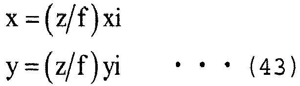
- Namely, coordinates (x,y,z) on the reference object RF that correspond to the point X on the captured image can be obtained. Accordingly, a distance Dr, z (X) from the light source LS to the coordinates (x,y,z) that correspond to the point X of the reference object RF can be calculated according to the following expression 44.

- A method for calculating coefficients A(X), B(X), and C (X) at the point X on the captured image is described next. Luminance values Ir,z1(X), Ir,z2(X), and Ir,z3(X) at the point X of the reference object RF at three different heights z1, z2, and z3 can be calculated according to the following expression 45 on the basis of
expression 42.
- The distances Dr,z1 (X), Dr,z2(X), and Dr,z3(X) in expression 45 can be calculated from
expressions 43 and 44 by applying the height of the reference obj ect RF when the point X on the captured image and the focal distance f are determined. Accordingly, expression 45 includes three simultaneous equations that correspond to three unknown coefficients A(X), B(X), and C(X). Therefore, the coefficients A(X), B(X), and C (X) can be obtained by solving these simultaneous equations. - By storing a set of the coefficients A(X), B(X), and C(X) obtained as described above in the data area of the
storage 30 in association with the point X (pixel X), thereflectance estimating unit 41B can obtain (calculate) the luminance value Ir, z (X) at the point X (pixel X) of the reference object RF at the same height as the height z of the subject ST.FIG. 10 illustrates an example of information in which a set of coefficients (A(X), B(X), and C(X)) is associated with each of the pixels stored in thestorage 30 according toEmbodiment 1. - Return now to
FIG. 9 . Thecoefficient setting unit 41C sets a coefficient α that is used to perform a process of correcting a luminance value and to measure a three-dimensional shape of the subject ST by using the SFS technique according to various conditions such as the height z of the subject ST, the size of a sensor, and the like. InEmbodiment 1, thecoefficient setting unit 41C sets the coefficient α according to the height z of the subject ST. - More specifically, the
coefficient setting unit 41C specifies a coefficient α that corresponds to the height z of the subject ST measured by thedistance measuring unit 41A on the basis of the information that has been stored in thecoefficient storage 31 and that indicates the relationship between the height zr and the coefficient α(zr), and sets the specified coefficient α. When the information that has been stored in thecoefficient storage 31 and that indicates the relationship between the height zr and the coefficient α(zr) is a table as illustrated inFIG. 7 , and a coefficient α(zr) that coincides with the height z of the subject ST has not been registered in the table, thecoefficient setting unit 41C estimates the coefficient α of the height z of the subject ST, for example, with linear interpolation, and sets the estimated coefficient α. - The luminance
value correcting unit 41D further corrects the luminance value Is' (X) input by thereflectance estimating unit 41B, by using the luminance value Ir, z (X) of the reference obj ect RF, in order to reduce influence of peripheral darkening. - More specifically, the luminance
value correcting unit 41D obtains (calculates) the luminance value Ir,z(X) at the point X of the reference object RF at the height z of the subject ST in the method above. Then, the luminancevalue correcting unit 41D calculates a correction coefficient δ(X) for each of the points X on the captured image in accordance with the following expression 46. In expression 46, P is a constant, and the coefficient α is the coefficient α set by thecoefficient setting unit 41C.
- Then, the luminance
value correcting unit 41D further corrects the luminance value Is'(X) in accordance with the following expression 47, and outputs the corrected Is"(X) to the three-dimensionalshape measuring unit 41E.
- When a coefficient k(X) is assumed to be defined by the following expression 48, the coefficient k(X) represents peripheral darkening in a cases in which the luminance value Ir, z(X) at the point X of the reference object RF is proportional to (1/Dr,z(X)α). Accordingly, influence of peripheral darkening can be cancelled by employing the reciprocal of peripheral darkening for the correction coefficient δ(X). As described above, an accuracy in measuring the three-dimensional shape of the subject ST can be improved by removing a factor that is not considered in the conventional SFS technique, such as peripheral darkening.

- The three-dimensional
shape measuring unit 41E calculates a differential equation of the distance-dependent variable model above by using the luminance value Is"(X) input by the luminancevalue correcting unit 41D and the coefficient α set by thecoefficient setting unit 41C so as to measure the three-dimensional shape of the subject ST (a distance from the light source LS to a position of a three-dimensional coordinate system that corresponds to the point X on the captured image) . - The
posture correcting unit 41F corrects a posture of the subject ST in the captured image on the basis of the three-dimensional shape of the subject ST measured by the three-dimensionalshape measuring unit 41E. More specifically, theposture correction unit 41F calculates an angle of a tilt of the subject ST to a reference plane on the basis of the three-dimensional shape of the subject ST measured by the three-dimensionalshape measuring unit 41E. The reference plane is a plane parallel to a horizontal line drawn with a broken line inFIG. 1 , as an example. - The angle of the tile of the subject ST to the reference plane can be obtained, for example, by projecting the three-dimensional shape of the subject ST measured by the three-dimensional
shape measuring unit 41E to two dimensions and performing linear approximation on a two-dimensional projection. In this case, a tilt of the subject ST to an XZ plane by projecting the three-dimensional shape of the subject ST onto the XZ plane and performing linear approximation on a projection on the XZ plane. Similarly, a tilt of the subject ST to a YZ plane by projecting the three-dimensional shape of the subject ST onto the YZ plane and performing linear approximation on a projection on the YZ plane. An angle of a tilt of the subject ST to the reference plane can be obtained by obtaining the tilts of the subject ST to the XZ plane and the YZ plane. The angle of the tilt of the subject ST to the reference plane may be obtained by directly applying a plane equation to the three-dimensional shape of the subject ST. - The
posture correcting unit 41F corrects the posture of the subject ST in the captured image in such a way that the angle of the tilt of the subject ST to the reference plane is "0", namely in such a way that the subject ST is parallel to the reference plane. Theposture correcting unit 41F then outputs the corrected captured image to thefeature extracting unit 42. - With reference to
FIG. 11 , a flow of an authentication process according toEmbodiment 1 is described next.FIG. 11 is an exemplary flowchart explaining the flow of the authentication process according toEmbodiment 1. - The
controller 40 controls theimaging unit 10 to image the subject ST with the subject ST illustrated so as to obtain a capture image, and stores the obtained captured image in the data area of the storage 30 (step S001) . The three-dimensional shapemeasurement processing unit 41 performs a three-dimensional shape measuring process so as to measure a three-dimensional shape of the subject ST, and corrects a posture of the subject ST in the captured image (step S002). - The
feature extracting unit 42 extracts feature data from the captured image in which the posture of the subject ST has been corrected (step S003). Thecollation processing unit 43 collates the feature data extracted in step S003 with feature data for registration that is stored in thedatabase 32, and stores a collation result in the data area of the storage 30 (step S004). Then, the process is finished. - With reference to
FIG. 12 , a flow of a three-dimensional shape measuring process according toEmbodiment 1 is described next.FIG. 12 is an exemplary flowchart explaining the flow of the three-dimensional shape measuring process according toEmbodiment 1. The three-dimensional shape measuring process is a process that corresponds to the process of step S002 in the authentication process. - The
distance measuring unit 41A controls thedistance sensor 20 to detect the height z of the subject ST (step S101). Thereflectance estimating unit 41B estimates a reflectance Rf of the subject ST according toexpression 40 described above, and performs correction to cancel the reflectance Rf peculiar to the subject ST from the luminance value Is(X) at the point X of the captured image according toexpression 41 described above (step S102). - The
coefficient setting unit 41C sets a coefficient α that corresponds to the height z of the subject ST (step S103). The luminancevalue correcting unit 41D performs a luminance value correcting process so as to perform correction to cancel influence of peripheral darkening (step S104). - The three-dimensional
shape measuring unit 41E calculates a differential equation of the distance-dependent variable model by using the luminance value Is"(X) after correction performed by the luminancevalue correcting unit 41D and the coefficient α so as to measure the three-dimensional shape of the subject ST (step S105). Theposture correcting unit 41F corrects the posture of the subject ST in the captured image in such a way that the posture of the subject ST is parallel to the reference plane, on the basis of the three-dimensional shape of the subject ST (step S106). Then, this process is finished, and the process moves on to the process of step S003 in the authentication process. - With reference to
FIG. 13 , a flow of a luminance value correcting process according toEmbodiment 1 is described next.FIG. 13 is an exemplary flowchart explaining the flow of the luminance value correcting process according toEmbodiment 1. The luminance value correcting process is a process that corresponds to the process of step S104 in the three-dimensional shape measuring process. The number of pixels of a captured image is assumed to be (2Mx + 1) x (2My + 1). - The luminance
value correcting unit 41D initiates a coordinate value xi of a pixel X (step S201), and also initiates a coordinate value yi of the pixel X (step S202). Namely, the luminancevalue correcting unit 41D performs initiation so as to be xi = -Mx, and yi = -My. - The luminance
value correcting unit 41D calculates a correction coefficient δ(X) of the pixel X according to expression 46 (step S203), and corrects the luminance value Is'(X) of the pixel X (step S204). - The luminance
value correcting unit 41D increments the coordinate value yi of the pixel X (step S205), and determines whether the incremented coordinate value yi is greater than My (step S206). When the luminancevalue correcting unit 41D determines that the incremented coordinate value yi is less than or equal to My (step S206: NO), the process returns to the process of step S203, and the processes described above are repeated. - When the luminance
value correcting unit 41D determines that the incremented coordinate value yi is greater than My (step S206: YES), the luminancevalue correcting unit 41D increments the coordinate value xi of the pixel X (step S207). The luminancevalue correcting unit 41D then determines whether the incremented coordinate value xi is greater than Mx (step S208). - When the luminance
value correcting unit 41D determines that the incremented coordinate value xi is less than or equal to Mx (step S208: NO), the process returns to the process of step S202, and the processes described above are repeated. When the luminancevalue correcting unit 41D determines that the incremented coordinate value xi is greater than Mx (step S208: YES), this process is finished, and the process moves on to the process of step S105 in the three-dimensional shape measuring process. - According to
Embodiment 1, thebiometric authentication device 100 sets the coefficient α according to the height z of the subject ST. By doing this, an accuracy in measuring the three-dimensional shape of the subject ST measured by using the SFS technique can be improved, even when a relationship between a luminance value and a distance deviates from an ideal point light source model in which the luminance value is inversely proportional to the square of the distance, due to the height z of the subject ST. - In addition, according to
Embodiment 1, thebiometric authentication device 100 estimates the reflectance Rf of the subject ST on the basis of the luminance value of the reference object RF and the luminance value of the captured image, and corrects the luminance value of the captured image in such a way that the reflectance of the subject ST is almost equal to the reflectance of the reference object RF. By doing this, the subject ST can be regarded as an object having the same reflectance as that of the reference object RF, and therefore the three-dimensional shape of the subject ST can be stably measured by using the SFS technique, regardless of the type of the subject ST. - Further, according to
Embodiment 1, thebiometric authentication device 100 performs, on the luminance value of the captured image, correction to remove influence of peripheral darkening on the luminance value of the captured image. An accuracy in measuring the three-dimensional shape of the subject ST can be improved by removing a factor that is not considered in the conventional SFS technique, such as peripheral darkening. - Furthermore, according to
Embodiment 1, thebiometric authentication device 100 corrects a tilt of the subject ST in a captured image on the basis of a measured three-dimensional shape of the subject ST. By doing this, a posture of the subject ST in the captured image can be corrected to the same posture as the posture in a captured image from which feature data for registration has been extracted, and therefore an authentication accuracy can be improved. - In
Embodiment 1, a scheme for setting the coefficient α according the height z of the subject ST has been described. InEmbodiment 2, a case is assumed in which a guiding member that guides a position of the subject ST is provided in abiometric authentication device 100. When the guiding member is provided in thebiometric authentication device 100, the height z of the subject ST is fixed, but a position of the subject ST in the xy direction varies within a prescribed range, and is not fixed. Accordingly, inEmbodiment 2, a scheme for setting the coefficient α according to the position of the subject ST in the xy direction in a case in which the height z of the subject ST is fixed is described. The coefficient α is set according to the position of the subject ST in the xy direction as described above because, in a case in which thebiometric authentication device 100 includes a plurality of light sources LS, the number of light sources LS that illuminate the subject ST may vary depending on the position of the subject ST in the xy direction. -
FIGS. 14A and 14B are diagrams explaining a relationship between a position of the subject ST on a horizontal plane (the position of the subject ST in the xy direction) and a coefficient α according toEmbodiment 2. In the example illustrated inFIG. 14A , illumination light IL that illuminates the subject ST having a height z can be approximated to illumination light IL from one light source LS. Namely, α ≈ 2 is estimated. - In the example illustrated in
FIG. 14B , the subject ST is located in a portion in which rays of illumination light IL are overlapping each other, and therefore illumination light IL that illuminates the subject ST can be approximated to rays of illumination light IL from two light sources LS. Namely, α < 2 is established. -
FIG. 15 is a functional block diagram illustrating an exemplary configuration of abiometric authentication device 100 according toEmbodiment 2.FIG. 16 is a functional block diagram illustrating an exemplary configuration of a three-dimensional shapemeasurement processing unit 41 according toEmbodiment 2. A basic configuration of thebiometric authentication device 100 according toEmbodiment 2 is the same as the configuration according toEmbodiment 1. However, the configuration according toEmbodiment 2 is different from that according toEmbodiment 1 in that thedistance sensor 20 is not included, as illustrated inFIG. 15 . The configuration according toEmbodiment 2 is also different from that according toEmbodiment 1 in that the three-dimensional shapemeasurement processing unit 41 does not include thedistance measuring unit 41A, as illustrated inFIG. 16 . In addition, there are slight differences between the configuration according toEmbodiment 2 and the configuration according toEmbodiment 1 in functions of thecoefficient storage 31 and thecoefficient setting unit 41C. Information relating to the height z of the subject ST fixed by the guiding member is assumed to be stored in the data area of thestorage 30. - The
coefficient storage 31 stores a function Fα(X) for calculating a coefficient α that corresponds to a point X (pixel X) in a captured image. Stated another way, the function Fα(X) is a function for calculating a coefficient α that corresponds to each of the points X on the subject ST included in the captured image. Thecoefficient storage 31 may store information in which the coefficient α is associated with each of the pixels, as illustrated inFIG. 17 , instead of the function Fα(X).FIG. 17 illustrates an example of information that is stored in thecoefficient storage 31 according toEmbodiment 2 and in which the coefficient α is associated with each of the pixels. - The
coefficient setting unit 41C sets the coefficient α according to a position of the subject ST in the xy direction inEmbodiment 2. Namely, thecoefficient setting unit 41C sets the coefficient α according to a position of the subject ST in a captured image. More specifically, thecoefficient setting unit 41C specifies a region T in which the subject ST is located in the captured image in a well-known method, and calculates a mean value αAVE of the coefficient α that corresponds to each of the pixels in the region T according to the following expression 49. In expression 49, NT is the number of pixels in the region T in which the subject ST is located. Expression 49 is an example in a case in which thecoefficient storage 31 stores the function Fα(X).
- The
coefficient setting unit 41C sets the calculated mean value αAVE to be the coefficient α used to perform the luminance value correcting process and to measure the three-dimensional shape of the subject ST by using the SFS technique. - By calculating the mean value αAVE of the coefficient α in the region T in which the subject ST is located and measuring the three-dimensional shape of the subject ST on the basis of the calculated mean value αAVE, as described above, an accuracy in measuring the three-dimensional shape of the subject ST can be improved. This is because a single coefficient α needs to be used to measure the three-dimensional shape of the subject ST by using the SFS technique, although an optimum coefficient α differs for each of the points X on the captured image.
- According to
Embodiment 2, thebiometric authentication device 100 sets the coefficient α on the basis of the position of the subject ST in the xy direction. By doing this, even when a relationship between a luminance value and a distance deviates from an ideal point light source model in which the luminance value is inversely proportional to the square of the distance due to a positional deviation of the subject ST in the xy direction, an accuracy in measuring the three-dimensional shape of the subject ST by using the SFS technique can be improved. - In
Embodiment 1, a scheme for setting the coefficient α in accordance with the height z of the subj ect ST has been described. InEmbodiment 2, a scheme for setting the coefficient α in accordance with the position of the subject ST in the xy direction in a case in which the height z of the subject ST is fixed has been described. - In Embodiment 3, a scheme for setting the coefficient α in accordance with the height z of the subject ST and the position in the xy direction is described.
- A basic configuration of a
biometric authentication device 100 according to Embodiment 3 is the same as the configuration inEmbodiment 1. However, there are slight differences between the configuration according to Embodiment 3 and the configuration according toEmbodiment 1 in functions of acoefficient storage 31 and acoefficient setting unit 41C. - A
coefficient storage 31 stores a function Fα(X,z) for calculating a coefficient α that corresponds to a set of a height z of a subject ST and a point X (pixel X) on a captured image. - In Embodiment 3, a
coefficient setting unit 41C sets the coefficient α in accordance with the height z and the position in the xy direction of the subject ST. More specifically, thecoefficient setting unit 41C specifies a region T in which the subject ST is located in the captured image in a well-known method, and calculates a mean value αAVE of the coefficient α that corresponds to each of the pixels in the region T according to the followingexpression 50. In this case, a height z measured by adistance measuring unit 41C is used for the height z of the subject ST.
- The
coefficient setting unit 41C sets the calculated mean value αAVE to be a coefficient α used to perform a luminance value correcting process and to measure a three-dimensional shape of the subject ST by using the SFS technique. - According to Embodiment 3, the
biometric authentication device 100 sets the coefficient α on the basis of the height z and the position in the xy direction of the subject ST. By doing this, even when a guiding member that guides the position of the subject ST is not provided in thebiometric authentication device 100, the coefficient α can be set in consideration of both the height z and the position in the xy direction of the subject ST. - In
Embodiments 1 to 3, thebiometric authentication device 100 itself includes thedatabase 32, and has a function of collating feature data for collation with feature data for registration that has been registered in thedatabase 32. In Embodiment 4, abiometric authentication system 1 that is configured of one or morebiometric authentication sensors 70 and aserver computer 80 is described as an example. All ofEmbodiments 1 to 3 can be applied to thebiometric authentication system 1, but a case in whichEmbodiment 1 is applied to thebiometric authentication system 1 is now described. -
FIG. 18 illustrates an exemplary configuration of thebiometric authentication system 1 according to Embodiment 4.FIG. 19A is a functional block diagram illustrating an exemplary configuration of thebiometric authentication sensor 70 in thebiometric authentication system 1 according to Embodiment 4, andFIG. 19B is a functional block diagram illustrating an exemplary configuration of theserver computer 80. - In the
biometric authentication system 1 according to Embodiment 4, the one or morebiometric authentication sensors 70 are communicably connected to theserver computer 80 via a network NW, as illustrated inFIG. 18 . - The
biometric authentication sensor 70 according to Embodiment 4 includes animaging unit 10, adistance sensor 20, astorage 30, acontroller 40, and acommunication unit 50, as illustrated inFIG. 19A . Abasic configuration of thebiometric authentication sensor 70 according to Embodiment 4 is the same as the configuration of thebiometric authentication device 100 according toEmbodiment 1. However, as illustrated inFIG. 19A , thebiometric authentication sensor 70 according to Embodiment 4 is different from thebiometric authentication device 100 according toEmbodiment 1 in that thestorage 30 of thebiometric authentication sensor 70 does not function as thedatabase 32 and that thecontroller 40 does not function as thecollation processing unit 43. This is because a collation process is performed on the side of theserver computer 80 in Embodiment 4. In addition, as illustrated inFIG. 19A , thebiometric authentication sensor 70 according to Embodiment 4 is different from thebiometric authentication device 100 according toEmbodiment 1 in that thecommunication unit 50 is included. - The
communication unit 50 includes, for example, a communication module and the like, and performs communication with theserver computer 80. As an example, thecommunication unit 50 transmits feature data extracted by afeature extracting unit 42 to theserver computer 80. As another example, thecommunication unit 50 receives a collation result transmitted from theserver computer 80. The received collation result is stored in the data area of thestorage 30 under the control of thecontroller 40. - The
server computer 80 according to Embodiment 4 includes acommunication unit 81, astorage 82, and acontroller 83, as illustrated inFIG. 19B . - The
communication unit 81 includes, for example, a communication module and the like, and performs communication with each of thebiometric authentication sensors 70 in thebiometric authentication system 1. As an example, thecommunication unit 81 receives feature data transmitted from thebiometric authentication sensor 70. As another example, thecommunication unit 81 transmits a collation result of acollation processing unit 83A to thebiometric authentication sensor 70 that is a transmitter of the feature data. - The
storage 82 includes, for example, a RAM, a ROM, a Hard Disk Drive (HDD), and the like. Thestorage 82 functions as a work area of, for example, a CPU included in thecontroller 83 , a program area in which various programs such as an operation program for controlling the entirety of theserver computer 80 are stored, and a data area in which various types of data are stored. Thestorage 82 also functions as adatabase 82A, as illustrated inFIG. 19B . - The
controller 83 includes, for example, a CPU and the like, and executes the operation program stored in the program area of thestorage 82 so as to realize a function of thecollation processing unit 83A, as illustrated inFIG. 19B . In addition, thecontroller 40 executes the operation program so as to perform processes such as a control program for controlling the entirety of theserver computer 80. -
FIG. 20 illustrates an example of a hardware configuration of the biometric authentication device 100 (or the biometric authentication sensor 70) according to the embodiments. Thebiometric authentication device 100 illustrated inFIG. 6 (or thebiometric authentication sensor 70 illustrated inFIG. 19A ) may be realized by various types of hardware illustrated inFIG. 20 , for example. In the example ofFIG. 20 , the biometric authentication device 100 (or the biometric authentication sensor 70) includes aCPU 201, aRAM 202, aROM 203, aflash memory 204, acamera interface 205 that connects an imaging device, anequipment interface 206 that connects thedistance sensor 20 or the like, acommunication module 207, and areading device 208, and these pieces of hardware are connected to each other via a bus 209. - The
CPU 201 loads an operation program stored, for example, in theflash memory 204 onto theRAM 202, and performs various processes while using theRAM 202 as a working memory. TheCPU 201 can realize respective function units of thecontroller 40 illustrated inFIG. 6 and the like by executing the operation program. - The processes above may be performed by storing an operation program for performing the operations above in a computer-
readable recording medium 210 such as a flexible disk, a Compact Disk-Read Only Memory (CD-ROM), a Digital Versatile Disk (DVD), or a Magneto Optical disk (MO) and distributing the operation program, and reading the operation program by thereading device 208 of the biometric authentication device 100 (or the biometric authentication sensor 70) and installing the operation program onto a computer. Further, an operation program may be stored in a disk drive or the like included in a server computer on the internet, and the operation program may be downloaded to a computer of the biometric authentication device 100 (or the biometric authentication sensor 70). - Depending on embodiments, a storage other than the
RAM 202, theROM 203, and theflash memory 204 may be used. As an example, the biometric authentication device 100 (or the biometric authentication sensor 70) may include a storage such as a Content Addressable Memory (CAM), a Static Random Access Memory (SRAM), or a Synchronous Dynamic Random Access Memory (SDRAM) . - Depending on embodiments, a hardware configuration of the biometric authentication device 100 (or the biometric authentication sensor 70) may be different from the configuration illustrated in
FIG. 20 , and hardware having a standard or type other than that illustrated inFIG. 20 can be employed for the biometric authentication device 100 (or the biometric authentication sensor 70). - As an example, respective function units of the
controller 40 of the biometric authentication device 100 (or the biometric authentication sensor 70) illustrated inFIG. 6 or the like may be realized by a hardware circuit. Specifically, the respective function units of thecontroller 40 illustrated inFIG. 6 or the like may be realized by a reconfigurable circuit such as a Field Programmable Gate Array (FPGA), an Application Specific Integrated Circuit (ASIC), or the like, instead of theCPU 201. Of course, these function units may be realized by both theCPU 201 and the hardware circuit. - Some embodiments and the variations thereof have been described above. However, the embodiments are not limited to the embodiments above, and are to be interpreted as including various variations and alternations of the embodiments above. As an example, it can be understood that various embodiments can be realized by deforming components without departing from the sprit or scope of the embodiments. It can also be understood that various embodiments can be implemented by appropriately combining a plurality of components disclosed in the embodiments above. Further, those skilled in the art could understand that various embodiments can be implemented by deleting or substituting some components of all of the components disclosed in the embodiment, or adding some components to the components disclosed in the embodiment.
Claims (11)
- A three-dimensional shape measuring device that measures a three-dimensional shape of a subject included in a captured image, the three-dimensional shape measuring device comprising:setting means for setting a coefficient that is an index of a power in a model expression for making a luminance value of the captured image be proportional to an inverse of the power of a distance from a light source to a measurement point of the luminance value according to a prescribed condition; andmeasuring means for measuring the three-dimensional shape of the subject according to the luminance value of the captured image and the coefficient.
- The three-dimensional shape measuring device according to claim 1, wherein
the setting means sets the coefficient according to a position of the subject. - The three-dimensional shape measuring device according to claim 2, wherein
the setting means sets the coefficient according to a height of the subject from the light source. - The three-dimensional shape measuring device according to claim 2, wherein
the setting means sets the coefficient according to a position of the subject in the captured image. - The three-dimensional shape measuring device according to claim 4, wherein
the setting means specifies a region of the subject in the captured image, and sets a mean value of the index that corresponds to each pixel included in the region to be the coefficient. - The three-dimensional shape measuring device according to any one of claims 1 to 5, further comprising:first correcting means for estimating a reflectance of the subject according to the luminance value of a reference object that is a plane body for which a stored reflectance is constant and known, and the luminance value of the subject in the captured image, and performing, on the luminance value of the captured image, correction to make the reflectance of the subject almost equal to the reflectance of the reference object according to the estimated reflectance, whereinthe measuring means measures the three-dimensional shape of the subject according to the corrected luminance value of the captured image and the coefficient.
- The three-dimensional shape measuring device according to any one of claims 1 to 5, further comprising:second correcting means for performing, on the luminance value of the captured image, correction to remove influence of peripheral darkening on the luminance value of the captured image, whereinthe measuring means measuring the three-dimensional shape of the subject according to the corrected luminance value of the captured image and the coefficient.
- The three-dimensional shape measuring device according to claim 7, wherein
the second correcting means performs the correction to remove the influence of the peripheral darkening under the assumption that the index of the power of the distance from the light source to which the peripheral darkening is almost proportional is the coefficient. - The three-dimensional shape measuring device according to any one of claims 1 to 8, further comprising:the correcting means for correcting a tilt of the subject in the captured image according to the three-dimensional shape of the subject.
- A three-dimensional shape measuring method for measuring a three-dimensional shape of a subject included in a captured image, the three-dimensional shape measuring method comprising:setting a coefficient that is an index of a power in a model expression for making a luminance value of the captured image be proportional to an inverse of the power of a distance from a light source to a measurement point of the luminance value according to a prescribed condition; andmeasuring the three-dimensional shape of the subject according to the luminance value of the captured image and the coefficient.
- A program for causing a computer of a three-dimensional shape measuring device that measures a three-dimensional shape of a subject included in a captured image to execute a process comprising:setting a coefficient that is an index of a power in a model expression for making a luminance value of the captured image be proportional to an inverse of the power of a distance from a light source to a measurement point of the luminance value according to a prescribed condition; andmeasuring the three-dimensional shape of the subject according to the luminance value of the captured image and the coefficient.
Applications Claiming Priority (1)
| Application Number | Priority Date | Filing Date | Title |
|---|---|---|---|
| JP2015002698A JP6531395B2 (en) | 2015-01-08 | 2015-01-08 | Three-dimensional shape measuring device, three-dimensional shape measuring method, and program |
Publications (2)
| Publication Number | Publication Date |
|---|---|
| EP3042609A1 true EP3042609A1 (en) | 2016-07-13 |
| EP3042609B1 EP3042609B1 (en) | 2019-09-04 |
Family
ID=55024749
Family Applications (1)
| Application Number | Title | Priority Date | Filing Date |
|---|---|---|---|
| EP15199246.8A Active EP3042609B1 (en) | 2015-01-08 | 2015-12-10 | Three-dimensional shape measuring device, three-dimensional shape measuring method, and program |
Country Status (5)
| Country | Link |
|---|---|
| US (1) | US10145679B2 (en) |
| EP (1) | EP3042609B1 (en) |
| JP (1) | JP6531395B2 (en) |
| KR (1) | KR101808925B1 (en) |
| CN (1) | CN105783768B (en) |
Families Citing this family (4)
| Publication number | Priority date | Publication date | Assignee | Title |
|---|---|---|---|---|
| DE102018004592A1 (en) * | 2017-06-20 | 2018-12-20 | Mitutoyo Corporation | Measuring apparatus for three-dimensional geometry and measuring method for three-dimensional geometry |
| CN111722187B (en) * | 2019-03-19 | 2024-02-23 | 富士通株式会社 | Radar installation parameter calculation method and device |
| US20210279492A1 (en) * | 2020-02-28 | 2021-09-09 | The Government of the United States of America, as represented by the Secretary of Homeland Security | Skin reflectance image correction in biometric image capture |
| GB2614251A (en) * | 2021-12-22 | 2023-07-05 | Hidef Aerial Surveying Ltd | Classification, length measurement and height measurement apparatus and method |
Citations (1)
| Publication number | Priority date | Publication date | Assignee | Title |
|---|---|---|---|---|
| JP2007010346A (en) | 2005-06-28 | 2007-01-18 | Fujitsu Ltd | Imaging device |
Family Cites Families (9)
| Publication number | Priority date | Publication date | Assignee | Title |
|---|---|---|---|---|
| DE10346481B4 (en) * | 2003-10-02 | 2013-01-17 | Daimler Ag | Three-dimensional reconstruction of surface profiles |
| EP2261852B1 (en) * | 2008-03-06 | 2013-10-16 | Fujitsu Limited | Image photographic device, image photographic method, and image photographic program |
| JP5393215B2 (en) | 2009-03-24 | 2014-01-22 | オリンパス株式会社 | Fluorescence observation apparatus, fluorescence observation system, and operation method of fluorescence observation apparatus |
| WO2011030441A1 (en) * | 2009-09-11 | 2011-03-17 | 富士通株式会社 | Biometric authentication device, biometric authentication system, and biometric authentication method |
| JP2013196331A (en) | 2012-03-19 | 2013-09-30 | Denso Corp | Imaging control device and program |
| EP2833320B1 (en) * | 2012-03-28 | 2018-04-18 | Fujitsu Limited | Biometric authentication device, biometric authentication method, and biometric authentication program |
| WO2013145168A1 (en) * | 2012-03-28 | 2013-10-03 | 富士通株式会社 | Biometric authentication device, biometric authentication method, and biometric authentication program |
| CN104246824B (en) * | 2012-03-30 | 2017-05-10 | 富士通株式会社 | Biometric authentication device and biometric authentication method |
| JP6089872B2 (en) * | 2013-03-28 | 2017-03-08 | 富士通株式会社 | Image correction apparatus, image correction method, and biometric authentication apparatus |
-
2015
- 2015-01-08 JP JP2015002698A patent/JP6531395B2/en active Active
- 2015-12-10 EP EP15199246.8A patent/EP3042609B1/en active Active
- 2015-12-11 US US14/966,960 patent/US10145679B2/en active Active
- 2015-12-17 KR KR1020150181112A patent/KR101808925B1/en active Active
- 2015-12-18 CN CN201510958072.1A patent/CN105783768B/en active Active
Patent Citations (1)
| Publication number | Priority date | Publication date | Assignee | Title |
|---|---|---|---|---|
| JP2007010346A (en) | 2005-06-28 | 2007-01-18 | Fujitsu Ltd | Imaging device |
Non-Patent Citations (6)
| Title |
|---|
| E. PRADOS ET AL.: "Shape from Shading: a well-posed problem?", INRIA, August 2004 (2004-08-01), pages 1 - 55 |
| PRADOS E ET AL: "Shape from Shading: A Well-Posed Problem?", PROCEEDINGS / 2005 IEEE COMPUTER SOCIETY CONFERENCE ON COMPUTER VISION AND PATTERN RECOGNITION, CVPR 2005 : [20 - 25 JUNE 2005, SAN DIEGO, CA], IEEE, PISCATAWAY, NJ, USA, vol. 2, 20 June 2005 (2005-06-20), pages 870 - 877, XP010817545, ISBN: 978-0-7695-2372-9, DOI: 10.1109/CVPR.2005.319 * |
| QUARTUCCI FORSTER C H ET AL: "Towards 3D reconstruction of endoscope images using shape from shading", COMPUTER GRAPHICS AND IMAGE PROCESSING, 2000. PROCEEDINGS XIII BRAZILI AN SYMPOSIUM ON GRAMADO, BRAZIL 17-20 OCT. 2000, LOS ALAMITOS, CA, USA,IEEE COMPUT. SOC, US, 17 October 2000 (2000-10-17), pages 90 - 96, XP010521932, ISBN: 978-0-7695-0878-8, DOI: 10.1109/SIBGRA.2000.883900 * |
| R. KIMMEL ET AL.: "Global Shape from Shading", CVGIP: IMAGE UNDERSTANDING, 1995, pages 120 - 125 |
| R. ZHANG ET AL.: "Shape from Shading: A Survey", IEEE PAMI (TRANSACTIONS ON PATTERN ANALYSIS AND MACHINE INTELLIGENCE, vol. 21, no. 8, August 1999 (1999-08-01), pages 690 - 706 |
| T OKATANI ET AL: "Shape Reconstruction from an Endoscope Image by Shape from Shading Technique for a Point Light Source at the Projection Center", COMPUTER VISION AND IMAGE UNDERSTANDING, vol. 66, no. 2, 1 May 1997 (1997-05-01), pages 119 - 131, XP055155053, ISSN: 1077-3142, DOI: 10.1006/cviu.1997.0613 * |
Also Published As
| Publication number | Publication date |
|---|---|
| JP2016125995A (en) | 2016-07-11 |
| CN105783768A (en) | 2016-07-20 |
| JP6531395B2 (en) | 2019-06-19 |
| US10145679B2 (en) | 2018-12-04 |
| US20160202047A1 (en) | 2016-07-14 |
| CN105783768B (en) | 2018-09-04 |
| EP3042609B1 (en) | 2019-09-04 |
| KR20160085693A (en) | 2016-07-18 |
| KR101808925B1 (en) | 2017-12-13 |
Similar Documents
| Publication | Publication Date | Title |
|---|---|---|
| KR102938692B1 (en) | Associate 3D coordinates with 2D feature points | |
| US11654571B2 (en) | Three-dimensional data generation device and robot control system | |
| JP5671281B2 (en) | Position / orientation measuring apparatus, control method and program for position / orientation measuring apparatus | |
| US20130230235A1 (en) | Information processing apparatus and information processing method | |
| KR20160003776A (en) | Posture estimation method and robot | |
| JP6340838B2 (en) | Biometric authentication device, biometric authentication method, and program | |
| JP6101134B2 (en) | Information processing apparatus and information processing method | |
| US20190313082A1 (en) | Apparatus and method for measuring position of stereo camera | |
| EP3042609B1 (en) | Three-dimensional shape measuring device, three-dimensional shape measuring method, and program | |
| US20140232696A1 (en) | Information processing apparatus and information processing method | |
| JP6282377B2 (en) | Three-dimensional shape measurement system and measurement method thereof | |
| JP5976089B2 (en) | Position / orientation measuring apparatus, position / orientation measuring method, and program | |
| JP2016170050A (en) | Position / orientation measuring apparatus, position / orientation measuring method, and computer program | |
| JP2016148956A (en) | Positioning device, positioning method and positioning computer program | |
| JP2021056017A (en) | Synthetic processing apparatus, synthetic processing system and synthetic processing method | |
| JP6845929B2 (en) | 3D measuring device and method | |
| US10275900B2 (en) | Estimation apparatus, estimation method, and computer program product | |
| US11417144B2 (en) | Processing apparatus, fingerprint image extraction processing apparatus, system, processing method, and computer readable medium | |
| KR102846973B1 (en) | Image processing system and method for moving amount estimation | |
| WO2020230390A1 (en) | Position and attitude estimating device and position and attitude estimating method | |
| JP6890422B2 (en) | Information processing equipment, control methods and programs for information processing equipment | |
| JP2018124177A (en) | Floor judgment method | |
| KR20160052256A (en) | Three-dimensional space Mapping apparatus using a virtual feature point and method therefor | |
| WO2014192061A1 (en) | Image processing device, image processing method, and image processing program | |
| JP2023128662A (en) | measurement system |
Legal Events
| Date | Code | Title | Description |
|---|---|---|---|
| PUAI | Public reference made under article 153(3) epc to a published international application that has entered the european phase |
Free format text: ORIGINAL CODE: 0009012 |
|
| AK | Designated contracting states |
Kind code of ref document: A1 Designated state(s): AL AT BE BG CH CY CZ DE DK EE ES FI FR GB GR HR HU IE IS IT LI LT LU LV MC MK MT NL NO PL PT RO RS SE SI SK SM TR |
|
| AX | Request for extension of the european patent |
Extension state: BA ME |
|
| STAA | Information on the status of an ep patent application or granted ep patent |
Free format text: STATUS: REQUEST FOR EXAMINATION WAS MADE |
|
| 17P | Request for examination filed |
Effective date: 20161214 |
|
| RBV | Designated contracting states (corrected) |
Designated state(s): AL AT BE BG CH CY CZ DE DK EE ES FI FR GB GR HR HU IE IS IT LI LT LU LV MC MK MT NL NO PL PT RO RS SE SI SK SM TR |
|
| STAA | Information on the status of an ep patent application or granted ep patent |
Free format text: STATUS: EXAMINATION IS IN PROGRESS |
|
| 17Q | First examination report despatched |
Effective date: 20181120 |
|
| REG | Reference to a national code |
Ref country code: DE Ref legal event code: R079 Ref document number: 602015037088 Country of ref document: DE Free format text: PREVIOUS MAIN CLASS: A61B0005117000 Ipc: G01B0011240000 |
|
| GRAP | Despatch of communication of intention to grant a patent |
Free format text: ORIGINAL CODE: EPIDOSNIGR1 |
|
| STAA | Information on the status of an ep patent application or granted ep patent |
Free format text: STATUS: GRANT OF PATENT IS INTENDED |
|
| RIC1 | Information provided on ipc code assigned before grant |
Ipc: G06K 9/20 20060101ALI20190315BHEP Ipc: A61B 5/117 20160101ALI20190315BHEP Ipc: G01B 11/24 20060101AFI20190315BHEP Ipc: G06K 9/00 20060101ALI20190315BHEP Ipc: G06T 7/507 20170101ALI20190315BHEP |
|
| INTG | Intention to grant announced |
Effective date: 20190409 |
|
| GRAS | Grant fee paid |
Free format text: ORIGINAL CODE: EPIDOSNIGR3 |
|
| GRAA | (expected) grant |
Free format text: ORIGINAL CODE: 0009210 |
|
| STAA | Information on the status of an ep patent application or granted ep patent |
Free format text: STATUS: THE PATENT HAS BEEN GRANTED |
|
| AK | Designated contracting states |
Kind code of ref document: B1 Designated state(s): AL AT BE BG CH CY CZ DE DK EE ES FI FR GB GR HR HU IE IS IT LI LT LU LV MC MK MT NL NO PL PT RO RS SE SI SK SM TR |
|
| REG | Reference to a national code |
Ref country code: GB Ref legal event code: FG4D |
|
| REG | Reference to a national code |
Ref country code: CH Ref legal event code: EP |
|
| REG | Reference to a national code |
Ref country code: AT Ref legal event code: REF Ref document number: 1175986 Country of ref document: AT Kind code of ref document: T Effective date: 20190915 |
|
| REG | Reference to a national code |
Ref country code: DE Ref legal event code: R096 Ref document number: 602015037088 Country of ref document: DE |
|
| REG | Reference to a national code |
Ref country code: IE Ref legal event code: FG4D |
|
| REG | Reference to a national code |
Ref country code: NL Ref legal event code: MP Effective date: 20190904 |
|
| REG | Reference to a national code |
Ref country code: LT Ref legal event code: MG4D |
|
| PG25 | Lapsed in a contracting state [announced via postgrant information from national office to epo] |
Ref country code: FI Free format text: LAPSE BECAUSE OF FAILURE TO SUBMIT A TRANSLATION OF THE DESCRIPTION OR TO PAY THE FEE WITHIN THE PRESCRIBED TIME-LIMIT Effective date: 20190904 Ref country code: LT Free format text: LAPSE BECAUSE OF FAILURE TO SUBMIT A TRANSLATION OF THE DESCRIPTION OR TO PAY THE FEE WITHIN THE PRESCRIBED TIME-LIMIT Effective date: 20190904 Ref country code: SE Free format text: LAPSE BECAUSE OF FAILURE TO SUBMIT A TRANSLATION OF THE DESCRIPTION OR TO PAY THE FEE WITHIN THE PRESCRIBED TIME-LIMIT Effective date: 20190904 Ref country code: HR Free format text: LAPSE BECAUSE OF FAILURE TO SUBMIT A TRANSLATION OF THE DESCRIPTION OR TO PAY THE FEE WITHIN THE PRESCRIBED TIME-LIMIT Effective date: 20190904 Ref country code: NO Free format text: LAPSE BECAUSE OF FAILURE TO SUBMIT A TRANSLATION OF THE DESCRIPTION OR TO PAY THE FEE WITHIN THE PRESCRIBED TIME-LIMIT Effective date: 20191204 Ref country code: BG Free format text: LAPSE BECAUSE OF FAILURE TO SUBMIT A TRANSLATION OF THE DESCRIPTION OR TO PAY THE FEE WITHIN THE PRESCRIBED TIME-LIMIT Effective date: 20191204 |
|
| PG25 | Lapsed in a contracting state [announced via postgrant information from national office to epo] |
Ref country code: LV Free format text: LAPSE BECAUSE OF FAILURE TO SUBMIT A TRANSLATION OF THE DESCRIPTION OR TO PAY THE FEE WITHIN THE PRESCRIBED TIME-LIMIT Effective date: 20190904 Ref country code: ES Free format text: LAPSE BECAUSE OF FAILURE TO SUBMIT A TRANSLATION OF THE DESCRIPTION OR TO PAY THE FEE WITHIN THE PRESCRIBED TIME-LIMIT Effective date: 20190904 Ref country code: AL Free format text: LAPSE BECAUSE OF FAILURE TO SUBMIT A TRANSLATION OF THE DESCRIPTION OR TO PAY THE FEE WITHIN THE PRESCRIBED TIME-LIMIT Effective date: 20190904 Ref country code: GR Free format text: LAPSE BECAUSE OF FAILURE TO SUBMIT A TRANSLATION OF THE DESCRIPTION OR TO PAY THE FEE WITHIN THE PRESCRIBED TIME-LIMIT Effective date: 20191205 Ref country code: RS Free format text: LAPSE BECAUSE OF FAILURE TO SUBMIT A TRANSLATION OF THE DESCRIPTION OR TO PAY THE FEE WITHIN THE PRESCRIBED TIME-LIMIT Effective date: 20190904 |
|
| REG | Reference to a national code |
Ref country code: AT Ref legal event code: MK05 Ref document number: 1175986 Country of ref document: AT Kind code of ref document: T Effective date: 20190904 |
|
| PG25 | Lapsed in a contracting state [announced via postgrant information from national office to epo] |
Ref country code: NL Free format text: LAPSE BECAUSE OF FAILURE TO SUBMIT A TRANSLATION OF THE DESCRIPTION OR TO PAY THE FEE WITHIN THE PRESCRIBED TIME-LIMIT Effective date: 20190904 Ref country code: PL Free format text: LAPSE BECAUSE OF FAILURE TO SUBMIT A TRANSLATION OF THE DESCRIPTION OR TO PAY THE FEE WITHIN THE PRESCRIBED TIME-LIMIT Effective date: 20190904 Ref country code: AT Free format text: LAPSE BECAUSE OF FAILURE TO SUBMIT A TRANSLATION OF THE DESCRIPTION OR TO PAY THE FEE WITHIN THE PRESCRIBED TIME-LIMIT Effective date: 20190904 Ref country code: EE Free format text: LAPSE BECAUSE OF FAILURE TO SUBMIT A TRANSLATION OF THE DESCRIPTION OR TO PAY THE FEE WITHIN THE PRESCRIBED TIME-LIMIT Effective date: 20190904 Ref country code: RO Free format text: LAPSE BECAUSE OF FAILURE TO SUBMIT A TRANSLATION OF THE DESCRIPTION OR TO PAY THE FEE WITHIN THE PRESCRIBED TIME-LIMIT Effective date: 20190904 Ref country code: PT Free format text: LAPSE BECAUSE OF FAILURE TO SUBMIT A TRANSLATION OF THE DESCRIPTION OR TO PAY THE FEE WITHIN THE PRESCRIBED TIME-LIMIT Effective date: 20200106 Ref country code: IT Free format text: LAPSE BECAUSE OF FAILURE TO SUBMIT A TRANSLATION OF THE DESCRIPTION OR TO PAY THE FEE WITHIN THE PRESCRIBED TIME-LIMIT Effective date: 20190904 |
|
| PG25 | Lapsed in a contracting state [announced via postgrant information from national office to epo] |
Ref country code: SK Free format text: LAPSE BECAUSE OF FAILURE TO SUBMIT A TRANSLATION OF THE DESCRIPTION OR TO PAY THE FEE WITHIN THE PRESCRIBED TIME-LIMIT Effective date: 20190904 Ref country code: IS Free format text: LAPSE BECAUSE OF FAILURE TO SUBMIT A TRANSLATION OF THE DESCRIPTION OR TO PAY THE FEE WITHIN THE PRESCRIBED TIME-LIMIT Effective date: 20200224 Ref country code: SM Free format text: LAPSE BECAUSE OF FAILURE TO SUBMIT A TRANSLATION OF THE DESCRIPTION OR TO PAY THE FEE WITHIN THE PRESCRIBED TIME-LIMIT Effective date: 20190904 Ref country code: CZ Free format text: LAPSE BECAUSE OF FAILURE TO SUBMIT A TRANSLATION OF THE DESCRIPTION OR TO PAY THE FEE WITHIN THE PRESCRIBED TIME-LIMIT Effective date: 20190904 |
|
| REG | Reference to a national code |
Ref country code: DE Ref legal event code: R097 Ref document number: 602015037088 Country of ref document: DE |
|
| PLBE | No opposition filed within time limit |
Free format text: ORIGINAL CODE: 0009261 |
|
| STAA | Information on the status of an ep patent application or granted ep patent |
Free format text: STATUS: NO OPPOSITION FILED WITHIN TIME LIMIT |
|
| PG2D | Information on lapse in contracting state deleted |
Ref country code: IS |
|
| PG25 | Lapsed in a contracting state [announced via postgrant information from national office to epo] |
Ref country code: DK Free format text: LAPSE BECAUSE OF FAILURE TO SUBMIT A TRANSLATION OF THE DESCRIPTION OR TO PAY THE FEE WITHIN THE PRESCRIBED TIME-LIMIT Effective date: 20190904 Ref country code: IS Free format text: LAPSE BECAUSE OF FAILURE TO SUBMIT A TRANSLATION OF THE DESCRIPTION OR TO PAY THE FEE WITHIN THE PRESCRIBED TIME-LIMIT Effective date: 20200105 |
|
| REG | Reference to a national code |
Ref country code: CH Ref legal event code: PL |
|
| 26N | No opposition filed |
Effective date: 20200605 |
|
| REG | Reference to a national code |
Ref country code: BE Ref legal event code: MM Effective date: 20191231 |
|
| PG25 | Lapsed in a contracting state [announced via postgrant information from national office to epo] |
Ref country code: SI Free format text: LAPSE BECAUSE OF FAILURE TO SUBMIT A TRANSLATION OF THE DESCRIPTION OR TO PAY THE FEE WITHIN THE PRESCRIBED TIME-LIMIT Effective date: 20190904 Ref country code: MC Free format text: LAPSE BECAUSE OF FAILURE TO SUBMIT A TRANSLATION OF THE DESCRIPTION OR TO PAY THE FEE WITHIN THE PRESCRIBED TIME-LIMIT Effective date: 20190904 |
|
| PG25 | Lapsed in a contracting state [announced via postgrant information from national office to epo] |
Ref country code: LU Free format text: LAPSE BECAUSE OF NON-PAYMENT OF DUE FEES Effective date: 20191210 Ref country code: IE Free format text: LAPSE BECAUSE OF NON-PAYMENT OF DUE FEES Effective date: 20191210 |
|
| PG25 | Lapsed in a contracting state [announced via postgrant information from national office to epo] |
Ref country code: CH Free format text: LAPSE BECAUSE OF NON-PAYMENT OF DUE FEES Effective date: 20191231 Ref country code: BE Free format text: LAPSE BECAUSE OF NON-PAYMENT OF DUE FEES Effective date: 20191231 Ref country code: LI Free format text: LAPSE BECAUSE OF NON-PAYMENT OF DUE FEES Effective date: 20191231 |
|
| PG25 | Lapsed in a contracting state [announced via postgrant information from national office to epo] |
Ref country code: CY Free format text: LAPSE BECAUSE OF FAILURE TO SUBMIT A TRANSLATION OF THE DESCRIPTION OR TO PAY THE FEE WITHIN THE PRESCRIBED TIME-LIMIT Effective date: 20190904 |
|
| PG25 | Lapsed in a contracting state [announced via postgrant information from national office to epo] |
Ref country code: MT Free format text: LAPSE BECAUSE OF FAILURE TO SUBMIT A TRANSLATION OF THE DESCRIPTION OR TO PAY THE FEE WITHIN THE PRESCRIBED TIME-LIMIT Effective date: 20190904 Ref country code: HU Free format text: LAPSE BECAUSE OF FAILURE TO SUBMIT A TRANSLATION OF THE DESCRIPTION OR TO PAY THE FEE WITHIN THE PRESCRIBED TIME-LIMIT; INVALID AB INITIO Effective date: 20151210 |
|
| PG25 | Lapsed in a contracting state [announced via postgrant information from national office to epo] |
Ref country code: TR Free format text: LAPSE BECAUSE OF FAILURE TO SUBMIT A TRANSLATION OF THE DESCRIPTION OR TO PAY THE FEE WITHIN THE PRESCRIBED TIME-LIMIT Effective date: 20190904 |
|
| PG25 | Lapsed in a contracting state [announced via postgrant information from national office to epo] |
Ref country code: MK Free format text: LAPSE BECAUSE OF FAILURE TO SUBMIT A TRANSLATION OF THE DESCRIPTION OR TO PAY THE FEE WITHIN THE PRESCRIBED TIME-LIMIT Effective date: 20190904 |
|
| PGFP | Annual fee paid to national office [announced via postgrant information from national office to epo] |
Ref country code: DE Payment date: 20251126 Year of fee payment: 11 |
|
| PGFP | Annual fee paid to national office [announced via postgrant information from national office to epo] |
Ref country code: GB Payment date: 20251119 Year of fee payment: 11 |
|
| PGFP | Annual fee paid to national office [announced via postgrant information from national office to epo] |
Ref country code: FR Payment date: 20251120 Year of fee payment: 11 |