EP3041997B1 - Method of demand management and control of fluid pipe networks - Google Patents
Method of demand management and control of fluid pipe networks Download PDFInfo
- Publication number
- EP3041997B1 EP3041997B1 EP14841712.4A EP14841712A EP3041997B1 EP 3041997 B1 EP3041997 B1 EP 3041997B1 EP 14841712 A EP14841712 A EP 14841712A EP 3041997 B1 EP3041997 B1 EP 3041997B1
- Authority
- EP
- European Patent Office
- Prior art keywords
- valves
- fluid
- valve
- network
- pressure head
- Prior art date
- Legal status (The legal status is an assumption and is not a legal conclusion. Google has not performed a legal analysis and makes no representation as to the accuracy of the status listed.)
- Active
Links
Images




Classifications
-
- E—FIXED CONSTRUCTIONS
- E02—HYDRAULIC ENGINEERING; FOUNDATIONS; SOIL SHIFTING
- E02B—HYDRAULIC ENGINEERING
- E02B1/00—Equipment or apparatus for, or methods of, general hydraulic engineering, e.g. protection of constructions against ice-strains
-
- G—PHYSICS
- G05—CONTROLLING; REGULATING
- G05D—SYSTEMS FOR CONTROLLING OR REGULATING NON-ELECTRIC VARIABLES
- G05D7/00—Control of flow
- G05D7/06—Control of flow characterised by the use of electric means
- G05D7/0617—Control of flow characterised by the use of electric means specially adapted for fluid materials
- G05D7/0629—Control of flow characterised by the use of electric means specially adapted for fluid materials characterised by the type of regulator means
- G05D7/0635—Control of flow characterised by the use of electric means specially adapted for fluid materials characterised by the type of regulator means by action on throttling means
- G05D7/0641—Control of flow characterised by the use of electric means specially adapted for fluid materials characterised by the type of regulator means by action on throttling means using a plurality of throttling means
- G05D7/0664—Control of flow characterised by the use of electric means specially adapted for fluid materials characterised by the type of regulator means by action on throttling means using a plurality of throttling means the plurality of throttling means being arranged for the control of a plurality of diverging flows from a single flow
-
- F—MECHANICAL ENGINEERING; LIGHTING; HEATING; WEAPONS; BLASTING
- F17—STORING OR DISTRIBUTING GASES OR LIQUIDS
- F17D—PIPE-LINE SYSTEMS; PIPE-LINES
- F17D1/00—Pipe-line systems
-
- G—PHYSICS
- G05—CONTROLLING; REGULATING
- G05B—CONTROL OR REGULATING SYSTEMS IN GENERAL; FUNCTIONAL ELEMENTS OF SUCH SYSTEMS; MONITORING OR TESTING ARRANGEMENTS FOR SUCH SYSTEMS OR ELEMENTS
- G05B17/00—Systems involving the use of models or simulators of said systems
- G05B17/02—Systems involving the use of models or simulators of said systems electric
-
- G—PHYSICS
- G05—CONTROLLING; REGULATING
- G05B—CONTROL OR REGULATING SYSTEMS IN GENERAL; FUNCTIONAL ELEMENTS OF SUCH SYSTEMS; MONITORING OR TESTING ARRANGEMENTS FOR SUCH SYSTEMS OR ELEMENTS
- G05B19/00—Program-control systems
-
- G—PHYSICS
- G05—CONTROLLING; REGULATING
- G05D—SYSTEMS FOR CONTROLLING OR REGULATING NON-ELECTRIC VARIABLES
- G05D7/00—Control of flow
- G05D7/06—Control of flow characterised by the use of electric means
-
- G—PHYSICS
- G05—CONTROLLING; REGULATING
- G05D—SYSTEMS FOR CONTROLLING OR REGULATING NON-ELECTRIC VARIABLES
- G05D7/00—Control of flow
- G05D7/06—Control of flow characterised by the use of electric means
- G05D7/0617—Control of flow characterised by the use of electric means specially adapted for fluid materials
- G05D7/0629—Control of flow characterised by the use of electric means specially adapted for fluid materials characterised by the type of regulator means
- G05D7/0635—Control of flow characterised by the use of electric means specially adapted for fluid materials characterised by the type of regulator means by action on throttling means
- G05D7/0641—Control of flow characterised by the use of electric means specially adapted for fluid materials characterised by the type of regulator means by action on throttling means using a plurality of throttling means
-
- G—PHYSICS
- G06—COMPUTING OR CALCULATING; COUNTING
- G06F—ELECTRIC DIGITAL DATA PROCESSING
- G06F17/00—Digital computing or data processing equipment or methods, specially adapted for specific functions
-
- G—PHYSICS
- G16—INFORMATION AND COMMUNICATION TECHNOLOGY [ICT] SPECIALLY ADAPTED FOR SPECIFIC APPLICATION FIELDS
- G16Z—INFORMATION AND COMMUNICATION TECHNOLOGY [ICT] SPECIALLY ADAPTED FOR SPECIFIC APPLICATION FIELDS, NOT OTHERWISE PROVIDED FOR
- G16Z99/00—Subject matter not provided for in other main groups of this subclass
-
- E—FIXED CONSTRUCTIONS
- E02—HYDRAULIC ENGINEERING; FOUNDATIONS; SOIL SHIFTING
- E02B—HYDRAULIC ENGINEERING
- E02B13/00—Irrigation ditches, i.e. gravity flow, open channel water distribution systems
Definitions
- the present invention relates to a method of demand management and control for limited pressure head or gravity fed fluid closed conduit networks, and relates particularly, though not exclusively, to a method of demand management and control for limited pressure head or gravity fed water irrigation pipe networks.
- the method is applicable to both a closed conduits (pipeline network) and open conduits (channel networks).
- Gravity pipe networks typically operate within limited pressure head and therefore are constrained in their capability to meet demand.
- Known models for pipe networks would be used in the management of demand for these networks.
- Data from the SCADA system would be used to calibrate and continually fine-tune the model of the pipe conveyance network based on system identification techniques.
- Flow measurement and pressure head measurements would be located at points on the pipe network that would be deemed necessary to calibrate the model to the desired accuracy.
- the supply points to users are the primary form of control used with a pipe network.
- the controller for a pipe network is much simpler than it is for a channel network with the principle form of control being maintaining the flow at the supply point equal to that of the order.
- Control and management of demand is especially applicable to gravity pipe networks commonly used for the supply of irrigation water. Difficulties have arisen to implement such systems as gravity pipe networks typically operate within limited pressure head and therefore are constrained in their capability to continually meet demand. Gravity pipelines also typically operate at lower pressure heads where there will be greater interaction between flows at outlets due to valve operations. Accordingly, assuming all the parameters such as pipe diameter, flow rate, valve size, etc. being the same, the higher the static pressure head (e.g. from pumping), the less sensitive the impact of flow fluctuations due to valve operations (e.g. valves opening or closing) on other valves in operation.
- Fig. 1 illustrates why operating valves are less sensitive to flow variations in the supply pipeline (e.g. from other opening and closing valves) with a higher pressure head in the pipeline.
- Fig. 1 shows a graph of the hydraulic grade line or pressure head against the valve position for a high pressure at line 10 and for a low pressure or gravity fed hydraulic grade line or pressure head at line 12.
- Gravity fed pipe 14 is shown on a grade with two valves 16 and 18. Although pipe 14 is shown on a grade, it could be horizontal if the water supply is elevated to provide the required pressure head. For line 10, pipe 14 would be coupled to a pump (not shown) to produce a high-pressure head.
- valves can be manually positioned to a set opening to achieve a certain flow, and the flow will not be impacted significantly by the operation of the other valves (e.g. valves opening or closing) in the pipeline.
- low-pressure pipelines require an integrated control and demand management system to manage the valve interaction within the tight hydraulic grade line conditions.
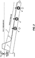
- Fig. 2 shows pipeline 14 separated from Fig. 1 and illustrates the maximum supply pressure 22 which must maintain the pipeline full to ensure the accuracy of the flow meters (not shown) associated with valves 16, 18, and 20. It is important to keep the pipeline full to make the control problem simple and tractable as a "pipe not full” scenario will significantly change the physics that governs the dynamics of pipe flow. Pipe flow transitioning between "pipe full” and “pipe not full” states will make achieving robust control intractable. Maintaining the hydraulic grade line 12 associated with the pipeline 14 above the maximum supply pressure 22 will also ensure that the pressure head at the valves 16, 18 and 20 are high enough to guarantee the flow rate the valves were designed for.
- the low-pressure head or hydraulic grade line 12 associated with pipeline 14 will potentially result in increased controller interaction between the discrete control actions necessary to maintain desired flows at the valves. This is further compounded with gravity pipelines where the flow capacity at the valves is high in relation to the overall flow capacity of the main trunk pipeline. The action of opening or closing valves will impact the pressure head, and therefore flow, at all other valves on the pipeline 14 that are operating. Therefore there will be interaction between various automated valves operating off the pipeline. In this low energy pipeline, the control will be subject to instability. Each movement in a valve has a level of interaction with all the other operating valves plus supply level variation at the source or at the outlet (on-farm). Because of the low pressure in the pipeline 14, the hydraulic grade line 12 is very sensitive to the operation of the valve/outlets.
- FIG. 3 This sensitivity is illustrated in Fig. 3 where a graph of flow and time is shown.
- Line 24 illustrates valve 16 being already open and the effect that the opening of valve 18 has on the network.
- Line 26 illustrates the flow of valve 18.
- Both valves 16 and 18 are trying to maintain their preselected flow rate but the valves produce an unstable jittery interaction between the valves. The interaction is fairly minor on the flow through valve 16 shown by the changes in flow at 28 but there is a major interaction on the stability of flow through valve 18 shown by the changes in flow at 30. Furthermore, all the additional valves e.g. valve 20 will also be effected by this interaction.
- the network becomes extremely unstable and this is a key reason why gravity feed irrigation systems have found little favour with water suppliers and users.
- a further object of the present invention to provide a method of demand management and control of limited pressure head or gravity fed fluid pipe networks for closed conduit fluid networks that avoids instability that can occur from the interaction between operating valves.
- the present invention in one aspect provides a method of demand management and control of limited pressure head or gravity fed fluid pipe networks, said method including the steps of providing a computer controlled fluid network for delivery of fluid through a plurality of valves, maintaining a real time database within said computer controlled fluid network of predetermined parameters including flow schedules and capabilities of said plurality of valves, requesting, through a user interface, a flow rate and time of delivery of said fluid from the fluid network to at least one of said plurality of valves, determining, using said predetermined parameters from said real time database, the availability of providing said delivery and flow rate of said fluid from the fluid network to said at least one of said plurality of valves based on hydraulic capacity of said fluid network, and, if said hydraulic capacity is available, calculating parameters using said real time database to deliver said fluid to said at least one of said plurality of valves through said computer controlled fluid network, whereby each of said plurality of valves is monitored and adjustably controlled to provide said flow rate and delivery through said at least one of said plurality of valves in unison with the monitoring and
- the method further includes pre-empting the valve position of at least one of the others of said plurality of operating valves to maintain their flow rate in anticipation of the variation of pressure head in the fluid pipe network due to said delivery through said at least one of said plurality of valves.
- the method may also include a respective feedback controller associated with each of said plurality of valves to allow fine-tuning of the valve position of each valve.
- a respective feed-forward controller may also be provided to vary the valve position of said valves to a best estimate position based on one or more of the following: monitored hydraulic capacity of said fluid pipe network; predicted pressure head change at the respective valves based on future flow schedule maintained in the real time database; and valve rating associated with the respective valves. It is proposed that said feed-forward and feedback controllers are associated with respective valves.
- the invention may also use data from an interface to calibrate and continually fine tune the valve rating for the respective valves using data fitting techniques.
- a supervisory control layer within said computer control to monitor and control the feed-forward and feedback controllers for each valve, to prevent the interaction between the various operating valves, maintain the pressure head within said fluid pipe network between predetermined limits, and handle exception events as per predetermined business rules.
- the method further includes the steps of allowing a plurality of customers to access said user interface and said computer controlled fluid network determining a priority and weighting of flow rate and time of delivery requests of said fluid to ensure continuance of said hydraulic capacity.
- the priority and weighting of delivery requests may include tariff structures for said customers based on best use of available hydraulic capacity.
- data from an interface is used to calibrate and continually fine tune the computer controlled fluid network using a model of the fluid pipe network based on system identification techniques.
- the method may also include the step of rescheduling said flow rate and time of delivery of said fluid from the fluid network if said hydraulic capacity is not available.
- the method includes the step of said computer controlled fluid network controlling operation of a hybrid pump to maintain pressure head.
- the plurality of valves may include bi-foldable barrier members pivoting along a central axis to provide an approximate linear relationship between the opening of the bi-foldable barrier members and the fluid flow.
- said predetermined parameters includes business rules and constraints to allow for further variations of said flow rate and time of delivery of said fluid through any valve.
- the method may include the step of any subsequent flow rate and time delivery request resulting in the maximum and minimum thresholds of flow limits through said fluid network being breached will be denied or rescheduled to allow said subsequent request to proceed based on said calculated parameters.
- the invention also provides a method of demand management and control of limited pressure head or gravity fed fluid pipe networks, said method including the steps of providing a computer controlled fluid network for delivery of fluid through a plurality of valves, maintaining a real time database within said computer controlled fluid network of predetermined parameters including flow schedules and capabilities of said plurality of valves to provide a model of the fluid pipe network, requesting, through a user interface, a flow rate and time of delivery of said fluid from the fluid network to at least one of said plurality of valves, determining, using said predetermined parameters from said real time database, the availability of providing said delivery and flow rate of said fluid from the fluid network to said at least one of said plurality of valves based on hydraulic capacity of said fluid network, and, if said hydraulic capacity is available, calculating parameters using said real time database to deliver said fluid to said at least one of said plurality of valves through said computer controlled fluid network, whereby each of said plurality of valves is monitored and adjustably controlled to provide said flow rate and delivery through said at least one of said plurality of valves in
- the invention also relates to a system that uses the methods as previously described.
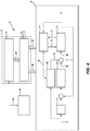
- Fig. 4 shows a flow diagram of a demand management and control system 40 for a gravity fed irrigation network 42 ( Fig. 5 ).
- the system 40 has a user interface 44 which allows customers to select a time frame and flow rate for valves 16, 18 and 20.
- Interface 44 can be a computer, keyboard or an Internet based application to allow the user to enter their requests 46 into system 40.
- the requests 46 and the returned confirmations to the user are monitored by a demand management system 48 implemented in a central computer 50.
- the demand management system 48 includes a real time database that maintains predetermined parameters including flow schedules, capabilities of valves, business and control rules.
- a supervisory layer 52 is also implemented in the central computer 50. Supervisory layer 52 is linked to the demand management system 48 through port 54 and updates and receives flow schedules and constraint information.
- Supervisory layer 52 communicates with each valve 16, 18 and 20 to cause the valves to be controlled through port 56 and to receive the measured flow and performance information through port 58.
- Each valve 16, 18 and 20 has a valve control interface 60 although Fig. 4 only shows one interface 60.
- Each valve control interface 60 can be in the form of a remote terminal unit (RTU) or programmable logic controller (PLC). It is evident that each valve will require a respective valve control interface.
- the location of the respective valve control interface(s) 60 can be with the central computer 50, or remotely located with the respective valve.
- Valve 16 is typically of the type shown in Figs. 17 to 79 of International Patent Application No. PCT/AU2012/000328 . Valve 16 will be associated with a flow meter (not shown), typically of the type shown in International Patent Application No. PCT/AU2010/001052 .
- the advantage of this type of valve is the approximately linear relationship between the valve opening (angular position) and flow. This ensures a relatively accurate flow setting is achieved using the predetermined valve opening.
- Other valve mechanisms such as butterfly valves that are commonly used in the water industry, do not possess this linear characteristic and would therefore have difficulty in achieving the required valve rating (to be described later) and the associated control.
- the preferred embodiment is not limited to these type of valves or flow meters but these valves and flow meters are well suited to the task.
- Each flow meter will provide the measured flow and performance information through port 58.
- Each valve 16 has a feed forward controller 62 and a feedback controller 64 whose outputs 66, 68 cause actuation of valve 16 via signal 69.
- the flow rate is measured by the flow meter (not shown) and sent to port 58, to feedback controller 64 through signal 71 and to a valve calibration section 70.
- the flow order 72 from port 56 for the valve 16 is delivered to both the feed forward controller 62 and the feedback controller 64.
- the feed forward controller 62 will lead the action of the feedback controller 64 using an optional delay switch 74. It is preferred that both the feed forward controller 62 and the feedback controller 64 be provided but the system can also function with only one of these controllers.
- Control strategy for low energy pipelines is one of managing the interactions of the controllers of each valve in a defined control methodology.
- Knowledge of the dynamics of the pipe 14 through the fluid network model will be used to design controllers using already well known classical control theory, and the knowledge of the future demand.
- the valve rating and measurement of the current pressure head conditions in the pipe 14 will be used to feed-forward to the valve 16 movements through controller 62.
- the valve rating is the derived relationship between;
- the valve rating will be calibrated during normal operation by the valve calibration section 70 using the data recorded for the aforementioned parameters during the normal operation of the valve 16.
- the valve rating is derived using System Identification techniques.
- the adjusted valve rating will be sent to valve 16 at 76 and the valve opening will be returned to valve calibration section 70 through signal 78.
- the valve rating allows a predetermined control action to send valve 16 to a particular opening for a known pressure head in order to achieve a desired flow.
- the valve rating facilitates a bulk control adjustment without relying on feedback control using the flow measurement.
- the system 40 provides control such that that hydraulic grade line is biased towards the high end of the spectrum.
- Fig. 6 it shows that valve 16 is operating and valves 18 and 20 are about to open.
- Fig. 6 graphically shows the static, as opposed to the dynamic, operation of the three valves.
- Valve 16 is due to stop at point 82 and valves 18 and 20 are to open at the same time.
- the closing event of valve 16 will be initiated first to make extra pressure head 90 available as can be seen from the accumulative pressure head line 88.
- the closing action of one or more valves will always lead (advance in time) any opening action of other valves.
- This control sequence ensures fluctuations in the pressure head (hydraulic grade line) due to control actions always result in a pressure greater than that predicted by the model and ensures that the pressure head does not drop below that predicted by the model within the demand management system 48. It is important the hydraulic grade line does not drop below a minimum supply level at valve as this can result in the pipe becoming "not full” and flow measurement would likely to be in error. In addition, maintaining the hydraulic grade line above a critical minimum level for valves is an important object of the low energy pipeline to guarantee an ordered flow can be achieved through the network. The command to deliver a flow at the valve will be provided by the demand management system 48 once the order passes the capacity checks.
- the feed-forward controller 62 kicks in first and moves the valve to a best estimate position to deliver the requested flow based on the local pressure head and valve rating.
- the feedback controller 64 only does the fine adjustments. In the preferred embodiment there will be an ability to use the feedback controller 64 or the feed forward controller 62 individually, or in combination as discussed previously. Such a methodology will minimize the transients in the pipeline and hence the interactions. This is a uniqueness of the solution.
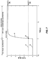
- Fig. 7 is a similar view to that of Fig. 3 showing the stable behaviour of the valves using the system shown in Fig. 4 .
- Line 24 illustrates valve 16 being already open and the effect that the opening of valve 18 has on the network.
- Line 26 illustrates the flow of valve 18. Both valves 16 and 18 are trying to maintain their preselected flow rate.
- the major jittery interaction shown in Fig. 3 at 30 has been substantially reduced in Fig. 7 using the system of this preferred embodiment.
- the jittery interaction show in Fig. 3 at 28 has also been substantially reduced. The improvement in control and steady flows through the valves even when multiple valves are operating is evident.
- the invention can also be used in association with irrigation system that include a hybrid pump for increasing the flow rate when an increase in flow rate is required.
- a hybrid pump for increasing the flow rate when an increase in flow rate is required.
- Such a system is shown in our Australian Patent Application Nos. 2012905225 and 2012905508 .
- Fig. 1 of these applications disclose a main pipeline 20 and a branch pipeline 30 that opens into main pipeline 20.
- the branch pipeline 30 has a low head lift pump 34 that provides an increased flow rate when required by the system.
- An inlet gate 22 on main pipeline 20 will be closed when pump 34 is operating.
- branch pipeline 30 is omitted and an inline pump 36 is provided in the main pipeline 20.
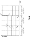
- FIG. 8 The graph shows pressure against time with line 92 showing the cumulative pressure head.
- the hybrid pump is turned on at point 94 but the pressure does not increase until the inlet gate is closed at point 96.
- the pressure will increase to the pressure shown at point 98.
- the increase in pressure will remain whilst the inlet gate is closed and the hybrid pump operates.
- Lines 100, 102 and 104 coincide with the movements of respective valves 20, 18 and 16. Valves 20, 18 and 16 are all open at point 106 at various flow rates and the system 40 will instruct the valves to adjust their valve openings to maintain their respective flow rates as the increased pressure from the hybrid pump is applied.
- the use of a hybrid pump will also have an impact on the hydraulic grade line when the pump is starting up or shutting down.
- the operation of the associated inlet gate (closing) at the pipe inlet allows for the gradual input of the raised pressure head from the pump. This would begin once the pump has been turned on. As the gate closes, the pressure head in the pipeline will increase. This will be undertaken gradually and potentially in a stepwise approach with corresponding offset (leading) valve adjustments occurring at each step. The step and the delay will be a function of the dynamics of the pipe such that valve interactions are kept to a minimum. Similarly the inlet gate could open gradually prior to the pump shutting down. The corresponding offset (lagging) valve adjustments would occur in a sequence with a stepwise opening of the inlet gate. Where there is a control objective to keep the hydraulic grade line below a particular maximum operating pressure the opening of a valve would lead the corresponding closing of another valve. The system would be programmed so that these circumstances can be identified and the appropriate control action taken.
- the supervisory layer 52 will monitor the performance of the pipe network 42 holistically and will have information about the topology.
- the supervisory layer 52 can include high level rules to operate the valves 16, 18, 20 to bias them towards a high pressure head, rules to mitigate the effects of interaction, and rules to follow during exception events. Interactions between controllers for each valve will be monitored by supervisory layer 52 through a further set of rules. Performance will be continuously monitored and deterioration in performance identified. An automatic rule based check will be performed to progressively turn off the feedback component of the valves in the network if control loop interaction is observed until the poorly performing valve is identified. Once identified, the poorly performing valve will have its control suspended, while the others will have the feedback turned back on.
Landscapes
- Engineering & Computer Science (AREA)
- Physics & Mathematics (AREA)
- General Physics & Mathematics (AREA)
- General Engineering & Computer Science (AREA)
- Automation & Control Theory (AREA)
- Theoretical Computer Science (AREA)
- Mechanical Engineering (AREA)
- Databases & Information Systems (AREA)
- Data Mining & Analysis (AREA)
- Mathematical Physics (AREA)
- Software Systems (AREA)
- Structural Engineering (AREA)
- Civil Engineering (AREA)
- Flow Control (AREA)
- Pipeline Systems (AREA)
Description
- The present invention relates to a method of demand management and control for limited pressure head or gravity fed fluid closed conduit networks, and relates particularly, though not exclusively, to a method of demand management and control for limited pressure head or gravity fed water irrigation pipe networks.
- In our
US Patent No. 7,152,001 there is disclosed a computer based system for predicting the fluid level in a fluid flow network. The system has been very successful as it can use past and present measurements of parameters to predict and control fluid level and flow. The system gathers data from timed fluid levels and opening positions of regulators or valves to provide a model from which fluid levels and flow can be determined in real time. - In our International Patent Application No.
PCT/AU2012/000907 WO 2013/016769 ) there is disclosed a method of demand management for fluid networks. The method includes the steps of: - providing a computer controlled fluid network for delivery of fluid to at least one customer;
- maintaining a real time database within the computer controlled fluid network of predetermined parameters;
- requesting a flow rate and time of delivery of said fluid from the fluid network through a user interface to a customer;
- determining, using predetermined parameters from the real time database, the availability of providing delivery of fluid from the fluid network to the customer based on hydraulic capacity of the fluid network; and
- if the hydraulic capacity is available, calculating parameters using the real time database to delivery fluid to the customer through the computer controlled fluid network.
- The method is applicable to both a closed conduits (pipeline network) and open conduits (channel networks). Gravity pipe networks typically operate within limited pressure head and therefore are constrained in their capability to meet demand.
- Known models for pipe networks would be used in the management of demand for these networks. Data from the SCADA system would be used to calibrate and continually fine-tune the model of the pipe conveyance network based on system identification techniques. Flow measurement and pressure head measurements would be located at points on the pipe network that would be deemed necessary to calibrate the model to the desired accuracy. The supply points to users are the primary form of control used with a pipe network. The controller for a pipe network is much simpler than it is for a channel network with the principle form of control being maintaining the flow at the supply point equal to that of the order.
- Control and management of demand is especially applicable to gravity pipe networks commonly used for the supply of irrigation water. Difficulties have arisen to implement such systems as gravity pipe networks typically operate within limited pressure head and therefore are constrained in their capability to continually meet demand. Gravity pipelines also typically operate at lower pressure heads where there will be greater interaction between flows at outlets due to valve operations. Accordingly, assuming all the parameters such as pipe diameter, flow rate, valve size, etc. being the same, the higher the static pressure head (e.g. from pumping), the less sensitive the impact of flow fluctuations due to valve operations (e.g. valves opening or closing) on other valves in operation.
-
Fig. 1 illustrates why operating valves are less sensitive to flow variations in the supply pipeline (e.g. from other opening and closing valves) with a higher pressure head in the pipeline.Fig. 1 shows a graph of the hydraulic grade line or pressure head against the valve position for a high pressure atline 10 and for a low pressure or gravity fed hydraulic grade line or pressure head atline 12. Gravity fedpipe 14 is shown on a grade with twovalves pipe 14 is shown on a grade, it could be horizontal if the water supply is elevated to provide the required pressure head. Forline 10,pipe 14 would be coupled to a pump (not shown) to produce a high-pressure head. The explanation now follows: - 1. Assume the one
physical pipeline 14 operating at either a Low Pressure (LP) state and at a High Pressure (HP) state, and for a specific operating valve supplying fluid off thepipeline 14. - 2. Assume initially the
supply pipeline 14 is operating at the same flow rate Q 1 in both states. - 3. A change in flow in the supply pipeline 14 (due to
other valves 
- 4. The change in pressure head, Δh, at the
operating valve 16 due to the change in flow ΔQ, is the same for both states. (The known pipeline flow versus pressure head equations, e.g. Colebrook-White equation, Manning's Formulae are applicable) - 5. The head loss across
valve 16 is determined as follows:
- h = pressure loss in terms of fluid head, i.e. fluid head loss
- K = the valve 'K' factor (assume constant) for the specified valve opening
- v = velocity of fluid
- g = acceleration due to gravity
- 6. Assume the same initial flow, and therefore velocity, through the
operating valve 16 in both the LP and HP states areequal 

- 7. With h LP1 ≪ h HP1

valve 16 will be at a greater opening in the LP state than the HP state. - 8. When a pressure head change, Δh, is introduced, the change in pressure head across
valve 16 for each state is h LP2 = h LP1 - Δh, and h HP2 = h HP2 - Δh respectively. The relative change in head across the valve is greatest in LP state than the HP state. - 9. Assuming
valve 16 remains in the same opening position for each state, and therefore the K factors remain the same, the new velocity for each state is;

- 10. The resulting velocities for each state due to the pressure head change, Δh, will see;

- Higher pressure (e.g. pumped) pipelines with smaller diameter valves and flow meters have less interaction between operating valves than low-pressure pipelines with larger diameter valves and flow meters. In high pressure systems the valves can be manually positioned to a set opening to achieve a certain flow, and the flow will not be impacted significantly by the operation of the other valves (e.g. valves opening or closing) in the pipeline. Whereas, low-pressure pipelines require an integrated control and demand management system to manage the valve interaction within the tight hydraulic grade line conditions.
-
Fig. 2 showspipeline 14 separated fromFig. 1 and illustrates themaximum supply pressure 22 which must maintain the pipeline full to ensure the accuracy of the flow meters (not shown) associated withvalves hydraulic grade line 12 associated with thepipeline 14 above themaximum supply pressure 22 will also ensure that the pressure head at thevalves hydraulic grade line 12 associated withpipeline 14 will potentially result in increased controller interaction between the discrete control actions necessary to maintain desired flows at the valves. This is further compounded with gravity pipelines where the flow capacity at the valves is high in relation to the overall flow capacity of the main trunk pipeline. The action of opening or closing valves will impact the pressure head, and therefore flow, at all other valves on thepipeline 14 that are operating. Therefore there will be interaction between various automated valves operating off the pipeline. In this low energy pipeline, the control will be subject to instability. Each movement in a valve has a level of interaction with all the other operating valves plus supply level variation at the source or at the outlet (on-farm). Because of the low pressure in thepipeline 14, thehydraulic grade line 12 is very sensitive to the operation of the valve/outlets. - This sensitivity is illustrated in
Fig. 3 where a graph of flow and time is shown.Line 24 illustratesvalve 16 being already open and the effect that the opening ofvalve 18 has on the network.Line 26 illustrates the flow ofvalve 18. Bothvalves valve 16 shown by the changes in flow at 28 but there is a major interaction on the stability of flow throughvalve 18 shown by the changes in flow at 30. Furthermore, all the additional valves e.g.valve 20 will also be effected by this interaction. The network becomes extremely unstable and this is a key reason why gravity feed irrigation systems have found little favour with water suppliers and users. - It is an object of the present invention to provide a method of demand management and control of limited pressure head or gravity fed fluid pipe networks for closed conduit fluid networks to maintain a requested flow rate despite variations in the pressure head in said fluid network.
- A further object of the present invention to provide a method of demand management and control of limited pressure head or gravity fed fluid pipe networks for closed conduit fluid networks that avoids instability that can occur from the interaction between operating valves.
- The present invention in one aspect provides a method of demand management and control of limited pressure head or gravity fed fluid pipe networks, said method including the steps of providing a computer controlled fluid network for delivery of fluid through a plurality of valves, maintaining a real time database within said computer controlled fluid network of predetermined parameters including flow schedules and capabilities of said plurality of valves, requesting, through a user interface, a flow rate and time of delivery of said fluid from the fluid network to at least one of said plurality of valves, determining, using said predetermined parameters from said real time database, the availability of providing said delivery and flow rate of said fluid from the fluid network to said at least one of said plurality of valves based on hydraulic capacity of said fluid network, and, if said hydraulic capacity is available, calculating parameters using said real time database to deliver said fluid to said at least one of said plurality of valves through said computer controlled fluid network, whereby each of said plurality of valves is monitored and adjustably controlled to provide said flow rate and delivery through said at least one of said plurality of valves in unison with the monitoring and controlling of the others of said plurality of valves to maintain the flow and manage the pressure head within said fluid pipe network between predetermined limits.
- Preferably the method further includes pre-empting the valve position of at least one of the others of said plurality of operating valves to maintain their flow rate in anticipation of the variation of pressure head in the fluid pipe network due to said delivery through said at least one of said plurality of valves. The method may also include a respective feedback controller associated with each of said plurality of valves to allow fine-tuning of the valve position of each valve. A respective feed-forward controller may also be provided to vary the valve position of said valves to a best estimate position based on one or more of the following: monitored hydraulic capacity of said fluid pipe network; predicted pressure head change at the respective valves based on future flow schedule maintained in the real time database; and valve rating associated with the respective valves. It is proposed that said feed-forward and feedback controllers are associated with respective valves.
- The invention may also use data from an interface to calibrate and continually fine tune the valve rating for the respective valves using data fitting techniques.
- In yet a further embodiment there is provided a supervisory control layer within said computer control to monitor and control the feed-forward and feedback controllers for each valve, to prevent the interaction between the various operating valves, maintain the pressure head within said fluid pipe network between predetermined limits, and handle exception events as per predetermined business rules.
- Preferably the method further includes the steps of allowing a plurality of customers to access said user interface and said computer controlled fluid network determining a priority and weighting of flow rate and time of delivery requests of said fluid to ensure continuance of said hydraulic capacity. The priority and weighting of delivery requests may include tariff structures for said customers based on best use of available hydraulic capacity.
- In a further embodiment data from an interface is used to calibrate and continually fine tune the computer controlled fluid network using a model of the fluid pipe network based on system identification techniques. The method may also include the step of rescheduling said flow rate and time of delivery of said fluid from the fluid network if said hydraulic capacity is not available.
- In a practical embodiment the method includes the step of said computer controlled fluid network controlling operation of a hybrid pump to maintain pressure head. The plurality of valves may include bi-foldable barrier members pivoting along a central axis to provide an approximate linear relationship between the opening of the bi-foldable barrier members and the fluid flow.
- Preferably said predetermined parameters includes business rules and constraints to allow for further variations of said flow rate and time of delivery of said fluid through any valve. The method may include the step of any subsequent flow rate and time delivery request resulting in the maximum and minimum thresholds of flow limits through said fluid network being breached will be denied or rescheduled to allow said subsequent request to proceed based on said calculated parameters.
- The invention also provides a method of demand management and control of limited pressure head or gravity fed fluid pipe networks, said method including the steps of providing a computer controlled fluid network for delivery of fluid through a plurality of valves, maintaining a real time database within said computer controlled fluid network of predetermined parameters including flow schedules and capabilities of said plurality of valves to provide a model of the fluid pipe network, requesting, through a user interface, a flow rate and time of delivery of said fluid from the fluid network to at least one of said plurality of valves, determining, using said predetermined parameters from said real time database, the availability of providing said delivery and flow rate of said fluid from the fluid network to said at least one of said plurality of valves based on hydraulic capacity of said fluid network, and, if said hydraulic capacity is available, calculating parameters using said real time database to deliver said fluid to said at least one of said plurality of valves through said computer controlled fluid network, whereby each of said plurality of valves is monitored and adjustably controlled to provide said flow rate and delivery through said at least one of said plurality of valves in unison with the monitoring and controlling of the others of said plurality of valves to maintain the flow and manage the pressure head within said fluid pipe network between predetermined limits.
- The invention also relates to a system that uses the methods as previously described.
- The structure and functional features of a preferred embodiment of the present invention will become more apparent from the following detailed description when taken in conjunction with the accompanying drawing, in which: -
-
Fig. 1 is a graph of the hydraulic grade line or pressure head against the valve position for a high pressure irrigation system and for a low pressure or gravity fed hydraulic grade line or pressure head irrigation system; -
Fig. 2 shows a schematic drawing of the low pressure or gravity fed hydraulic grade line or pressure head irrigation system with the valves and hydraulic grade line; -
Fig. 3 is a graph of the flow and time for switching of valves shown inFig. 2 showing the unstable behavior of the valves; -
Fig. 4 is a block diagram of the architecture of the low pressure or gravity fed irrigation system according to a preferred embodiment of the present invention; -
Fig. 5 is a similar drawing to that ofFig. 4 overlaid with a low pressure or gravity fed pipeline; -
Fig. 6 is graphical representation of the valve operation to bias towards a high pressure head; -
Fig. 7 is a similar view to that ofFig. 3 showing the stable behavior of the valves using the system shown inFig. 4 ; and -
Fig. 8 is a graphical representation where a hybrid pump is installed in the low pressure or gravity fed irrigation system. -
Fig. 4 shows a flow diagram of a demand management andcontrol system 40 for a gravity fed irrigation network 42 (Fig. 5 ). Thesystem 40 has auser interface 44 which allows customers to select a time frame and flow rate forvalves system 40.Interface 44 can be a computer, keyboard or an Internet based application to allow the user to enter theirrequests 46 intosystem 40. Therequests 46 and the returned confirmations to the user are monitored by ademand management system 48 implemented in acentral computer 50. Thedemand management system 48 includes a real time database that maintains predetermined parameters including flow schedules, capabilities of valves, business and control rules. Asupervisory layer 52 is also implemented in thecentral computer 50.Supervisory layer 52 is linked to thedemand management system 48 throughport 54 and updates and receives flow schedules and constraint information. -
Supervisory layer 52 communicates with eachvalve port 56 and to receive the measured flow and performance information throughport 58. Eachvalve Fig. 4 only shows one interface 60. Each valve control interface 60 can be in the form of a remote terminal unit (RTU) or programmable logic controller (PLC). It is evident that each valve will require a respective valve control interface. The location of the respective valve control interface(s) 60 can be with thecentral computer 50, or remotely located with the respective valve. -
Valve 16 is typically of the type shown in Figs. 17 to 79 of International Patent Application No.PCT/AU2012/000328 Valve 16 will be associated with a flow meter (not shown), typically of the type shown in International Patent Application No.PCT/AU2010/001052 port 58. Eachvalve 16 has afeed forward controller 62 and afeedback controller 64 whoseoutputs 66, 68 cause actuation ofvalve 16 viasignal 69. The flow rate is measured by the flow meter (not shown) and sent toport 58, tofeedback controller 64 throughsignal 71 and to avalve calibration section 70. Theflow order 72 fromport 56 for thevalve 16 is delivered to both the feed forwardcontroller 62 and thefeedback controller 64. Typically, the feed forwardcontroller 62 will lead the action of thefeedback controller 64 using anoptional delay switch 74. It is preferred that both the feed forwardcontroller 62 and thefeedback controller 64 be provided but the system can also function with only one of these controllers. - Control strategy for low energy pipelines is one of managing the interactions of the controllers of each valve in a defined control methodology. Knowledge of the dynamics of the
pipe 14 through the fluid network model will be used to design controllers using already well known classical control theory, and the knowledge of the future demand. The valve rating and measurement of the current pressure head conditions in thepipe 14 will be used to feed-forward to thevalve 16 movements throughcontroller 62. The valve rating is the derived relationship between; - the valve opening,
- the differential pressure head at the
valve 16; and - the flow.
- The valve rating will be calibrated during normal operation by the
valve calibration section 70 using the data recorded for the aforementioned parameters during the normal operation of thevalve 16. The valve rating is derived using System Identification techniques. The adjusted valve rating will be sent tovalve 16 at 76 and the valve opening will be returned tovalve calibration section 70 throughsignal 78. The valve rating allows a predetermined control action to sendvalve 16 to a particular opening for a known pressure head in order to achieve a desired flow. The valve rating facilitates a bulk control adjustment without relying on feedback control using the flow measurement. - The
system 40 provides control such that that hydraulic grade line is biased towards the high end of the spectrum. With reference toFig. 6 it shows thatvalve 16 is operating andvalves Fig. 6 graphically shows the static, as opposed to the dynamic, operation of the three valves.Valve 16 is due to stop atpoint 82 andvalves valves points valve 16 will be initiated first to makeextra pressure head 90 available as can be seen from the accumulativepressure head line 88. Thus the closing action of one or more valves will always lead (advance in time) any opening action of other valves. This control sequence ensures fluctuations in the pressure head (hydraulic grade line) due to control actions always result in a pressure greater than that predicted by the model and ensures that the pressure head does not drop below that predicted by the model within thedemand management system 48. It is important the hydraulic grade line does not drop below a minimum supply level at valve as this can result in the pipe becoming "not full" and flow measurement would likely to be in error. In addition, maintaining the hydraulic grade line above a critical minimum level for valves is an important object of the low energy pipeline to guarantee an ordered flow can be achieved through the network. The command to deliver a flow at the valve will be provided by thedemand management system 48 once the order passes the capacity checks. When the time arrives to open the valve, the feed-forward controller 62 kicks in first and moves the valve to a best estimate position to deliver the requested flow based on the local pressure head and valve rating. Thefeedback controller 64 only does the fine adjustments. In the preferred embodiment there will be an ability to use thefeedback controller 64 or the feed forwardcontroller 62 individually, or in combination as discussed previously. Such a methodology will minimize the transients in the pipeline and hence the interactions. This is a uniqueness of the solution. -
Fig. 7 is a similar view to that ofFig. 3 showing the stable behaviour of the valves using the system shown inFig. 4 .Line 24 illustratesvalve 16 being already open and the effect that the opening ofvalve 18 has on the network.Line 26 illustrates the flow ofvalve 18. Bothvalves Fig. 3 at 30 has been substantially reduced inFig. 7 using the system of this preferred embodiment. Similarly, the jittery interaction show inFig. 3 at 28 has also been substantially reduced. The improvement in control and steady flows through the valves even when multiple valves are operating is evident. - The invention can also be used in association with irrigation system that include a hybrid pump for increasing the flow rate when an increase in flow rate is required. Such a system is shown in our Australian Patent Application Nos.
2012905225 2012905508 Fig. 1 of these applications disclose amain pipeline 20 and abranch pipeline 30 that opens intomain pipeline 20. Thebranch pipeline 30 has a low head lift pump 34 that provides an increased flow rate when required by the system. Aninlet gate 22 onmain pipeline 20 will be closed when pump 34 is operating. InFig. 3 of these applications a further embodiment is shown wherebranch pipeline 30 is omitted and an inline pump 36 is provided in themain pipeline 20. The effect of the hybrid pump 34 ofFig. 1 withinlet gate 22 of Australian Patent Application Nos.2012905225 2012905508 Fig. 8 . The graph shows pressure against time withline 92 showing the cumulative pressure head. The hybrid pump is turned on atpoint 94 but the pressure does not increase until the inlet gate is closed atpoint 96. The pressure will increase to the pressure shown atpoint 98. The increase in pressure will remain whilst the inlet gate is closed and the hybrid pump operates.Lines respective valves Valves point 106 at various flow rates and thesystem 40 will instruct the valves to adjust their valve openings to maintain their respective flow rates as the increased pressure from the hybrid pump is applied. - The use of a hybrid pump will also have an impact on the hydraulic grade line when the pump is starting up or shutting down. The operation of the associated inlet gate (closing) at the pipe inlet allows for the gradual input of the raised pressure head from the pump. This would begin once the pump has been turned on. As the gate closes, the pressure head in the pipeline will increase. This will be undertaken gradually and potentially in a stepwise approach with corresponding offset (leading) valve adjustments occurring at each step. The step and the delay will be a function of the dynamics of the pipe such that valve interactions are kept to a minimum. Similarly the inlet gate could open gradually prior to the pump shutting down. The corresponding offset (lagging) valve adjustments would occur in a sequence with a stepwise opening of the inlet gate. Where there is a control objective to keep the hydraulic grade line below a particular maximum operating pressure the opening of a valve would lead the corresponding closing of another valve. The system would be programmed so that these circumstances can be identified and the appropriate control action taken.
- The
supervisory layer 52 will monitor the performance of thepipe network 42 holistically and will have information about the topology. Thesupervisory layer 52 can include high level rules to operate thevalves supervisory layer 52 through a further set of rules. Performance will be continuously monitored and deterioration in performance identified. An automatic rule based check will be performed to progressively turn off the feedback component of the valves in the network if control loop interaction is observed until the poorly performing valve is identified. Once identified, the poorly performing valve will have its control suspended, while the others will have the feedback turned back on. - Throughout this specification and the claims which follow, unless the context requires otherwise, the word "comprise", and variations such as "comprises" and "comprising", will be understood to imply the inclusion of a stated integer or step or group of integers or steps but not the exclusion of any other integer or step or group of integers or steps.
- The reference to any prior art in this specification is not and should not be taken as an acknowledgement or any form of suggestion that the prior art forms part of the common general knowledge in Australia.
Claims (14)
- A method of demand management and control of a pipe network (42);
the pipe network being a computer controlled fluid network and of limited pressure head or gravity fed;
the pipe network including a plurality of valves (16, 18, 20) through which fluid is deliverable;
the valves being automated to maintain desired flows at the valves;
the method includingmaintaining predetermined parameters including flow schedules and capabilities of the plurality of valves in a real time database within said computer controlled fluid network; andreceiving through a user interface (44) a request for a delivery of the fluid from at least one (18) of the valves;the request including a flow rate and a time of the delivery;the method further includingdetermining, using the predetermined parameters from the real time database, whether the network has hydraulic capacity to deliver the requested flow rate; andif said hydraulic capacity is available, calculating parameters using said real time database to deliver said fluid, monitoring and adjustably controlling the at least one valve and at least one other (16) of the plurality of valves to deliver the requested flow rate and to maintain the desired flows and manage pressure head within the fluid pipe network between predetermined limits;characterised in that the method further comprises:fine tuning by a respective feedback controller (64) associated with each of the plurality of valves the position of each of the plurality of valves;varying by a respective feed-forward controller (62) the valve position of each of the plurality of valves to an estimated position based on monitored hydraulic capacity of the pipe network, predicted pressure head change at the respective valves based on the flow schedules maintained in the real time database and valve rating associated with the respective valve. - The method of claim 1 including moving at least one other of the plurality of valves in anticipation of a variation of pressure head in the fluid pipe network due to the delivery.
- The method of any one of the preceding claims, further including the steps of allowing a plurality of customers to access said user interface; and
the computer controlled fluid network determining a priority and weighting of flow rate and time of delivery requests of the fluid to ensure continuance of said hydraulic capacity. - The method of claim 3 wherein said priority and weighting of delivery requests include tariff structures for said customers based on best use of available hydraulic capacity.
- The method of any one of the preceding claims, wherein data from an interface is used to calibrate and continually fine tune the computer controlled fluid network using a model of the fluid pipe network based on system identification techniques.
- The method of any one of the preceding claims, further including the step of rescheduling said flow rate and time of delivery of said fluid from the fluid network if said hydraulic capacity is not available.
- The method of any one of the preceding claims, including the step of said computer controlled fluid network controlling operation of a hybrid pump to maintain pressure head.
- The method of any one of the preceding claims, said plurality of valves include bi-foldable barrier members pivoting along a central axis to provide an approximately linear relationship between the opening of the bi-foldable barrier members and the fluid flow.
- The method of any one of the preceding claims, wherein said predetermined parameters include business rules and constraints to allow for further variations of said flow rate and time of delivery of said fluid through any valve.
- The method of any one of the preceding claims, wherein any subsequent flow rate and time delivery request resulting in the maximum and minimum thresholds of flow limits through said fluid network being breached will be denied or rescheduled to allow said subsequent request to proceed based on said calculated parameters.
- The method of any one of claims 1 to 10 wherein the request is a request for irrigation water.
- The method of any one of claims 1 to 11 wherein the predetermined limits of the pressure head do not fall below a predicted pressure to maintain the pipe network full.
- A demand management and control system (40) for demand management and control of a pipe network (42);
the pipe network being a fluid network and of limited pressure head or gravity fed;
the pipe network including a plurality of valves (16, 18, 20) through which fluid is deliverable;
the valves being automated to maintain desired flows at the valves;
the system including a computer (50) configured tomaintain predetermined parameters including flow schedules and capabilities of the plurality of valves in a real time database within said computer controlled fluid network; andreceive through a user interface (44) a request for a delivery of the fluid from at least one (13) of the valves;the request including a flow rate and a time of the delivery;
the computer being further configured todetermine, using the predetermined parameters from the real time database, whether the network has hydraulic capacity to deliver the requested flow rate; andif said hydraulic capacity is available, monitor and adjustably control the at least one valve and at least one other (16) of the plurality of valves to deliver the requested flow rate and to maintain the desired flows and manage pressure head within the fluid pipe network between predetermined limits;characterised in that the demand management and control system further comprises:a respective feedback controller (64) associated with each of the plurality of valves and configured to fine-tune the position of each of the plurality of valves;a respective feed-forward controller (62) configured to vary the valve position of each of the plurality of valves to an estimated position based on monitored hydraulic capacity of the pipe network, predicted pressure head change at the respective valves based on the flow schedules maintained in the real time database and valve rating associated with the respective valve. - A fluid delivery system (42, 50) including the demand management and control system of claim 13 and the pipe network.
Applications Claiming Priority (2)
| Application Number | Priority Date | Filing Date | Title |
|---|---|---|---|
| AU2013903383A AU2013903383A0 (en) | 2013-09-04 | Method of demand management and control of fluid pipe networks | |
| PCT/AU2014/050208 WO2015031954A1 (en) | 2013-09-04 | 2014-09-04 | Method of demand management and control of fluid pipe networks |
Publications (3)
| Publication Number | Publication Date |
|---|---|
| EP3041997A1 EP3041997A1 (en) | 2016-07-13 |
| EP3041997A4 EP3041997A4 (en) | 2017-04-19 |
| EP3041997B1 true EP3041997B1 (en) | 2020-01-22 |
Family
ID=52627619
Family Applications (1)
| Application Number | Title | Priority Date | Filing Date |
|---|---|---|---|
| EP14841712.4A Active EP3041997B1 (en) | 2013-09-04 | 2014-09-04 | Method of demand management and control of fluid pipe networks |
Country Status (14)
| Country | Link |
|---|---|
| US (1) | US10114388B2 (en) |
| EP (1) | EP3041997B1 (en) |
| CN (2) | CN107574785B (en) |
| AU (1) | AU2014317812B2 (en) |
| BR (1) | BR112016004819B1 (en) |
| CA (1) | CA2922906C (en) |
| CL (1) | CL2016000491A1 (en) |
| EA (1) | EA032370B1 (en) |
| ES (1) | ES2786903T3 (en) |
| MA (1) | MA38924B1 (en) |
| MX (1) | MX371038B (en) |
| NZ (1) | NZ718357A (en) |
| PE (1) | PE20160346A1 (en) |
| WO (1) | WO2015031954A1 (en) |
Families Citing this family (12)
| Publication number | Priority date | Publication date | Assignee | Title |
|---|---|---|---|---|
| GB2545899B (en) * | 2015-12-21 | 2018-07-25 | Imperial Innovations Ltd | Management of liquid conduit systems |
| CN106647289B (en) * | 2017-03-06 | 2019-09-10 | 武汉大学 | The feed forward control method of gate delay opening and closing time is dispatched in open channel water delivery |
| US9897259B1 (en) | 2017-04-18 | 2018-02-20 | Air Products And Chemicals, Inc. | Control system in a gas pipeline network to satisfy pressure constraints |
| US9897260B1 (en) | 2017-04-18 | 2018-02-20 | Air Products And Chemicals, Inc. | Control system in an industrial gas pipeline network to satisfy energy consumption constraints at production plants |
| US9915399B1 (en) | 2017-04-18 | 2018-03-13 | Air Products And Chemicals, Inc. | Control system in a gas pipeline network to satisfy demand constraints |
| US9890908B1 (en) * | 2017-04-18 | 2018-02-13 | Air Products And Chemicals, Inc. | Control system in a gas pipeline network to increase capacity factor |
| US10415760B2 (en) | 2017-04-18 | 2019-09-17 | Air Products And Chemicals, Inc. | Control system in an industrial gas pipeline network to satisfy energy consumption constraints at production plants |
| CN111163629B (en) | 2017-08-14 | 2022-08-19 | 鲁比康研究有限公司 | Method and system for water distribution and soil moisture determination |
| US11972176B2 (en) | 2018-11-09 | 2024-04-30 | Schlumberger Technology Corporation | Pipeline network solving using decomposition procedure |
| EP4004290B1 (en) | 2019-07-26 | 2025-11-26 | Rubicon Research Pty Ltd | Multi pulley control gate |
| US12444189B2 (en) | 2021-12-14 | 2025-10-14 | Rubicon Research Pty Ltd | Methods and systems for classifying and benchmarking irrigation performance |
| CN115017666B (en) * | 2022-08-08 | 2022-11-01 | 廊坊市清泉供水有限责任公司 | Intelligent operation method and system for underground water source |
Family Cites Families (20)
| Publication number | Priority date | Publication date | Assignee | Title |
|---|---|---|---|---|
| JPH09217900A (en) | 1995-12-06 | 1997-08-19 | Hitachi Ltd | Fluid transport network control system and method |
| US5941305A (en) * | 1998-01-29 | 1999-08-24 | Patton Enterprises, Inc. | Real-time pump optimization system |
| EP2028577A2 (en) * | 1999-04-16 | 2009-02-25 | Fujikin Incorporated | Parallel bypass type fluid feeding device, and method and device for controlling fluid variable type pressure system flow rate used for the device |
| US6568416B2 (en) * | 2001-02-28 | 2003-05-27 | Brian L. Andersen | Fluid flow control system, fluid delivery and control system for a fluid delivery line, and method for controlling pressure oscillations within fluid of a fluid delivery line |
| AUPR353801A0 (en) | 2001-03-02 | 2001-03-29 | Rubicon Systems Australia Pty Ltd | Fluid regulation |
| AU2003296510A1 (en) * | 2002-12-10 | 2004-06-30 | Et Water Systems, Llc | Irrigation system |
| US7647136B2 (en) * | 2006-09-28 | 2010-01-12 | Exxonmobil Research And Engineering Company | Method and apparatus for enhancing operation of a fluid transport pipeline |
| GB2459603B (en) | 2007-01-24 | 2011-12-07 | I2O Water Ltd | Controller and control system for a pressure reducing valve |
| GB0701352D0 (en) | 2007-01-24 | 2007-03-07 | Hydrodigital Ltd | Liquid pressure control |
| KR20090002115A (en) * | 2007-06-18 | 2009-01-09 | 주식회사 케이티 | Flow measurement service using fiber optic sensor and oil distribution service system and method through network |
| JP5677842B2 (en) * | 2007-09-06 | 2015-02-25 | デカ・プロダクツ・リミテッド・パートナーシップ | Processing system and method |
| US8406945B2 (en) | 2007-10-26 | 2013-03-26 | GM Global Technology Operations LLC | Method and apparatus to control logic valves for hydraulic flow control in an electro-mechanical transmission |
| JP4846749B2 (en) * | 2008-03-11 | 2011-12-28 | 富士フイルム株式会社 | Recording tape cartridge |
| EP4567383A3 (en) | 2009-08-18 | 2025-09-03 | Rubicon Research, Pty.Ltd. | Flow meter assembly, gate assemblies and methods of flow measurement |
| CN101872161A (en) * | 2010-04-30 | 2010-10-27 | 浙江大学 | A Virtual Reality-Based Interactive Control Method for Key Devices in Process Industry |
| CN101858095B (en) | 2010-06-10 | 2012-01-11 | 上海三高计算机中心股份有限公司 | Processing method and device for providing auxiliary dispatching data of water supply network |
| CN105952958B (en) | 2011-04-01 | 2019-12-03 | 鲁比康研究有限公司 | Cable drives, control doors and fluid control dampers |
| EP2740063B1 (en) * | 2011-08-02 | 2021-03-10 | Rubicon Research, Pty.Ltd. | Demand management system for fluid networks |
| WO2013149304A1 (en) * | 2012-04-05 | 2013-10-10 | Rubicon Research Pty Ltd | Supervisory control of automated irrigation channels |
| AU2013351909B2 (en) | 2012-11-30 | 2017-09-07 | Rubicon Research Pty Ltd | Pipeline system for fluids |
-
2014
- 2014-09-04 US US14/916,181 patent/US10114388B2/en active Active
- 2014-09-04 CN CN201710785898.1A patent/CN107574785B/en not_active Expired - Fee Related
- 2014-09-04 EP EP14841712.4A patent/EP3041997B1/en active Active
- 2014-09-04 WO PCT/AU2014/050208 patent/WO2015031954A1/en not_active Ceased
- 2014-09-04 CA CA2922906A patent/CA2922906C/en active Active
- 2014-09-04 CN CN201480055328.1A patent/CN105612289A/en active Pending
- 2014-09-04 PE PE2016000341A patent/PE20160346A1/en unknown
- 2014-09-04 BR BR112016004819-9A patent/BR112016004819B1/en active IP Right Grant
- 2014-09-04 ES ES14841712T patent/ES2786903T3/en active Active
- 2014-09-04 AU AU2014317812A patent/AU2014317812B2/en active Active
- 2014-09-04 MA MA38924A patent/MA38924B1/en unknown
- 2014-09-04 EA EA201690426A patent/EA032370B1/en unknown
- 2014-09-04 MX MX2016002889A patent/MX371038B/en active IP Right Grant
- 2014-09-04 NZ NZ718357A patent/NZ718357A/en unknown
-
2016
- 2016-03-03 CL CL2016000491A patent/CL2016000491A1/en unknown
Non-Patent Citations (1)
| Title |
|---|
| None * |
Also Published As
| Publication number | Publication date |
|---|---|
| EA201690426A1 (en) | 2016-08-31 |
| MA38924A1 (en) | 2017-02-28 |
| EP3041997A4 (en) | 2017-04-19 |
| CN107574785A (en) | 2018-01-12 |
| PE20160346A1 (en) | 2016-05-11 |
| EA032370B1 (en) | 2019-05-31 |
| MX2016002889A (en) | 2016-07-05 |
| CN107574785B (en) | 2021-06-18 |
| US20160209851A1 (en) | 2016-07-21 |
| BR112016004819B1 (en) | 2021-11-30 |
| WO2015031954A1 (en) | 2015-03-12 |
| CN105612289A (en) | 2016-05-25 |
| BR112016004819A8 (en) | 2020-02-11 |
| AU2014317812A1 (en) | 2016-04-21 |
| CL2016000491A1 (en) | 2016-10-07 |
| EP3041997A1 (en) | 2016-07-13 |
| MX371038B (en) | 2020-01-14 |
| CA2922906C (en) | 2021-06-08 |
| ES2786903T3 (en) | 2020-10-14 |
| MA38924B1 (en) | 2017-09-29 |
| AU2014317812B2 (en) | 2017-08-31 |
| NZ718357A (en) | 2022-11-25 |
| CA2922906A1 (en) | 2015-03-12 |
| US10114388B2 (en) | 2018-10-30 |
Similar Documents
| Publication | Publication Date | Title |
|---|---|---|
| US10114388B2 (en) | Method of demand management and control of fluid pipe networks | |
| EP2740063B1 (en) | Demand management system for fluid networks | |
| CN104321705B (en) | Automated monitoring of irrigation canals | |
| Giustolisi et al. | Strategies for the electric regulation of pressure control valves | |
| CN102239359B (en) | gas supply method | |
| Xu | Model predictive control of an irrigation canal using dynamic target trajectory | |
| Nerantzis et al. | Adaptive model predictive control for fire incidents in water distribution networks | |
| US20180274961A1 (en) | Apparatus and method for creating inferential process flow measurements using other process measurements | |
| JP3959935B2 (en) | Flow control apparatus and method | |
| Clemmens et al. | Application of software for automatic canal management (SacMan) to the WM lateral canal | |
| JP6477268B2 (en) | Flow control device, flow control system, flow control program, and flow control method | |
| JP2013253651A (en) | Liquefied gas discharge equipment | |
| KR102951971B1 (en) | SMART AI water energy management system and method based on network analysis | |
| JPH01251211A (en) | Controller for water distribution pipe network | |
| Munir et al. | Evaluation of hydraulic performance of downstream‐controlled maira‐phlc irrigation canals under crop‐based irrigation operations | |
| Bibok et al. | Hydraulic model calibration of pressure reduced zones with multiple input valves | |
| Letunov et al. | Application of Proportional, Integral, Derivative PID Control Loop Algorithm for Optimization of Equipment Operation Used for Decentralized Water Injection System at West Qurna 2 Oilfield | |
| JPH02268305A (en) | Distributing pipe network controller | |
| Clemmens | Progress on canal automation for water delivery modernization |
Legal Events
| Date | Code | Title | Description |
|---|---|---|---|
| PUAI | Public reference made under article 153(3) epc to a published international application that has entered the european phase |
Free format text: ORIGINAL CODE: 0009012 |
|
| 17P | Request for examination filed |
Effective date: 20160330 |
|
| AK | Designated contracting states |
Kind code of ref document: A1 Designated state(s): AL AT BE BG CH CY CZ DE DK EE ES FI FR GB GR HR HU IE IS IT LI LT LU LV MC MK MT NL NO PL PT RO RS SE SI SK SM TR |
|
| AX | Request for extension of the european patent |
Extension state: BA ME |
|
| DAX | Request for extension of the european patent (deleted) | ||
| REG | Reference to a national code |
Ref country code: DE Ref legal event code: R079 Ref document number: 602014060455 Country of ref document: DE Free format text: PREVIOUS MAIN CLASS: E02B0001000000 Ipc: E02B0013000000 |
|
| A4 | Supplementary search report drawn up and despatched |
Effective date: 20170322 |
|
| RIC1 | Information provided on ipc code assigned before grant |
Ipc: E02B 13/00 20060101AFI20170316BHEP Ipc: G05D 7/06 20060101ALI20170316BHEP Ipc: G05B 19/00 20060101ALI20170316BHEP Ipc: F17D 1/00 20060101ALI20170316BHEP |
|
| STAA | Information on the status of an ep patent application or granted ep patent |
Free format text: STATUS: EXAMINATION IS IN PROGRESS |
|
| 17Q | First examination report despatched |
Effective date: 20190208 |
|
| GRAP | Despatch of communication of intention to grant a patent |
Free format text: ORIGINAL CODE: EPIDOSNIGR1 |
|
| STAA | Information on the status of an ep patent application or granted ep patent |
Free format text: STATUS: GRANT OF PATENT IS INTENDED |
|
| RAP1 | Party data changed (applicant data changed or rights of an application transferred) |
Owner name: RUBICON RESEARCH PTY LTD. |
|
| RIN1 | Information on inventor provided before grant (corrected) |
Inventor name: CHOY, SUMITH Inventor name: AUGHTON, DAVID, JOHN |
|
| INTG | Intention to grant announced |
Effective date: 20190920 |
|
| GRAS | Grant fee paid |
Free format text: ORIGINAL CODE: EPIDOSNIGR3 |
|
| GRAA | (expected) grant |
Free format text: ORIGINAL CODE: 0009210 |
|
| STAA | Information on the status of an ep patent application or granted ep patent |
Free format text: STATUS: THE PATENT HAS BEEN GRANTED |
|
| RAP1 | Party data changed (applicant data changed or rights of an application transferred) |
Owner name: RUBICON RESEARCH PTY LTD. |
|
| AK | Designated contracting states |
Kind code of ref document: B1 Designated state(s): AL AT BE BG CH CY CZ DE DK EE ES FI FR GB GR HR HU IE IS IT LI LT LU LV MC MK MT NL NO PL PT RO RS SE SI SK SM TR |
|
| REG | Reference to a national code |
Ref country code: GB Ref legal event code: FG4D |
|
| REG | Reference to a national code |
Ref country code: CH Ref legal event code: EP |
|
| REG | Reference to a national code |
Ref country code: AT Ref legal event code: REF Ref document number: 1226976 Country of ref document: AT Kind code of ref document: T Effective date: 20200215 |
|
| REG | Reference to a national code |
Ref country code: IE Ref legal event code: FG4D |
|
| REG | Reference to a national code |
Ref country code: DE Ref legal event code: R096 Ref document number: 602014060455 Country of ref document: DE |
|
| REG | Reference to a national code |
Ref country code: RO Ref legal event code: EPE |
|
| REG | Reference to a national code |
Ref country code: NL Ref legal event code: MP Effective date: 20200122 |
|
| REG | Reference to a national code |
Ref country code: LT Ref legal event code: MG4D |
|
| PG25 | Lapsed in a contracting state [announced via postgrant information from national office to epo] |
Ref country code: RS Free format text: LAPSE BECAUSE OF FAILURE TO SUBMIT A TRANSLATION OF THE DESCRIPTION OR TO PAY THE FEE WITHIN THE PRESCRIBED TIME-LIMIT Effective date: 20200122 Ref country code: NL Free format text: LAPSE BECAUSE OF FAILURE TO SUBMIT A TRANSLATION OF THE DESCRIPTION OR TO PAY THE FEE WITHIN THE PRESCRIBED TIME-LIMIT Effective date: 20200122 Ref country code: FI Free format text: LAPSE BECAUSE OF FAILURE TO SUBMIT A TRANSLATION OF THE DESCRIPTION OR TO PAY THE FEE WITHIN THE PRESCRIBED TIME-LIMIT Effective date: 20200122 Ref country code: PT Free format text: LAPSE BECAUSE OF FAILURE TO SUBMIT A TRANSLATION OF THE DESCRIPTION OR TO PAY THE FEE WITHIN THE PRESCRIBED TIME-LIMIT Effective date: 20200614 Ref country code: NO Free format text: LAPSE BECAUSE OF FAILURE TO SUBMIT A TRANSLATION OF THE DESCRIPTION OR TO PAY THE FEE WITHIN THE PRESCRIBED TIME-LIMIT Effective date: 20200422 |
|
| PG25 | Lapsed in a contracting state [announced via postgrant information from national office to epo] |
Ref country code: SE Free format text: LAPSE BECAUSE OF FAILURE TO SUBMIT A TRANSLATION OF THE DESCRIPTION OR TO PAY THE FEE WITHIN THE PRESCRIBED TIME-LIMIT Effective date: 20200122 Ref country code: LV Free format text: LAPSE BECAUSE OF FAILURE TO SUBMIT A TRANSLATION OF THE DESCRIPTION OR TO PAY THE FEE WITHIN THE PRESCRIBED TIME-LIMIT Effective date: 20200122 Ref country code: BG Free format text: LAPSE BECAUSE OF FAILURE TO SUBMIT A TRANSLATION OF THE DESCRIPTION OR TO PAY THE FEE WITHIN THE PRESCRIBED TIME-LIMIT Effective date: 20200422 Ref country code: IS Free format text: LAPSE BECAUSE OF FAILURE TO SUBMIT A TRANSLATION OF THE DESCRIPTION OR TO PAY THE FEE WITHIN THE PRESCRIBED TIME-LIMIT Effective date: 20200522 Ref country code: GR Free format text: LAPSE BECAUSE OF FAILURE TO SUBMIT A TRANSLATION OF THE DESCRIPTION OR TO PAY THE FEE WITHIN THE PRESCRIBED TIME-LIMIT Effective date: 20200423 Ref country code: HR Free format text: LAPSE BECAUSE OF FAILURE TO SUBMIT A TRANSLATION OF THE DESCRIPTION OR TO PAY THE FEE WITHIN THE PRESCRIBED TIME-LIMIT Effective date: 20200122 |
|
| REG | Reference to a national code |
Ref country code: ES Ref legal event code: FG2A Ref document number: 2786903 Country of ref document: ES Kind code of ref document: T3 Effective date: 20201014 |
|
| REG | Reference to a national code |
Ref country code: DE Ref legal event code: R097 Ref document number: 602014060455 Country of ref document: DE |
|
| PG25 | Lapsed in a contracting state [announced via postgrant information from national office to epo] |
Ref country code: SK Free format text: LAPSE BECAUSE OF FAILURE TO SUBMIT A TRANSLATION OF THE DESCRIPTION OR TO PAY THE FEE WITHIN THE PRESCRIBED TIME-LIMIT Effective date: 20200122 Ref country code: SM Free format text: LAPSE BECAUSE OF FAILURE TO SUBMIT A TRANSLATION OF THE DESCRIPTION OR TO PAY THE FEE WITHIN THE PRESCRIBED TIME-LIMIT Effective date: 20200122 Ref country code: DK Free format text: LAPSE BECAUSE OF FAILURE TO SUBMIT A TRANSLATION OF THE DESCRIPTION OR TO PAY THE FEE WITHIN THE PRESCRIBED TIME-LIMIT Effective date: 20200122 Ref country code: EE Free format text: LAPSE BECAUSE OF FAILURE TO SUBMIT A TRANSLATION OF THE DESCRIPTION OR TO PAY THE FEE WITHIN THE PRESCRIBED TIME-LIMIT Effective date: 20200122 Ref country code: LT Free format text: LAPSE BECAUSE OF FAILURE TO SUBMIT A TRANSLATION OF THE DESCRIPTION OR TO PAY THE FEE WITHIN THE PRESCRIBED TIME-LIMIT Effective date: 20200122 Ref country code: CZ Free format text: LAPSE BECAUSE OF FAILURE TO SUBMIT A TRANSLATION OF THE DESCRIPTION OR TO PAY THE FEE WITHIN THE PRESCRIBED TIME-LIMIT Effective date: 20200122 |
|
| REG | Reference to a national code |
Ref country code: AT Ref legal event code: MK05 Ref document number: 1226976 Country of ref document: AT Kind code of ref document: T Effective date: 20200122 |
|
| PLBE | No opposition filed within time limit |
Free format text: ORIGINAL CODE: 0009261 |
|
| STAA | Information on the status of an ep patent application or granted ep patent |
Free format text: STATUS: NO OPPOSITION FILED WITHIN TIME LIMIT |
|
| 26N | No opposition filed |
Effective date: 20201023 |
|
| PG25 | Lapsed in a contracting state [announced via postgrant information from national office to epo] |
Ref country code: AT Free format text: LAPSE BECAUSE OF FAILURE TO SUBMIT A TRANSLATION OF THE DESCRIPTION OR TO PAY THE FEE WITHIN THE PRESCRIBED TIME-LIMIT Effective date: 20200122 |
|
| PG25 | Lapsed in a contracting state [announced via postgrant information from national office to epo] |
Ref country code: SI Free format text: LAPSE BECAUSE OF FAILURE TO SUBMIT A TRANSLATION OF THE DESCRIPTION OR TO PAY THE FEE WITHIN THE PRESCRIBED TIME-LIMIT Effective date: 20200122 Ref country code: PL Free format text: LAPSE BECAUSE OF FAILURE TO SUBMIT A TRANSLATION OF THE DESCRIPTION OR TO PAY THE FEE WITHIN THE PRESCRIBED TIME-LIMIT Effective date: 20200122 |
|
| REG | Reference to a national code |
Ref country code: DE Ref legal event code: R119 Ref document number: 602014060455 Country of ref document: DE |
|
| PG25 | Lapsed in a contracting state [announced via postgrant information from national office to epo] |
Ref country code: MC Free format text: LAPSE BECAUSE OF FAILURE TO SUBMIT A TRANSLATION OF THE DESCRIPTION OR TO PAY THE FEE WITHIN THE PRESCRIBED TIME-LIMIT Effective date: 20200122 |
|
| REG | Reference to a national code |
Ref country code: CH Ref legal event code: PL |
|
| GBPC | Gb: european patent ceased through non-payment of renewal fee |
Effective date: 20200904 |
|
| REG | Reference to a national code |
Ref country code: BE Ref legal event code: MM Effective date: 20200930 |
|
| PG25 | Lapsed in a contracting state [announced via postgrant information from national office to epo] |
Ref country code: LU Free format text: LAPSE BECAUSE OF NON-PAYMENT OF DUE FEES Effective date: 20200904 |
|
| PG25 | Lapsed in a contracting state [announced via postgrant information from national office to epo] |
Ref country code: DE Free format text: LAPSE BECAUSE OF NON-PAYMENT OF DUE FEES Effective date: 20210401 Ref country code: FR Free format text: LAPSE BECAUSE OF NON-PAYMENT OF DUE FEES Effective date: 20200930 |
|
| PG25 | Lapsed in a contracting state [announced via postgrant information from national office to epo] |
Ref country code: IE Free format text: LAPSE BECAUSE OF NON-PAYMENT OF DUE FEES Effective date: 20200904 Ref country code: GB Free format text: LAPSE BECAUSE OF NON-PAYMENT OF DUE FEES Effective date: 20200904 Ref country code: CH Free format text: LAPSE BECAUSE OF NON-PAYMENT OF DUE FEES Effective date: 20200930 Ref country code: BE Free format text: LAPSE BECAUSE OF NON-PAYMENT OF DUE FEES Effective date: 20200930 Ref country code: LI Free format text: LAPSE BECAUSE OF NON-PAYMENT OF DUE FEES Effective date: 20200930 |
|
| PG25 | Lapsed in a contracting state [announced via postgrant information from national office to epo] |
Ref country code: TR Free format text: LAPSE BECAUSE OF FAILURE TO SUBMIT A TRANSLATION OF THE DESCRIPTION OR TO PAY THE FEE WITHIN THE PRESCRIBED TIME-LIMIT Effective date: 20200122 Ref country code: MT Free format text: LAPSE BECAUSE OF FAILURE TO SUBMIT A TRANSLATION OF THE DESCRIPTION OR TO PAY THE FEE WITHIN THE PRESCRIBED TIME-LIMIT Effective date: 20200122 Ref country code: CY Free format text: LAPSE BECAUSE OF FAILURE TO SUBMIT A TRANSLATION OF THE DESCRIPTION OR TO PAY THE FEE WITHIN THE PRESCRIBED TIME-LIMIT Effective date: 20200122 |
|
| PG25 | Lapsed in a contracting state [announced via postgrant information from national office to epo] |
Ref country code: MK Free format text: LAPSE BECAUSE OF FAILURE TO SUBMIT A TRANSLATION OF THE DESCRIPTION OR TO PAY THE FEE WITHIN THE PRESCRIBED TIME-LIMIT Effective date: 20200122 Ref country code: AL Free format text: LAPSE BECAUSE OF FAILURE TO SUBMIT A TRANSLATION OF THE DESCRIPTION OR TO PAY THE FEE WITHIN THE PRESCRIBED TIME-LIMIT Effective date: 20200122 |
|
| P01 | Opt-out of the competence of the unified patent court (upc) registered |
Effective date: 20230602 |
|
| PGFP | Annual fee paid to national office [announced via postgrant information from national office to epo] |
Ref country code: RO Payment date: 20230904 Year of fee payment: 10 |
|
| PG25 | Lapsed in a contracting state [announced via postgrant information from national office to epo] |
Ref country code: RO Free format text: LAPSE BECAUSE OF NON-PAYMENT OF DUE FEES Effective date: 20240904 |
|
| PGFP | Annual fee paid to national office [announced via postgrant information from national office to epo] |
Ref country code: IT Payment date: 20250929 Year of fee payment: 12 |
|
| PGFP | Annual fee paid to national office [announced via postgrant information from national office to epo] |
Ref country code: ES Payment date: 20251205 Year of fee payment: 12 |