EP3041337A1 - Component mounting device - Google Patents
Component mounting device Download PDFInfo
- Publication number
- EP3041337A1 EP3041337A1 EP13892745.4A EP13892745A EP3041337A1 EP 3041337 A1 EP3041337 A1 EP 3041337A1 EP 13892745 A EP13892745 A EP 13892745A EP 3041337 A1 EP3041337 A1 EP 3041337A1
- Authority
- EP
- European Patent Office
- Prior art keywords
- component
- carrier tape
- tape
- sprocket
- feeder
- Prior art date
- Legal status (The legal status is an assumption and is not a legal conclusion. Google has not performed a legal analysis and makes no representation as to the accuracy of the status listed.)
- Granted
Links
Images






Classifications
-
- H—ELECTRICITY
- H05—ELECTRIC TECHNIQUES NOT OTHERWISE PROVIDED FOR
- H05K—PRINTED CIRCUITS; CASINGS OR CONSTRUCTIONAL DETAILS OF ELECTRIC APPARATUS; MANUFACTURE OF ASSEMBLAGES OF ELECTRICAL COMPONENTS
- H05K13/00—Apparatus or processes specially adapted for manufacturing or adjusting assemblages of electric components
- H05K13/04—Mounting of components, e.g. of leadless components
- H05K13/0417—Feeding with belts or tapes
-
- H—ELECTRICITY
- H05—ELECTRIC TECHNIQUES NOT OTHERWISE PROVIDED FOR
- H05K—PRINTED CIRCUITS; CASINGS OR CONSTRUCTIONAL DETAILS OF ELECTRIC APPARATUS; MANUFACTURE OF ASSEMBLAGES OF ELECTRICAL COMPONENTS
- H05K13/00—Apparatus or processes specially adapted for manufacturing or adjusting assemblages of electric components
- H05K13/04—Mounting of components, e.g. of leadless components
- H05K13/0417—Feeding with belts or tapes
- H05K13/0419—Feeding with belts or tapes tape feeders
-
- H—ELECTRICITY
- H05—ELECTRIC TECHNIQUES NOT OTHERWISE PROVIDED FOR
- H05K—PRINTED CIRCUITS; CASINGS OR CONSTRUCTIONAL DETAILS OF ELECTRIC APPARATUS; MANUFACTURE OF ASSEMBLAGES OF ELECTRICAL COMPONENTS
- H05K13/00—Apparatus or processes specially adapted for manufacturing or adjusting assemblages of electric components
- H05K13/02—Feeding of components
- H05K13/0215—Interconnecting of containers, e.g. splicing of tapes
-
- H—ELECTRICITY
- H05—ELECTRIC TECHNIQUES NOT OTHERWISE PROVIDED FOR
- H05K—PRINTED CIRCUITS; CASINGS OR CONSTRUCTIONAL DETAILS OF ELECTRIC APPARATUS; MANUFACTURE OF ASSEMBLAGES OF ELECTRICAL COMPONENTS
- H05K13/00—Apparatus or processes specially adapted for manufacturing or adjusting assemblages of electric components
- H05K13/08—Monitoring manufacture of assemblages
- H05K13/081—Integration of optical monitoring devices in assembly lines; Processes using optical monitoring devices specially adapted for controlling devices or machines in assembly lines
- H05K13/0812—Integration of optical monitoring devices in assembly lines; Processes using optical monitoring devices specially adapted for controlling devices or machines in assembly lines the monitoring devices being integrated in the mounting machine, e.g. for monitoring components, leads, component placement
Definitions
- the present invention relates to a component mounting device which is provided with a feeder capable of continuously feeding a first carrier tape and a second carrier tape to a component supply position without splicing.
- component mounting devices multiple feeders are set in a component supply section, and carrier tape is fed by the feeders such that multiple components which are stored in the carrier tape are continuously fed to a component supply position.
- carrier tape is fed by the feeders such that multiple components which are stored in the carrier tape are continuously fed to a component supply position.
- suction nozzle in order for a suction nozzle to accurately pick up a component which is supplied to the component supply position, it is necessary to accurately position the component to be supplied to the component supply position at a target position.
- feeders capable of continuously feeding a first carrier tape and a second carrier tape to a component supply position without splicing have been developed; in such feeders, when supplying components using the first carrier tape is completed, supplying is switched to the second carrier tape, thus it is possible to continue supplying components.
- the position of the component being fed by the second carrier tape may be shifted slightly in relation to the target position. Therefore, there are cases in which, although it was possible for the suction nozzle to pick up a component at the center position thereof for a component fed by the first carrier tape, it is not possible to pick up a component at the center position thereof after switching to the second carrier tape.
- the present invention was made to solve the problems described above, and an object thereof is to provide a component mounting device capable of improving the pickup accuracy of components without lengthening cycle time.
- the invention according to claim 1 is characterized by a component mounting device which includes a feeder which is detachably mounted to a base and is capable of continuously feeding a first carrier tape and a second carrier tape to a component supply position without splicing, a moving body capable of moving in an XY plane in relation to the base, a component mounting head which is supported by the moving body and holds a suction nozzle which picks up a component which is supplied to the component supply position, an imaging device which is supported by the moving body and images the component which is supplied to the component supply position, identification means that images a component which is the first component after switching from the first carrier tape to the second carrier tape using the imaging device and identifying a center position of the component before picking up the component, and correction control means that subjects the moving body to positional correction based on the identification performed by the identification means such that the suction nozzle picks up the component at the center position of the component.
- the invention according to claim 2 is the component mounting device according to claim 1, further including a detection sensor which detects switching from the first carrier tape to the second carrier tape, in which an imaging start command is output to the imaging device when the second carrier tape has been fed by a fixed amount from the switching position detected by the detection sensor.
- the invention according to claim 3 is the component mounting device according to claim 1 or claim 2, in which imaging of the component by the imaging device is performed at least one time at an intermediate position of the second carrier tape in addition to before picking up the first component after switching from the first carrier tape to the second carrier tape.
- the imaging device since imaging of the component by the imaging device, identification of the center position of the component, and positional correction of the moving body are performed before picking up the first component after switching from the first carrier tape to the second carrier tape such that the component is picked up at the center position of the component, it is possible to correct the positional shifting caused by individual differences between the carrier tapes, thus it becomes possible for the suction nozzle to accurately pick up the component at the center position of the component. Accordingly, it is possible to reduce pickup errors without significantly increasing the cycle time.
- an imaging start command is output to the imaging device when the second carrier tape has been fed by a fixed amount from the switching position detected by the detection sensor which detects the switching from the first carrier tape to the second carrier tape, it is possible to automatically position the first component which is stored in the second carrier tape in the component supply position using the detection sensor.
- imaging of the component by the imaging device is performed at least one time at an intermediate position of the second carrier tape in addition to before picking up the first component after switching from the first carrier tape to the second carrier tape, even if there is variation in the load of pulling out the carrier tape caused by differences in the remaining amount of components, it is possible for the suction nozzle to accurately pick up the component at the center position of the component regardless of positional shifting or the like caused by the variation in load.
- a conveyance direction of a printed circuit board will be referred to as an X-axis direction
- a direction perpendicular to the X-axis direction in a horizontal plane will be referred to as a Y-axis direction
- a direction which is perpendicular to the X-axis direction and the Y-axis direction will be referred to as a Z-axis direction.
- first carrier tape the former is referred to as a first carrier tape and the latter is referred to as a second carrier tape.
- the second carrier tape becomes the first carrier tape after all of the components which are stored in the first carrier tape are used, the terms first carrier tape and second carrier tape do not indicate a specific carrier tape.
- component mounting device 100 includes board conveyance device 10, component supply section 20, component mounting device 40, reel holding section 50, and control device 200 which controls these.
- Component supply section 20 is formed from multiple slots 20a and multiple feeders 21 which are detachably mounted to each of the slots 20a. Slots 20a are provided in component supply section 20 lined up in parallel in the X-axis direction.
- Reel holding section 50 holds, in an exchangeable manner, first reel 810 and second reel 820 on which carrier tapes 900 are wound.
- First reel 810 and second reel 820 are arranged adjacent to each other in the Y direction, and multiple of the reels are arranged in the X direction corresponding to each of the feeders 21.
- Carrier tape 900 stores many components such as electronic components in a row. As shown in fig. 2 and fig. 3 , carrier tape 900 is formed of base tape 901, cover tape 902, and bottom tape 903. Base tape 901 is formed of a flexible material such as a paper material or a resin. Storage sections 901a, which are cavities, are formed as through-holes in a center portion of base tape 901 in the width direction at a fixed interval in the length direction. Components are stored in storage sections 901a. Engagement holes 901b are formed as through-holes in a side portion of the base tape 901 at a fixed interval in the length direction.
- Cover tape 902 is formed of a transparent polymer film.
- bottom tape 903 is adhered to the bottom surface of base tape 901. Components which are stored in storage sections 901a are prevented from falling out by bottom tape 903.
- Bottom tape 903 is formed of a paper material, a polymer film or the like and is transparent or semi-transparent.
- Carrier tape 900 which is wound on first reels 810 and second reels 820 is inserted into each of the corresponding feeders 21.
- Carrier tape (first carrier tape) 900 which is wound on one of the reels 810 (820) is sequentially supplied to component supply position 21a which is provided on a tip portion of feeder 21 by feeder 21. Accordingly, components held in carrier tape 900 are supplied to component supply position 21a.
- carrier tape (second carrier tape) 900 which is wound on the other reel 820 (810) is inserted into feeder 21, this carrier tape 900 stands by without being supplied by feeder 21. Detailed description of feeder 21 will be given later.
- board conveyance device 10 a pair of guide rails 13a and 13b are provided respectively on base 41 of component mounting device 40. Also, a pair of conveyor belts which support and convey a printed circuit board B which is guided by both of the guide rails 13a and 13b and which are omitted from the drawings are provided in board conveyance device 10. Also, a clamp device which holds up and clamps the printed circuit board B which is conveyed to a predetermined position and which is omitted from the drawings is provided in board conveyance device 10.
- Printed circuit board B on which components are mounted is conveyed in the X-axis direction to a component mounting position by the conveyor belts while being guided by guide rails 13a and 13b of board conveyance device 10.
- Printed circuit board B which is conveyed to the component mounting position is positioned and clamped in the component mounting position by the clamp device.
- component mounting device 40 includes guide rail 42, Y-axis slide 43, X-axis slide 45, and component mounting head 48 which holds a suction nozzle which is not depicted in the drawings.
- the movement of Y-axis slide 43 and X-axis slide 45 in the Y-axis direction and the X-axis direction is controlled by a Y-axis servo motor and an X-axis servo motor which are omitted from the drawings.
- a Y-axis robot is formed by guide rail 42 and Y-axis slide 43.
- Guide rail 42 is mounted in the Y-axis direction above the base 41 and is arranged to be above board conveyance device 10.
- Y-axis slide 43 is provided to be capable of moving in the Y-axis direction along guide rail 42.
- Y-axis slide 43 is moved in the Y-axis direction via a ball screw mechanism by the Y-axis servo motor which is omitted from the drawings.
- An X-axis robot is formed by X-axis slide 45.
- X-axis slide 45 is provided to be capable of moving in the X-axis direction on Y-axis slide 43.
- the X-axis servo motor which is omitted from the drawings is provided in Y-axis slide 43.
- X-axis slide 45 is moved in the X-axis direction via a ball screw mechanism by the X-axis servo motor.
- X-axis slide 45 forms a moving body capable of moving in the X-axis direction and the Y-axis direction.
- Component mounting head 48 is provided on X-axis slide 45.
- Component mounting head 48 holds the suction nozzle (not illustrated in the drawings) in a detachable manner.
- the suction nozzle picks up a component which is supplied to component supply position 21a and mounts the component on the printed circuit board B which is positioned in the component mounting position by board conveyance device 10.
- Board camera 46 which serves as an imaging device is attached onto X-axis slide 45, and board camera 46 images fiducial marks which are provided on the printed circuit board B which is positioned in a board mounting position, or a component or the like which is supplied to the component supply position 21a, from above, and acquires board position fiducial information, component position information, and the like.
- Component camera 47 capable of imaging a component which has been picked up by the suction nozzle from beneath is provided on base 41.
- feeder 21 of the present embodiment uses figs. 4 to 6 .
- the term "conveyance direction" indicates the conveyance direction of carrier tape 900.
- the right side of the paper surface is set to the front (the downstream side in the conveyance direction) and the left side of the paper surface is set to the rear (the upstream side in the conveyance direction).
- upward on the paper surface is set to upward, and downward on the paper surface is set to downward.
- Feeder 21 is formed mainly of main body 21b, first servo motor 22, second servo motor 23, first gear 24, second gear 25, third gear 26, fourth gear 27, lifting prevention member 28, torsion spring 29, stopper member 31, upstream side retaining member 32, downstream side retaining member 33, first sprocket 61, second sprocket 62, third sprocket 63, fourth sprocket 64, rail 38, control section 39, and tape peeling unit 70.
- Feeder 21 is mounted by being inserted into slot 20a from the front.
- Main body 21b is a flat box shape. Note that, figs. 4 to 6 are diagrams with a side wall of main body 21b removed to show the internal structure of feeder 21.
- Rail 38 is provided from insertion section 21d at the rear section of main body 21b to supply position 21a at the front portion of main body 21b.
- the top surface of rail 38 forms the conveying path of carrier tape 900.
- Front section 38a of rail 38 is formed horizontally.
- rail 38 is inclined to gradually increase in height from the rear section to before front section 38a. Note that, although not depicted in the drawings, guide members which are separated by a dimension which is slightly greater than the width dimension of carrier tape 900 are provided on both sides of rail 38.
- Each of first sprocket 61 and second sprocket 62 is provided, to be capable of rotating, from the front toward the rear (from the downstream side to the upstream side in the conveyance direction) in main body 21b beneath front section 38a of rail 38, that is, in positions adjacent to the supply position 21a of main body 21b.
- Each of third sprocket 63 and fourth sprocket 64 is provided, to be capable of rotating, from the front toward the rear in main body 21b beneath the rear section of rail 38.
- First engaging protrusions 61a, second engaging protrusions 62a, and third engaging protrusions 63a are formed at a fixed angle on the outer circumferences of first sprocket 61, second sprocket 62, and third sprocket 63, respectively.
- Fourth engaging protrusions 64a are formed at a fixed angle on a portion of the outer circumference of fourth sprocket 64.
- Each of the engaging protrusions 61a to 64a engages with engagement holes 901b of carrier tape 900.
- First sprocket gear 61b, second sprocket gear 62b, third sprocket gear 63b, and fourth sprocket gear 64b are formed closer to the inside than the outer circumference of the first sprocket 61 to the fourth sprocket 64, respectively.
- window hole 38b (refer to fig. 5 ) is provided above each of the sprockets 61 to 64 of rail 38.
- Each of the engaging protrusions 61a to 64a protrudes from the top of rail 38 through window holes 38b.
- First servo motor 22 is a servo motor which rotates the first sprocket 61 and the second sprocket 62.
- First drive gear 22b is provided on rotating shaft 22a of the first servo motor 22.
- First gear 24 is rotatably provided on main body 21b beneath first sprocket 61 and second sprocket 62.
- First outside gear 24a which meshes with first drive gear 22b is formed on the outer circumference of first gear 24.
- First inside gear 24b is formed closer to the inside than the outer circumference of first gear 24.
- Second gear 25 is rotatably provided on main body 21b between first sprocket 61 and second sprocket 62, and first gear 24. Second gear 25 meshes with first sprocket gear 61b, second sprocket gear 62b, and first inside gear 24b. According to this configuration, the rotation speed of first servo motor 22 is reduced and transmitted to first sprocket 61 and second sprocket 62, and, first sprocket 61 and second sprocket 62 rotate in synchronization.
- Second servo motor 23 is a servo motor which rotates third sprocket 63 and fourth sprocket 64.
- Second drive gear 23b is provided on rotating shaft 23a of second servo motor 23.
- Third gear 26 is rotatably provided on main body 21b beneath third sprocket 63 and fourth sprocket 64.
- Third outside gear 26a which meshes with second drive gear 23b is formed on the outer circumference of third gear 26.
- Third inside gear 26b is formed closer to the inside than the outer circumference of third gear 25.
- Fourth gear 27 is rotatably provided on main body 21b between third sprocket 63 and fourth sprocket 64, and third gear 26. Fourth gear 27 meshes with third sprocket gear 63b, fourth sprocket gear 64b, and third inside gear 26b. According to this configuration, the rotation speed of second servo motor 23 is reduced and transmitted to third sprocket 63 and fourth sprocket 64, and, third sprocket 63 and fourth sprocket 64 rotate in synchronization.
- Downstream side retaining member 33 is block-shaped and is provided on insertion section 21d of main body 21b above the rear section of rail 38. Downstream side retaining member 33 is attached to first support member 30-1 and second support member 30-2, which are attached to main body 21b, via shaft 34-1 so as to be capable of moving in the vertical direction. Coil spring 35-1 which biases downstream side retaining member 33 downward is attached to shaft 34-1. Retaining section 33d which abuts rail 38 on third sprocket 63 is formed in front of the downstream side retaining member 33. According to this configuration, retaining section 33d moves toward and away from the rail 38. As illustrated in fig. 5 , penetrating section 33b is formed as a cutout on the bottom portion of the rear end of retaining section 33d.
- Upstream side retaining member 32 is block-shaped and is provided along the top surface of the rear section of rail 38. Upstream side retaining member 32 is attached beneath the rear section of downstream side retaining member 33 via shaft 34-2 to be capable of moving in the vertical direction. Upstream side retaining member 32 is adjacent to the rear of retaining section 33d. Coil spring 35-2 which biases upstream side retaining member 32 downward is attached to shaft 34-2. According to this configuration, upstream side retaining member 32 moves toward and away from rail 38. Insertion recessed section 32a is formed as a cutout on the bottom portion of the rear end of upstream side retaining member 32.
- stopper member 31 is block-shaped and is provided adjacent on the downstream side of upstream side retaining member 32. Stopper member 31 is capable of rocking due to shaft support section 31b which is formed in a middle portion of stopper member 31 being axially supported by downstream side retaining member 33. Abutting section 31a which is formed to protrude downward is formed on the bottom portion of stopper member 31 which is closer to the front than the shaft support portion 31b. The rear end of the bottom section of stopper member 31 is stopping section 31c.
- lifting prevention member 28 is plate-shaped and is provided along the top of rail 38 between the third sprocket 63 and the second sprocket 62.
- Shaft support portion 28a is formed on the front end of lifting prevention member 28, and shaft support portion 28a is axially supported on shaft portion 21c which is provided in main body 21b, and, lifting prevention member 28 is attached to main body 21b to be capable of rocking.
- Guide portion 28b which is bent upward is formed on the rear end of lifting prevention member 28.
- Torsion spring 29 is attached to main body 21b above lifting prevention member 28 and biases lifting prevention member 28 downward. The bottom surface of lifting prevention member 28 comes into close contact with the top surface of rail 38 due to torsion spring 29.
- space 38c is formed above rail 38 between second sprocket 62 and third sprocket 63.
- Control section 39 controls feeder 21 and controls the rotation of first servo motor 22 and second servo motor 23.
- Control section 39 includes a microprocessor and a driver which supplies the drive currents to servo motors 22 and 23.
- First sensor 65 which detects the presence or absence of carrier tape 900 and outputs that detection signal to control section 39 is provided in main body 21b on the downstream side of third sprocket 63.
- First sensor 65 is a sensor which detects a boundary portion between conveyance tape 910 and standby tape 920 which are described later.
- Second sensor 66 which detects the presence or absence of carrier tape 900 and outputs that detection signal to control section 39 is provided in main body 21b on the upstream side of second sprocket 62. Description will be given of the role of second sensor 66 later.
- a worker inserts carrier tape 900 between the insertion recessed section 32a and the rear end of rail 38 which are illustrated in fig. 4 .
- fourth engaging protrusions 64a engage with engagement holes 901b which are formed in the leading end of the inserted carrier tape 900, and the carrier tape 900 is conveyed to third sprocket 63 by fourth sprocket 64.
- fourth engaging protrusions 64a are only formed in a portion of the outer circumference of fourth sprocket 64, when fourth engaging protrusions 64a engage with engagement holes 901b which are formed in the leading end of the inserted carrier tape 900, carrier tape 900 moves to the third sprocket 63 side intermittently. Therefore, since carrier tape 900 is not suddenly pulled to the third sprocket 63 side, this is safe.
- carrier tape 900 which is supplied to the downstream side by fourth sprocket 64 enters below retaining section 33d from penetrating section 33b.
- engagement holes 901b which are formed in the leading portion of carrier tape 900 are engaged with third engaging protrusions 63a
- carrier tape 900 is conveyed to second sprocket 62 by third sprocket 63. Since third engaging protrusions 63a are formed along the entire circumference of the outer circumference of third sprocket 63, carrier tape 900 is conveyed to second sprocket 62 side in a short time. Note that, conveyance tape 910 is pushed from above by retaining section 33d such that the engagement between engagement holes 901b and third engaging protrusions 36a is not released.
- carrier tape 900 enters beneath lifting prevention member 28 from between guide section 28b and rail 38.
- the leading end of carrier tape 900 is suppressed from lifting up from rail 38 by lifting prevention member 28 and is conveyed to second sprocket 62.
- first servo motor 22 and second servo motor 23 intermittently rotate sprockets 61 to 64 by component pitch P1 (illustrated in Fig. 2 ) .
- component pitch P1 illustrated in Fig. 2
- engagement holes 901b which are formed on the leading end section of carrier tape 900 engage with second engaging protrusions 62a, carrier tape 900 is fed to tape peeling unit 70 by second sprocket 62 and cover tape 902 is peeled from carrier tape 900 by tape peeling unit 70.
- conveyance tape 910 which is carrier tape 900 being conveyed is being conveyed by the feeder 21, as illustrated in fig. 5 , conveyance tape 910 presses abutting section 31a, stopper member 31c rocks in a direction acting against the biasing force of spring 36 such that stopping section 31c approaches rail 38, thus the rear-bottom end of stopper member 31 contacts the top surface of conveyance tape 910.
- standby tape 920 which is the carrier tape 900 that stands by, between insertion recessed section 32a and conveyance tape 910.
- Standby tape 920 is pushed into conveyance tape 910 by upstream side retaining member 32. Therefore, lifting of the tip of standby tape 920 from conveyance tape 910 is prevented, and the entering of the tip of standby tape 920 between the front end of upstream side retaining member 32 and the rear end of stopper member 31 is prevented.
- conveyance tape 910 is wound on reel 810 which is on the front side.
- Standby tape 920 is wound on reel 820 which is on the rear side.
- carrier tape 900 When engagement holes 901b which are formed in the leading section of carrier tape 900 are engaged with third engaging protrusions 63a, carrier tape 900 is conveyed to second sprocket 62 by third sprocket 63 and is conveyed to supply position 21a as described above.
- stopper member 31 rocks in a direction against the biasing force of spring 36, such that stopping portion 31c approaches the top surface of rail 38, and the rear-bottom end of stopper member 31 comes into contact with the new conveyance tape 910 (the old standby tape 920).
- the worker removes the used reel 810 for which all of the conveyance tape 910 has been supplied from reel holding section 50 and causes the reel holding section 50 to hold the reel 820 on which new standby tape 920 is wound.
- the worker sets the new standby tape 920 by inserting the leading end of the new standby tape 920 between insertion recessed portion 32a and conveyance tape 910. As described above, since the rear-bottom end of stopper member 31 contacts the new conveyance tape 910, the tip of the new standby tape 920 abuts stopping portion 31c of stopper member 31, conveyance to the downstream of the standby tape 920 is prevented, and standby tape 920 stands by above conveyance tape 910.
- tape peeling unit 70 using figs. 7 to 14 .
- tape peeling unit 70 for peeling cover tape 902 of carrier tape 900 which is fed to the component supply position 21a is fixed to feeder main body 21b in a detachable manner.
- tape peeling unit 70 Multiple types of tape peeling unit 70 are prepared corresponding to the types of carrier tapes 900, and a tape peeling unit 70 corresponding to the type of carrier tape 900 which is mounted in feeder 21 is attached to feeder main body 21b.
- three types of tape peeling units 70A, 70B, and 70C are prepared.
- tape peeling unit 70 includes unit main body 71 having a U-shaped cross section with a downward facing opening, the front and rear of both side walls 71a and 71b of unit main body 71 are fixed to both side surfaces of feeder main body 21b using a fastening means such as a screw, and carrier tape 900 is guided between both of the side walls 71a and 71b.
- Cutout 71cl which includes component supply position 21a is formed in a predetermined position in upper wall 71c of unit main body 71, such that it is possible to remove a component from storage section 901a of carrier tape 900.
- Plate-shaped cutter member 72 which has a cutting edge 72a with a sharp tip which peels the cover tape 902 of the carrier tape 900, is fixed to upper wall 71c of unit main body 71 in a position above carrier tape 900 so as to cover cutout 71c1. Both edges of cover tape 902 are adhered to the carrier tape 900 and cutting edge 72a of cutter member 72 is provided in a position corresponding to one edge (the edge at the engagement hole 901b side) of cover tape 902. Cutting edge 72a of cutter member 72 is interposed between base tape 901 and cover tape 902 as carrier tape 900 is fed so as to peel one edge of cover tape 902 while maintaining the adhered state of the other edge of cover tape 902.
- the multiple types of carrier tapes 900 have engagement holes 901b of the same pitch, the sizes of storage sections 901a and the components which are stored therein are different. Therefore, the width dimensions of cover tapes 902 which cover storage sections 901a also differ from each other according to the size of storage sections 901a, and the position of the one edge (the adherence position) of cover tape 902 which is peeled by cutting edge 72a of cutter member 72 differs for each type of carrier tape 900.
- cutting edge 72a of cutter member 72 is positioned separated from the center of carrier tape 900 by an amount d1, d2, or d3 corresponding to one edge of cover tape 902. In this manner, the cutting edge of cutter member 72 is positioned in a different position in the width direction of each of the carrier tapes 900 based on the type of the multiple types of tape peeling units 70A, 70B, and 70C.
- plate-shaped fold-over member 73 which erects and folds over one of the edges of peeled cover tape 902 is fixed on upper wall 71c of unit main body 71 such that a small gap is formed between fold-over member 73 and the top surface of carrier tape 900.
- Inclined surface 73a which is inclined in the width direction of cover tape 902 is formed on fold-over member 73 across a predetermined length along the feeding direction of carrier tape 900.
- Inclined surface 73a of fold-over member 73 protrudes in the width direction of cover tape 902 in relation to cutter member 72.
- Fold-over member 73 folds over one of the edges of cover tape 902 which is peeled by cutting edge 72a of cutter member 72 such that the edge of cover tape 902 is gradually erected by inclined surface 73a, thus opening (exposing) the top surface of storage section 901a in which the component which is supplied to the component supply position 21a is stored.
- cover tape 902 which is folded over by inclined surface 73a of fold-over member 73 is forcefully inserted into the gap between fold-over member 73 and the top surface of carrier tape 900 (base tape 901) such that the open state of the top surface of storage section 901a is maintained.
- cover tape 902 becomes capable of being collected together with base tape 901 of carrier tape 900.
- 74 in fig. 7 is a guide for collecting cover tape 902 and carrier tape 900, and is fixed to the tip portion of feeder main body 21b.
- identification mark 75 corresponding to the type of carrier tape 900 is formed on the inside of one of the side walls 71a of unit main body 71, and identification sensor 76 which identifies identification mark 75 is attached to the side surface of feeder main body 21b which faces the inside of the side wall 71a.
- identification mark 75 is identified using two identification sensors 76a and 76b which are formed of two reflection sensors.
- the two-row code which is identified by identification sensors 76a and 76b identifies the type of the three types of tape peeling units 70 according to the combinations "white-white”, “white-black”, and "black-white”.
- Tape peeling unit 70 of the configuration described above which matches the type of carrier tape 900 to be mounted in feeder 21 is attached to feeder main body 21b by an operator outside of the device.
- Feeder 21 to which tape peeling unit 70 (70A, 70B, or 70C) is attached is set in component supply section 20, power is supplied to the feeder 21 side from the main body side of component mounting device 100 via communication connector 80 (refer to Fig. 7 ), and necessary information such as the feeder ID is transmitted from the feeder 21 side to the main body side of component mounting device 100. Accordingly, the information of the component which is fed by carrier tape 900 which is mounted in feeder 21 is acquired based on the serial ID of feeder 21 and stored in control device 200 of component mounting device 100. At the same time, the information of the type of tape peeling unit 70 which is identified by identification sensor 76 (76a and 76b) which is provided in feeder 21 is stored in control device 200 of component mounting device 100.
- feeder mark 77 indicating a reference position of feeder 21 is formed on feeder main body 21b.
- feeder mark 77 is formed on the top surface of the tip of feeder 21, and hole 78 is formed in upper wall 71c and fold-over member 73 of unit main body 71 which is attached to the tip portion of feeder 21 such that it is possible to image feeder mark 77 from above using board camera 46.
- control device 200 compares the information of the component which is acquired based on the serial ID and the information which is identified by identification sensor 76 (76a and 76b) using comparison section 200a of control device 200, and, when the information does not match, that is, when it is determined that a tape peeling unit 70 which does not correspond to the carrier tape (the component) 900 which is fed by feeder 21 is attached, a warning is issued to the operator and the operator is urged to exchange the tape peeling unit 70.
- a display section may be provided on the top surface of feeder main body 21b, and the comparison result obtained by comparison section 200a may be displayed on this display section. Accordingly, the operator can identify the comparison result using the display content of the display section.
- control device 200 when the carrier tape which supplies the components is switched from a first carrier tape to a second carrier tape.
- image processing is performed before picking up the first component of the second carrier tape, and the suction nozzle can accurately pick up the component at the center of the component regardless of the individual differences between the carrier tapes and the like.
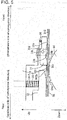
- step S100 when the tail end of the first carrier tape is detected by first sensor 65 which serves as the detection sensor (step S100), and the leading end of the following second carrier tape is subsequently detected by first sensor 65 (step S102), in the next step S104, the sprocket which engages with the second carrier tape is rotated rapidly by a predetermined amount, such that the leading end of the second carrier tape is fed to a point before engaging with the sprocket.
- step S106 a meshing operation which causes the sprocket to mesh with engagement holes 901b of the second carrier tape is performed, the sprocket meshes with engagement holes 901b of the second carrier tape, and the sprocket is positioned at an origin point.
- step S108 the sprocket is rotated by a fixed amount such that the first component is supplied to component supply position 21a.
- the center position of the first component which is stored in storage section 901a of the second carrier tape should be positioned to the defined target position of component supply position 21a; however, due to the individual differences between carrier tapes 900 or the like, a case in which the center position of the component shifts in relation to the target position can occur.
- step S110 moving body 45 is moved, board camera 46 is positioned in a position above component supply position 21a, the first component is imaged by board camera 46, and the center position of the component is identified using image processing. Accordingly, the shift amount ( ⁇ X and ⁇ Y) of the center position of the component in relation to the target position is acquired and stored in the memory of control device 200. In this case, it is possible to move moving body 45 such that the board camera 46 is positioned above component supply position 21a in advance in the time before step S108.
- step S112 moving body 45 is moved based on the offset amount between the center of board camera 46 and the center of the suction nozzle, and moving body 45 is subjected to positional correction control by the positional shift amount ( ⁇ X and ⁇ Y) which is stored in the memory of control device 200. Accordingly, the center of the first component is positioned in a position which matches the target position.
- the suction nozzle is lowered and the suction nozzle picks up the first component.
- the suction nozzle reliably picks up the component at the center of the component.
- the component picked up by the suction nozzle is mounted to a predetermined position of printed circuit board B.
- identification means for imaging the component using board camera 46 and identifying the center position of the component before picking up the first component after switching from the first carrier tape to the second carrier tape is configured, and according to step S112 described above, correction control means for subjecting moving body 45 to positional correction based on the identification carried out by the identification means (step S110) is configured.
- the component is imaged by the board camera 46, the center position of the component is identified, and moving body 45 is subjected to positional correction before picking up the first component after switching from the first carrier tape to the second carrier tape, it is possible to correct the positional shifting caused by individual differences between carrier tapes 900 and the like.
- detection sensor (first sensor) 65 which detects the switching from the first carrier tape to the second carrier tape is provided and an imaging start command is output to board camera 46 when the second carrier tape is fed by a fixed amount from the position detected by the detection sensor 65, it is possible to automatically position the first component which is stored in the second carrier tape in component supply position 21a using detection sensor 65.
- Fig. 16 illustrates an alternative embodiment of the present invention, and although the center position is identified using board camera 46 only for the first component after switching from the first carrier tape to the second carrier tape in the embodiment described above, in the alternative embodiment, the center position of the component is identified a further one or multiple times part way through the supplying of the components (for example, at a midway position) by a single carrier tape 900.
- step S200 it is determined whether the component is the first component after switching from the first carrier tape to the second carrier tape, and, when the determination result is YES, according to the subsequent step S202, image processing of the component which is supplied to the component supply position 21a is performed and the positional shift amount is acquired and stored in the memory of control device 200.
- the process transitions to step S204, and in the same step S204, it is determined whether the component is the component which is stored in the middle position part way down the carrier tape 900, and, when the determination result is YES, according to step S202, image processing of the component which is supplied to component supply position 21a is performed and the positional shift amount is acquired and stored in the memory of control device 200.
- step S206 moving body 45 is subjected to positional correction control.
- whether the component is the component which is stored in the predetermined position in the middle of carrier tape 900 can be determined according to the remaining amount of components of the carrier tape 900 reaching a set number, or, the number of components which are stored in the carrier tape 900 which are mounted to the printed circuit board B reaching a set number, and, based thereon, the imaging start command may be output to board camera 46.
- the suction nozzle it is possible for the suction nozzle to accurately pick up the component which is supplied to the component supply position 21a at the center of the component regardless of fluctuations in the load of pulling out carrier tape 900 caused by changes in the remaining amount of components of carrier tape 900, and further, the cycle time is not increased in comparison to a case in which the component to be picked up is image processed every time.
- feeder 21 is not particularly limited, and any configuration may be adopted as long as feeder 21 is capable of continuously feeding the first carrier tape and the second carrier tape to component supply position 21a without splicing, such as a configuration without providing sprockets.
- a component mounting device is suitable for use as a device which is provided with a feeder capable of continuously feeding a first carrier tape and a second carrier tape to a component supply position without splicing.
Landscapes
- Engineering & Computer Science (AREA)
- Manufacturing & Machinery (AREA)
- Microelectronics & Electronic Packaging (AREA)
- Operations Research (AREA)
- Supply And Installment Of Electrical Components (AREA)
Description
- The present invention relates to a component mounting device which is provided with a feeder capable of continuously feeding a first carrier tape and a second carrier tape to a component supply position without splicing.
- In component mounting devices, multiple feeders are set in a component supply section, and carrier tape is fed by the feeders such that multiple components which are stored in the carrier tape are continuously fed to a component supply position. In this type of component mounting device, in order for a suction nozzle to accurately pick up a component which is supplied to the component supply position, it is necessary to accurately position the component to be supplied to the component supply position at a target position.
- In recent years, as described in PTL 1 for example, feeders capable of continuously feeding a first carrier tape and a second carrier tape to a component supply position without splicing have been developed; in such feeders, when supplying components using the first carrier tape is completed, supplying is switched to the second carrier tape, thus it is possible to continue supplying components.
- PTL 1:
JP-A-2011-171664 - However, when the carrier tape is switched from the first carrier tape to the second carrier tape, due to individual differences between the carrier tapes and so on, the position of the component being fed by the second carrier tape may be shifted slightly in relation to the target position. Therefore, there are cases in which, although it was possible for the suction nozzle to pick up a component at the center position thereof for a component fed by the first carrier tape, it is not possible to pick up a component at the center position thereof after switching to the second carrier tape.
- In this case, although it is possible to improve the pickup accuracy of the components if the components which are supplied to the component supply position are image processed every time before pickup, a new problem arises in that the cycle time is increased due to the image processing, thus reducing the component mounting efficiency.
- The present invention was made to solve the problems described above, and an object thereof is to provide a component mounting device capable of improving the pickup accuracy of components without lengthening cycle time.
- In order to solve the problems described above, the invention according to claim 1 is characterized by a component mounting device which includes a feeder which is detachably mounted to a base and is capable of continuously feeding a first carrier tape and a second carrier tape to a component supply position without splicing, a moving body capable of moving in an XY plane in relation to the base, a component mounting head which is supported by the moving body and holds a suction nozzle which picks up a component which is supplied to the component supply position, an imaging device which is supported by the moving body and images the component which is supplied to the component supply position, identification means that images a component which is the first component after switching from the first carrier tape to the second carrier tape using the imaging device and identifying a center position of the component before picking up the component, and correction control means that subjects the moving body to positional correction based on the identification performed by the identification means such that the suction nozzle picks up the component at the center position of the component.
- The invention according to claim 2 is the component mounting device according to claim 1, further including a detection sensor which detects switching from the first carrier tape to the second carrier tape, in which an imaging start command is output to the imaging device when the second carrier tape has been fed by a fixed amount from the switching position detected by the detection sensor.
- The invention according to claim 3 is the component mounting device according to claim 1 or claim 2, in which imaging of the component by the imaging device is performed at least one time at an intermediate position of the second carrier tape in addition to before picking up the first component after switching from the first carrier tape to the second carrier tape.
- According to the invention according to claim 1, since imaging of the component by the imaging device, identification of the center position of the component, and positional correction of the moving body are performed before picking up the first component after switching from the first carrier tape to the second carrier tape such that the component is picked up at the center position of the component, it is possible to correct the positional shifting caused by individual differences between the carrier tapes, thus it becomes possible for the suction nozzle to accurately pick up the component at the center position of the component. Accordingly, it is possible to reduce pickup errors without significantly increasing the cycle time.
- According to the invention according to claim 2, since an imaging start command is output to the imaging device when the second carrier tape has been fed by a fixed amount from the switching position detected by the detection sensor which detects the switching from the first carrier tape to the second carrier tape, it is possible to automatically position the first component which is stored in the second carrier tape in the component supply position using the detection sensor.
- According to the invention according to claim 3, since imaging of the component by the imaging device is performed at least one time at an intermediate position of the second carrier tape in addition to before picking up the first component after switching from the first carrier tape to the second carrier tape, even if there is variation in the load of pulling out the carrier tape caused by differences in the remaining amount of components, it is possible for the suction nozzle to accurately pick up the component at the center position of the component regardless of positional shifting or the like caused by the variation in load.
-
- [
Fig. 1] Fig. 1 is an overall plan view of a component mounting device illustrating an embodiment of the present invention. - [
Fig. 2] Fig. 2 is a top view of a carrier tape. - [
Fig. 3] Fig. 3 is an A-A sectional diagram of the carrier tape illustrated inFig. 2 . - [
Fig. 4] Fig. 4 is a cutaway side view of a feeder. - [
Fig. 5] Fig. 5 is a cutaway side view representing an insertion portion of the feeder. - [
Fig. 6] Fig. 6 is a cutaway side view representing an insertion portion of the feeder. - [
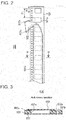
Fig. 7] Fig. 7 is a perspective diagram of a non-splicing feeder to which a tape peeling unit is attached. - [
Fig. 8] Fig. 8 is a perspective diagram illustrating the tape peeling unit in detail. - [
Fig. 9] Fig. 9 is a side view of the tape peeling unit. - [
Fig. 10] Fig. 10 is a cross-sectional diagram taken along the B-B line ofFig. 9 . - [
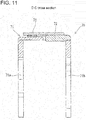
Fig. 11] Fig. 11 is a cross-sectional diagram taken along the C-C line ofFig. 9 . - [
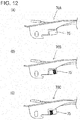
Fig. 12] Fig. 12 is a diagram illustrating multiple types of tape peeling units. - [
Fig. 13] Fig. 13 is a diagram illustrating the position of the cutting edge of multiple types of cutter members. - [
Fig. 14] Fig. 14 is a diagram illustrating a state in which cover tape is folded over by the tape peeling unit. - [
Fig. 15] Fig. 15 is a flowchart illustrating a procedure to perform image processing on a component which is supplied to a component supply position. - [
Fig. 16] Fig. 16 is a flowchart illustrating an alternative example ofFig. 15 . - Hereinafter, description will be given of
component mounting device 100 which is provided withfeeders 21 of the present embodiment usingfig. 1 . In the description, a conveyance direction of a printed circuit board will be referred to as an X-axis direction, a direction perpendicular to the X-axis direction in a horizontal plane will be referred to as a Y-axis direction, and a direction which is perpendicular to the X-axis direction and the Y-axis direction will be referred to as a Z-axis direction. - Note that, hereinafter, to facilitate description, in order to distinguish between carrier tape which is being fed and carrier tape which is standing by, there are cases in which the former is referred to as a first carrier tape and the latter is referred to as a second carrier tape. In these cases, since the second carrier tape becomes the first carrier tape after all of the components which are stored in the first carrier tape are used, the terms first carrier tape and second carrier tape do not indicate a specific carrier tape.
- According to the present embodiment,
component mounting device 100 includesboard conveyance device 10,component supply section 20,component mounting device 40,reel holding section 50, andcontrol device 200 which controls these. -
Component supply section 20 is formed frommultiple slots 20a andmultiple feeders 21 which are detachably mounted to each of theslots 20a.Slots 20a are provided incomponent supply section 20 lined up in parallel in the X-axis direction. - Reel holding
section 50 holds, in an exchangeable manner,first reel 810 andsecond reel 820 on whichcarrier tapes 900 are wound.First reel 810 andsecond reel 820 are arranged adjacent to each other in the Y direction, and multiple of the reels are arranged in the X direction corresponding to each of thefeeders 21. -
Carrier tape 900 stores many components such as electronic components in a row. As shown infig. 2 and fig. 3 ,carrier tape 900 is formed ofbase tape 901,cover tape 902, andbottom tape 903.Base tape 901 is formed of a flexible material such as a paper material or a resin.Storage sections 901a, which are cavities, are formed as through-holes in a center portion ofbase tape 901 in the width direction at a fixed interval in the length direction. Components are stored instorage sections 901a. Engagement holes 901b are formed as through-holes in a side portion of thebase tape 901 at a fixed interval in the length direction. - Both side portions of
cover tape 902 are adhered to both side portions of the top surface ofbase tape 901 using an adhesive 902a (refer tofig. 3 ).Cover tape 902 is formed of a transparent polymer film. - As illustrated in
fig. 3 ,bottom tape 903 is adhered to the bottom surface ofbase tape 901. Components which are stored instorage sections 901a are prevented from falling out bybottom tape 903.Bottom tape 903 is formed of a paper material, a polymer film or the like and is transparent or semi-transparent. -
Carrier tape 900 which is wound onfirst reels 810 andsecond reels 820 is inserted into each of the correspondingfeeders 21. Carrier tape (first carrier tape) 900 which is wound on one of the reels 810 (820) is sequentially supplied tocomponent supply position 21a which is provided on a tip portion offeeder 21 byfeeder 21. Accordingly, components held incarrier tape 900 are supplied tocomponent supply position 21a. Although carrier tape (second carrier tape) 900 which is wound on the other reel 820 (810) is inserted intofeeder 21, thiscarrier tape 900 stands by without being supplied byfeeder 21. Detailed description offeeder 21 will be given later. - In
board conveyance device 10, a pair ofguide rails base 41 ofcomponent mounting device 40. Also, a pair of conveyor belts which support and convey a printed circuit board B which is guided by both of theguide rails board conveyance device 10. Also, a clamp device which holds up and clamps the printed circuit board B which is conveyed to a predetermined position and which is omitted from the drawings is provided inboard conveyance device 10. - Printed circuit board B on which components are mounted is conveyed in the X-axis direction to a component mounting position by the conveyor belts while being guided by
guide rails board conveyance device 10. Printed circuit board B which is conveyed to the component mounting position is positioned and clamped in the component mounting position by the clamp device. - As illustrated in
fig. 1 ,component mounting device 40 includesguide rail 42, Y-axis slide 43,X-axis slide 45, andcomponent mounting head 48 which holds a suction nozzle which is not depicted in the drawings. The movement of Y-axis slide 43 and X-axis slide 45 in the Y-axis direction and the X-axis direction is controlled by a Y-axis servo motor and an X-axis servo motor which are omitted from the drawings. - A Y-axis robot is formed by
guide rail 42 and Y-axis slide 43.Guide rail 42 is mounted in the Y-axis direction above thebase 41 and is arranged to be aboveboard conveyance device 10. Y-axis slide 43 is provided to be capable of moving in the Y-axis direction alongguide rail 42. Y-axis slide 43 is moved in the Y-axis direction via a ball screw mechanism by the Y-axis servo motor which is omitted from the drawings. - An X-axis robot is formed by
X-axis slide 45.X-axis slide 45 is provided to be capable of moving in the X-axis direction on Y-axis slide 43. The X-axis servo motor which is omitted from the drawings is provided in Y-axis slide 43.X-axis slide 45 is moved in the X-axis direction via a ball screw mechanism by the X-axis servo motor.X-axis slide 45 forms a moving body capable of moving in the X-axis direction and the Y-axis direction. -
Component mounting head 48 is provided onX-axis slide 45.Component mounting head 48 holds the suction nozzle (not illustrated in the drawings) in a detachable manner. The suction nozzle picks up a component which is supplied tocomponent supply position 21a and mounts the component on the printed circuit board B which is positioned in the component mounting position byboard conveyance device 10. -
Board camera 46 which serves as an imaging device is attached ontoX-axis slide 45, andboard camera 46 images fiducial marks which are provided on the printed circuit board B which is positioned in a board mounting position, or a component or the like which is supplied to thecomponent supply position 21a, from above, and acquires board position fiducial information, component position information, and the like. - Component camera 47 capable of imaging a component which has been picked up by the suction nozzle from beneath is provided on
base 41. - Hereinafter, description will be given of
feeder 21 of the present embodiment usingfigs. 4 to 6 . Note that, in the description hereinafter, the term "conveyance direction" indicates the conveyance direction ofcarrier tape 900. Infigs. 4 to 6 , the right side of the paper surface is set to the front (the downstream side in the conveyance direction) and the left side of the paper surface is set to the rear (the upstream side in the conveyance direction). Infigs. 4 to 6 , upward on the paper surface is set to upward, and downward on the paper surface is set to downward. -
Feeder 21 is formed mainly ofmain body 21b,first servo motor 22,second servo motor 23,first gear 24,second gear 25,third gear 26,fourth gear 27, liftingprevention member 28,torsion spring 29,stopper member 31, upstreamside retaining member 32, downstreamside retaining member 33,first sprocket 61,second sprocket 62,third sprocket 63,fourth sprocket 64,rail 38,control section 39, andtape peeling unit 70. -
Feeder 21 is mounted by being inserted intoslot 20a from the front.Main body 21b is a flat box shape. Note that,figs. 4 to 6 are diagrams with a side wall ofmain body 21b removed to show the internal structure offeeder 21. -
Rail 38 is provided frominsertion section 21d at the rear section ofmain body 21b to supplyposition 21a at the front portion ofmain body 21b. The top surface ofrail 38 forms the conveying path ofcarrier tape 900.Front section 38a ofrail 38 is formed horizontally. In the present embodiment,rail 38 is inclined to gradually increase in height from the rear section to beforefront section 38a. Note that, although not depicted in the drawings, guide members which are separated by a dimension which is slightly greater than the width dimension ofcarrier tape 900 are provided on both sides ofrail 38. - Each of
first sprocket 61 andsecond sprocket 62 is provided, to be capable of rotating, from the front toward the rear (from the downstream side to the upstream side in the conveyance direction) inmain body 21b beneathfront section 38a ofrail 38, that is, in positions adjacent to thesupply position 21a ofmain body 21b. Each ofthird sprocket 63 andfourth sprocket 64 is provided, to be capable of rotating, from the front toward the rear inmain body 21b beneath the rear section ofrail 38. First engagingprotrusions 61a, second engagingprotrusions 62a, and third engaging protrusions 63a are formed at a fixed angle on the outer circumferences offirst sprocket 61,second sprocket 62, andthird sprocket 63, respectively. Fourth engagingprotrusions 64a are formed at a fixed angle on a portion of the outer circumference offourth sprocket 64. Each of the engagingprotrusions 61a to 64a engages withengagement holes 901b ofcarrier tape 900. -
First sprocket gear 61b,second sprocket gear 62b,third sprocket gear 63b, and fourth sprocket gear 64b are formed closer to the inside than the outer circumference of thefirst sprocket 61 to thefourth sprocket 64, respectively. Note that,window hole 38b (refer tofig. 5 ) is provided above each of thesprockets 61 to 64 ofrail 38. Each of the engagingprotrusions 61a to 64a protrudes from the top ofrail 38 throughwindow holes 38b. -
First servo motor 22 is a servo motor which rotates thefirst sprocket 61 and thesecond sprocket 62.First drive gear 22b is provided onrotating shaft 22a of thefirst servo motor 22.First gear 24 is rotatably provided onmain body 21b beneathfirst sprocket 61 andsecond sprocket 62. First outsidegear 24a which meshes withfirst drive gear 22b is formed on the outer circumference offirst gear 24. First insidegear 24b is formed closer to the inside than the outer circumference offirst gear 24. -
Second gear 25 is rotatably provided onmain body 21b betweenfirst sprocket 61 andsecond sprocket 62, andfirst gear 24.Second gear 25 meshes withfirst sprocket gear 61b,second sprocket gear 62b, and first insidegear 24b. According to this configuration, the rotation speed offirst servo motor 22 is reduced and transmitted tofirst sprocket 61 andsecond sprocket 62, and,first sprocket 61 andsecond sprocket 62 rotate in synchronization. -
Second servo motor 23 is a servo motor which rotatesthird sprocket 63 andfourth sprocket 64.Second drive gear 23b is provided onrotating shaft 23a ofsecond servo motor 23.Third gear 26 is rotatably provided onmain body 21b beneaththird sprocket 63 andfourth sprocket 64. Third outsidegear 26a which meshes withsecond drive gear 23b is formed on the outer circumference ofthird gear 26. Third insidegear 26b is formed closer to the inside than the outer circumference ofthird gear 25. -
Fourth gear 27 is rotatably provided onmain body 21b betweenthird sprocket 63 andfourth sprocket 64, andthird gear 26.Fourth gear 27 meshes withthird sprocket gear 63b, fourth sprocket gear 64b, and thirdinside gear 26b. According to this configuration, the rotation speed ofsecond servo motor 23 is reduced and transmitted tothird sprocket 63 andfourth sprocket 64, and,third sprocket 63 andfourth sprocket 64 rotate in synchronization. - Downstream
side retaining member 33 is block-shaped and is provided oninsertion section 21d ofmain body 21b above the rear section ofrail 38. Downstreamside retaining member 33 is attached to first support member 30-1 and second support member 30-2, which are attached tomain body 21b, via shaft 34-1 so as to be capable of moving in the vertical direction. Coil spring 35-1 which biases downstreamside retaining member 33 downward is attached to shaft 34-1. Retainingsection 33d which abutsrail 38 onthird sprocket 63 is formed in front of the downstreamside retaining member 33. According to this configuration, retainingsection 33d moves toward and away from therail 38. As illustrated infig. 5 , penetratingsection 33b is formed as a cutout on the bottom portion of the rear end of retainingsection 33d. - Upstream
side retaining member 32 is block-shaped and is provided along the top surface of the rear section ofrail 38. Upstreamside retaining member 32 is attached beneath the rear section of downstreamside retaining member 33 via shaft 34-2 to be capable of moving in the vertical direction. Upstreamside retaining member 32 is adjacent to the rear of retainingsection 33d. Coil spring 35-2 which biases upstreamside retaining member 32 downward is attached to shaft 34-2. According to this configuration, upstreamside retaining member 32 moves toward and away fromrail 38. Insertion recessedsection 32a is formed as a cutout on the bottom portion of the rear end of upstreamside retaining member 32. - As illustrated in
fig. 5 ,stopper member 31 is block-shaped and is provided adjacent on the downstream side of upstreamside retaining member 32.Stopper member 31 is capable of rocking due toshaft support section 31b which is formed in a middle portion ofstopper member 31 being axially supported by downstreamside retaining member 33. Abuttingsection 31a which is formed to protrude downward is formed on the bottom portion ofstopper member 31 which is closer to the front than theshaft support portion 31b. The rear end of the bottom section ofstopper member 31 is stoppingsection 31c. -
Spring 36 whichbiases stopper member 31 in a direction in which abuttingsection 31a approachesrail 38 is attached to downstreamside retaining member 33. As illustrated infig. 5 , in relation to the conveyance direction, the apex section offourth sprocket 64 is positioned between the front end of downstreamside retaining member 33 and the rear end ofstopper member 31. - As illustrated in
fig. 4 , liftingprevention member 28 is plate-shaped and is provided along the top ofrail 38 between thethird sprocket 63 and thesecond sprocket 62.Shaft support portion 28a is formed on the front end of liftingprevention member 28, andshaft support portion 28a is axially supported onshaft portion 21c which is provided inmain body 21b, and, liftingprevention member 28 is attached tomain body 21b to be capable of rocking.Guide portion 28b which is bent upward is formed on the rear end of liftingprevention member 28.Torsion spring 29 is attached tomain body 21b above liftingprevention member 28 and biases liftingprevention member 28 downward. The bottom surface of liftingprevention member 28 comes into close contact with the top surface ofrail 38 due totorsion spring 29. - Note that,
space 38c is formed aboverail 38 betweensecond sprocket 62 andthird sprocket 63. -
Control section 39controls feeder 21 and controls the rotation offirst servo motor 22 andsecond servo motor 23.Control section 39 includes a microprocessor and a driver which supplies the drive currents toservo motors -
First sensor 65 which detects the presence or absence ofcarrier tape 900 and outputs that detection signal to controlsection 39 is provided inmain body 21b on the downstream side ofthird sprocket 63.First sensor 65 is a sensor which detects a boundary portion betweenconveyance tape 910 andstandby tape 920 which are described later.Second sensor 66 which detects the presence or absence ofcarrier tape 900 and outputs that detection signal to controlsection 39 is provided inmain body 21b on the upstream side ofsecond sprocket 62. Description will be given of the role ofsecond sensor 66 later. - Hereinafter, description will be given of operations of
feeder 21. A worker insertscarrier tape 900 between the insertion recessedsection 32a and the rear end ofrail 38 which are illustrated infig. 4 . When this is done, fourth engagingprotrusions 64a engage withengagement holes 901b which are formed in the leading end of the insertedcarrier tape 900, and thecarrier tape 900 is conveyed tothird sprocket 63 byfourth sprocket 64. Since fourth engagingprotrusions 64a are only formed in a portion of the outer circumference offourth sprocket 64, when fourthengaging protrusions 64a engage withengagement holes 901b which are formed in the leading end of the insertedcarrier tape 900,carrier tape 900 moves to thethird sprocket 63 side intermittently. Therefore, sincecarrier tape 900 is not suddenly pulled to thethird sprocket 63 side, this is safe. - The leading end of
carrier tape 900 which is supplied to the downstream side byfourth sprocket 64 enters below retainingsection 33d from penetratingsection 33b. When engagement holes 901b which are formed in the leading portion ofcarrier tape 900 are engaged with third engaging protrusions 63a,carrier tape 900 is conveyed tosecond sprocket 62 bythird sprocket 63. Since third engaging protrusions 63a are formed along the entire circumference of the outer circumference ofthird sprocket 63,carrier tape 900 is conveyed tosecond sprocket 62 side in a short time. Note that,conveyance tape 910 is pushed from above by retainingsection 33d such that the engagement betweenengagement holes 901b and third engaging protrusions 36a is not released. - The leading end of
carrier tape 900 enters beneath liftingprevention member 28 from betweenguide section 28b andrail 38. The leading end ofcarrier tape 900 is suppressed from lifting up fromrail 38 by liftingprevention member 28 and is conveyed tosecond sprocket 62. - When
second sensor 66 detects the leading end ofcarrier tape 900 which is conveyed thereto bythird sprocket 63,first servo motor 22 andsecond servo motor 23 intermittently rotatesprockets 61 to 64 by component pitch P1 (illustrated inFig. 2 ) . When engagement holes 901b which are formed on the leading end section ofcarrier tape 900 engage with secondengaging protrusions 62a,carrier tape 900 is fed to tape peelingunit 70 bysecond sprocket 62 andcover tape 902 is peeled fromcarrier tape 900 bytape peeling unit 70. When engagement holes 901b which are formed on the leading end section ofcarrier tape 900 engage with first engagingprotrusions 61a, components which are stored incarrier tape 900 are sequentially positioned insupply position 21a so as to be supplied byfirst sprocket 61. - While
conveyance tape 910 which iscarrier tape 900 being conveyed is being conveyed by thefeeder 21, as illustrated infig. 5 ,conveyance tape 910presses abutting section 31a,stopper member 31c rocks in a direction acting against the biasing force ofspring 36 such that stoppingsection 31c approachesrail 38, thus the rear-bottom end ofstopper member 31 contacts the top surface ofconveyance tape 910. - The worker inserts
standby tape 920, which is thecarrier tape 900 that stands by, between insertion recessedsection 32a andconveyance tape 910. When this is done, since the rear-bottom end ofstopper member 31 contacts the top surface ofconveyance tape 910, the tip ofstandby tape 920 abuts stoppingsection 31c ofstopper member 31, conveyance to the downstream ofstandby tape 920 is prevented, andstandby tape 920 stands byabove conveyance tape 910. -
Standby tape 920 is pushed intoconveyance tape 910 by upstreamside retaining member 32. Therefore, lifting of the tip ofstandby tape 920 fromconveyance tape 910 is prevented, and the entering of the tip ofstandby tape 920 between the front end of upstreamside retaining member 32 and the rear end ofstopper member 31 is prevented. - Note that,
conveyance tape 910 is wound onreel 810 which is on the front side.Standby tape 920 is wound onreel 820 which is on the rear side. - As illustrated in
fig. 6 , when the tail end ofconveyance tape 910 is conveyed closer to the downstream side than the leading end ofstandby tape 920,standby tape 920 assumes a state of being onrail 38, andengagement holes 901b which are formed in the leading section ofstandby tape 920 are engaged with fourth engagingprotrusions 64a. The leading end ofcarrier tape 900 which is supplied byfourth sprocket 64 enters below retainingsection 33d from penetratingsection 33b. When engagement holes 901b which are formed in the leading section ofcarrier tape 900 are engaged with third engaging protrusions 63a,carrier tape 900 is conveyed tosecond sprocket 62 bythird sprocket 63 and is conveyed to supplyposition 21a as described above. - When the leading end of
carrier tape 900 which wasstandby tape 920 presses the abuttingportion 31a,stopper member 31 rocks in a direction against the biasing force ofspring 36, such that stoppingportion 31c approaches the top surface ofrail 38, and the rear-bottom end ofstopper member 31 comes into contact with the new conveyance tape 910 (the old standby tape 920). - The worker removes the used
reel 810 for which all of theconveyance tape 910 has been supplied fromreel holding section 50 and causes thereel holding section 50 to hold thereel 820 on whichnew standby tape 920 is wound. The worker sets thenew standby tape 920 by inserting the leading end of thenew standby tape 920 between insertion recessedportion 32a andconveyance tape 910. As described above, since the rear-bottom end ofstopper member 31 contacts thenew conveyance tape 910, the tip of thenew standby tape 920 abuts stoppingportion 31c ofstopper member 31, conveyance to the downstream of thestandby tape 920 is prevented, andstandby tape 920 stands byabove conveyance tape 910. - Next, description will be given of the configuration of
tape peeling unit 70 usingfigs. 7 to 14 . As illustrated infig. 7 , at the tip offeeder 21,tape peeling unit 70 for peelingcover tape 902 ofcarrier tape 900 which is fed to thecomponent supply position 21a is fixed to feedermain body 21b in a detachable manner. - Multiple types of
tape peeling unit 70 are prepared corresponding to the types ofcarrier tapes 900, and atape peeling unit 70 corresponding to the type ofcarrier tape 900 which is mounted infeeder 21 is attached to feedermain body 21b. In the embodiment, as illustrated infig. 12 , three types oftape peeling units - As illustrated in
figs. 8 to 11 ,tape peeling unit 70 includes unitmain body 71 having a U-shaped cross section with a downward facing opening, the front and rear of bothside walls main body 71 are fixed to both side surfaces of feedermain body 21b using a fastening means such as a screw, andcarrier tape 900 is guided between both of theside walls component supply position 21a is formed in a predetermined position inupper wall 71c of unitmain body 71, such that it is possible to remove a component fromstorage section 901a ofcarrier tape 900. - Plate-shaped
cutter member 72, which has acutting edge 72a with a sharp tip which peels thecover tape 902 of thecarrier tape 900, is fixed toupper wall 71c of unitmain body 71 in a position abovecarrier tape 900 so as to cover cutout 71c1. Both edges ofcover tape 902 are adhered to thecarrier tape 900 and cuttingedge 72a ofcutter member 72 is provided in a position corresponding to one edge (the edge at theengagement hole 901b side) ofcover tape 902. Cuttingedge 72a ofcutter member 72 is interposed betweenbase tape 901 and covertape 902 ascarrier tape 900 is fed so as to peel one edge ofcover tape 902 while maintaining the adhered state of the other edge ofcover tape 902. - Here, as illustrated in
fig. 13 , although the multiple types ofcarrier tapes 900 haveengagement holes 901b of the same pitch, the sizes ofstorage sections 901a and the components which are stored therein are different. Therefore, the width dimensions ofcover tapes 902 which coverstorage sections 901a also differ from each other according to the size ofstorage sections 901a, and the position of the one edge (the adherence position) ofcover tape 902 which is peeled by cuttingedge 72a ofcutter member 72 differs for each type ofcarrier tape 900. - With the above configuration, as illustrated in
fig. 13 , cuttingedge 72a ofcutter member 72 is positioned separated from the center ofcarrier tape 900 by an amount d1, d2, or d3 corresponding to one edge ofcover tape 902. In this manner, the cutting edge ofcutter member 72 is positioned in a different position in the width direction of each of thecarrier tapes 900 based on the type of the multiple types oftape peeling units - Also, plate-shaped fold-over
member 73 which erects and folds over one of the edges of peeledcover tape 902 is fixed onupper wall 71c of unitmain body 71 such that a small gap is formed between fold-overmember 73 and the top surface ofcarrier tape 900.Inclined surface 73a which is inclined in the width direction ofcover tape 902 is formed on fold-overmember 73 across a predetermined length along the feeding direction ofcarrier tape 900.Inclined surface 73a of fold-overmember 73 protrudes in the width direction ofcover tape 902 in relation tocutter member 72. - Fold-over
member 73 folds over one of the edges ofcover tape 902 which is peeled by cuttingedge 72a ofcutter member 72 such that the edge ofcover tape 902 is gradually erected byinclined surface 73a, thus opening (exposing) the top surface ofstorage section 901a in which the component which is supplied to thecomponent supply position 21a is stored. As illustrated infig. 14 ,cover tape 902 which is folded over byinclined surface 73a of fold-overmember 73 is forcefully inserted into the gap between fold-overmember 73 and the top surface of carrier tape 900 (base tape 901) such that the open state of the top surface ofstorage section 901a is maintained. - By adopting this configuration, as with conventional art, individual collection mechanisms which fold over and collect
cover tape 902 become unnecessary, and covertape 902 becomes capable of being collected together withbase tape 901 ofcarrier tape 900. Note that, 74 infig. 7 is a guide for collectingcover tape 902 andcarrier tape 900, and is fixed to the tip portion of feedermain body 21b. - In
tape peeling unit 70,identification mark 75 corresponding to the type ofcarrier tape 900 is formed on the inside of one of theside walls 71a of unitmain body 71, andidentification sensor 76 which identifiesidentification mark 75 is attached to the side surface of feedermain body 21b which faces the inside of theside wall 71a. - In the embodiment, for example, as illustrated in
figs. 12 (A) to (C) , codes with black and while coloring are lined up in two rows in the feeding direction ofcarrier tape 900 to formidentification mark 75, andidentification mark 75 is identified using twoidentification sensors identification sensors tape peeling units 70 according to the combinations "white-white", "white-black", and "black-white". -
Tape peeling unit 70 of the configuration described above which matches the type ofcarrier tape 900 to be mounted infeeder 21 is attached to feedermain body 21b by an operator outside of the device. -
Feeder 21 to which tape peeling unit 70 (70A, 70B, or 70C) is attached is set incomponent supply section 20, power is supplied to thefeeder 21 side from the main body side ofcomponent mounting device 100 via communication connector 80 (refer toFig. 7 ), and necessary information such as the feeder ID is transmitted from thefeeder 21 side to the main body side ofcomponent mounting device 100. Accordingly, the information of the component which is fed bycarrier tape 900 which is mounted infeeder 21 is acquired based on the serial ID offeeder 21 and stored incontrol device 200 ofcomponent mounting device 100. At the same time, the information of the type oftape peeling unit 70 which is identified by identification sensor 76 (76a and 76b) which is provided infeeder 21 is stored incontrol device 200 ofcomponent mounting device 100. - Note that,
feeder mark 77 indicating a reference position offeeder 21 is formed on feedermain body 21b. For example,feeder mark 77 is formed on the top surface of the tip offeeder 21, andhole 78 is formed inupper wall 71c and fold-overmember 73 of unitmain body 71 which is attached to the tip portion offeeder 21 such that it is possible to imagefeeder mark 77 from above usingboard camera 46. - When
feeder 21 ofcomponent supply section 20 is set,control device 200 compares the information of the component which is acquired based on the serial ID and the information which is identified by identification sensor 76 (76a and 76b) usingcomparison section 200a ofcontrol device 200, and, when the information does not match, that is, when it is determined that atape peeling unit 70 which does not correspond to the carrier tape (the component) 900 which is fed byfeeder 21 is attached, a warning is issued to the operator and the operator is urged to exchange thetape peeling unit 70. - Note that, in this case, a display section may be provided on the top surface of feeder
main body 21b, and the comparison result obtained bycomparison section 200a may be displayed on this display section. Accordingly, the operator can identify the comparison result using the display content of the display section. - Next, based on
fig. 15 , description will be given of the image processing performed bycontrol device 200 when the carrier tape which supplies the components is switched from a first carrier tape to a second carrier tape. When the carrier tape is switched, in order to correct the individual differences between carrier tapes and shifting of components caused by the meshing of sprockets and the carrier tape, image processing is performed before picking up the first component of the second carrier tape, and the suction nozzle can accurately pick up the component at the center of the component regardless of the individual differences between the carrier tapes and the like. - In
fig. 15 , when the tail end of the first carrier tape is detected byfirst sensor 65 which serves as the detection sensor (step S100), and the leading end of the following second carrier tape is subsequently detected by first sensor 65 (step S102), in the next step S104, the sprocket which engages with the second carrier tape is rotated rapidly by a predetermined amount, such that the leading end of the second carrier tape is fed to a point before engaging with the sprocket. - Next, in step S106, a meshing operation which causes the sprocket to mesh with
engagement holes 901b of the second carrier tape is performed, the sprocket meshes withengagement holes 901b of the second carrier tape, and the sprocket is positioned at an origin point. Next, in step S108, the sprocket is rotated by a fixed amount such that the first component is supplied tocomponent supply position 21a. - At this time, due to the sprocket being rotated by a fixed amount from the origin point position, the center position of the first component which is stored in
storage section 901a of the second carrier tape should be positioned to the defined target position ofcomponent supply position 21a; however, due to the individual differences betweencarrier tapes 900 or the like, a case in which the center position of the component shifts in relation to the target position can occur. - In step S110, moving
body 45 is moved,board camera 46 is positioned in a position abovecomponent supply position 21a, the first component is imaged byboard camera 46, and the center position of the component is identified using image processing. Accordingly, the shift amount (ΔX and ΔY) of the center position of the component in relation to the target position is acquired and stored in the memory ofcontrol device 200. In this case, it is possible to move movingbody 45 such that theboard camera 46 is positioned abovecomponent supply position 21a in advance in the time before step S108. - In step S112, moving
body 45 is moved based on the offset amount between the center ofboard camera 46 and the center of the suction nozzle, and movingbody 45 is subjected to positional correction control by the positional shift amount (ΔX and ΔY) which is stored in the memory ofcontrol device 200. Accordingly, the center of the first component is positioned in a position which matches the target position. - In this state, the suction nozzle is lowered and the suction nozzle picks up the first component. At this time, due to the correction of the positional shift amount (ΔX and ΔY) described above, the suction nozzle reliably picks up the component at the center of the component. Subsequently, the component picked up by the suction nozzle is mounted to a predetermined position of printed circuit board B.
- According to step S110 described above, identification means for imaging the component using
board camera 46 and identifying the center position of the component before picking up the first component after switching from the first carrier tape to the second carrier tape is configured, and according to step S112 described above, correction control means for subjecting movingbody 45 to positional correction based on the identification carried out by the identification means (step S110) is configured. - Note that, since it is possible to resolve the individual differences between the first carrier tape and the second carrier tape by subjecting the center of the first component to positional correction in relation to
component supply position 21a, it is possible to substantially accurately supply the second component onward tocomponent supply position 21a based on the feeding pitch ofcarrier tape 900 usingsprockets - In this manner, since the center position of the component is identified by performing image processing before picking up the first component when
carrier tape 900 is switched, even if thecarrier tape 900 is switched, it is possible for the suction nozzle to accurately pick up the component at the center of the component. Accordingly, it becomes possible to reduce pickup errors of the components regardless of the individual differences betweencarrier tapes 900. - According to the embodiment described above, since the component is imaged by the
board camera 46, the center position of the component is identified, and movingbody 45 is subjected to positional correction before picking up the first component after switching from the first carrier tape to the second carrier tape, it is possible to correct the positional shifting caused by individual differences betweencarrier tapes 900 and the like. - Accordingly, since it becomes possible for the suction nozzle to accurately pick up the component at the center of the component regardless of the individual differences between
carrier tapes 900 and the like, it is possible to reduce pickup errors without significantly increasing the cycle time. - According to the embodiment described above, since detection sensor (first sensor) 65 which detects the switching from the first carrier tape to the second carrier tape is provided and an imaging start command is output to board
camera 46 when the second carrier tape is fed by a fixed amount from the position detected by thedetection sensor 65, it is possible to automatically position the first component which is stored in the second carrier tape incomponent supply position 21a usingdetection sensor 65. -
Fig. 16 illustrates an alternative embodiment of the present invention, and although the center position is identified usingboard camera 46 only for the first component after switching from the first carrier tape to the second carrier tape in the embodiment described above, in the alternative embodiment, the center position of the component is identified a further one or multiple times part way through the supplying of the components (for example, at a midway position) by asingle carrier tape 900. - This is because, the load of pulling out
carrier tape 900 fluctuates due to changes in the remaining amount of the components which are stored in thecarrier tape 900, and shifting arises in the position of the components which are supplied tocomponent supply position 21a due to the fluctuation in the load. - In
fig. 16 , according to step S200, it is determined whether the component is the first component after switching from the first carrier tape to the second carrier tape, and, when the determination result is YES, according to the subsequent step S202, image processing of the component which is supplied to thecomponent supply position 21a is performed and the positional shift amount is acquired and stored in the memory ofcontrol device 200. When the component is not the first component, the process transitions to step S204, and in the same step S204, it is determined whether the component is the component which is stored in the middle position part way down thecarrier tape 900, and, when the determination result is YES, according to step S202, image processing of the component which is supplied tocomponent supply position 21a is performed and the positional shift amount is acquired and stored in the memory ofcontrol device 200. Subsequently, in a similar manner to the embodiment described above, in step S206, movingbody 45 is subjected to positional correction control. - Note that, whether the component is the component which is stored in the predetermined position in the middle of
carrier tape 900 can be determined according to the remaining amount of components of thecarrier tape 900 reaching a set number, or, the number of components which are stored in thecarrier tape 900 which are mounted to the printed circuit board B reaching a set number, and, based thereon, the imaging start command may be output to boardcamera 46. - According to the alternative embodiment described above, it is possible for the suction nozzle to accurately pick up the component which is supplied to the
component supply position 21a at the center of the component regardless of fluctuations in the load of pulling outcarrier tape 900 caused by changes in the remaining amount of components ofcarrier tape 900, and further, the cycle time is not increased in comparison to a case in which the component to be picked up is image processed every time. - In the embodiments described above, description is given of an example in which feeding the first carrier tape and the second carrier tape to
component supply position 21a is performed continuously without splicing by usingfeeder 21 which is provided with sprocket 61 (62) which feeds the component which is stored in the first carrier tape tocomponent supply position 21a by engaging with the first carrier tape, and sprocket 63 (64) which engages the second carrier tape which is standing by and feeds the second carrier tape to a position which engages with thesprocket 61. However, for the present invention, the configuration offeeder 21 is not particularly limited, and any configuration may be adopted as long asfeeder 21 is capable of continuously feeding the first carrier tape and the second carrier tape tocomponent supply position 21a without splicing, such as a configuration without providing sprockets. - In this manner, the invention is not limited to the configuration described in the embodiments described above, and various embodiments may be adopted within a scope that does not depart from the gist of the present invention described in the claims.
- A component mounting device according to the present invention is suitable for use as a device which is provided with a feeder capable of continuously feeding a first carrier tape and a second carrier tape to a component supply position without splicing.
- 100 ... component mounting device, 10 ... board conveyance device, 20 ... component supply section, 21 ... feeder, 21a ... component supply position, 40 ... component mounting device, 41 ... base, 45 ... moving body, 46 ... imaging device (board camera), 48 ... component mounting head, 65 ... detection sensor (first sensor), step S110 ... identification means, step S112 ... correction control means, 900 ... carrier tape
Claims (3)
- A component mounting device, comprising:a feeder which is detachably mounted to a base and is capable of continuously feeding a first carrier tape and a second carrier tape to a component supply position without splicing;a moving body capable of moving in an XY plane in relation to the base;a component mounting head which is supported by the moving body and holds a suction nozzle which picks up a component which is supplied to the component supply position;an imaging device which is supported by the moving body and images the component which is supplied to the component supply position;identification means that images a component which is the first component after switching from the first carrier tape to the second carrier tape using the imaging device and identifying a center position of the component before picking up the component; andcorrection control means that subjects the moving body to positional correction based on the identification performed by the identification means such that the suction nozzle picks up the component at the center position of the component.
- The component mounting device according to claim 1, further comprising:a detection sensor which detects switching from the first carrier tape to the second carrier tape,wherein an imaging start command is output to the imaging device when the second carrier tape has been fed by a fixed amount from the switching position detected by the detection sensor.
- The component mounting device according to claim 1 or claim 2,
wherein imaging of the component by the imaging device is performed at least one time at an intermediate position of the second carrier tape in addition to before picking up the first component after switching from the first carrier tape to the second carrier tape.
Applications Claiming Priority (1)
| Application Number | Priority Date | Filing Date | Title |
|---|---|---|---|
| PCT/JP2013/072782 WO2015029123A1 (en) | 2013-08-26 | 2013-08-26 | Component mounting device |
Publications (3)
| Publication Number | Publication Date |
|---|---|
| EP3041337A1 true EP3041337A1 (en) | 2016-07-06 |
| EP3041337A4 EP3041337A4 (en) | 2017-05-03 |
| EP3041337B1 EP3041337B1 (en) | 2020-07-22 |
Family
ID=52585742
Family Applications (1)
| Application Number | Title | Priority Date | Filing Date |
|---|---|---|---|
| EP13892745.4A Active EP3041337B1 (en) | 2013-08-26 | 2013-08-26 | Component mounting device |
Country Status (5)
| Country | Link |
|---|---|
| US (1) | US10165717B2 (en) |
| EP (1) | EP3041337B1 (en) |
| JP (1) | JP6363606B2 (en) |
| CN (1) | CN105474773B (en) |
| WO (1) | WO2015029123A1 (en) |
Cited By (4)
| Publication number | Priority date | Publication date | Assignee | Title |
|---|---|---|---|---|
| WO2019016604A1 (en) * | 2017-07-17 | 2019-01-24 | Asm Assembly Systems Gmbh & Co.Kg | Measuring of components before pickup by means of a placement head |
| CN110476495A (en) * | 2017-04-05 | 2019-11-19 | 株式会社富士 | Loader |
| CN112567903A (en) * | 2018-08-24 | 2021-03-26 | 株式会社富士 | Component mounting machine and component pickup method |
| CN115245067A (en) * | 2020-03-10 | 2022-10-25 | 株式会社富士 | With guide management system |
Families Citing this family (20)
| Publication number | Priority date | Publication date | Assignee | Title |
|---|---|---|---|---|
| US10342168B2 (en) * | 2015-06-18 | 2019-07-02 | Fuji Corporation | Feeder |
| CN108293318B (en) * | 2015-11-30 | 2020-06-30 | 株式会社富士 | Power control device and power control method of component supply device |
| US10321620B2 (en) * | 2015-12-25 | 2019-06-11 | Panasonic Intellectual Property Management Co., Ltd. | Component supplying device and component supplying method |
| JP2017157653A (en) * | 2016-03-01 | 2017-09-07 | パナソニックIpマネジメント株式会社 | Component mounting apparatus and component mounting method |
| CN105555118B (en) * | 2016-03-15 | 2018-08-28 | 成都秦川物联网科技股份有限公司 | SMT surface mount elements webbing winding method and device |
| JP6807386B2 (en) * | 2016-06-08 | 2021-01-06 | 株式会社Fuji | Component mounting system |
| JP6956431B2 (en) * | 2016-07-15 | 2021-11-02 | 株式会社Fuji | Feeder device |
| JP6780898B2 (en) * | 2016-07-15 | 2020-11-04 | 株式会社Fuji | Feeder device |
| CN109691256B (en) * | 2016-09-13 | 2022-03-04 | 环球仪器公司 | Feeder system, pick and place machine and method |
| CN108860717B (en) * | 2017-05-16 | 2021-08-31 | 太阳诱电株式会社 | Electronic component insertion apparatus and method, electronic component storage tape manufacturing apparatus and method |
| JP6974477B2 (en) * | 2017-08-25 | 2021-12-01 | 株式会社Fuji | Tape feeder control system |
| JP7257630B2 (en) * | 2017-09-25 | 2023-04-14 | パナソニックIpマネジメント株式会社 | PARTS SUPPLY DEVICE, PARTS SUPPLY MANAGEMENT SYSTEM AND PARTS SUPPLY WORK SUPPORT METHOD |
| JP7012210B2 (en) * | 2017-09-25 | 2022-01-28 | パナソニックIpマネジメント株式会社 | Parts supply management system and parts supply management method |
| EP3829284B1 (en) * | 2018-07-24 | 2023-11-15 | Fuji Corporation | Information processing device, work system, and determination method |
| JP7164923B2 (en) * | 2020-10-12 | 2022-11-02 | 株式会社Fuji | Mounting machine |
| JP7161643B2 (en) * | 2020-11-18 | 2022-10-26 | 株式会社Fuji | tape feeder |
| JP7145191B2 (en) * | 2020-11-18 | 2022-09-30 | 株式会社Fuji | tape feeder |
| JP7648387B2 (en) * | 2021-01-12 | 2025-03-18 | 株式会社Fuji | Lead component feeder, substrate-related processing machine, and method for mounting lead components on a circuit board |
| WO2023161999A1 (en) * | 2022-02-22 | 2023-08-31 | 株式会社Fuji | Tape conveyance assistance device and automatic tape loading device |
| TWI887672B (en) * | 2023-06-06 | 2025-06-21 | 萬潤科技股份有限公司 | Laminating method, laminating module, laminating device and laminating equipment |
Family Cites Families (14)
| Publication number | Priority date | Publication date | Assignee | Title |
|---|---|---|---|---|
| JP2590987B2 (en) * | 1987-12-11 | 1997-03-19 | 松下電器産業株式会社 | Electronic component mounting equipment |
| JP4197549B2 (en) | 1998-06-24 | 2008-12-17 | 富士機械製造株式会社 | Electrical component supply apparatus and printed circuit board assembly method |
| US7220095B2 (en) | 2001-05-24 | 2007-05-22 | Lyndaker David W | Self-threading component tape feeder |
| JP2003347794A (en) * | 2002-05-29 | 2003-12-05 | Fuji Mach Mfg Co Ltd | Method and apparatus for taking out electronic circuit component |
| JP4243137B2 (en) * | 2003-05-23 | 2009-03-25 | 株式会社日立ハイテクインスツルメンツ | Electronic component mounting method |
| JP4587745B2 (en) * | 2003-09-01 | 2010-11-24 | Juki株式会社 | Electronic component suction position correction device for electronic component mounting machine |
| JP4744241B2 (en) | 2005-08-31 | 2011-08-10 | 株式会社日立ハイテクインスツルメンツ | Electronic component mounting device |
| US7978845B2 (en) | 2005-09-28 | 2011-07-12 | Panduit Corp. | Powered patch panel |
| JP4922014B2 (en) * | 2007-02-28 | 2012-04-25 | 株式会社日立ハイテクインスツルメンツ | Electronic component mounting device |
| WO2008120461A1 (en) * | 2007-04-03 | 2008-10-09 | Panasonic Corporation | Method for mounting component |
| JP2010212681A (en) | 2009-03-09 | 2010-09-24 | Koshoku Kin | Carrier tape automatic feed apparatus for components mounting machine |
| JP2011077096A (en) * | 2009-09-29 | 2011-04-14 | Hitachi High-Tech Instruments Co Ltd | Electronic component mounting apparatus, component feeder, and method of mounting electronic component |
| JP5384398B2 (en) | 2010-02-22 | 2014-01-08 | 株式会社日立ハイテクインスツルメンツ | Electronic component mounting apparatus, feeder and electronic component mounting method |
| JP5335109B2 (en) * | 2012-02-03 | 2013-11-06 | 富士機械製造株式会社 | Feeder, electronic component mounting apparatus, and mounting method |
-
2013
- 2013-08-26 EP EP13892745.4A patent/EP3041337B1/en active Active
- 2013-08-26 JP JP2015533810A patent/JP6363606B2/en active Active
- 2013-08-26 WO PCT/JP2013/072782 patent/WO2015029123A1/en not_active Ceased
- 2013-08-26 US US14/912,457 patent/US10165717B2/en active Active
- 2013-08-26 CN CN201380079105.4A patent/CN105474773B/en active Active
Cited By (10)
| Publication number | Priority date | Publication date | Assignee | Title |
|---|---|---|---|---|
| CN110476495A (en) * | 2017-04-05 | 2019-11-19 | 株式会社富士 | Loader |
| EP3609307A4 (en) * | 2017-04-05 | 2020-04-08 | Fuji Corporation | FEEDING DEVICE |
| CN110476495B (en) * | 2017-04-05 | 2020-11-20 | 株式会社富士 | Feeder |
| WO2019016604A1 (en) * | 2017-07-17 | 2019-01-24 | Asm Assembly Systems Gmbh & Co.Kg | Measuring of components before pickup by means of a placement head |
| CN112567903A (en) * | 2018-08-24 | 2021-03-26 | 株式会社富士 | Component mounting machine and component pickup method |
| EP3843519A4 (en) * | 2018-08-24 | 2021-08-18 | Fuji Corporation | MACHINE FOR ASSEMBLING COMPONENTS AND PROCESS FOR COLLECTING COMPONENTS |
| CN112567903B (en) * | 2018-08-24 | 2022-03-15 | 株式会社富士 | Component mounting machine and component pickup method |
| CN115245067A (en) * | 2020-03-10 | 2022-10-25 | 株式会社富士 | With guide management system |
| EP4120813A4 (en) * | 2020-03-10 | 2023-05-03 | Fuji Corporation | STRIP GUIDE MANAGEMENT SYSTEM |
| CN115245067B (en) * | 2020-03-10 | 2025-02-07 | 株式会社富士 | Belt guide management system |
Also Published As
| Publication number | Publication date |
|---|---|
| US20160205820A1 (en) | 2016-07-14 |
| CN105474773B (en) | 2019-07-12 |
| EP3041337B1 (en) | 2020-07-22 |
| CN105474773A (en) | 2016-04-06 |
| JPWO2015029123A1 (en) | 2017-03-02 |
| JP6363606B2 (en) | 2018-07-25 |
| WO2015029123A1 (en) | 2015-03-05 |
| EP3041337A4 (en) | 2017-05-03 |
| US10165717B2 (en) | 2018-12-25 |
Similar Documents
| Publication | Publication Date | Title |
|---|---|---|
| EP3041337B1 (en) | Component mounting device | |
| EP3041335B1 (en) | Feeder | |
| EP3250019B1 (en) | Feeder device | |
| EP3041336B1 (en) | Feeder | |
| EP3041332B1 (en) | Feeder | |
| EP3041334A1 (en) | Feeder | |
| EP3151647B1 (en) | Feeder | |
| EP3270675B1 (en) | Feeder | |
| EP3270676A1 (en) | Feeder | |
| JP6434500B2 (en) | Carrier tape detection device and detection method | |
| EP3151648B1 (en) | Feeder | |
| JP2019149586A (en) | Component mounting device | |
| JP6543750B2 (en) | Component mounting device | |
| JP6480560B2 (en) | Feeder and component mounting device | |
| JP2017085027A (en) | feeder | |
| JP6694980B2 (en) | Component mounting device | |
| JP6194017B2 (en) | feeder |
Legal Events
| Date | Code | Title | Description |
|---|---|---|---|
| PUAI | Public reference made under article 153(3) epc to a published international application that has entered the european phase |
Free format text: ORIGINAL CODE: 0009012 |
|
| 17P | Request for examination filed |
Effective date: 20160225 |
|
| AK | Designated contracting states |
Kind code of ref document: A1 Designated state(s): AL AT BE BG CH CY CZ DE DK EE ES FI FR GB GR HR HU IE IS IT LI LT LU LV MC MK MT NL NO PL PT RO RS SE SI SK SM TR |
|
| AX | Request for extension of the european patent |
Extension state: BA ME |
|
| DAX | Request for extension of the european patent (deleted) | ||
| A4 | Supplementary search report drawn up and despatched |
Effective date: 20170331 |
|
| RIC1 | Information provided on ipc code assigned before grant |
Ipc: H05K 13/04 20060101ALI20170327BHEP Ipc: H05K 13/08 20060101ALI20170327BHEP Ipc: H05K 13/02 20060101AFI20170327BHEP |
|
| RAP1 | Party data changed (applicant data changed or rights of an application transferred) |
Owner name: FUJI CORPORATION |
|
| RIN1 | Information on inventor provided before grant (corrected) |
Inventor name: MURASE HIROKI Inventor name: OHASHI HIROYASU |
|
| STAA | Information on the status of an ep patent application or granted ep patent |
Free format text: STATUS: EXAMINATION IS IN PROGRESS |
|
| 17Q | First examination report despatched |
Effective date: 20191008 |
|
| GRAP | Despatch of communication of intention to grant a patent |
Free format text: ORIGINAL CODE: EPIDOSNIGR1 |
|
| STAA | Information on the status of an ep patent application or granted ep patent |
Free format text: STATUS: GRANT OF PATENT IS INTENDED |
|
| INTG | Intention to grant announced |
Effective date: 20200327 |
|
| GRAS | Grant fee paid |
Free format text: ORIGINAL CODE: EPIDOSNIGR3 |
|
| GRAA | (expected) grant |
Free format text: ORIGINAL CODE: 0009210 |
|
| STAA | Information on the status of an ep patent application or granted ep patent |
Free format text: STATUS: THE PATENT HAS BEEN GRANTED |
|
| AK | Designated contracting states |
Kind code of ref document: B1 Designated state(s): AL AT BE BG CH CY CZ DE DK EE ES FI FR GB GR HR HU IE IS IT LI LT LU LV MC MK MT NL NO PL PT RO RS SE SI SK SM TR |
|
| REG | Reference to a national code |
Ref country code: GB Ref legal event code: FG4D |
|
| REG | Reference to a national code |
Ref country code: CH Ref legal event code: EP |
|
| REG | Reference to a national code |
Ref country code: DE Ref legal event code: R096 Ref document number: 602013071024 Country of ref document: DE |
|
| REG | Reference to a national code |
Ref country code: AT Ref legal event code: REF Ref document number: 1294698 Country of ref document: AT Kind code of ref document: T Effective date: 20200815 |
|
| REG | Reference to a national code |
Ref country code: IE Ref legal event code: FG4D |
|
| REG | Reference to a national code |
Ref country code: LT Ref legal event code: MG4D |
|
| REG | Reference to a national code |
Ref country code: AT Ref legal event code: MK05 Ref document number: 1294698 Country of ref document: AT Kind code of ref document: T Effective date: 20200722 |
|
| PG25 | Lapsed in a contracting state [announced via postgrant information from national office to epo] |
Ref country code: AT Free format text: LAPSE BECAUSE OF FAILURE TO SUBMIT A TRANSLATION OF THE DESCRIPTION OR TO PAY THE FEE WITHIN THE PRESCRIBED TIME-LIMIT Effective date: 20200722 Ref country code: BG Free format text: LAPSE BECAUSE OF FAILURE TO SUBMIT A TRANSLATION OF THE DESCRIPTION OR TO PAY THE FEE WITHIN THE PRESCRIBED TIME-LIMIT Effective date: 20201022 Ref country code: PT Free format text: LAPSE BECAUSE OF FAILURE TO SUBMIT A TRANSLATION OF THE DESCRIPTION OR TO PAY THE FEE WITHIN THE PRESCRIBED TIME-LIMIT Effective date: 20201123 Ref country code: SE Free format text: LAPSE BECAUSE OF FAILURE TO SUBMIT A TRANSLATION OF THE DESCRIPTION OR TO PAY THE FEE WITHIN THE PRESCRIBED TIME-LIMIT Effective date: 20200722 Ref country code: FI Free format text: LAPSE BECAUSE OF FAILURE TO SUBMIT A TRANSLATION OF THE DESCRIPTION OR TO PAY THE FEE WITHIN THE PRESCRIBED TIME-LIMIT Effective date: 20200722 Ref country code: NO Free format text: LAPSE BECAUSE OF FAILURE TO SUBMIT A TRANSLATION OF THE DESCRIPTION OR TO PAY THE FEE WITHIN THE PRESCRIBED TIME-LIMIT Effective date: 20201022 Ref country code: GR Free format text: LAPSE BECAUSE OF FAILURE TO SUBMIT A TRANSLATION OF THE DESCRIPTION OR TO PAY THE FEE WITHIN THE PRESCRIBED TIME-LIMIT Effective date: 20201023 Ref country code: ES Free format text: LAPSE BECAUSE OF FAILURE TO SUBMIT A TRANSLATION OF THE DESCRIPTION OR TO PAY THE FEE WITHIN THE PRESCRIBED TIME-LIMIT Effective date: 20200722 Ref country code: LT Free format text: LAPSE BECAUSE OF FAILURE TO SUBMIT A TRANSLATION OF THE DESCRIPTION OR TO PAY THE FEE WITHIN THE PRESCRIBED TIME-LIMIT Effective date: 20200722 Ref country code: HR Free format text: LAPSE BECAUSE OF FAILURE TO SUBMIT A TRANSLATION OF THE DESCRIPTION OR TO PAY THE FEE WITHIN THE PRESCRIBED TIME-LIMIT Effective date: 20200722 |
|
| PG25 | Lapsed in a contracting state [announced via postgrant information from national office to epo] |
Ref country code: LV Free format text: LAPSE BECAUSE OF FAILURE TO SUBMIT A TRANSLATION OF THE DESCRIPTION OR TO PAY THE FEE WITHIN THE PRESCRIBED TIME-LIMIT Effective date: 20200722 Ref country code: RS Free format text: LAPSE BECAUSE OF FAILURE TO SUBMIT A TRANSLATION OF THE DESCRIPTION OR TO PAY THE FEE WITHIN THE PRESCRIBED TIME-LIMIT Effective date: 20200722 Ref country code: PL Free format text: LAPSE BECAUSE OF FAILURE TO SUBMIT A TRANSLATION OF THE DESCRIPTION OR TO PAY THE FEE WITHIN THE PRESCRIBED TIME-LIMIT Effective date: 20200722 Ref country code: IS Free format text: LAPSE BECAUSE OF FAILURE TO SUBMIT A TRANSLATION OF THE DESCRIPTION OR TO PAY THE FEE WITHIN THE PRESCRIBED TIME-LIMIT Effective date: 20201122 |
|
| PG25 | Lapsed in a contracting state [announced via postgrant information from national office to epo] |
Ref country code: NL Free format text: LAPSE BECAUSE OF FAILURE TO SUBMIT A TRANSLATION OF THE DESCRIPTION OR TO PAY THE FEE WITHIN THE PRESCRIBED TIME-LIMIT Effective date: 20200722 |
|
| REG | Reference to a national code |
Ref country code: CH Ref legal event code: PL |
|
| REG | Reference to a national code |
Ref country code: DE Ref legal event code: R097 Ref document number: 602013071024 Country of ref document: DE |
|
| PG25 | Lapsed in a contracting state [announced via postgrant information from national office to epo] |
Ref country code: LI Free format text: LAPSE BECAUSE OF NON-PAYMENT OF DUE FEES Effective date: 20200831 Ref country code: IT Free format text: LAPSE BECAUSE OF FAILURE TO SUBMIT A TRANSLATION OF THE DESCRIPTION OR TO PAY THE FEE WITHIN THE PRESCRIBED TIME-LIMIT Effective date: 20200722 Ref country code: CH Free format text: LAPSE BECAUSE OF NON-PAYMENT OF DUE FEES Effective date: 20200831 Ref country code: CZ Free format text: LAPSE BECAUSE OF FAILURE TO SUBMIT A TRANSLATION OF THE DESCRIPTION OR TO PAY THE FEE WITHIN THE PRESCRIBED TIME-LIMIT Effective date: 20200722 Ref country code: EE Free format text: LAPSE BECAUSE OF FAILURE TO SUBMIT A TRANSLATION OF THE DESCRIPTION OR TO PAY THE FEE WITHIN THE PRESCRIBED TIME-LIMIT Effective date: 20200722 Ref country code: DK Free format text: LAPSE BECAUSE OF FAILURE TO SUBMIT A TRANSLATION OF THE DESCRIPTION OR TO PAY THE FEE WITHIN THE PRESCRIBED TIME-LIMIT Effective date: 20200722 Ref country code: LU Free format text: LAPSE BECAUSE OF NON-PAYMENT OF DUE FEES Effective date: 20200826 Ref country code: MC Free format text: LAPSE BECAUSE OF FAILURE TO SUBMIT A TRANSLATION OF THE DESCRIPTION OR TO PAY THE FEE WITHIN THE PRESCRIBED TIME-LIMIT Effective date: 20200722 Ref country code: RO Free format text: LAPSE BECAUSE OF FAILURE TO SUBMIT A TRANSLATION OF THE DESCRIPTION OR TO PAY THE FEE WITHIN THE PRESCRIBED TIME-LIMIT Effective date: 20200722 Ref country code: SM Free format text: LAPSE BECAUSE OF FAILURE TO SUBMIT A TRANSLATION OF THE DESCRIPTION OR TO PAY THE FEE WITHIN THE PRESCRIBED TIME-LIMIT Effective date: 20200722 |
|
| REG | Reference to a national code |
Ref country code: BE Ref legal event code: MM Effective date: 20200831 |
|
| PLBE | No opposition filed within time limit |
Free format text: ORIGINAL CODE: 0009261 |
|
| STAA | Information on the status of an ep patent application or granted ep patent |
Free format text: STATUS: NO OPPOSITION FILED WITHIN TIME LIMIT |
|
| PG25 | Lapsed in a contracting state [announced via postgrant information from national office to epo] |
Ref country code: AL Free format text: LAPSE BECAUSE OF FAILURE TO SUBMIT A TRANSLATION OF THE DESCRIPTION OR TO PAY THE FEE WITHIN THE PRESCRIBED TIME-LIMIT Effective date: 20200722 |
|
| GBPC | Gb: european patent ceased through non-payment of renewal fee |
Effective date: 20201022 |
|
| 26N | No opposition filed |
Effective date: 20210423 |
|
| PG25 | Lapsed in a contracting state [announced via postgrant information from national office to epo] |
Ref country code: SK Free format text: LAPSE BECAUSE OF FAILURE TO SUBMIT A TRANSLATION OF THE DESCRIPTION OR TO PAY THE FEE WITHIN THE PRESCRIBED TIME-LIMIT Effective date: 20200722 |
|
| PG25 | Lapsed in a contracting state [announced via postgrant information from national office to epo] |
Ref country code: FR Free format text: LAPSE BECAUSE OF NON-PAYMENT OF DUE FEES Effective date: 20200922 |
|
| PG25 | Lapsed in a contracting state [announced via postgrant information from national office to epo] |
Ref country code: SI Free format text: LAPSE BECAUSE OF FAILURE TO SUBMIT A TRANSLATION OF THE DESCRIPTION OR TO PAY THE FEE WITHIN THE PRESCRIBED TIME-LIMIT Effective date: 20200722 Ref country code: GB Free format text: LAPSE BECAUSE OF NON-PAYMENT OF DUE FEES Effective date: 20201022 Ref country code: IE Free format text: LAPSE BECAUSE OF NON-PAYMENT OF DUE FEES Effective date: 20200826 Ref country code: BE Free format text: LAPSE BECAUSE OF NON-PAYMENT OF DUE FEES Effective date: 20200831 |
|
| REG | Reference to a national code |
Ref country code: NL Ref legal event code: MP Effective date: 20200722 |
|
| PG25 | Lapsed in a contracting state [announced via postgrant information from national office to epo] |
Ref country code: TR Free format text: LAPSE BECAUSE OF FAILURE TO SUBMIT A TRANSLATION OF THE DESCRIPTION OR TO PAY THE FEE WITHIN THE PRESCRIBED TIME-LIMIT Effective date: 20200722 Ref country code: MT Free format text: LAPSE BECAUSE OF FAILURE TO SUBMIT A TRANSLATION OF THE DESCRIPTION OR TO PAY THE FEE WITHIN THE PRESCRIBED TIME-LIMIT Effective date: 20200722 Ref country code: CY Free format text: LAPSE BECAUSE OF FAILURE TO SUBMIT A TRANSLATION OF THE DESCRIPTION OR TO PAY THE FEE WITHIN THE PRESCRIBED TIME-LIMIT Effective date: 20200722 |
|
| PG25 | Lapsed in a contracting state [announced via postgrant information from national office to epo] |
Ref country code: MK Free format text: LAPSE BECAUSE OF FAILURE TO SUBMIT A TRANSLATION OF THE DESCRIPTION OR TO PAY THE FEE WITHIN THE PRESCRIBED TIME-LIMIT Effective date: 20200722 |
|
| P01 | Opt-out of the competence of the unified patent court (upc) registered |
Effective date: 20230328 |
|
| PGFP | Annual fee paid to national office [announced via postgrant information from national office to epo] |
Ref country code: DE Payment date: 20250702 Year of fee payment: 13 |