EP3041114A1 - Cutting method and cutting device for manufacturing magnet piece constituting magnet body for field pole to be arranged in rotary electric machine - Google Patents
Cutting method and cutting device for manufacturing magnet piece constituting magnet body for field pole to be arranged in rotary electric machine Download PDFInfo
- Publication number
- EP3041114A1 EP3041114A1 EP14838975.2A EP14838975A EP3041114A1 EP 3041114 A1 EP3041114 A1 EP 3041114A1 EP 14838975 A EP14838975 A EP 14838975A EP 3041114 A1 EP3041114 A1 EP 3041114A1
- Authority
- EP
- European Patent Office
- Prior art keywords
- magnet body
- cutting
- magnet
- cut
- brittle
- Prior art date
- Legal status (The legal status is an assumption and is not a legal conclusion. Google has not performed a legal analysis and makes no representation as to the accuracy of the status listed.)
- Granted
Links
- 238000005520 cutting process Methods 0.000 title claims abstract description 116
- 238000000034 method Methods 0.000 title claims abstract description 17
- 238000004519 manufacturing process Methods 0.000 title claims description 7
- 239000011248 coating agent Substances 0.000 claims abstract description 43
- 238000000576 coating method Methods 0.000 claims abstract description 43
- 238000003825 pressing Methods 0.000 claims description 6
- 230000006866 deterioration Effects 0.000 claims description 3
- 230000003449 preventive effect Effects 0.000 claims description 2
- 230000000052 comparative effect Effects 0.000 description 13
- 238000013001 point bending Methods 0.000 description 5
- 230000000694 effects Effects 0.000 description 4
- JEIPFZHSYJVQDO-UHFFFAOYSA-N iron(III) oxide Inorganic materials O=[Fe]O[Fe]=O JEIPFZHSYJVQDO-UHFFFAOYSA-N 0.000 description 4
- 239000000463 material Substances 0.000 description 4
- 238000003754 machining Methods 0.000 description 3
- 239000011347 resin Substances 0.000 description 3
- 229920005989 resin Polymers 0.000 description 3
- 230000005347 demagnetization Effects 0.000 description 2
- 238000010586 diagram Methods 0.000 description 2
- 230000020169 heat generation Effects 0.000 description 2
- 230000002427 irreversible effect Effects 0.000 description 2
- 238000000926 separation method Methods 0.000 description 2
- 230000015572 biosynthetic process Effects 0.000 description 1
- 230000008878 coupling Effects 0.000 description 1
- 238000010168 coupling process Methods 0.000 description 1
- 238000005859 coupling reaction Methods 0.000 description 1
- 230000003247 decreasing effect Effects 0.000 description 1
- 230000002349 favourable effect Effects 0.000 description 1
- 238000000465 moulding Methods 0.000 description 1
Images


Classifications
-
- H—ELECTRICITY
- H01—ELECTRIC ELEMENTS
- H01F—MAGNETS; INDUCTANCES; TRANSFORMERS; SELECTION OF MATERIALS FOR THEIR MAGNETIC PROPERTIES
- H01F41/00—Apparatus or processes specially adapted for manufacturing or assembling magnets, inductances or transformers; Apparatus or processes specially adapted for manufacturing materials characterised by their magnetic properties
- H01F41/02—Apparatus or processes specially adapted for manufacturing or assembling magnets, inductances or transformers; Apparatus or processes specially adapted for manufacturing materials characterised by their magnetic properties for manufacturing cores, coils, or magnets
- H01F41/0253—Apparatus or processes specially adapted for manufacturing or assembling magnets, inductances or transformers; Apparatus or processes specially adapted for manufacturing materials characterised by their magnetic properties for manufacturing cores, coils, or magnets for manufacturing permanent magnets
-
- B—PERFORMING OPERATIONS; TRANSPORTING
- B23—MACHINE TOOLS; METAL-WORKING NOT OTHERWISE PROVIDED FOR
- B23K—SOLDERING OR UNSOLDERING; WELDING; CLADDING OR PLATING BY SOLDERING OR WELDING; CUTTING BY APPLYING HEAT LOCALLY, e.g. FLAME CUTTING; WORKING BY LASER BEAM
- B23K26/00—Working by laser beam, e.g. welding, cutting or boring
- B23K26/0006—Working by laser beam, e.g. welding, cutting or boring taking account of the properties of the material involved
-
- B—PERFORMING OPERATIONS; TRANSPORTING
- B23—MACHINE TOOLS; METAL-WORKING NOT OTHERWISE PROVIDED FOR
- B23K—SOLDERING OR UNSOLDERING; WELDING; CLADDING OR PLATING BY SOLDERING OR WELDING; CUTTING BY APPLYING HEAT LOCALLY, e.g. FLAME CUTTING; WORKING BY LASER BEAM
- B23K26/00—Working by laser beam, e.g. welding, cutting or boring
- B23K26/352—Working by laser beam, e.g. welding, cutting or boring for surface treatment
- B23K26/359—Working by laser beam, e.g. welding, cutting or boring for surface treatment by providing a line or line pattern, e.g. a dotted break initiation line
-
- B—PERFORMING OPERATIONS; TRANSPORTING
- B26—HAND CUTTING TOOLS; CUTTING; SEVERING
- B26F—PERFORATING; PUNCHING; CUTTING-OUT; STAMPING-OUT; SEVERING BY MEANS OTHER THAN CUTTING
- B26F3/00—Severing by means other than cutting; Apparatus therefor
- B26F3/002—Precutting and tensioning or breaking
-
- H—ELECTRICITY
- H02—GENERATION; CONVERSION OR DISTRIBUTION OF ELECTRIC POWER
- H02K—DYNAMO-ELECTRIC MACHINES
- H02K1/00—Details of the magnetic circuit
- H02K1/06—Details of the magnetic circuit characterised by the shape, form or construction
- H02K1/22—Rotating parts of the magnetic circuit
- H02K1/27—Rotor cores with permanent magnets
- H02K1/2706—Inner rotors
- H02K1/272—Inner rotors the magnetisation axis of the magnets being perpendicular to the rotor axis
- H02K1/274—Inner rotors the magnetisation axis of the magnets being perpendicular to the rotor axis the rotor consisting of two or more circumferentially positioned magnets
- H02K1/2753—Inner rotors the magnetisation axis of the magnets being perpendicular to the rotor axis the rotor consisting of two or more circumferentially positioned magnets the rotor consisting of magnets or groups of magnets arranged with alternating polarity
- H02K1/276—Magnets embedded in the magnetic core, e.g. interior permanent magnets [IPM]
-
- H—ELECTRICITY
- H02—GENERATION; CONVERSION OR DISTRIBUTION OF ELECTRIC POWER
- H02K—DYNAMO-ELECTRIC MACHINES
- H02K15/00—Methods or apparatus specially adapted for manufacturing, assembling, maintaining or repairing of dynamo-electric machines
- H02K15/02—Methods or apparatus specially adapted for manufacturing, assembling, maintaining or repairing of dynamo-electric machines of stator or rotor bodies
- H02K15/03—Methods or apparatus specially adapted for manufacturing, assembling, maintaining or repairing of dynamo-electric machines of stator or rotor bodies having permanent magnets
-
- B—PERFORMING OPERATIONS; TRANSPORTING
- B23—MACHINE TOOLS; METAL-WORKING NOT OTHERWISE PROVIDED FOR
- B23K—SOLDERING OR UNSOLDERING; WELDING; CLADDING OR PLATING BY SOLDERING OR WELDING; CUTTING BY APPLYING HEAT LOCALLY, e.g. FLAME CUTTING; WORKING BY LASER BEAM
- B23K2103/00—Materials to be soldered, welded or cut
- B23K2103/50—Inorganic material, e.g. metals, not provided for in B23K2103/02 – B23K2103/26
Definitions
- the present invention relates to a cutting method and a cutting device of manufacturing a magnet piece forming a magnet body for field pole to be arranged in a rotating electric machine.
- a magnet body for field pole As a magnet body for field pole to be arranged in a rotating electric machine, a magnet body for field pole formed by cutting a plate shape magnet body (hereinafter, simply referred to as the "magnet body") into a plurality of magnet pieces and bonding the plurality of magnet pieces to each other is conventionally known. Since such a magnet body for field pole is formed by the plurality of magnet pieces, the volume of an individual magnet piece can be reduced, so that an overcurrent generated in the magnet piece by a change in a magnetic field due to rotation of a rotor can be reduced. Thereby, heat generation of the magnet body for field pole following the generation of the overcurrent is suppressed, so that irreversible thermal demagnetization can be prevented.
- JP2009-142081A discloses that by mounting a magnet body in which cutouts are provided along cutting planned lines onto a die supporting the magnet body in both end parts in the direction perpendicular to the cutting planned lines and squeezing in upper parts of the cutting planned lines downward by a blade, the magnet body is cut along the cutting planned lines and a plurality of magnet pieces is manufactured.
- the magnet body is fed in the longitudinal direction on the die, and a leading end part in the feeding direction is successively cut by the blade one by one.
- the magnet body is cut by squeezing in the blade downward from the upper parts of the cutting planned lines in a state where the magnet body is supported by the die on both sides of the cutting planned lines. That is, the magnet body is cut by three-point bending.
- the magnet body Since the magnet body is susceptible to rust, a surface of the magnet body is coated with a material having an anti-rust effect.
- This coating film material is a ductile material.
- the coating film is not drawn out enough to be cut in parts of the cutting planned lines, so that the coating film is not cut.
- the cut magnet piece and the pre-cut magnet body are coupled to each other by the coating film.
- the present invention is achieved in consideration with the above problem, and an object thereof is to provide a cutting method and a cutting device favorable for manufacturing a magnet piece forming a magnet body for field pole to be arranged in a rotating electric machine by cutting a magnet body including a coating film.
- a cutting method of manufacturing a magnet piece forming a magnet body for field pole to be arranged in a rotating electric machine by cutting a permanent magnet body comprising: forming a brittle section on at least one surface of the permanent magnet body including a deterioration preventive coating film on a surface at a cutting planned position extending in the width direction of the magnet body; in a state where the magnet body having the brittle section being placed on the lower surface side is supported at two support points from the lower side, feeding the magnet body to a position where the brittle section is arranged between both the support points; and cutting the magnet body into a cut magnet body and a magnet piece smaller than the cut magnet body including the coating film by pressing the magnet body from the upper side of a position offset rearward in the feeding direction from the brittle section between both the support points.
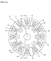
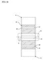
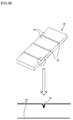
- FIG. 1A and Fig. 1B showing a section taken along the line I-I of Fig. 1A show a permanent magnet embedded type rotating electric machine A to which magnet bodies for field pole 80 formed by magnet pieces which are manufactured by a cutting method and a cutting device according to the present embodiment are applied (hereinafter, simply referred to as the "rotating electric machine A").
- the rotating electric machine A is formed by an annular stator 10 forming a part of a casing, and a columnar rotor 20 arranged coaxially to this stator 10.
- the stator 10 is formed by a stator core 11, and a plurality of coils 12.
- the plurality of coils 12 is housed in slots 13 formed at equal angle intervals on the same circumference around axial center O in the stator core 11.
- the rotor 20 is formed by a rotor core 21, a rotation shaft 23 to be rotated integrally with the rotor core 21, and the plurality of magnet bodies for field pole 80.
- the plurality of magnet bodies for field pole 80 is housed in slots 22 formed at equal angle intervals on the same circumference around the axial center O.
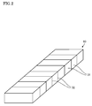
- each of the magnet bodies for field pole 80 housed in the slots 22 of the rotor 20 is formed as a collective body of magnet pieces 31 in which the plurality of magnet pieces 31 is aligned in a line.
- Each of the magnet pieces 31 is divided by cutting a plate shape magnet body 30 whose entire circumferential surface is covered with a coating film having an anti-rust effect, the magnet body having upper and lower surfaces of an oblong shape, along the short direction of the oblong shape.
- the magnet body for field pole 80 is formed by bonding cut surfaces of the plurality of divided magnet pieces 31 to each other with resin 32.
- resin having a performance of resisting heat of about 200°C is used as the resin 32, and electrically insulates the adjacent magnet pieces 31.
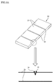
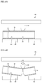
- brittle sections including cutout grooves 33 or the like in parts of the magnet body 30 to be cut (cutting planed lines) as shown in Fig. 3A .
- the cutout grooves 33 provided as the brittle sections the more depth from surfaces are, and the sharper leading ends of the cutout grooves 33 are, the more flatness of the cut surfaces in a case of cutting as the magnet pieces 31 is improved.
- a formation method of the cutout grooves 33 includes a method of providing the cutout grooves in a molding step of the magnet body 30 by protrusions for forming grooves provided in a mold of the magnet body 30, a method by mechanical processing with a dicer, a slicer, or the like, a method by laser beam irradiation, and wire cut electric discharge machining.
- the cutout grooves 33 are formed by the mechanical processing, the laser beam irradiation, and the wire cut electric discharge machining, the coating film 35 on the surface of the magnet body 30 is also cut out at the same time.
- burrs 34 are generated along the cutout grooves 33.
- the burrs 34 are removed in a deburring step as shown in Fig. 3B .
- the magnet body 30 is cut along the cutout grooves 33 into the plurality of magnet pieces 31 as shown in Fig. 3C .
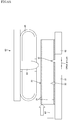
- Figs. 4A and 4B show an outline of a cutting device 40 serving as a comparative example 1 in which the cutting step shown in Fig. 3C is performed.
- the cutting device 40 is a device in which the magnet body 30 is mounted in a state where the magnet body is suspended between a pair of dies 41, 42, a blade 43 is lowered to the suspended part from the upper side, and the magnet body 30 is cut by three-point bending.
- the cutting device 40 includes the pair of dies 41, 42 serving as a lower die on which the magnet body 30 is suspended and mounted, the blade 43 adapted to cut the magnet body 30 by squeezing in the suspended part of the magnet body 30, and a magnet conveyance device (not shown) adapted to feed the magnet body 30 to a part immediately below the blade 43 from one end part ( Fig. 4A ).
- the blade 43 cuts the magnet body 30 by pressing an upper surface of the magnet body 30 suspended over the pair of dies 41, 42 downward.
- the blade 43 is positioned in such a manner that a leading end is placed in the middle between the pair of dies 41, 42, and driven by for example servo press, mechanical press, hydraulic press, or the like.
- the cutting device 40 is formed as described above, and the magnet body 30 including the cutout grooves 33 are provided is suspended and mounted on upper surfaces of the pair of dies 41, 42. It should be noted that the magnet body 30 is mounted on the pair of dies 41, 42 in such a manner that the cutout groove 33 preliminarily provided at a desired cutting position, that is, on the cutting planned line is placed to face the dies 41, 42.
- the blade 43 In a state where the blade is positioned in such a manner that the cutout groove 33 serving as the cutting planned line is placed in the middle between the pair of dies 41, 42 by the magnet conveyance device (not shown), the blade 43 is lowered. When the blade 43 is lowered, the blade 43 presses a back part of the cutout groove 33 downward, and the magnet body 30 is cut along the cutout groove 33 by three-point bending of the blade 43 and adjacent edge sections 41a, 42a of the pair of dies 41, 42 ( Fig. 4B ).
- the coating film 35 covering the surface of the magnet body 30 is cut on the side of a side surface of the magnet body 30 in accordance with progress of the cut surfaces generated by the cutout groove 33 but not cut on the side of the upper surface of the magnet body 30 with which the blade 43 is abutted. That is, the cut magnet piece 31 and the pre-cut magnet body 30 are coupled to each other by the uncut coating film 35 on the side of the upper surface.
- the coating film 35 is made of a ductile material, and because at the time of cutting the magnet body 30, the coating film 35 on the side of the upper surface of the magnet body 30 is abutted with the blade 43 in the part of the cutting planned line, pressed downward, and just bent. Therefore, generation of tensile force to separate the cut coating film 35 on the side of the upper surface of the magnet piece 31 and the uncut coating film 35 remains weak, so that the coating film 35 is not drawn out enough to be cut and hence not cut.
- the cutting device 40 of the comparative example 2 includes the magnet holder 45 to be moved up and down together with the blade 43 in addition to the cutting device 40 of the comparative example 1.
- the blade 43 is lowered. Following lowering of the blade 43, firstly, the magnet holder 45 is brought into contact with the upper surface of the magnet body 30 to suppress movement of the magnet body 30 ( Fig. 5A ). Further, when the blade 43 is lowered, the blade 43 presses the back part of the cutout groove 33 downward, and the magnet body 30 is cut along the cutout groove 33 by three-point bending of the blade 43 and the adjacent edge sections 41a, 42a of the pair of dies 41, 42 ( Fig. 5B ).
- the coating film 35 on the side of the upper surface of the magnet body 30 is abutted with the blade 43 in the part of the cutting planned line, pressed downward, and just bent.
- This bent amount is smaller than the comparative example 1 since the magnet body 30 and the magnet piece 31 are held from the upper side by the magnet holder 45. Therefore, the generation of the tensile force to separate the coating film 35 on the side of the upper surface of the cut magnet piece 31 and the coating film 35 on the side of the upper surface of the pre-cut magnetic body 30 becomes further weaker, so that the coating film 35 is not drawn out enough to be cut and hence not cut.
- the cutting step for cutting the magnet body 30 is performed as follows.
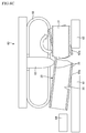
- Figs. 6A to 6D are views showing a cutting step by a cutting device 60 according to the present embodiment.
- the cutting device 60 according to the present embodiment described herein includes a magnet holder 65 adapted to prevent scatter of the magnet piece 31 by stress release at the moment of cutting as well as the comparative example 2. However, as described later, this magnet holder 65 effectively acts on cutting of the coating film 35 but not an essential configuration for the cutting device 60 of the present embodiment.
- a feeding amount of the magnet body 30 is adjusted in such a manner that a position in the feeding direction of the magnet body 30 mounted on a pair of dies 61, 62 serving as a support section becomes a position where the cutout groove 33 is offset to the leading end side in the feeding direction of the magnet body 30 from an abutment part 73 of a blade 63 (to the right side in the figure) ( Fig. 6A ). That is, at the time of cutting the magnet body 30, the cutting groove 33 is arranged not immediately below the abutment part 73 of the blade 63 but displaced in the feeding direction of the magnet body 30 by a predetermined offset amount.
- the magnet body 30 is conveyed by pushing out the magnet body 30 in the conveying direction by a magnet conveyance device 64 serving as a feeding means.
- the magnet conveyance device 64 is formed by for example a LM guide in which an AC servomotor and ball screws are combined or the like, and is capable of feeding the magnet body 30 in the feeding direction by a predetermined amount and stopping the magnet body at an arbitrary position.
- the magnet body 30 is arranged in such a manner that the cutout groove 33 of the magnet body 30 is offset to the right side in the figure from the abutment part 73 of the blade 63.
- An upper limit of the predetermined offset amount is 1 [mm]. By making the upper limit of the offset amount 1 [mm], deterioration of position precision and surface properties of the cut surfaces due to offset of a position of the cutout groove and a blade position can be prevented.
- the predetermined offset amount is specifically for example about 0.6 [mm]. This offset amount is adjusted by being increased or decreased in accordance with the position precision and the surface properties of the cut surfaces formed between the cut magnet piece 31 and the magnet body 30.
- a start position of a crack is the cutout groove 33 serving as the brittle section.
- the blade 63 is lowered. Following lowering of the blade 63, firstly, the magnet holder 65 is brought into contact with the upper surface of the magnet body 30 to suppress the movement of the magnet body 30. Further, when the blade 63 is lowered, as shown in Fig. 6B , the blade 63 presses the back part of the magnet body 30 offset from the cutout groove 33 downward, and the magnet body 30 is cut along the cutout groove 33 by three-point bending of the blade 63 and adjacent edge sections 61a, 62a of the pair of dies 61, 62 ( Fig. 6B ). The blade 63 is stopped at a lowering end. Lowering speed of the blade 63 is for example preferably 30 [mm/sec] or higher.
- the magnet body 30 immediately after cutting is obliquely inclined with a leading end part in the conveying direction being placed on the lower side in a state where the magnet body is in contact with the lowered blade 63, and the magnet piece 31 cut at a leading end of the magnet body 30 is obliquely inclined with a rear end part in the conveying direction being placed on the lower side.
- the leading end part in the conveying direction of the magnet body 30 is placed on the front side in the conveying direction of an abutment position of the blade 63.
- an up-and-down position of a leading end of the magnet body 30 and a rear end of the magnet piece 31 is lower than the comparative examples 1 and 2.
- an oblique inclination angle of the magnet piece 31 in which the rear end part in the conveying direction is placed on the lower side is also increased.
- the coating film 35 of the magnet body 30 and the magnet piece 31 on the leading end side of the magnet body is cut on the side of the side surface of the magnet body 30 and the magnet piece 31 by the cut surfaces generated by the cutout groove 33 but not cut on the side of the upper surface of the magnet body 30.
- the rear end of the magnet piece 31 on the leading end side cut from the magnet body 30 is connected to the magnet body 30 whose front end is pushed down by the blade 63 only by the coating film 35 on the upper surface in the cut surface part.
- the magnet piece is not in contact with the blade 63 and movement thereof is not restricted.
- Moment to rotate and restore the magnet piece 31 in the arrow direction about the edge section 62a of the die 62 from an inclined posture acts on the magnet piece 31 on the leading end side by self-weight of the magnet piece. This rotating and restoring moment restores the inclined posture of the magnet piece 31 along the die 62 ( Fig. 6C ).
- This action of restoring the magnet piece 31 from the inclined posture is made more reliable by displacing the position of the magnet piece forward in the conveying direction before cutting.
- the action of restoring the magnet piece 31 from the inclined posture can be furthermore enhanced.
- an upper surface rear end part of the magnet piece 31 is moved upward away from an upper surface leading end part of the magnet body 30.
- the coating film 35 on the side of the upper surface of the magnet body 30 and the magnet piece 31 is drawn in the separated part, and the coating film 35 on the side of the upper surface coupling the magnet body 30 and the magnet piece 31 is cut and separated in the separated part. Since the up-and-down position of the rear end of the magnet piece 31 is lower than the comparative examples 1 and 2 as described above, an action of drawing the coating film 35 on the side of the upper surface is executed by a large stroke, so that cut and separation of the coating film 35 are reliably executed.
- the magnet body 30 and the magnet piece 31 are completely cut and separated including the coating film 35 ( Fig. 6D ).
- the magnet body 30 is fed in the feeding direction by a volume of one magnet piece 31 by the magnet conveyance device 64, the magnet piece 31 is cut including the coating film 35 by the same procedure, and the above procedure is repeated for the number of times that cutting is required.
- the above rotating and restoring moment generated in the cut magnet piece 31 is increased in proportion to length between the edge section 62a of the die 62 and a front end in the conveying direction of the magnet piece 31. Therefore, in a state where the blade 63 is stopped at the lowering end of the cutting action, the magnet body 30 may be pushed out in the conveying direction by the magnet conveyance device 64 and a position of the magnet piece 31 on the leading end side cut from the magnet body 30 may also be displaced in the conveying direction.
- the length between the edge section 62a of the die 62 and the front end in the conveying direction of the magnet piece 31 can be increased, and the moment to rotate and restore the magnet piece 31 in the arrow direction from the inclined posture to set the magnet piece along the supporting die 62 by the self-weight of the magnet piece can also be increased. Therefore, the action of restoring the magnet piece 31 from the inclined posture can be furthermore enhanced, so that cutting of the coating film 35 can be made furthermore reliable.
Landscapes
- Engineering & Computer Science (AREA)
- Power Engineering (AREA)
- Mechanical Engineering (AREA)
- Manufacturing & Machinery (AREA)
- Physics & Mathematics (AREA)
- Optics & Photonics (AREA)
- Plasma & Fusion (AREA)
- Life Sciences & Earth Sciences (AREA)
- Forests & Forestry (AREA)
- Permanent Field Magnets Of Synchronous Machinery (AREA)
- Manufacture Of Motors, Generators (AREA)
Abstract
Description
- The present invention relates to a cutting method and a cutting device of manufacturing a magnet piece forming a magnet body for field pole to be arranged in a rotating electric machine.
- As a magnet body for field pole to be arranged in a rotating electric machine, a magnet body for field pole formed by cutting a plate shape magnet body (hereinafter, simply referred to as the "magnet body") into a plurality of magnet pieces and bonding the plurality of magnet pieces to each other is conventionally known. Since such a magnet body for field pole is formed by the plurality of magnet pieces, the volume of an individual magnet piece can be reduced, so that an overcurrent generated in the magnet piece by a change in a magnetic field due to rotation of a rotor can be reduced. Thereby, heat generation of the magnet body for field pole following the generation of the overcurrent is suppressed, so that irreversible thermal demagnetization can be prevented.
-
JP2009-142081A - The magnet body is fed in the longitudinal direction on the die, and a leading end part in the feeding direction is successively cut by the blade one by one. The magnet body is cut by squeezing in the blade downward from the upper parts of the cutting planned lines in a state where the magnet body is supported by the die on both sides of the cutting planned lines. That is, the magnet body is cut by three-point bending.
- Since the magnet body is susceptible to rust, a surface of the magnet body is coated with a material having an anti-rust effect. This coating film material is a ductile material. Thus, there is sometimes a case where at the time of cutting the magnet body, the coating film is not drawn out enough to be cut in parts of the cutting planned lines, so that the coating film is not cut. In a case where the coating film is not cut, the cut magnet piece and the pre-cut magnet body are coupled to each other by the coating film. As a result, a disadvantage that at the time of conveying the cut magnet piece to the following step, the pre-cut magnet body is conveyed at the same time is subsequently generated.
- The present invention is achieved in consideration with the above problem, and an object thereof is to provide a cutting method and a cutting device favorable for manufacturing a magnet piece forming a magnet body for field pole to be arranged in a rotating electric machine by cutting a magnet body including a coating film.
- According to one embodiment of this invention, a cutting method of manufacturing a magnet piece forming a magnet body for field pole to be arranged in a rotating electric machine by cutting a permanent magnet body, comprising: forming a brittle section on at least one surface of the permanent magnet body including a deterioration preventive coating film on a surface at a cutting planned position extending in the width direction of the magnet body; in a state where the magnet body having the brittle section being placed on the lower surface side is supported at two support points from the lower side, feeding the magnet body to a position where the brittle section is arranged between both the support points; and cutting the magnet body into a cut magnet body and a magnet piece smaller than the cut magnet body including the coating film by pressing the magnet body from the upper side of a position offset rearward in the feeding direction from the brittle section between both the support points.
-
- [
Fig. 1A] Fig. 1A is a schematic configuration diagram showing a configuration of major parts of a permanent magnet type rotating electric machine in which magnet bodies for field pole formed by magnet pieces which are manufactured by a cutting method and a cutting device according to the present embodiment are applied. - [
Fig. 1B] Fig. 1B is a sectional view showing a section taken along the line I-I of the permanent magnet type rotating electric machine ofFig. 1A . - [
Fig. 2] Fig. 2 is a configuration diagram showing a configuration of the magnet body for field pole. - [
Fig. 3A] Fig. 3A is a view for illustrating a groove making step of the magnet body. - [
Fig. 3B] Fig. 3B is a view for illustrating a deburring step of the magnet body. - [
Fig. 3C] Fig. 3C is a view for illustrating a cutting step of the magnet body. - [
Fig. 4A] Fig. 4A is a view showing a cutting step of the cutting device as a comparative example 1. - [
Fig. 4B] Fig. 4B is a view showing the cutting step of the cutting device as the comparative example 1. - [
Fig. 5A] Fig. 5A is a view showing a cutting step of the cutting device as a comparative example 2. - [
Fig. 5B] Fig. 5B is a view showing the cutting step of the cutting device as the comparative example 2. - [
Fig. 5C] Fig. 5C is a view showing the cutting step of the cutting device as the comparative example 2. - [
Fig. 6A] Fig. 6A is a view showing a cutting step of the cutting device according to a first embodiment. - [
Fig. 6B] Fig. 6B is a view showing the cutting step of the cutting device according to the first embodiment. - [
Fig. 6C] Fig. 6C is a view showing the cutting step of the cutting device according to the first embodiment. - [
Fig. 6D] Fig. 6D is a view showing the cutting step of the cutting device according to the first embodiment. - Hereinafter, an embodiment of the present invention will be described with reference to the attached drawings.
-
Fig. 1A andFig. 1B showing a section taken along the line I-I ofFig. 1A show a permanent magnet embedded type rotating electric machine A to which magnet bodies forfield pole 80 formed by magnet pieces which are manufactured by a cutting method and a cutting device according to the present embodiment are applied (hereinafter, simply referred to as the "rotating electric machine A"). - The rotating electric machine A is formed by an
annular stator 10 forming a part of a casing, and acolumnar rotor 20 arranged coaxially to thisstator 10. - The
stator 10 is formed by astator core 11, and a plurality ofcoils 12. The plurality ofcoils 12 is housed inslots 13 formed at equal angle intervals on the same circumference around axial center O in thestator core 11. - The
rotor 20 is formed by arotor core 21, arotation shaft 23 to be rotated integrally with therotor core 21, and the plurality of magnet bodies forfield pole 80. The plurality of magnet bodies forfield pole 80 is housed inslots 22 formed at equal angle intervals on the same circumference around the axial center O. - As shown in
Fig. 2 , each of the magnet bodies forfield pole 80 housed in theslots 22 of therotor 20 is formed as a collective body ofmagnet pieces 31 in which the plurality ofmagnet pieces 31 is aligned in a line. Each of themagnet pieces 31 is divided by cutting a plateshape magnet body 30 whose entire circumferential surface is covered with a coating film having an anti-rust effect, the magnet body having upper and lower surfaces of an oblong shape, along the short direction of the oblong shape. The magnet body forfield pole 80 is formed by bonding cut surfaces of the plurality of dividedmagnet pieces 31 to each other withresin 32. For example, resin having a performance of resisting heat of about 200°C is used as theresin 32, and electrically insulates theadjacent magnet pieces 31. Thereby, an overcurrent generated in themagnet piece 31 by a change in an acting magnetic field is reduced by keeping the overcurrent in theindividual magnet piece 31, and heat generation of the magnet body forfield pole 80 following the overcurrent is suppressed, so that irreversible thermal demagnetization can be prevented. - Next, with reference to
Figs. 3A to 3C , a process of manufacturing the plurality ofmagnet pieces 31 from the plateshape magnet body 30 whose entire circumferential surface is covered with acoating film 35 having the anti-rust effect will be described. - In order to cut the
magnet body 30 into the plurality ofmagnet pieces 31, it is effective to preliminarily form brittle sections includingcutout grooves 33 or the like in parts of themagnet body 30 to be cut (cutting planed lines) as shown inFig. 3A . Regarding thecutout grooves 33 provided as the brittle sections, the more depth from surfaces are, and the sharper leading ends of thecutout grooves 33 are, the more flatness of the cut surfaces in a case of cutting as themagnet pieces 31 is improved. - A formation method of the
cutout grooves 33 includes a method of providing the cutout grooves in a molding step of themagnet body 30 by protrusions for forming grooves provided in a mold of themagnet body 30, a method by mechanical processing with a dicer, a slicer, or the like, a method by laser beam irradiation, and wire cut electric discharge machining. In a case where thecutout grooves 33 are formed by the mechanical processing, the laser beam irradiation, and the wire cut electric discharge machining, thecoating film 35 on the surface of themagnet body 30 is also cut out at the same time. - In a case where the
cutout grooves 33 are formed by the laser beam irradiation and the wire cut electric discharge machining, burrs 34 are generated along thecutout grooves 33. Thus, theburrs 34 are removed in a deburring step as shown inFig. 3B . - Successively, in a cutting step, by pressing, in a state where the
cutout grooves 33 are placed to face the lower side, positions corresponding to thegrooves 33 from the side where thecutout grooves 33 are not formed by a blade serving as a cutting means to be described later, themagnet body 30 is cut along thecutout grooves 33 into the plurality ofmagnet pieces 31 as shown inFig. 3C . -
Figs. 4A and 4B show an outline of acutting device 40 serving as a comparative example 1 in which the cutting step shown inFig. 3C is performed. - The cutting
device 40 is a device in which themagnet body 30 is mounted in a state where the magnet body is suspended between a pair of dies 41, 42, ablade 43 is lowered to the suspended part from the upper side, and themagnet body 30 is cut by three-point bending. The cuttingdevice 40 includes the pair of dies 41, 42 serving as a lower die on which themagnet body 30 is suspended and mounted, theblade 43 adapted to cut themagnet body 30 by squeezing in the suspended part of themagnet body 30, and a magnet conveyance device (not shown) adapted to feed themagnet body 30 to a part immediately below theblade 43 from one end part (Fig. 4A ). - The
blade 43 cuts themagnet body 30 by pressing an upper surface of themagnet body 30 suspended over the pair of dies 41, 42 downward. Theblade 43 is positioned in such a manner that a leading end is placed in the middle between the pair of dies 41, 42, and driven by for example servo press, mechanical press, hydraulic press, or the like. - The cutting
device 40 is formed as described above, and themagnet body 30 including thecutout grooves 33 are provided is suspended and mounted on upper surfaces of the pair of dies 41, 42. It should be noted that themagnet body 30 is mounted on the pair of dies 41, 42 in such a manner that thecutout groove 33 preliminarily provided at a desired cutting position, that is, on the cutting planned line is placed to face the dies 41, 42. - In a state where the blade is positioned in such a manner that the
cutout groove 33 serving as the cutting planned line is placed in the middle between the pair of dies 41, 42 by the magnet conveyance device (not shown), theblade 43 is lowered. When theblade 43 is lowered, theblade 43 presses a back part of thecutout groove 33 downward, and themagnet body 30 is cut along thecutout groove 33 by three-point bending of theblade 43 and adjacent edge sections 41a, 42a of the pair of dies 41, 42 (Fig. 4B ). - At this time, the
coating film 35 covering the surface of themagnet body 30 is cut on the side of a side surface of themagnet body 30 in accordance with progress of the cut surfaces generated by thecutout groove 33 but not cut on the side of the upper surface of themagnet body 30 with which theblade 43 is abutted. That is, thecut magnet piece 31 and thepre-cut magnet body 30 are coupled to each other by theuncut coating film 35 on the side of the upper surface. - This is thought to be because the
coating film 35 is made of a ductile material, and because at the time of cutting themagnet body 30, thecoating film 35 on the side of the upper surface of themagnet body 30 is abutted with theblade 43 in the part of the cutting planned line, pressed downward, and just bent. Therefore, generation of tensile force to separate thecut coating film 35 on the side of the upper surface of themagnet piece 31 and theuncut coating film 35 remains weak, so that thecoating film 35 is not drawn out enough to be cut and hence not cut. - The above problem becomes more remarkable in a
cutting device 40 of a comparative example 2 in which movement of themagnet piece 31 is suppressed by pressing amagnet holder 45 onto themagnet body 30 and scatter of themagnet piece 31 is prevented by stress release at the moment of cutting as shown inFigs. 5A to 5C . That is, the cuttingdevice 40 of the comparative example 2 includes themagnet holder 45 to be moved up and down together with theblade 43 in addition to thecutting device 40 of the comparative example 1. - In a state where the blade is positioned in such a manner that the
cutout groove 33 serving as the cutting planned line is placed in the middle between the pair of dies 41, 42 by the magnet conveyance device (not shown), theblade 43 is lowered. Following lowering of theblade 43, firstly, themagnet holder 45 is brought into contact with the upper surface of themagnet body 30 to suppress movement of the magnet body 30 (Fig. 5A ). Further, when theblade 43 is lowered, theblade 43 presses the back part of thecutout groove 33 downward, and themagnet body 30 is cut along thecutout groove 33 by three-point bending of theblade 43 and the adjacent edge sections 41a, 42a of the pair of dies 41, 42 (Fig. 5B ). - At this time, the
coating film 35 on the side of the upper surface of themagnet body 30 is abutted with theblade 43 in the part of the cutting planned line, pressed downward, and just bent. This bent amount is smaller than the comparative example 1 since themagnet body 30 and themagnet piece 31 are held from the upper side by themagnet holder 45. Therefore, the generation of the tensile force to separate thecoating film 35 on the side of the upper surface of thecut magnet piece 31 and thecoating film 35 on the side of the upper surface of the pre-cutmagnetic body 30 becomes further weaker, so that thecoating film 35 is not drawn out enough to be cut and hence not cut. - Following lifting of the
blade 43 after that, in a state where themagnet body 30 and themagnet piece 31 are connected by theuncut coating film 35 on the side of the upper surface, the magnet body and the magnet piece are restored from a bent state by the magnet holder 45 (Fig. 5C ). - Thus, in the present embodiment, the cutting step for cutting the
magnet body 30 is performed as follows. -
Figs. 6A to 6D are views showing a cutting step by a cuttingdevice 60 according to the present embodiment. The cuttingdevice 60 according to the present embodiment described herein includes amagnet holder 65 adapted to prevent scatter of themagnet piece 31 by stress release at the moment of cutting as well as the comparative example 2. However, as described later, thismagnet holder 65 effectively acts on cutting of thecoating film 35 but not an essential configuration for thecutting device 60 of the present embodiment. - In the present embodiment, firstly, a feeding amount of the
magnet body 30 is adjusted in such a manner that a position in the feeding direction of themagnet body 30 mounted on a pair of dies 61, 62 serving as a support section becomes a position where thecutout groove 33 is offset to the leading end side in the feeding direction of themagnet body 30 from an abutment part 73 of a blade 63 (to the right side in the figure) (Fig. 6A ). That is, at the time of cutting themagnet body 30, the cuttinggroove 33 is arranged not immediately below the abutment part 73 of theblade 63 but displaced in the feeding direction of themagnet body 30 by a predetermined offset amount. - The
magnet body 30 is conveyed by pushing out themagnet body 30 in the conveying direction by amagnet conveyance device 64 serving as a feeding means. Themagnet conveyance device 64 is formed by for example a LM guide in which an AC servomotor and ball screws are combined or the like, and is capable of feeding themagnet body 30 in the feeding direction by a predetermined amount and stopping the magnet body at an arbitrary position. - In the present embodiment, the
magnet body 30 is arranged in such a manner that thecutout groove 33 of themagnet body 30 is offset to the right side in the figure from the abutment part 73 of theblade 63. An upper limit of the predetermined offset amount is 1 [mm]. By making the upper limit of the offset amount 1 [mm], deterioration of position precision and surface properties of the cut surfaces due to offset of a position of the cutout groove and a blade position can be prevented. The predetermined offset amount is specifically for example about 0.6 [mm]. This offset amount is adjusted by being increased or decreased in accordance with the position precision and the surface properties of the cut surfaces formed between thecut magnet piece 31 and themagnet body 30. A start position of a crack is thecutout groove 33 serving as the brittle section. - In a state where the
magnet body 30 is positioned as described above, theblade 63 is lowered. Following lowering of theblade 63, firstly, themagnet holder 65 is brought into contact with the upper surface of themagnet body 30 to suppress the movement of themagnet body 30. Further, when theblade 63 is lowered, as shown inFig. 6B , theblade 63 presses the back part of themagnet body 30 offset from thecutout groove 33 downward, and themagnet body 30 is cut along thecutout groove 33 by three-point bending of theblade 63 andadjacent edge sections Fig. 6B ). Theblade 63 is stopped at a lowering end. Lowering speed of theblade 63 is for example preferably 30 [mm/sec] or higher. - The
magnet body 30 immediately after cutting is obliquely inclined with a leading end part in the conveying direction being placed on the lower side in a state where the magnet body is in contact with the loweredblade 63, and themagnet piece 31 cut at a leading end of themagnet body 30 is obliquely inclined with a rear end part in the conveying direction being placed on the lower side. The leading end part in the conveying direction of themagnet body 30 is placed on the front side in the conveying direction of an abutment position of theblade 63. Thus, an up-and-down position of a leading end of themagnet body 30 and a rear end of themagnet piece 31 is lower than the comparative examples 1 and 2. Therefore, an oblique inclination angle of themagnet piece 31 in which the rear end part in the conveying direction is placed on the lower side is also increased. In this state, thecoating film 35 of themagnet body 30 and themagnet piece 31 on the leading end side of the magnet body is cut on the side of the side surface of themagnet body 30 and themagnet piece 31 by the cut surfaces generated by thecutout groove 33 but not cut on the side of the upper surface of themagnet body 30. - At this time, the rear end of the
magnet piece 31 on the leading end side cut from themagnet body 30 is connected to themagnet body 30 whose front end is pushed down by theblade 63 only by thecoating film 35 on the upper surface in the cut surface part. The magnet piece is not in contact with theblade 63 and movement thereof is not restricted. Moment to rotate and restore themagnet piece 31 in the arrow direction about theedge section 62a of the die 62 from an inclined posture acts on themagnet piece 31 on the leading end side by self-weight of the magnet piece. This rotating and restoring moment restores the inclined posture of themagnet piece 31 along the die 62 (Fig. 6C ). This action of restoring themagnet piece 31 from the inclined posture is made more reliable by displacing the position of the magnet piece forward in the conveying direction before cutting. By holding force by themagnet holder 65, the action of restoring themagnet piece 31 from the inclined posture can be furthermore enhanced. - Thereby, an upper surface rear end part of the
magnet piece 31 is moved upward away from an upper surface leading end part of themagnet body 30. By this separation movement, thecoating film 35 on the side of the upper surface of themagnet body 30 and themagnet piece 31 is drawn in the separated part, and thecoating film 35 on the side of the upper surface coupling themagnet body 30 and themagnet piece 31 is cut and separated in the separated part. Since the up-and-down position of the rear end of themagnet piece 31 is lower than the comparative examples 1 and 2 as described above, an action of drawing thecoating film 35 on the side of the upper surface is executed by a large stroke, so that cut and separation of thecoating film 35 are reliably executed. - When the
blade 63 is lifted up, themagnet body 30 and themagnet piece 31 are completely cut and separated including the coating film 35 (Fig. 6D ). For cutting thenext magnet piece 31, themagnet body 30 is fed in the feeding direction by a volume of onemagnet piece 31 by themagnet conveyance device 64, themagnet piece 31 is cut including thecoating film 35 by the same procedure, and the above procedure is repeated for the number of times that cutting is required. - The above rotating and restoring moment generated in the
cut magnet piece 31 is increased in proportion to length between theedge section 62a of thedie 62 and a front end in the conveying direction of themagnet piece 31. Therefore, in a state where theblade 63 is stopped at the lowering end of the cutting action, themagnet body 30 may be pushed out in the conveying direction by themagnet conveyance device 64 and a position of themagnet piece 31 on the leading end side cut from themagnet body 30 may also be displaced in the conveying direction. In such a way, by displacing the position of themagnet piece 31 on the leading end side in the conveying direction, the length between theedge section 62a of thedie 62 and the front end in the conveying direction of themagnet piece 31 can be increased, and the moment to rotate and restore themagnet piece 31 in the arrow direction from the inclined posture to set the magnet piece along the supportingdie 62 by the self-weight of the magnet piece can also be increased. Therefore, the action of restoring themagnet piece 31 from the inclined posture can be furthermore enhanced, so that cutting of thecoating film 35 can be made furthermore reliable. - In the present embodiment, the following effects are exerted.
- (A) By feeding, in a state where the
magnet body 30 including thecutout grooves 33 serving as the brittle sections on the lower surface along cutting planned positions is supported by the dies 61, 62 serving as two support points from the lower side, themagnet body 30 to the position where the brittle section is arranged between both the support points, and pressing themagnet body 30 from the upper side of the position offset rearward in the feeding direction from the brittle section between both the support points, themagnet body 30 is cut into thecut magnet body 30 and themagnet piece 31 smaller than thecut magnet body 30 while cutting thecoating film 35. That is, by the self-weight of themagnet piece 31, the moment to rotate, restore, and set the magnet piece along the die 62 serving as the support point supporting themagnet piece 31 is generated. Thus, thecoating film 35 continuing to thecut magnet body 30 can be cut. There is no need for an additional means adapted to cut thecoating film 35. Thus, the cuttingdevice 60 can have a simple configuration. - (B) The cutting step is performed while holding at least the
magnet piece 31 among themagnet body 30 and themagnet piece 31 by themagnet holder 65 from the upper side. Thus, the moment to rotate, restore, and set the magnet piece along the die 62 serving as the support point supporting thecut magnet piece 31 can be increased, so that the cutting of thecoating film 35 can be made furthermore reliable. - (C) By adding an action of displacing the
cut magnet piece 31 in the feeding direction by themagnet conveyance device 64, by the self-weight of the magnet piece, the moment to rotate, restore, and set the magnet piece along the die 62 serving as the support point supporting themagnet piece 31 can be increased, so that the cutting of thecoating film 35 can be made furthermore reliable. - (D) The
cutout grooves 33 serving as the brittle sections are provided at equal intervals in the feeding direction on at least one surface of themagnet body 30, and the offset amount is the same in the cutting step of all the brittle sections. Therefore, at the time of first cutting, when a positional relationship between the brittle section and theblade 63 is set to obtain optimal position precision and surface properties of the cut surfaces, themagnet body 30 is always constantly conveyed for each cutting action. Thus, a conveying action can be made simple. - (E) The
cutout grooves 33 serving as the brittle sections are made by laser beam irradiation. Thus, the position precision of the obtained brittle sections is improved. - The embodiment of the present invention is described above. The above embodiment only shows part of application examples of the present invention but does not intend to limit the technical scope of the present invention to specific configurations of the above embodiment.
- This application claims priority from
Japanese Patent Application No. 2013-177831
Claims (10)
- A cutting method of manufacturing a magnet piece forming a magnet body for field pole to be arranged in a rotating electric machine by cutting a permanent magnet body, comprising:forming a brittle section on at least one surface of the permanent magnet body including a deterioration preventive coating film on a surface at a cutting planned position extending in the width direction of the magnet body;in a state where the magnet body having the brittle section being placed on the lower surface side is supported at two support points from the lower side, feeding the magnet body to a position where the brittle section is arranged between both the support points; andcutting the magnet body into a cut magnet body and a magnet piece smaller than the cut magnet body including the coating film by pressing the magnet body from the upper side of a position offset rearward in the feeding direction from the brittle section between both the support points.
- The cutting method according to claim 1, wherein
the cutting is performed while at least the magnet piece among the magnet body and the magnet piece is held from the upper side. - The cutting method according to claim 1 or 2, wherein
the cutting includes an action of displacing a position of the magnet body in the feeding direction in a state where the magnet body is pressed. - The cutting method according to any of claims 1 to 3, wherein
the brittle sections are provided at equal intervals in the feeding direction on at least one surface of the magnet body, and
the offset amount is the same in the cutting of all the brittle sections. - The cutting method according to any of claims 1 to 4, wherein
the forming the brittle section is to make the brittle section by laser beam irradiation. - A cutting device of manufacturing a magnet piece forming a magnet body for field pole to be arranged in a rotating electric machine by cutting a permanent magnet body, comprising:a support section adapted to support the magnet body in which a brittle section is formed on a lower surface along a cutting planned position at two support points from the lower side;a feeding means adapted to feed the magnet body to a position where the brittle section is arranged between both the support points; anda cutting means adapted to cut the magnet body into a cut magnet body and a magnet piece smaller than the cut magnet body including a coating film of the magnet body by press the magnet body from the upper side of a position offset rearward in the feeding direction from the brittle section between both the support points,.
- The cutting device according to claim 6, wherein
the cutting means includes a magnet holder adapted to hold at least the magnet piece among the magnet body and the magnet piece from the upper side. - The cutting device according to claim 6 or 7, wherein
the feeding means performs an action of displacing a position of the magnet body in the feeding direction in a state where the magnet body is pressed by the cutting means. - The cutting device according to any of claims 6 to 8, wherein the brittle sections are provided at equal intervals in the feeding direction on at least one surface of the magnet body, and
the offset amount is the same in cutting of all the brittle sections. - The cutting device according to any of claims 6 to 9, wherein the brittle section is processed by laser beam irradiation.
Applications Claiming Priority (2)
| Application Number | Priority Date | Filing Date | Title |
|---|---|---|---|
| JP2013177831 | 2013-08-29 | ||
| PCT/JP2014/071932 WO2015029882A1 (en) | 2013-08-29 | 2014-08-21 | Cutting method and cutting device for manufacturing magnet piece constituting magnet body for field pole to be arranged in rotary electric machine |
Publications (3)
| Publication Number | Publication Date |
|---|---|
| EP3041114A1 true EP3041114A1 (en) | 2016-07-06 |
| EP3041114A4 EP3041114A4 (en) | 2016-08-31 |
| EP3041114B1 EP3041114B1 (en) | 2019-07-24 |
Family
ID=52586442
Family Applications (1)
| Application Number | Title | Priority Date | Filing Date |
|---|---|---|---|
| EP14838975.2A Active EP3041114B1 (en) | 2013-08-29 | 2014-08-21 | Cutting method and cutting device for manufacturing magnet piece constituting magnet body for field pole to be arranged in rotary electric machine |
Country Status (5)
| Country | Link |
|---|---|
| US (1) | US9754719B2 (en) |
| EP (1) | EP3041114B1 (en) |
| JP (1) | JP6079887B2 (en) |
| CN (1) | CN105580245B (en) |
| WO (1) | WO2015029882A1 (en) |
Families Citing this family (4)
| Publication number | Priority date | Publication date | Assignee | Title |
|---|---|---|---|---|
| US10279504B2 (en) | 2013-10-09 | 2019-05-07 | Nissan Motor Co., Ltd. | Manufacture method and manufacturing device for manufacturing magnet piece constituting magnet body for field pole disposed on rotating electric machine |
| CN106710786B (en) * | 2015-07-29 | 2019-09-10 | 胜美达集团株式会社 | The manufacturing method of miniaturized electronic devices, electronic circuit board and miniaturized electronic devices |
| FR3064423B1 (en) * | 2017-03-22 | 2019-11-15 | Whylot Sas | ROTOR FOR MOTOR OR ELECTROMAGNETIC GENERATOR WITH ALVEOLAR STRUCTURE COMPRISING ALVEOLES FOR THE HOUSING OF RESPECTIVE MAGNETS |
| CN113228207B (en) | 2018-12-25 | 2023-08-01 | 大赛璐美华株式会社 | Rare earth magnet precursor or rare earth magnet molded body having roughened structure on surface, and method for producing same |
Family Cites Families (14)
| Publication number | Priority date | Publication date | Assignee | Title |
|---|---|---|---|---|
| JPH0919918A (en) * | 1995-07-07 | 1997-01-21 | Sony Corp | Dividing device |
| JPH10170880A (en) * | 1996-12-12 | 1998-06-26 | Sony Corp | Panel parting method |
| JP2000324736A (en) * | 1999-05-12 | 2000-11-24 | Mitsubishi Electric Corp | Permanent magnet mounted motor |
| EP1889696B1 (en) * | 2006-08-14 | 2012-07-25 | Blumer Maschinenbau Ag | Punching apparatus and method for using it |
| JP4497198B2 (en) | 2007-12-06 | 2010-07-07 | トヨタ自動車株式会社 | Permanent magnet and method for manufacturing the same, and rotor and IPM motor |
| JP5777849B2 (en) * | 2009-05-29 | 2015-09-09 | 三星ダイヤモンド工業株式会社 | Break device and break method |
| WO2011004490A1 (en) * | 2009-07-10 | 2011-01-13 | トヨタ自動車株式会社 | Device for cleaving magnet and method for cleaving magnet |
| JP2011125105A (en) * | 2009-12-09 | 2011-06-23 | Toyota Motor Corp | Motor with cleft magnet and method of manufacturing the same |
| JP5614096B2 (en) * | 2010-05-19 | 2014-10-29 | 日産自動車株式会社 | Permanent magnet embedded in rotor core of rotating electrical machine and method for manufacturing the same |
| EP2584681B1 (en) * | 2010-06-17 | 2019-06-05 | Nissan Motor Co., Ltd | Method for manufacturing permanent magnets for a dynamo-electric machine |
| JP5494791B2 (en) * | 2011-03-31 | 2014-05-21 | トヨタ自動車株式会社 | Cleaving method, rotor manufacturing method, and cleaving apparatus |
| JP5862156B2 (en) * | 2011-09-26 | 2016-02-16 | 日産自動車株式会社 | Field pole magnet body manufacturing apparatus and method |
| JP6393019B2 (en) | 2011-09-26 | 2018-09-19 | 日産自動車株式会社 | Field pole magnet body manufacturing apparatus and method |
| JP5066292B1 (en) | 2012-02-28 | 2012-11-07 | 敏彦 辻 | 2-stroke internal combustion engine |
-
2014
- 2014-08-21 JP JP2015534173A patent/JP6079887B2/en active Active
- 2014-08-21 WO PCT/JP2014/071932 patent/WO2015029882A1/en active Application Filing
- 2014-08-21 EP EP14838975.2A patent/EP3041114B1/en active Active
- 2014-08-21 CN CN201480053060.8A patent/CN105580245B/en active Active
- 2014-08-21 US US14/911,682 patent/US9754719B2/en active Active
Also Published As
| Publication number | Publication date |
|---|---|
| EP3041114B1 (en) | 2019-07-24 |
| US20160211073A1 (en) | 2016-07-21 |
| US9754719B2 (en) | 2017-09-05 |
| EP3041114A4 (en) | 2016-08-31 |
| WO2015029882A1 (en) | 2015-03-05 |
| CN105580245A (en) | 2016-05-11 |
| CN105580245B (en) | 2017-10-17 |
| JPWO2015029882A1 (en) | 2017-03-02 |
| JP6079887B2 (en) | 2017-02-15 |
Similar Documents
| Publication | Publication Date | Title |
|---|---|---|
| US9754719B2 (en) | Cutting method and cutting device of manufacturing magnet piece forming magnet body for field pole to be arranged in rotating electric machine | |
| KR101332513B1 (en) | Permanent magnet provided to dynamo-electric machine, and method for manufacturing same | |
| US11349378B2 (en) | Coil segment cutting method and coil segment cutting apparatus | |
| JP2016030284A (en) | Cutting method for flat wire and cutting blade tool | |
| EP3765217B1 (en) | Laser assisted machining of electric motor cores | |
| EP3057207B1 (en) | Method and device for manufacturing magnet pieces configuring a field pole magnet to be arranged in a rotary machine | |
| JP7008556B2 (en) | Cutting tool for cutting | |
| CN114945435A (en) | Method for producing a profiled shaped part and wire processing machine | |
| JP5010174B2 (en) | Manufacturing equipment for iron core pieces for rotating electrical machines | |
| JP5849774B2 (en) | A cleaving method and a cleaving apparatus for cleaving a permanent magnet body into a magnet piece constituting a field pole magnet body disposed in a rotating electrical machine | |
| WO2013125513A1 (en) | Method and device for manufacturing magnet pieces for field-pole magnet | |
| JP5919888B2 (en) | A cleaving method and a cleaving apparatus for cleaving a permanent magnet body into a magnet piece constituting a field pole magnet body disposed in a rotating electrical machine | |
| JP4592720B2 (en) | Sheet material punching method | |
| JP2021521013A (en) | Laser-assisted machining of sheet materials | |
| JP3285026B2 (en) | Stripping method of coated conductor wire | |
| CN218938585U (en) | Forming equipment for prefabricated optical cable | |
| JP5935257B2 (en) | Field pole magnet body manufacturing apparatus and method | |
| JP2008245468A (en) | Method of manufacturing part for stator | |
| JP2013141671A (en) | Thomson blade machining method |
Legal Events
| Date | Code | Title | Description |
|---|---|---|---|
| PUAI | Public reference made under article 153(3) epc to a published international application that has entered the european phase |
Free format text: ORIGINAL CODE: 0009012 |
|
| 17P | Request for examination filed |
Effective date: 20160321 |
|
| AK | Designated contracting states |
Kind code of ref document: A1 Designated state(s): AL AT BE BG CH CY CZ DE DK EE ES FI FR GB GR HR HU IE IS IT LI LT LU LV MC MK MT NL NO PL PT RO RS SE SI SK SM TR |
|
| AX | Request for extension of the european patent |
Extension state: BA ME |
|
| A4 | Supplementary search report drawn up and despatched |
Effective date: 20160728 |
|
| RIC1 | Information provided on ipc code assigned before grant |
Ipc: H02K 15/03 20060101AFI20160722BHEP Ipc: B26F 3/00 20060101ALI20160722BHEP Ipc: H02K 1/27 20060101ALN20160722BHEP Ipc: H01F 41/02 20060101ALI20160722BHEP |
|
| DAX | Request for extension of the european patent (deleted) | ||
| STAA | Information on the status of an ep patent application or granted ep patent |
Free format text: STATUS: EXAMINATION IS IN PROGRESS |
|
| 17Q | First examination report despatched |
Effective date: 20170508 |
|
| REG | Reference to a national code |
Ref country code: DE Ref legal event code: R079 Ref document number: 602014050598 Country of ref document: DE Free format text: PREVIOUS MAIN CLASS: H02K0001270000 Ipc: H02K0015030000 |
|
| GRAP | Despatch of communication of intention to grant a patent |
Free format text: ORIGINAL CODE: EPIDOSNIGR1 |
|
| STAA | Information on the status of an ep patent application or granted ep patent |
Free format text: STATUS: GRANT OF PATENT IS INTENDED |
|
| RIC1 | Information provided on ipc code assigned before grant |
Ipc: B23K 103/00 20060101ALN20190326BHEP Ipc: B23K 26/00 20140101ALN20190326BHEP Ipc: H02K 15/03 20060101AFI20190326BHEP Ipc: B26F 3/00 20060101ALI20190326BHEP Ipc: H01F 41/02 20060101ALI20190326BHEP Ipc: B23K 26/359 20140101ALN20190326BHEP Ipc: H02K 1/27 20060101ALN20190326BHEP |
|
| INTG | Intention to grant announced |
Effective date: 20190417 |
|
| GRAS | Grant fee paid |
Free format text: ORIGINAL CODE: EPIDOSNIGR3 |
|
| GRAA | (expected) grant |
Free format text: ORIGINAL CODE: 0009210 |
|
| STAA | Information on the status of an ep patent application or granted ep patent |
Free format text: STATUS: THE PATENT HAS BEEN GRANTED |
|
| RIN1 | Information on inventor provided before grant (corrected) |
Inventor name: MATSUSHITA, YASUSHI Inventor name: HORI, AKIHISA Inventor name: OHSHIMA, TAKUMI Inventor name: KISHI, MICHITO Inventor name: HASEGAWA, KIYOSHI Inventor name: NISHIMURA, KIMIO Inventor name: SEKIKAWA, TAKASHI |
|
| AK | Designated contracting states |
Kind code of ref document: B1 Designated state(s): AL AT BE BG CH CY CZ DE DK EE ES FI FR GB GR HR HU IE IS IT LI LT LU LV MC MK MT NL NO PL PT RO RS SE SI SK SM TR |
|
| REG | Reference to a national code |
Ref country code: GB Ref legal event code: FG4D |
|
| REG | Reference to a national code |
Ref country code: CH Ref legal event code: EP |
|
| REG | Reference to a national code |
Ref country code: DE Ref legal event code: R096 Ref document number: 602014050598 Country of ref document: DE |
|
| REG | Reference to a national code |
Ref country code: AT Ref legal event code: REF Ref document number: 1159389 Country of ref document: AT Kind code of ref document: T Effective date: 20190815 |
|
| REG | Reference to a national code |
Ref country code: IE Ref legal event code: FG4D |
|
| REG | Reference to a national code |
Ref country code: NL Ref legal event code: MP Effective date: 20190724 |
|
| REG | Reference to a national code |
Ref country code: LT Ref legal event code: MG4D |
|
| REG | Reference to a national code |
Ref country code: AT Ref legal event code: MK05 Ref document number: 1159389 Country of ref document: AT Kind code of ref document: T Effective date: 20190724 |
|
| PG25 | Lapsed in a contracting state [announced via postgrant information from national office to epo] |
Ref country code: FI Free format text: LAPSE BECAUSE OF FAILURE TO SUBMIT A TRANSLATION OF THE DESCRIPTION OR TO PAY THE FEE WITHIN THE PRESCRIBED TIME-LIMIT Effective date: 20190724 Ref country code: PT Free format text: LAPSE BECAUSE OF FAILURE TO SUBMIT A TRANSLATION OF THE DESCRIPTION OR TO PAY THE FEE WITHIN THE PRESCRIBED TIME-LIMIT Effective date: 20191125 Ref country code: LT Free format text: LAPSE BECAUSE OF FAILURE TO SUBMIT A TRANSLATION OF THE DESCRIPTION OR TO PAY THE FEE WITHIN THE PRESCRIBED TIME-LIMIT Effective date: 20190724 Ref country code: AT Free format text: LAPSE BECAUSE OF FAILURE TO SUBMIT A TRANSLATION OF THE DESCRIPTION OR TO PAY THE FEE WITHIN THE PRESCRIBED TIME-LIMIT Effective date: 20190724 Ref country code: BG Free format text: LAPSE BECAUSE OF FAILURE TO SUBMIT A TRANSLATION OF THE DESCRIPTION OR TO PAY THE FEE WITHIN THE PRESCRIBED TIME-LIMIT Effective date: 20191024 Ref country code: NL Free format text: LAPSE BECAUSE OF FAILURE TO SUBMIT A TRANSLATION OF THE DESCRIPTION OR TO PAY THE FEE WITHIN THE PRESCRIBED TIME-LIMIT Effective date: 20190724 Ref country code: NO Free format text: LAPSE BECAUSE OF FAILURE TO SUBMIT A TRANSLATION OF THE DESCRIPTION OR TO PAY THE FEE WITHIN THE PRESCRIBED TIME-LIMIT Effective date: 20191024 Ref country code: HR Free format text: LAPSE BECAUSE OF FAILURE TO SUBMIT A TRANSLATION OF THE DESCRIPTION OR TO PAY THE FEE WITHIN THE PRESCRIBED TIME-LIMIT Effective date: 20190724 Ref country code: SE Free format text: LAPSE BECAUSE OF FAILURE TO SUBMIT A TRANSLATION OF THE DESCRIPTION OR TO PAY THE FEE WITHIN THE PRESCRIBED TIME-LIMIT Effective date: 20190724 |
|
| PG25 | Lapsed in a contracting state [announced via postgrant information from national office to epo] |
Ref country code: RS Free format text: LAPSE BECAUSE OF FAILURE TO SUBMIT A TRANSLATION OF THE DESCRIPTION OR TO PAY THE FEE WITHIN THE PRESCRIBED TIME-LIMIT Effective date: 20190724 Ref country code: IS Free format text: LAPSE BECAUSE OF FAILURE TO SUBMIT A TRANSLATION OF THE DESCRIPTION OR TO PAY THE FEE WITHIN THE PRESCRIBED TIME-LIMIT Effective date: 20191124 Ref country code: ES Free format text: LAPSE BECAUSE OF FAILURE TO SUBMIT A TRANSLATION OF THE DESCRIPTION OR TO PAY THE FEE WITHIN THE PRESCRIBED TIME-LIMIT Effective date: 20190724 Ref country code: GR Free format text: LAPSE BECAUSE OF FAILURE TO SUBMIT A TRANSLATION OF THE DESCRIPTION OR TO PAY THE FEE WITHIN THE PRESCRIBED TIME-LIMIT Effective date: 20191025 Ref country code: LV Free format text: LAPSE BECAUSE OF FAILURE TO SUBMIT A TRANSLATION OF THE DESCRIPTION OR TO PAY THE FEE WITHIN THE PRESCRIBED TIME-LIMIT Effective date: 20190724 Ref country code: AL Free format text: LAPSE BECAUSE OF FAILURE TO SUBMIT A TRANSLATION OF THE DESCRIPTION OR TO PAY THE FEE WITHIN THE PRESCRIBED TIME-LIMIT Effective date: 20190724 |
|
| PG25 | Lapsed in a contracting state [announced via postgrant information from national office to epo] |
Ref country code: TR Free format text: LAPSE BECAUSE OF FAILURE TO SUBMIT A TRANSLATION OF THE DESCRIPTION OR TO PAY THE FEE WITHIN THE PRESCRIBED TIME-LIMIT Effective date: 20190724 |
|
| PG25 | Lapsed in a contracting state [announced via postgrant information from national office to epo] |
Ref country code: EE Free format text: LAPSE BECAUSE OF FAILURE TO SUBMIT A TRANSLATION OF THE DESCRIPTION OR TO PAY THE FEE WITHIN THE PRESCRIBED TIME-LIMIT Effective date: 20190724 Ref country code: PL Free format text: LAPSE BECAUSE OF FAILURE TO SUBMIT A TRANSLATION OF THE DESCRIPTION OR TO PAY THE FEE WITHIN THE PRESCRIBED TIME-LIMIT Effective date: 20190724 Ref country code: IT Free format text: LAPSE BECAUSE OF FAILURE TO SUBMIT A TRANSLATION OF THE DESCRIPTION OR TO PAY THE FEE WITHIN THE PRESCRIBED TIME-LIMIT Effective date: 20190724 Ref country code: DK Free format text: LAPSE BECAUSE OF FAILURE TO SUBMIT A TRANSLATION OF THE DESCRIPTION OR TO PAY THE FEE WITHIN THE PRESCRIBED TIME-LIMIT Effective date: 20190724 Ref country code: RO Free format text: LAPSE BECAUSE OF FAILURE TO SUBMIT A TRANSLATION OF THE DESCRIPTION OR TO PAY THE FEE WITHIN THE PRESCRIBED TIME-LIMIT Effective date: 20190724 |
|
| PG25 | Lapsed in a contracting state [announced via postgrant information from national office to epo] |
Ref country code: SK Free format text: LAPSE BECAUSE OF FAILURE TO SUBMIT A TRANSLATION OF THE DESCRIPTION OR TO PAY THE FEE WITHIN THE PRESCRIBED TIME-LIMIT Effective date: 20190724 Ref country code: CZ Free format text: LAPSE BECAUSE OF FAILURE TO SUBMIT A TRANSLATION OF THE DESCRIPTION OR TO PAY THE FEE WITHIN THE PRESCRIBED TIME-LIMIT Effective date: 20190724 Ref country code: LU Free format text: LAPSE BECAUSE OF NON-PAYMENT OF DUE FEES Effective date: 20190821 Ref country code: CH Free format text: LAPSE BECAUSE OF NON-PAYMENT OF DUE FEES Effective date: 20190831 Ref country code: LI Free format text: LAPSE BECAUSE OF NON-PAYMENT OF DUE FEES Effective date: 20190831 Ref country code: MC Free format text: LAPSE BECAUSE OF FAILURE TO SUBMIT A TRANSLATION OF THE DESCRIPTION OR TO PAY THE FEE WITHIN THE PRESCRIBED TIME-LIMIT Effective date: 20190724 Ref country code: IS Free format text: LAPSE BECAUSE OF FAILURE TO SUBMIT A TRANSLATION OF THE DESCRIPTION OR TO PAY THE FEE WITHIN THE PRESCRIBED TIME-LIMIT Effective date: 20200224 Ref country code: SM Free format text: LAPSE BECAUSE OF FAILURE TO SUBMIT A TRANSLATION OF THE DESCRIPTION OR TO PAY THE FEE WITHIN THE PRESCRIBED TIME-LIMIT Effective date: 20190724 |
|
| REG | Reference to a national code |
Ref country code: BE Ref legal event code: MM Effective date: 20190831 |
|
| REG | Reference to a national code |
Ref country code: DE Ref legal event code: R097 Ref document number: 602014050598 Country of ref document: DE |
|
| PLBE | No opposition filed within time limit |
Free format text: ORIGINAL CODE: 0009261 |
|
| STAA | Information on the status of an ep patent application or granted ep patent |
Free format text: STATUS: NO OPPOSITION FILED WITHIN TIME LIMIT |
|
| PG2D | Information on lapse in contracting state deleted |
Ref country code: IS |
|
| PG25 | Lapsed in a contracting state [announced via postgrant information from national office to epo] |
Ref country code: IE Free format text: LAPSE BECAUSE OF NON-PAYMENT OF DUE FEES Effective date: 20190821 |
|
| 26N | No opposition filed |
Effective date: 20200603 |
|
| PG25 | Lapsed in a contracting state [announced via postgrant information from national office to epo] |
Ref country code: SI Free format text: LAPSE BECAUSE OF FAILURE TO SUBMIT A TRANSLATION OF THE DESCRIPTION OR TO PAY THE FEE WITHIN THE PRESCRIBED TIME-LIMIT Effective date: 20190724 Ref country code: BE Free format text: LAPSE BECAUSE OF NON-PAYMENT OF DUE FEES Effective date: 20190831 |
|
| PG25 | Lapsed in a contracting state [announced via postgrant information from national office to epo] |
Ref country code: CY Free format text: LAPSE BECAUSE OF FAILURE TO SUBMIT A TRANSLATION OF THE DESCRIPTION OR TO PAY THE FEE WITHIN THE PRESCRIBED TIME-LIMIT Effective date: 20190724 |
|
| PG25 | Lapsed in a contracting state [announced via postgrant information from national office to epo] |
Ref country code: MT Free format text: LAPSE BECAUSE OF FAILURE TO SUBMIT A TRANSLATION OF THE DESCRIPTION OR TO PAY THE FEE WITHIN THE PRESCRIBED TIME-LIMIT Effective date: 20190724 Ref country code: HU Free format text: LAPSE BECAUSE OF FAILURE TO SUBMIT A TRANSLATION OF THE DESCRIPTION OR TO PAY THE FEE WITHIN THE PRESCRIBED TIME-LIMIT; INVALID AB INITIO Effective date: 20140821 |
|
| PG25 | Lapsed in a contracting state [announced via postgrant information from national office to epo] |
Ref country code: MK Free format text: LAPSE BECAUSE OF FAILURE TO SUBMIT A TRANSLATION OF THE DESCRIPTION OR TO PAY THE FEE WITHIN THE PRESCRIBED TIME-LIMIT Effective date: 20190724 |
|
| PGFP | Annual fee paid to national office [announced via postgrant information from national office to epo] |
Ref country code: GB Payment date: 20230720 Year of fee payment: 10 |
|
| PGFP | Annual fee paid to national office [announced via postgrant information from national office to epo] |
Ref country code: FR Payment date: 20230720 Year of fee payment: 10 Ref country code: DE Payment date: 20230720 Year of fee payment: 10 |