EP3041109A1 - Distributed power supply system and power conditioner - Google Patents
Distributed power supply system and power conditioner Download PDFInfo
- Publication number
- EP3041109A1 EP3041109A1 EP14839163.4A EP14839163A EP3041109A1 EP 3041109 A1 EP3041109 A1 EP 3041109A1 EP 14839163 A EP14839163 A EP 14839163A EP 3041109 A1 EP3041109 A1 EP 3041109A1
- Authority
- EP
- European Patent Office
- Prior art keywords
- power flow
- power
- forward power
- conditioner
- flow threshold
- Prior art date
- Legal status (The legal status is an assumption and is not a legal conclusion. Google has not performed a legal analysis and makes no representation as to the accuracy of the status listed.)
- Granted
Links
Images


Classifications
-
- H—ELECTRICITY
- H02—GENERATION; CONVERSION OR DISTRIBUTION OF ELECTRIC POWER
- H02J—ELECTRIC POWER NETWORKS; CIRCUIT ARRANGEMENTS OR SYSTEMS FOR SUPPLYING OR DISTRIBUTING ELECTRIC POWER; SYSTEMS FOR STORING ELECTRIC ENERGY
- H02J3/00—Circuit arrangements for AC mains or AC distribution networks
- H02J3/38—Arrangements for feeding a single network from two or more generators or sources in parallel; Arrangements for feeding already energised networks from additional generators or sources in parallel
- H02J3/381—Dispersed generators
-
- H—ELECTRICITY
- H02—GENERATION; CONVERSION OR DISTRIBUTION OF ELECTRIC POWER
- H02M—APPARATUS FOR CONVERSION BETWEEN AC AND AC, BETWEEN AC AND DC, OR BETWEEN DC AND DC, AND FOR USE WITH MAINS OR SIMILAR POWER SUPPLY SYSTEMS; CONVERSION OF DC OR AC INPUT POWER INTO SURGE OUTPUT POWER; CONTROL OR REGULATION THEREOF
- H02M1/00—Details of apparatus for conversion
- H02M1/08—Circuits specially adapted for the generation of control voltages for semiconductor devices incorporated in static converters
-
- H—ELECTRICITY
- H02—GENERATION; CONVERSION OR DISTRIBUTION OF ELECTRIC POWER
- H02J—ELECTRIC POWER NETWORKS; CIRCUIT ARRANGEMENTS OR SYSTEMS FOR SUPPLYING OR DISTRIBUTING ELECTRIC POWER; SYSTEMS FOR STORING ELECTRIC ENERGY
- H02J2101/00—Supply or distribution of decentralised, dispersed or local electric power generation
- H02J2101/20—Dispersed power generation using renewable energy sources
-
- H—ELECTRICITY
- H02—GENERATION; CONVERSION OR DISTRIBUTION OF ELECTRIC POWER
- H02J—ELECTRIC POWER NETWORKS; CIRCUIT ARRANGEMENTS OR SYSTEMS FOR SUPPLYING OR DISTRIBUTING ELECTRIC POWER; SYSTEMS FOR STORING ELECTRIC ENERGY
- H02J2101/00—Supply or distribution of decentralised, dispersed or local electric power generation
- H02J2101/20—Dispersed power generation using renewable energy sources
- H02J2101/22—Solar energy
-
- H—ELECTRICITY
- H02—GENERATION; CONVERSION OR DISTRIBUTION OF ELECTRIC POWER
- H02J—ELECTRIC POWER NETWORKS; CIRCUIT ARRANGEMENTS OR SYSTEMS FOR SUPPLYING OR DISTRIBUTING ELECTRIC POWER; SYSTEMS FOR STORING ELECTRIC ENERGY
- H02J2101/00—Supply or distribution of decentralised, dispersed or local electric power generation
- H02J2101/20—Dispersed power generation using renewable energy sources
- H02J2101/30—Fuel cells
-
- H—ELECTRICITY
- H02—GENERATION; CONVERSION OR DISTRIBUTION OF ELECTRIC POWER
- H02M—APPARATUS FOR CONVERSION BETWEEN AC AND AC, BETWEEN AC AND DC, OR BETWEEN DC AND DC, AND FOR USE WITH MAINS OR SIMILAR POWER SUPPLY SYSTEMS; CONVERSION OF DC OR AC INPUT POWER INTO SURGE OUTPUT POWER; CONTROL OR REGULATION THEREOF
- H02M1/00—Details of apparatus for conversion
- H02M1/0003—Details of control, feedback or regulation circuits
- H02M1/0009—Devices or circuits for detecting current in a converter
Definitions
- This disclosure relates to a dispersed power supply system and a power conditioner.
- a dispersed power supply system in which a natural energy type power supply system such as a solar cell, or the like, and a non-natural energy type power supply system such as a storage battery, a fuel battery, or the like, are interconnected to the same commercial power grid (hereinafter appropriately abbreviated to a grid) (for example, see PTL 1). Furthermore, a plurality of non-natural energy type power supply systems can be interconnected to the same grid to form a dispersed power supply system. Each power supply system can perform an interconnection operation in which the alternating current power is output through a grid interconnection and an independent operation in which the alternating current power is output independently of the grid in the event of a power failure of the grid.
- a current sensor is connected to each power conditioner of a non-natural energy type power supply system to detect current between the power supply system and the grid.
- each power conditioner controls so that a predetermined forward power (current in the direction of buying power) always flows in the current sensor.
- each power conditioner decreases its own output to increase the forward power flow from the grid.
- each power conditioner increases its own output to decrease the forward power flow from the grid.
- each of current sensors is installed on the grid side from a branch point to which each of power conditioners is connected, and thus detects the power from the grid as the same power (forward power flow).
- forward power flow thresholds of a plurality of power conditioners different values are set depending on, for example, a type of a product, a manufacturer, or the like, and thresholds may not be discriminated from each other.
- each current sensor detects the same forward power flow, and allows a power conditioner whose forward power flow threshold is higher than the forward power flow to decrease the output, and allows a power conditioner whose forward power flow threshold is lower than the forward power flow to increase the output.
- output is concentrated on a power conditioner whose forward power flow threshold is low, and a power conditioner whose forward power flow threshold is high stops outputting. If such situation continues, it may cause harmful effects, such as a drastic decrease in SOH (State of Health) of a power supply apparatus on which output is concentrated, compared to the other power supply apparatus.
- SOH State of Health
- a power conditioner is a power conditioner that is connected to a current sensor to control an output of a power supply apparatus and is interconnected to the same grid as that of another power conditioner configured to control an output of another power supply apparatus, wherein the current sensor and a current sensor of another power conditioner are installed on a position where a current from the grid is detected as the same forward power flow; and the power conditioner has a controller configured to control, when a forward power flow threshold for preventing a reverse power flow of the power conditioner is different from another forward power flow threshold for preventing a reverse power flow of the another power conditioner, the output of the power supply apparatus to adjust the forward power flow that is higher than the forward power flow threshold to the forward power flow threshold, and then, if the forward power flow is higher than the forward power flow threshold when the another power conditioner controls the output of the another power supply apparatus based on the another forward power flow threshold, to increase the forward power flow threshold.
- a plurality of non-natural energy type power supply systems are provided, and when forward power flow thresholds of each power conditioner are different from each other, output difference between power supply systems can be dissolved.
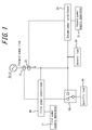
- a dispersed power supply system has, as illustrated in FIG. 1 , a first power supply system including a first power conditioner 10, a first power supply apparatus 11 and a first current sensor 12, a second power supply system including a second power conditioner 20, a second power supply apparatus 21 and a second current sensor 22, a general load 30, a specific load 40 and a switch 50 configured to switch a power supply source to the specific load 40.
- the second power conditioner 20, the second power supply apparatus 21 and the second current sensor 22 correspond respectively to another power conditioner, another power supply apparatus and another current sensor in claims.
- the solid lines connecting each function block represent a wire that carries power.
- the dashed lines connecting each power conditioner and each current sensor represent flow of control signal or information to be communicated. Communications indicated by the dashed lines may be wired communication or wireless communication.
- various schemes including physical layers and logic layers can be adopted.
- a communication by a short range communication scheme such as ZigBee® may be adopted.
- various transmission media such as infrared communication, power line communication (PLC), or the like, may be used.
- a communication protocol such as, for example, ZigBee SEP2.0 (Smart Energy Profile 2.0), ECHONET Lite®, or the like, by which only a logic layer is specified may be operated.
- a communication protocol such as, for example, ZigBee SEP2.0 (Smart Energy Profile 2.0), ECHONET Lite®, or the like, by which only a logic layer is specified may be operated.
- the first power supply apparatus 11 of the first power supply system is a storage battery
- the second power supply apparatus 21 of the second power supply system is a fuel cell.
- the first power supply apparatus 11 storage battery
- the second power supply apparatus 21 fuel cell
- the first current sensor 12 and the second current sensor 22 are installed on a position where the current from the grid is detected as the same forward power flow.
- the value detected by the first current sensor 12 is communicated to the first power conditioner 10.
- the value detected by the second current sensor 22 is communicated to the second power conditioner 20.
- the first forward power flow threshold by which the first power conditioner 10 prevents reverse power flow and the second forward power flow threshold by which the second power conditioner 20 prevents reverse power flow are different values, and each power conditioner does not have information of the forward power flow threshold of the another power conditioner.
- the general load 30 is a load normally used in households, offices, or the like, and is electrical equipment, such as, for example, a television, an air conditioner, a dryer, a vacuum, or the like.
- the specific load 40 is a load used for independent operation, such as during power failure of grid, and is electrical equipment such as, for example, an emergency lighting, or the like.
- the switch 50 is a switch configured to switch a power supply source to the specific load 40 by user operation. As illustrated in the figure, when the switch 50 is set on the side of the first power conditioner 10, it is advantageous in that, during the independent operation, power is supplied automatically from the first power conditioner 10 to the specific load 40 without user operation.
- the first power conditioner 10 adjusts its own first forward power flow threshold, thereby performing control to resolve output difference between power conditioners.
- a conventional output control method in which a forward power flow threshold is not adjusted is explained.
- the forward power flow and the forward power flow threshold are represented in watts (W).
- W watts
- the first forward power flow threshold of the first power conditioner 10 is 22W
- the second forward power flow threshold of the second power conditioner 20 is 30W
- the power consumption of the general load 30 is 100W. Then the influence of the output from the first power conditioner 10 to the specific load 40 is not taken into account.
- first power conditioner 10 and the second power conditioner 20 outputs thereof can respectively be adjusted in the range from zero to the maximum output (e.g. 2.5 kW) of each power supply apparatus.
- the output of the first power conditioner 10, the output of the second power conditioner 20, the first forward power flow threshold, the second forward power flow threshold, and the power from the grid are abbreviated respectively to the "first output,” the “second output,” the “first threshold,” the “second threshold” and the “forward power flow.”
- a processing step of each flow chart is performed by a controller that includes a suitable processor provided in each power conditioner.
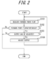
- FIG. 2 is an output control flow of a conventional power conditioner and FIG. 3 is a diagram illustrating output changes by the conventional output control.
- the power (forward power flow) of 30W from the grid and the output of 70W from the second power conditioner 20 are supplied to the general load of 100W.
- the first power conditioner 10 measures the forward power flow by the first current sensor 12 (step S101), and since the forward power flow of 30W is higher than the first forward power flow threshold of 22W (Yes at step S102), can afford to adjust the output of the first power supply apparatus 11 (Yes at step S103), thus increases output by the difference of 8W so that the forward power flow of 30W will be the same value as the first forward power flow threshold of 22W (step S104).
- the second power conditioner 20 measures the forward power flow by the second current sensor 22 (step S101), and since the forward power flow of 22W is lower than the second forward power flow threshold of 30W (Yes at step S102), can afford to adjust the output of the second power supply apparatus 21 (Yes at step S103), thus decreases the difference of 8W so that the forward power flow 22W will be the same value as the second forward power flow threshold of 30W (step S104).
- the first power conditioner 10 increases the output and the second power conditioner 20 decreases the output according to the forward power flow (T3 to T19), and as a result of that, at the final state T20, output (78W) concentrates on the first power conditioner 10 and output difference can occur.
- the output of the second power conditioner 20 is zero, and it is not possible to decrease the output below zero, thus the state where output cannot be adjusted (adjustment disabled state) can occur.
- FIG. 4 is an output control flow of a power conditioner according to the first embodiment of this disclosure
- FIG. 5 is a diagram illustrating output changes by the output control according to the first embodiment.
- the first power conditioner 10 controls the output of the first power supply apparatus 11 so that the forward power flow that is higher than the first forward power flow threshold will be adjusted to the first forward power flow threshold, and then, if the forward power flow is higher than the first forward power flow threshold, increases the first forward power flow threshold.
- the second power conditioner 20 performs the conventional output control illustrated in FIG. 2 .
- the first power conditioner 10 performs, during states T1 to T4 illustrated in FIG. 5 , the conventional output control as with the second power conditioner 20. This is because, as a cause for the forward power flow that is again higher than the first forward power flow threshold after the forward power flow is controlled to be adjusted to the first forward power flow threshold, besides the difference in the forward power flow threshold from the second power conditioner 20, various causes such as decline in the output of the second power conditioner, increase in the power consumption of the general load, or the like, can be considered. Note that, at the time of the initial setup, it is possible to switch to the output control flow according to the present embodiment illustrated in FIG. 4 by setting an administrator or the like.
- the first power conditioner 10 determines, at the time of state T5, that the second forward power flow threshold of the second power conditioner 20 is different from its own first forward power flow threshold based on the periodicity of change of the forward power flow, and switches the processing to the output control flow illustrated in FIG. 4 .
- the above described information on the periodicity of the forward power flow may be obtained by the controller of the first power conditioner 10.
- the first power conditioner 10 measures the forward power flow by the first current sensor 12 (step S201), and since the forward power flow of 30W is higher than the first forward power flow threshold of 22W (Yes at step S202), increases its own first forward power flow threshold to, for example, 26W (step S203).
- the first power conditioner 10 confirms whether output adjustment of the first power supply apparatus 11 is required or not (Yes at step S204). Confirming whether output adjustment is required or not means determining whether output adjustment is required or not to allow the first forward power flow threshold of the first power conditioner 10 to be the same value as the forward power flow value.
- the first power conditioner 10 increases the output by the difference of 4W so that the forward power flow of 30W will be the same value as the first forward power flow threshold of 26W after the increase of threshold (step S205).
- the processing of the second power conditioner 20 at state T6 is the same as the flow illustrated in FIG. 2 .
- a correction value used by the first power conditioner 10 to increase the first forward power flow threshold can be determined based on the difference between the forward power flow and the present first forward power flow threshold. For example, when the difference between the forward power flow and the present first forward power flow threshold is used directly as a correction value, the first power conditioner 10 may be able to immediately set the first forward power flow threshold to the same forward power flow threshold as that of the second power conditioner 20.
- the value obtained by dividing the difference between the forward power flow and the present first forward power flow threshold into two or more is used as a correction value, and the first forward power flow threshold can be increased in stages, thereby allowing the first forward power flow threshold to set to the same forward power flow threshold as that of the second power conditioner 20 while preventing the output fluctuation due to abrupt change in the first forward power flow threshold.
- the first forward power flow threshold is increased in stages, it is not necessary to equalize a correction value at each stage and, for example, correction values in the former stage may be set high and those in the latter stage may gradually be decreased, thereby immediately allowing the first forward power flow threshold to be close to the second forward power flow threshold of the second power conditioner 20.
- the same forward power flow threshold can be set more precisely.
- the first power conditioner 10 measures the forward power flow by the first current sensor 12 (step S201), and since the forward power flow of 30W is higher than the first forward power flow threshold of 26W (Yes at step S202), increases its own first forward power flow threshold to, for example, 30W (step S203). In this case, since the forward power flow of 30W is equal to the first forward power flow threshold of 30W as a result of the increase in the threshold, output adjustment is not necessary (No at step S204).
- the first forward power flow threshold of the first power conditioner 10 and the second forward power flow threshold of the second power conditioner 20 are both 30W, which is equal to the forward power flow, thus the output of the first power conditioner 10 and the output of the second power conditioner 20 can be stabilized.
- the first power conditioner 10 increases the first forward power flow threshold, then at state T9, measures the forward power flow by the first current sensor 12 (step S201) and detects that the forward power flow of 30W is equal to the first forward power flow threshold of 30W (No at step S202).
- the first power conditioner 10 may stop increasing the forward power flow threshold and switch from the output control flow according to the present embodiment to the conventional output control flow illustrated in FIG. 2 .
- the first power conditioner 10 and the second power conditioner 20 can appropriately perform desired output.
- the first power conditioner 10 increases the first forward power flow threshold if the forward power flow is higher than the first forward power flow threshold after controlling the output of the first power supply apparatus 11 so that the forward power flow that is higher than the first forward power flow threshold is adjusted to the first forward power flow threshold.
- forward power flow thresholds of each power conditioner are different from each other, output difference between power supply systems can be resolved.
- output concentration on the power supply system having a smaller forward power flow threshold can be prevented, and the power supply system having a higher forward power flow threshold can be operated appropriately.
- the first power conditioner 10 stops increasing the forward power flow threshold when the forward power flow is equal to the first forward power flow threshold after increasing the first forward power flow threshold.
- the forward power flow thresholds between dispersed power supply systems can be equalized, thereby allowing the output of each power supply system to be stabilized.
- FIG. 6 is an output control flow chart of the power conditioner according to a second embodiment of this disclosure
- FIG. 7 is a diagram illustrating output changes by the output control according to the second embodiment.
- the first power conditioner 10 controls the output of the first power supply apparatus 11 to adjust the forward power flow that is higher than the first forward power flow threshold to the first forward power flow threshold, and then, if the forward power flow is higher than the first forward power flow threshold, increases the first forward power flow threshold. Furthermore, the first power conditioner 10 increases the first forward power flow threshold, and then, if the forward power flow is lower than the first forward power flow threshold, decreases the first forward power flow threshold.
- the second power conditioner 20 performs the conventional output control illustrated in FIG. 2 .
- the first power conditioner 10 performs the conventional output control in the same manner as the second power conditioner 20.
- the first power conditioner 10 determines, at state T5, that the second forward power flow threshold of the second power conditioner 20 is different from its own first forward power flow threshold based on the periodicity of the change of the forward power flow, and switches the processing to the output control flow according to the present embodiment illustrated in FIG. 6 .
- the first power conditioner 10 measures the forward power flow by the first current sensor 12 (step S301), and since the forward power flow of 30W is higher than the first forward power flow threshold of 22W (Yes at step S302), increases its own first forward power flow threshold to, for example, 28W (step S303).
- the first power conditioner 10 confirms whether output adjustment of the first power supply apparatus 11 is required or not (Yes at step S304), and increases the output by the difference of 2W so that the forward power flow of 30W will be the same value as the first forward power flow threshold of 28W after the increase of threshold (step S305).
- the processing of the second power conditioner 20 at state T6 is the same as the flow illustrated in FIG. 2 .
- the first power conditioner 10 measures the forward power flow by the first current sensor 12 (step S301), and since the forward power flow of 30W is higher than the first forward power flow threshold of 28W (Yes at step S302), increases its own first forward power flow threshold to, for example, 34W (step S303). Furthermore, the first power conditioner 10 confirms whether output adjustment of the first power supply apparatus 11 is required or not (Yes at step S304), and decreases the output by the difference of 4W so that the forward power flow of 30W will be the same value as the first forward power flow threshold of 34W after the increase of threshold (step S305).
- the processing of the second power conditioner 20 at state T8 is the same as the flow illustrated in FIG. 2 .
- the first power conditioner 10 measures the forward power flow by the first current sensor 12 (step S301), and since the forward power flow of 30W is lower than the first forward power flow threshold of 34W (No at step S302, Yes at step S306), decreases its own first forward power flow threshold to, for example, 32W (step S307). Furthermore, the first power conditioner 10 confirms whether output adjustment of the first power supply apparatus 11 is required or not (Yes at step S304), and decreases the output by the difference of 2W, so that the forward power flow of 30W will be the same value as the first forward power flow threshold of 32W after the decrease of threshold (step S305).
- the processing of the second power conditioner 20 at state T10 is the same as the flow illustrated in FIG. 2 .
- the first power conditioner 10 measures the forward power flow by the first current sensor 12 (step S301), and since the forward power flow of 30W is lower than the first forward power flow threshold of 32W (No at step S302, Yes at step S306), decreases its own first forward power flow threshold to, for example, 30W (step S307). In this case, the first power conditioner 10 requires no output adjustment since the forward power flow of 30W is equal to the first forward power flow threshold of 30W after the increase of threshold (No at step S304).
- the first forward power flow threshold of the first power conditioner 10 and the second forward power flow threshold of the second power conditioner 20 are both 30W, which is equal to the forward power flow, thus the output of the first power conditioner 10 and the output of the second power conditioner 20 can be stabilized.
- the first power conditioner 10 measures, for example, after decreasing the first forward power flow threshold, the forward power flow by the first current sensor 12 (step S301) at state T13, and detects that the forward power flow of 30W is equal to the first forward power flow threshold of 30W (No at step S302 and No at step S306). In this case, the first power conditioner 10 may stop decreasing the forward power flow threshold and switch from the output control flow according to the present embodiment to the conventional output control flow illustrated in FIG. 2 . Furthermore, after the output is stabilized, the first power conditioner 10 and the second power conditioner 20 can appropriately perform desired output.
- the first power conditioner 10 controls the output of the first power supply apparatus 11 so that the forward power flow that is higher than the first forward power flow threshold will be adjusted to the first forward power flow threshold, and then, if the forward power flow is higher than the first forward power flow threshold, increases the first forward power flow threshold. Furthermore, the first power conditioner 10 increases the first forward power flow threshold, and then, if the forward power flow is lower than the first forward power flow threshold, decreases the first forward power flow threshold. Thus, even if the lower forward power flow threshold is increased and the increased threshold exceeds the higher forward power flow threshold, the forward power flow threshold of each dispersed power supply system can be appropriately set equal. That is, output difference between each dispersed power supply system is suppressed, thereby allowing each power supply system to be operated in a stable manner.
- the first power conditioner 10 controls the output of the first power supply apparatus 11 until the forward power flow is equal to the first forward power flow threshold, and then, may store the forward power flow value as a first forward power flow threshold. If the first power conditioner 10 operates, at the time of next startup, by replacing the forward power flow threshold with the stored first forward power flow threshold, the operation for increasing or decreasing the forward power flow threshold for equalization may be omitted from the second time on. Thus, effects such as decrease in the consumed power relating to increase/decrease in the forward power flow and to control (calculation) of determination of threshold, and stabilized output of the first power conditioner and the second power conditioner can be obtained. Note that, in consideration of errors or the like of the equipment, operation for increasing/decreasing the forward power flow threshold for equalization may be performed again by resetting the previous data after a lapse of a predetermined period of time.
- the first power conditioner 10 may, after equalizing the forward power flow thresholds between the dispersed power supply systems, increase or decrease the first forward power flow threshold of the first power conditioner 10 relative to the reference threshold by using the second forward power flow threshold for preventing reverse power flow of the second power conditioner 20 as a reference threshold. This allows the output from only one of either the first power conditioner 10 or the second power conditioner 20.
- the first power supply system and the second power supply system have been described as a storage battery system and a fuel cell system, respectively, this disclosure is not limited thereto, and is applicable to dispersed power supply systems that include any kinds of power supply system having various forward power flow thresholds different from each other.
- this disclosure can be applied to, for example, a dispersed power supply system including two electricity storage systems having forward power flow thresholds different from each other.
Landscapes
- Engineering & Computer Science (AREA)
- Power Engineering (AREA)
- Supply And Distribution Of Alternating Current (AREA)
Abstract
Description
- This disclosure relates to a dispersed power supply system and a power conditioner.
- There exists a dispersed power supply system in which a natural energy type power supply system such as a solar cell, or the like, and a non-natural energy type power supply system such as a storage battery, a fuel battery, or the like, are interconnected to the same commercial power grid (hereinafter appropriately abbreviated to a grid) (for example, see PTL 1). Furthermore, a plurality of non-natural energy type power supply systems can be interconnected to the same grid to form a dispersed power supply system. Each power supply system can perform an interconnection operation in which the alternating current power is output through a grid interconnection and an independent operation in which the alternating current power is output independently of the grid in the event of a power failure of the grid.
- In the case of a non-natural energy type power supply system, unlike a natural energy type power supply system such as solar power generation, permission from a power company is separately required to sell electric power to the grid. Note that, under the present regulations in Japan, it is specified that the power obtained from a non-natural energy type power supply system should be controlled so as not to be sold. Thus, in order to prevent reverse power flow to the grid (current in the direction of selling power), a current sensor is connected to each power conditioner of a non-natural energy type power supply system to detect current between the power supply system and the grid. In order to prevent selling power to the grid, each power conditioner controls so that a predetermined forward power (current in the direction of buying power) always flows in the current sensor. If the forward power flow is lower than a predetermined threshold (forward power flow threshold) during power supply to a load, each power conditioner decreases its own output to increase the forward power flow from the grid. In addition, if the forward power flow is higher than the forward power flow threshold, each power conditioner increases its own output to decrease the forward power flow from the grid.
- PTL 1: JPH1146458 (A)
- When a plurality of power conditioners of a non-natural energy type power supply system is interconnected to the same grid, there is a need to install respective current sensors so that an output of a power conditioner will not be detected as a reverse power flow by a current sensor of another power conditioner. Thus, each of current sensors is installed on the grid side from a branch point to which each of power conditioners is connected, and thus detects the power from the grid as the same power (forward power flow).
- Here, with respect to forward power flow thresholds of a plurality of power conditioners, different values are set depending on, for example, a type of a product, a manufacturer, or the like, and thresholds may not be discriminated from each other. When forward power flow thresholds are different from each other, only a specific power conditioner may output and other power conditioners may not output. As described above, each current sensor detects the same forward power flow, and allows a power conditioner whose forward power flow threshold is higher than the forward power flow to decrease the output, and allows a power conditioner whose forward power flow threshold is lower than the forward power flow to increase the output. Thus, as a result, output is concentrated on a power conditioner whose forward power flow threshold is low, and a power conditioner whose forward power flow threshold is high stops outputting. If such situation continues, it may cause harmful effects, such as a drastic decrease in SOH (State of Health) of a power supply apparatus on which output is concentrated, compared to the other power supply apparatus.
- It would therefore be helpful to provide a dispersed power supply system that has a plurality of non-natural energy type power supply systems, and when forward power flow thresholds of each power conditioner are different from each other, can dissolve output difference between each power supply system, and a power conditioner.
- A dispersed power supply system according to one embodiment of this disclosure includes:
- a power conditioner configured to control an output of a power supply apparatus;
- a current sensor connected to the power conditioner;
- another power conditioner configured to control an output of another power supply apparatus; and
- another current sensor connected to the another power conditioner,
- wherein the current sensor and the another current sensor are installed on a position where current from a grid is detected as the same forward power flow; and
- when a forward power flow threshold for preventing a reverse power flow of the power conditioner is different from another forward power flow threshold for preventing reverse power flow of the another power conditioner,
- the power conditioner controls the output of the power supply apparatus to adjust the forward power flow that is higher than the forward power flow threshold to the forward power flow threshold, and then, if the forward power flow is higher than the forward power flow threshold when the another power conditioner controls the output of the another power supply apparatus based on the another forward power flow threshold, increases the forward power flow threshold.
- A power conditioner according to one embodiment of this disclosure is a power conditioner that is connected to a current sensor to control an output of a power supply apparatus and is interconnected to the same grid as that of another power conditioner configured to control an output of another power supply apparatus,
wherein the current sensor and a current sensor of another power conditioner are installed on a position where a current from the grid is detected as the same forward power flow; and
the power conditioner has a controller configured to control, when a forward power flow threshold for preventing a reverse power flow of the power conditioner is different from another forward power flow threshold for preventing a reverse power flow of the another power conditioner, the output of the power supply apparatus to adjust the forward power flow that is higher than the forward power flow threshold to the forward power flow threshold, and then, if the forward power flow is higher than the forward power flow threshold when the another power conditioner controls the output of the another power supply apparatus based on the another forward power flow threshold, to increase the forward power flow threshold. - In the disclosed dispersed power supply system and power conditioner, a plurality of non-natural energy type power supply systems are provided, and when forward power flow thresholds of each power conditioner are different from each other, output difference between power supply systems can be dissolved.
- In the accompanying drawings:
-
FIG. 1 is a diagram illustrating a configuration of a dispersed power supply system according to one embodiment of this disclosure; -
FIG. 2 is an output control flow chart of a conventional power conditioner; -
FIG. 3 is a diagram illustrating output changes by a conventional output control; -
FIG. 4 is an output control flow chart according to a first embodiment of this disclosure; -
FIG. 5 is a diagram illustrating output changes by output control according to the first embodiment; -
FIG. 6 is an output control flow chart according to a second embodiment of this disclosure; and -
FIG. 7 is a diagram illustrating output changes by output control according to the second embodiment. - Detailed description of embodiments of this disclosure is given below with reference to drawings.
- A dispersed power supply system according to one embodiment of this disclosure has, as illustrated in
FIG. 1 , a first power supply system including afirst power conditioner 10, a firstpower supply apparatus 11 and a firstcurrent sensor 12, a second power supply system including asecond power conditioner 20, a secondpower supply apparatus 21 and a secondcurrent sensor 22, ageneral load 30, aspecific load 40 and aswitch 50 configured to switch a power supply source to thespecific load 40. Here, thesecond power conditioner 20, the secondpower supply apparatus 21 and the secondcurrent sensor 22 correspond respectively to another power conditioner, another power supply apparatus and another current sensor in claims. InFIG. 1 , the solid lines connecting each function block represent a wire that carries power. Furthermore, inFIG.1 , the dashed lines connecting each power conditioner and each current sensor represent flow of control signal or information to be communicated. Communications indicated by the dashed lines may be wired communication or wireless communication. For communication of control signal and information, various schemes including physical layers and logic layers can be adopted. For example, a communication by a short range communication scheme such as ZigBee® may be adopted. Furthermore, various transmission media such as infrared communication, power line communication (PLC), or the like, may be used. In addition, on a physical layer that is suitable for respective communications, various protocols, such as, for example, a communication protocol, such as, for example, ZigBee SEP2.0 (Smart Energy Profile 2.0), ECHONET Lite®, or the like, by which only a logic layer is specified may be operated. - In the present embodiment, the first
power supply apparatus 11 of the first power supply system is a storage battery, and the secondpower supply apparatus 21 of the second power supply system is a fuel cell. The first power supply apparatus 11 (storage battery) can accumulate the power supplied from the grid or the power generated by a solar cell (not illustrated) or the like. The second power supply apparatus 21 (fuel cell) generates power through an electrochemical reaction of gas such as hydrogen and oxygen supplied from outside. As illustrated in the figure, the firstcurrent sensor 12 and the secondcurrent sensor 22 are installed on a position where the current from the grid is detected as the same forward power flow. The value detected by the firstcurrent sensor 12 is communicated to thefirst power conditioner 10. Furthermore, the value detected by the secondcurrent sensor 22 is communicated to thesecond power conditioner 20. Moreover, the first forward power flow threshold by which thefirst power conditioner 10 prevents reverse power flow and the second forward power flow threshold by which thesecond power conditioner 20 prevents reverse power flow are different values, and each power conditioner does not have information of the forward power flow threshold of the another power conditioner. - The
general load 30 is a load normally used in households, offices, or the like, and is electrical equipment, such as, for example, a television, an air conditioner, a dryer, a vacuum, or the like. Thespecific load 40 is a load used for independent operation, such as during power failure of grid, and is electrical equipment such as, for example, an emergency lighting, or the like. Theswitch 50 is a switch configured to switch a power supply source to thespecific load 40 by user operation. As illustrated in the figure, when theswitch 50 is set on the side of thefirst power conditioner 10, it is advantageous in that, during the independent operation, power is supplied automatically from thefirst power conditioner 10 to thespecific load 40 without user operation. - In the present embodiment, the
first power conditioner 10 adjusts its own first forward power flow threshold, thereby performing control to resolve output difference between power conditioners. First of all, before explaining the output control method according to the embodiment of this disclosure, a conventional output control method in which a forward power flow threshold is not adjusted is explained. Note that, hereinafter, for simplification of explanation, the forward power flow and the forward power flow threshold are represented in watts (W). However, a person skilled in the art may appropriately measure and convert the current/power. The first forward power flow threshold of thefirst power conditioner 10 is 22W, the second forward power flow threshold of thesecond power conditioner 20 is 30W, and the power consumption of thegeneral load 30 is 100W. Then the influence of the output from thefirst power conditioner 10 to thespecific load 40 is not taken into account. For thefirst power conditioner 10 and thesecond power conditioner 20, outputs thereof can respectively be adjusted in the range from zero to the maximum output (e.g. 2.5 kW) of each power supply apparatus. Note that, in each diagram, the output of thefirst power conditioner 10, the output of thesecond power conditioner 20, the first forward power flow threshold, the second forward power flow threshold, and the power from the grid are abbreviated respectively to the "first output," the "second output," the "first threshold," the "second threshold" and the "forward power flow." Furthermore, a processing step of each flow chart is performed by a controller that includes a suitable processor provided in each power conditioner. -
FIG. 2 is an output control flow of a conventional power conditioner andFIG. 3 is a diagram illustrating output changes by the conventional output control. At the initial state T1, the power (forward power flow) of 30W from the grid and the output of 70W from thesecond power conditioner 20 are supplied to the general load of 100W. At this time, thefirst power conditioner 10 measures the forward power flow by the first current sensor 12 (step S101), and since the forward power flow of 30W is higher than the first forward power flow threshold of 22W (Yes at step S102), can afford to adjust the output of the first power supply apparatus 11 (Yes at step S103), thus increases output by the difference of 8W so that the forward power flow of 30W will be the same value as the first forward power flow threshold of 22W (step S104). On the other hand, at state T2, thesecond power conditioner 20 measures the forward power flow by the second current sensor 22 (step S101), and since the forward power flow of 22W is lower than the second forward power flow threshold of 30W (Yes at step S102), can afford to adjust the output of the second power supply apparatus 21 (Yes at step S103), thus decreases the difference of 8W so that the forward power flow 22W will be the same value as the second forward power flow threshold of 30W (step S104). In this manner, thefirst power conditioner 10 increases the output and thesecond power conditioner 20 decreases the output according to the forward power flow (T3 to T19), and as a result of that, at the final state T20, output (78W) concentrates on thefirst power conditioner 10 and output difference can occur. At this final state T20, the output of thesecond power conditioner 20 is zero, and it is not possible to decrease the output below zero, thus the state where output cannot be adjusted (adjustment disabled state) can occur. -
FIG. 4 is an output control flow of a power conditioner according to the first embodiment of this disclosure, andFIG. 5 is a diagram illustrating output changes by the output control according to the first embodiment. In the output control according to the first embodiment, thefirst power conditioner 10 controls the output of the firstpower supply apparatus 11 so that the forward power flow that is higher than the first forward power flow threshold will be adjusted to the first forward power flow threshold, and then, if the forward power flow is higher than the first forward power flow threshold, increases the first forward power flow threshold. Note that thesecond power conditioner 20 performs the conventional output control illustrated inFIG. 2 . - The
first power conditioner 10 performs, during states T1 to T4 illustrated inFIG. 5 , the conventional output control as with thesecond power conditioner 20. This is because, as a cause for the forward power flow that is again higher than the first forward power flow threshold after the forward power flow is controlled to be adjusted to the first forward power flow threshold, besides the difference in the forward power flow threshold from thesecond power conditioner 20, various causes such as decline in the output of the second power conditioner, increase in the power consumption of the general load, or the like, can be considered. Note that, at the time of the initial setup, it is possible to switch to the output control flow according to the present embodiment illustrated inFIG. 4 by setting an administrator or the like. - The
first power conditioner 10 determines, at the time of state T5, that the second forward power flow threshold of thesecond power conditioner 20 is different from its own first forward power flow threshold based on the periodicity of change of the forward power flow, and switches the processing to the output control flow illustrated inFIG. 4 . Note that, the above described information on the periodicity of the forward power flow may be obtained by the controller of thefirst power conditioner 10. Thefirst power conditioner 10 measures the forward power flow by the first current sensor 12 (step S201), and since the forward power flow of 30W is higher than the first forward power flow threshold of 22W (Yes at step S202), increases its own first forward power flow threshold to, for example, 26W (step S203). Furthermore, thefirst power conditioner 10 confirms whether output adjustment of the firstpower supply apparatus 11 is required or not (Yes at step S204). Confirming whether output adjustment is required or not means determining whether output adjustment is required or not to allow the first forward power flow threshold of thefirst power conditioner 10 to be the same value as the forward power flow value. Next, thefirst power conditioner 10 increases the output by the difference of 4W so that the forward power flow of 30W will be the same value as the first forward power flow threshold of 26W after the increase of threshold (step S205). The processing of thesecond power conditioner 20 at state T6 is the same as the flow illustrated inFIG. 2 . - Here, a correction value used by the
first power conditioner 10 to increase the first forward power flow threshold can be determined based on the difference between the forward power flow and the present first forward power flow threshold. For example, when the difference between the forward power flow and the present first forward power flow threshold is used directly as a correction value, thefirst power conditioner 10 may be able to immediately set the first forward power flow threshold to the same forward power flow threshold as that of thesecond power conditioner 20. Furthermore, the value obtained by dividing the difference between the forward power flow and the present first forward power flow threshold into two or more is used as a correction value, and the first forward power flow threshold can be increased in stages, thereby allowing the first forward power flow threshold to set to the same forward power flow threshold as that of thesecond power conditioner 20 while preventing the output fluctuation due to abrupt change in the first forward power flow threshold. Note that, when the first forward power flow threshold is increased in stages, it is not necessary to equalize a correction value at each stage and, for example, correction values in the former stage may be set high and those in the latter stage may gradually be decreased, thereby immediately allowing the first forward power flow threshold to be close to the second forward power flow threshold of thesecond power conditioner 20. Thus the same forward power flow threshold can be set more precisely. - At state T7, the
first power conditioner 10 measures the forward power flow by the first current sensor 12 (step S201), and since the forward power flow of 30W is higher than the first forward power flow threshold of 26W (Yes at step S202), increases its own first forward power flow threshold to, for example, 30W (step S203). In this case, since the forward power flow of 30W is equal to the first forward power flow threshold of 30W as a result of the increase in the threshold, output adjustment is not necessary (No at step S204). - At and after state T8, the first forward power flow threshold of the
first power conditioner 10 and the second forward power flow threshold of thesecond power conditioner 20 are both 30W, which is equal to the forward power flow, thus the output of thefirst power conditioner 10 and the output of thesecond power conditioner 20 can be stabilized. For example, thefirst power conditioner 10 increases the first forward power flow threshold, then at state T9, measures the forward power flow by the first current sensor 12 (step S201) and detects that the forward power flow of 30W is equal to the first forward power flow threshold of 30W (No at step S202). In this case, thefirst power conditioner 10 may stop increasing the forward power flow threshold and switch from the output control flow according to the present embodiment to the conventional output control flow illustrated inFIG. 2 . Furthermore, after the output is stabilized, thefirst power conditioner 10 and thesecond power conditioner 20 can appropriately perform desired output. - In this manner, according to the present embodiment, the
first power conditioner 10 increases the first forward power flow threshold if the forward power flow is higher than the first forward power flow threshold after controlling the output of the firstpower supply apparatus 11 so that the forward power flow that is higher than the first forward power flow threshold is adjusted to the first forward power flow threshold. Thus, when forward power flow thresholds of each power conditioner are different from each other, output difference between power supply systems can be resolved. In particular, output concentration on the power supply system having a smaller forward power flow threshold can be prevented, and the power supply system having a higher forward power flow threshold can be operated appropriately. - In addition, the
first power conditioner 10 stops increasing the forward power flow threshold when the forward power flow is equal to the first forward power flow threshold after increasing the first forward power flow threshold. Thus, the forward power flow thresholds between dispersed power supply systems can be equalized, thereby allowing the output of each power supply system to be stabilized. -
FIG. 6 is an output control flow chart of the power conditioner according to a second embodiment of this disclosure, andFIG. 7 is a diagram illustrating output changes by the output control according to the second embodiment. In the output control according to the second embodiment, thefirst power conditioner 10 controls the output of the firstpower supply apparatus 11 to adjust the forward power flow that is higher than the first forward power flow threshold to the first forward power flow threshold, and then, if the forward power flow is higher than the first forward power flow threshold, increases the first forward power flow threshold. Furthermore, thefirst power conditioner 10 increases the first forward power flow threshold, and then, if the forward power flow is lower than the first forward power flow threshold, decreases the first forward power flow threshold. Note that thesecond power conditioner 20 performs the conventional output control illustrated inFIG. 2 . In addition, as in the case of the first embodiment, during states of T1 to T5, thefirst power conditioner 10 performs the conventional output control in the same manner as thesecond power conditioner 20. - The
first power conditioner 10 determines, at state T5, that the second forward power flow threshold of thesecond power conditioner 20 is different from its own first forward power flow threshold based on the periodicity of the change of the forward power flow, and switches the processing to the output control flow according to the present embodiment illustrated inFIG. 6 . Thefirst power conditioner 10 measures the forward power flow by the first current sensor 12 (step S301), and since the forward power flow of 30W is higher than the first forward power flow threshold of 22W (Yes at step S302), increases its own first forward power flow threshold to, for example, 28W (step S303). Furthermore, thefirst power conditioner 10 confirms whether output adjustment of the firstpower supply apparatus 11 is required or not (Yes at step S304), and increases the output by the difference of 2W so that the forward power flow of 30W will be the same value as the first forward power flow threshold of 28W after the increase of threshold (step S305). The processing of thesecond power conditioner 20 at state T6 is the same as the flow illustrated inFIG. 2 . - At state T7, the
first power conditioner 10 measures the forward power flow by the first current sensor 12 (step S301), and since the forward power flow of 30W is higher than the first forward power flow threshold of 28W (Yes at step S302), increases its own first forward power flow threshold to, for example, 34W (step S303). Furthermore, thefirst power conditioner 10 confirms whether output adjustment of the firstpower supply apparatus 11 is required or not (Yes at step S304), and decreases the output by the difference of 4W so that the forward power flow of 30W will be the same value as the first forward power flow threshold of 34W after the increase of threshold (step S305). The processing of thesecond power conditioner 20 at state T8 is the same as the flow illustrated inFIG. 2 . - At the time of state T9, the
first power conditioner 10 measures the forward power flow by the first current sensor 12 (step S301), and since the forward power flow of 30W is lower than the first forward power flow threshold of 34W (No at step S302, Yes at step S306), decreases its own first forward power flow threshold to, for example, 32W (step S307). Furthermore, thefirst power conditioner 10 confirms whether output adjustment of the firstpower supply apparatus 11 is required or not (Yes at step S304), and decreases the output by the difference of 2W, so that the forward power flow of 30W will be the same value as the first forward power flow threshold of 32W after the decrease of threshold (step S305). The processing of thesecond power conditioner 20 at state T10 is the same as the flow illustrated inFIG. 2 . - At the time of state T11, the
first power conditioner 10 measures the forward power flow by the first current sensor 12 (step S301), and since the forward power flow of 30W is lower than the first forward power flow threshold of 32W (No at step S302, Yes at step S306), decreases its own first forward power flow threshold to, for example, 30W (step S307). In this case, thefirst power conditioner 10 requires no output adjustment since the forward power flow of 30W is equal to the first forward power flow threshold of 30W after the increase of threshold (No at step S304). - At and after state T12, the first forward power flow threshold of the
first power conditioner 10 and the second forward power flow threshold of thesecond power conditioner 20 are both 30W, which is equal to the forward power flow, thus the output of thefirst power conditioner 10 and the output of thesecond power conditioner 20 can be stabilized. Thefirst power conditioner 10 measures, for example, after decreasing the first forward power flow threshold, the forward power flow by the first current sensor 12 (step S301) at state T13, and detects that the forward power flow of 30W is equal to the first forward power flow threshold of 30W (No at step S302 and No at step S306). In this case, thefirst power conditioner 10 may stop decreasing the forward power flow threshold and switch from the output control flow according to the present embodiment to the conventional output control flow illustrated inFIG. 2 . Furthermore, after the output is stabilized, thefirst power conditioner 10 and thesecond power conditioner 20 can appropriately perform desired output. - In this manner, according to the present embodiment, the
first power conditioner 10 controls the output of the firstpower supply apparatus 11 so that the forward power flow that is higher than the first forward power flow threshold will be adjusted to the first forward power flow threshold, and then, if the forward power flow is higher than the first forward power flow threshold, increases the first forward power flow threshold. Furthermore, thefirst power conditioner 10 increases the first forward power flow threshold, and then, if the forward power flow is lower than the first forward power flow threshold, decreases the first forward power flow threshold. Thus, even if the lower forward power flow threshold is increased and the increased threshold exceeds the higher forward power flow threshold, the forward power flow threshold of each dispersed power supply system can be appropriately set equal. That is, output difference between each dispersed power supply system is suppressed, thereby allowing each power supply system to be operated in a stable manner. - In addition, the
first power conditioner 10 controls the output of the firstpower supply apparatus 11 until the forward power flow is equal to the first forward power flow threshold, and then, may store the forward power flow value as a first forward power flow threshold. If thefirst power conditioner 10 operates, at the time of next startup, by replacing the forward power flow threshold with the stored first forward power flow threshold, the operation for increasing or decreasing the forward power flow threshold for equalization may be omitted from the second time on. Thus, effects such as decrease in the consumed power relating to increase/decrease in the forward power flow and to control (calculation) of determination of threshold, and stabilized output of the first power conditioner and the second power conditioner can be obtained. Note that, in consideration of errors or the like of the equipment, operation for increasing/decreasing the forward power flow threshold for equalization may be performed again by resetting the previous data after a lapse of a predetermined period of time. - Furthermore, the
first power conditioner 10 may, after equalizing the forward power flow thresholds between the dispersed power supply systems, increase or decrease the first forward power flow threshold of thefirst power conditioner 10 relative to the reference threshold by using the second forward power flow threshold for preventing reverse power flow of thesecond power conditioner 20 as a reference threshold. This allows the output from only one of either thefirst power conditioner 10 or thesecond power conditioner 20. - Although this disclosure has been described based on various drawings and embodiments, it is to be noted that a person skilled in the art may easily perform various changes and modifications based on this disclosure. Therefore, such changes and modifications are to be understood as included within the scope of this disclosure. For example, the functions or the like included in each function and each step may be reordered in any logically consistent manner, and functions and steps may be combined into one or divided.
- For example, in the above described embodiments, although the first power supply system and the second power supply system have been described as a storage battery system and a fuel cell system, respectively, this disclosure is not limited thereto, and is applicable to dispersed power supply systems that include any kinds of power supply system having various forward power flow thresholds different from each other. For example, it is apparent that this disclosure can be applied to, for example, a dispersed power supply system including two electricity storage systems having forward power flow thresholds different from each other.
-
- 10 First power conditioner
- 11 First power supply apparatus
- 12 First current sensor
- 20 Second power conditioner (another power conditioner)
- 21 Second power supply apparatus (another power supply apparatus)
- 22 Second current sensor (another current sensor) 30 General load
- 40 Specific load
- 50 Switch
Claims (6)
- A dispersed power supply system, comprising,
a power conditioner configured to control an output of a power supply apparatus;
a current sensor connected to the power conditioner;
another power conditioner configured to control an output of another power supply apparatus; and
another current sensor connected to the another power conditioner,
wherein the current sensor and the another current sensor are installed on a position where current from a grid is detected as the same forward power flow; and
when a forward power flow threshold for preventing a reverse power flow of the power conditioner is lower than another forward power flow threshold for preventing a reverse power flow of the another power conditioner,
the power conditioner controls the output of the power supply apparatus to adjust the forward power flow that is higher than the forward power flow threshold to the forward power flow threshold, and then, if the forward power flow is higher than the forward power flow threshold when the another power conditioner controls the output of the another power supply apparatus based on the another forward power flow threshold, increases the forward power flow threshold. - The dispersed power supply system according to claim 1, wherein the power conditioner increases the forward power flow threshold, and then, if the forward power flow is equal to the forward power flow threshold, stops increasing the forward power flow threshold.
- The dispersed power supply system according to claim 1 or 2, wherein the power conditioner increases the forward power flow threshold, and then, if the forward power flow is lower than the forward power flow threshold, decreases the forward power flow threshold.
- A power conditioner that is connected to a current sensor to control an output of a power supply apparatus and is interconnected to the same grid as that of another power conditioner configured to control an output of another power supply apparatus,
wherein the current sensor and another current sensor of the another power conditioner are installed on a position where a current from the grid is detected as the same forward power flow: and
the power conditioner comprising a controller configured to control, when a forward power flow threshold for preventing a reverse power flow of the power conditioner is lower than another forward power flow threshold for preventing a reverse power flow of the another power conditioner, the output of the power supply apparatus to adjust the forward power flow that is higher than the forward power flow threshold to the forward power flow threshold, and then, if the forward power flow is higher than the forward power flow threshold when the another power conditioner controls the output of the another power supply apparatus based on the another forward power flow threshold, to increase the forward power flow threshold. - The power conditioner according to claim 4, wherein the controller increases the forward power flow threshold, and then, if the forward power flow is equal to the forward power flow threshold, stops increasing the forward power flow threshold.
- The power conditioner according to claim 4 or 5, wherein the controller increases the forward power flow threshold, and then, if the forward power flow is lower than the forward power flow threshold, decreases the forward power flow threshold.
Applications Claiming Priority (2)
| Application Number | Priority Date | Filing Date | Title |
|---|---|---|---|
| JP2013179971 | 2013-08-30 | ||
| PCT/JP2014/004409 WO2015029431A1 (en) | 2013-08-30 | 2014-08-27 | Distributed power supply system and power conditioner |
Publications (3)
| Publication Number | Publication Date |
|---|---|
| EP3041109A1 true EP3041109A1 (en) | 2016-07-06 |
| EP3041109A4 EP3041109A4 (en) | 2017-04-26 |
| EP3041109B1 EP3041109B1 (en) | 2022-06-29 |
Family
ID=52586020
Family Applications (1)
| Application Number | Title | Priority Date | Filing Date |
|---|---|---|---|
| EP14839163.4A Not-in-force EP3041109B1 (en) | 2013-08-30 | 2014-08-27 | Distributed power supply system and power conditioner |
Country Status (4)
| Country | Link |
|---|---|
| US (1) | US10079491B2 (en) |
| EP (1) | EP3041109B1 (en) |
| JP (1) | JP5781257B2 (en) |
| WO (1) | WO2015029431A1 (en) |
Cited By (4)
| Publication number | Priority date | Publication date | Assignee | Title |
|---|---|---|---|---|
| CN106026104A (en) * | 2016-07-14 | 2016-10-12 | 嘉兴国电通新能源科技有限公司 | Power system optimal power flow control method based on penalty dual decomposition technology |
| CN106159955A (en) * | 2016-07-14 | 2016-11-23 | 嘉兴国电通新能源科技有限公司 | Based on the power system distributed optimal power flow method punishing Duality Decomposition continuously |
| CN106549419A (en) * | 2016-12-07 | 2017-03-29 | 国网重庆市电力公司电力科学研究院 | Independent microgrid system method for designing based on universal gravitation algorithm |
| CN106571643A (en) * | 2016-10-20 | 2017-04-19 | 北京科诺伟业科技股份有限公司 | Optical storage microgrid system control method |
Families Citing this family (7)
| Publication number | Priority date | Publication date | Assignee | Title |
|---|---|---|---|---|
| JP5781257B2 (en) | 2013-08-30 | 2015-09-16 | 京セラ株式会社 | Distributed power system, power conditioner |
| JP6572313B2 (en) * | 2015-08-28 | 2019-09-04 | 京セラ株式会社 | Communication device, management server, and communication method |
| AU2017226244B2 (en) * | 2016-03-02 | 2021-12-09 | Daihen Corporation | Electric power system |
| US10396652B1 (en) * | 2018-04-27 | 2019-08-27 | Hewlett Packard Enterprise Development Lp | Controlled power adjustments |
| EP3627433B1 (en) * | 2018-09-19 | 2021-11-24 | Hitachi Energy Switzerland AG | Resiliency determination in a microgrid |
| WO2023223434A1 (en) * | 2022-05-17 | 2023-11-23 | オムロン株式会社 | Power feed system, full load distribution board, power feed device, power feed control method for power feed device, power feed path, power conversion device, and connection method |
| JP2023181752A (en) * | 2022-06-13 | 2023-12-25 | オムロン株式会社 | Control method and program for power supply system and power supply control device |
Family Cites Families (9)
| Publication number | Priority date | Publication date | Assignee | Title |
|---|---|---|---|---|
| JPH1146458A (en) | 1997-07-08 | 1999-02-16 | Seinan Sogo Kaihatsu Kk | Solar power generating system |
| CN100394665C (en) | 2001-02-16 | 2008-06-11 | 洋马株式会社 | Electric power system having generator driven by engine |
| JP4236389B2 (en) * | 2001-03-22 | 2009-03-11 | 大阪瓦斯株式会社 | Power control method, power control system, control device, and computer program |
| JPWO2008041311A1 (en) * | 2006-10-02 | 2010-02-04 | 大多喜ガス株式会社 | Hybrid power generation system |
| CN102067408A (en) | 2008-06-27 | 2011-05-18 | 夏普株式会社 | Power control system for distributing power to power demanding facilities |
| JP2010273407A (en) * | 2009-05-19 | 2010-12-02 | Osaka Gas Co Ltd | Energy supply system |
| JP2014045527A (en) | 2010-12-28 | 2014-03-13 | Sanyo Electric Co Ltd | Power control unit |
| JP5914821B2 (en) * | 2011-12-15 | 2016-05-11 | パナソニックIpマネジメント株式会社 | Power supply system |
| JP5781257B2 (en) | 2013-08-30 | 2015-09-16 | 京セラ株式会社 | Distributed power system, power conditioner |
-
2014
- 2014-08-27 JP JP2015523330A patent/JP5781257B2/en not_active Expired - Fee Related
- 2014-08-27 EP EP14839163.4A patent/EP3041109B1/en not_active Not-in-force
- 2014-08-27 WO PCT/JP2014/004409 patent/WO2015029431A1/en not_active Ceased
- 2014-08-27 US US14/915,619 patent/US10079491B2/en active Active
Cited By (7)
| Publication number | Priority date | Publication date | Assignee | Title |
|---|---|---|---|---|
| CN106026104A (en) * | 2016-07-14 | 2016-10-12 | 嘉兴国电通新能源科技有限公司 | Power system optimal power flow control method based on penalty dual decomposition technology |
| CN106159955A (en) * | 2016-07-14 | 2016-11-23 | 嘉兴国电通新能源科技有限公司 | Based on the power system distributed optimal power flow method punishing Duality Decomposition continuously |
| CN106026104B (en) * | 2016-07-14 | 2018-07-06 | 嘉兴国电通新能源科技有限公司 | A kind of Optimal Power Flow Problems control method based on punishment Duality Decomposition technology |
| CN106571643A (en) * | 2016-10-20 | 2017-04-19 | 北京科诺伟业科技股份有限公司 | Optical storage microgrid system control method |
| CN106571643B (en) * | 2016-10-20 | 2019-12-24 | 北京科诺伟业科技股份有限公司 | Light storage micro-grid system control method |
| CN106549419A (en) * | 2016-12-07 | 2017-03-29 | 国网重庆市电力公司电力科学研究院 | Independent microgrid system method for designing based on universal gravitation algorithm |
| CN106549419B (en) * | 2016-12-07 | 2019-03-15 | 国网重庆市电力公司电力科学研究院 | Design Method of Independent Microgrid System Based on Gravity Algorithm |
Also Published As
| Publication number | Publication date |
|---|---|
| JP5781257B2 (en) | 2015-09-16 |
| US10079491B2 (en) | 2018-09-18 |
| WO2015029431A1 (en) | 2015-03-05 |
| EP3041109A4 (en) | 2017-04-26 |
| EP3041109B1 (en) | 2022-06-29 |
| US20160241040A1 (en) | 2016-08-18 |
| JPWO2015029431A1 (en) | 2017-03-02 |
Similar Documents
| Publication | Publication Date | Title |
|---|---|---|
| EP3041109B1 (en) | Distributed power supply system and power conditioner | |
| US10566796B2 (en) | Control method of power generation system, power generation system, and power generation apparatus | |
| JP6170258B2 (en) | Power control apparatus, power supply system, and control method for power supply system | |
| JP6170183B2 (en) | Power control system and control method of power control system | |
| WO2016047146A1 (en) | Power supply device, power supply system, and power supply method | |
| JP5948116B2 (en) | Uninterruptible power supply system | |
| JP6452331B2 (en) | Power generation system control method, power generation system, and power generation apparatus | |
| EP3136536B1 (en) | Power control device, power control method, and power control system | |
| JP6054829B2 (en) | Distributed power system, power conditioner | |
| JP6251288B2 (en) | Power control system, power control apparatus, and control method for power control system | |
| US20140327424A1 (en) | Power conversion device | |
| JP6294494B2 (en) | Power supply device, power supply system, and power supply method | |
| JP6204259B2 (en) | Power control system, power control apparatus, and power control method | |
| JP4948881B2 (en) | Fuel cell system | |
| JP6216066B2 (en) | Power control system control method, power control system, and power control apparatus | |
| JP6279991B2 (en) | Power generation device, power generation system, and power generation method | |
| JP6289123B2 (en) | Power generation system | |
| JP6453581B2 (en) | Power supply device, power supply system, and power supply method | |
| US10910839B2 (en) | Power control system and control method for power control system | |
| JP2017085813A (en) | Power management equipment | |
| JP6629683B2 (en) | Power generation system and control method thereof | |
| JP2010022177A (en) | System linkage device and system linkage method | |
| JP2017135859A (en) | Power generation system, power generation control method, and power generator |
Legal Events
| Date | Code | Title | Description |
|---|---|---|---|
| PUAI | Public reference made under article 153(3) epc to a published international application that has entered the european phase |
Free format text: ORIGINAL CODE: 0009012 |
|
| 17P | Request for examination filed |
Effective date: 20160229 |
|
| AK | Designated contracting states |
Kind code of ref document: A1 Designated state(s): AL AT BE BG CH CY CZ DE DK EE ES FI FR GB GR HR HU IE IS IT LI LT LU LV MC MK MT NL NO PL PT RO RS SE SI SK SM TR |
|
| AX | Request for extension of the european patent |
Extension state: BA ME |
|
| DAX | Request for extension of the european patent (deleted) | ||
| A4 | Supplementary search report drawn up and despatched |
Effective date: 20170327 |
|
| RIC1 | Information provided on ipc code assigned before grant |
Ipc: H02J 3/38 20060101AFI20170321BHEP |
|
| STAA | Information on the status of an ep patent application or granted ep patent |
Free format text: STATUS: EXAMINATION IS IN PROGRESS |
|
| 17Q | First examination report despatched |
Effective date: 20210713 |
|
| GRAP | Despatch of communication of intention to grant a patent |
Free format text: ORIGINAL CODE: EPIDOSNIGR1 |
|
| STAA | Information on the status of an ep patent application or granted ep patent |
Free format text: STATUS: GRANT OF PATENT IS INTENDED |
|
| INTG | Intention to grant announced |
Effective date: 20220214 |
|
| GRAS | Grant fee paid |
Free format text: ORIGINAL CODE: EPIDOSNIGR3 |
|
| GRAA | (expected) grant |
Free format text: ORIGINAL CODE: 0009210 |
|
| STAA | Information on the status of an ep patent application or granted ep patent |
Free format text: STATUS: THE PATENT HAS BEEN GRANTED |
|
| AK | Designated contracting states |
Kind code of ref document: B1 Designated state(s): AL AT BE BG CH CY CZ DE DK EE ES FI FR GB GR HR HU IE IS IT LI LT LU LV MC MK MT NL NO PL PT RO RS SE SI SK SM TR |
|
| REG | Reference to a national code |
Ref country code: GB Ref legal event code: FG4D |
|
| REG | Reference to a national code |
Ref country code: CH Ref legal event code: EP |
|
| REG | Reference to a national code |
Ref country code: DE Ref legal event code: R096 Ref document number: 602014084182 Country of ref document: DE |
|
| REG | Reference to a national code |
Ref country code: AT Ref legal event code: REF Ref document number: 1501961 Country of ref document: AT Kind code of ref document: T Effective date: 20220715 |
|
| REG | Reference to a national code |
Ref country code: IE Ref legal event code: FG4D |
|
| REG | Reference to a national code |
Ref country code: LT Ref legal event code: MG9D |
|
| PG25 | Lapsed in a contracting state [announced via postgrant information from national office to epo] |
Ref country code: SE Free format text: LAPSE BECAUSE OF FAILURE TO SUBMIT A TRANSLATION OF THE DESCRIPTION OR TO PAY THE FEE WITHIN THE PRESCRIBED TIME-LIMIT Effective date: 20220629 Ref country code: NO Free format text: LAPSE BECAUSE OF FAILURE TO SUBMIT A TRANSLATION OF THE DESCRIPTION OR TO PAY THE FEE WITHIN THE PRESCRIBED TIME-LIMIT Effective date: 20220929 Ref country code: LT Free format text: LAPSE BECAUSE OF FAILURE TO SUBMIT A TRANSLATION OF THE DESCRIPTION OR TO PAY THE FEE WITHIN THE PRESCRIBED TIME-LIMIT Effective date: 20220629 Ref country code: HR Free format text: LAPSE BECAUSE OF FAILURE TO SUBMIT A TRANSLATION OF THE DESCRIPTION OR TO PAY THE FEE WITHIN THE PRESCRIBED TIME-LIMIT Effective date: 20220629 Ref country code: GR Free format text: LAPSE BECAUSE OF FAILURE TO SUBMIT A TRANSLATION OF THE DESCRIPTION OR TO PAY THE FEE WITHIN THE PRESCRIBED TIME-LIMIT Effective date: 20220930 Ref country code: FI Free format text: LAPSE BECAUSE OF FAILURE TO SUBMIT A TRANSLATION OF THE DESCRIPTION OR TO PAY THE FEE WITHIN THE PRESCRIBED TIME-LIMIT Effective date: 20220629 Ref country code: BG Free format text: LAPSE BECAUSE OF FAILURE TO SUBMIT A TRANSLATION OF THE DESCRIPTION OR TO PAY THE FEE WITHIN THE PRESCRIBED TIME-LIMIT Effective date: 20220929 |
|
| REG | Reference to a national code |
Ref country code: NL Ref legal event code: MP Effective date: 20220629 |
|
| REG | Reference to a national code |
Ref country code: AT Ref legal event code: MK05 Ref document number: 1501961 Country of ref document: AT Kind code of ref document: T Effective date: 20220629 |
|
| PG25 | Lapsed in a contracting state [announced via postgrant information from national office to epo] |
Ref country code: RS Free format text: LAPSE BECAUSE OF FAILURE TO SUBMIT A TRANSLATION OF THE DESCRIPTION OR TO PAY THE FEE WITHIN THE PRESCRIBED TIME-LIMIT Effective date: 20220629 Ref country code: LV Free format text: LAPSE BECAUSE OF FAILURE TO SUBMIT A TRANSLATION OF THE DESCRIPTION OR TO PAY THE FEE WITHIN THE PRESCRIBED TIME-LIMIT Effective date: 20220629 |
|
| PG25 | Lapsed in a contracting state [announced via postgrant information from national office to epo] |
Ref country code: NL Free format text: LAPSE BECAUSE OF FAILURE TO SUBMIT A TRANSLATION OF THE DESCRIPTION OR TO PAY THE FEE WITHIN THE PRESCRIBED TIME-LIMIT Effective date: 20220629 |
|
| PG25 | Lapsed in a contracting state [announced via postgrant information from national office to epo] |
Ref country code: SM Free format text: LAPSE BECAUSE OF FAILURE TO SUBMIT A TRANSLATION OF THE DESCRIPTION OR TO PAY THE FEE WITHIN THE PRESCRIBED TIME-LIMIT Effective date: 20220629 Ref country code: SK Free format text: LAPSE BECAUSE OF FAILURE TO SUBMIT A TRANSLATION OF THE DESCRIPTION OR TO PAY THE FEE WITHIN THE PRESCRIBED TIME-LIMIT Effective date: 20220629 Ref country code: RO Free format text: LAPSE BECAUSE OF FAILURE TO SUBMIT A TRANSLATION OF THE DESCRIPTION OR TO PAY THE FEE WITHIN THE PRESCRIBED TIME-LIMIT Effective date: 20220629 Ref country code: PT Free format text: LAPSE BECAUSE OF FAILURE TO SUBMIT A TRANSLATION OF THE DESCRIPTION OR TO PAY THE FEE WITHIN THE PRESCRIBED TIME-LIMIT Effective date: 20221031 Ref country code: ES Free format text: LAPSE BECAUSE OF FAILURE TO SUBMIT A TRANSLATION OF THE DESCRIPTION OR TO PAY THE FEE WITHIN THE PRESCRIBED TIME-LIMIT Effective date: 20220629 Ref country code: EE Free format text: LAPSE BECAUSE OF FAILURE TO SUBMIT A TRANSLATION OF THE DESCRIPTION OR TO PAY THE FEE WITHIN THE PRESCRIBED TIME-LIMIT Effective date: 20220629 Ref country code: AT Free format text: LAPSE BECAUSE OF FAILURE TO SUBMIT A TRANSLATION OF THE DESCRIPTION OR TO PAY THE FEE WITHIN THE PRESCRIBED TIME-LIMIT Effective date: 20220629 |
|
| PG25 | Lapsed in a contracting state [announced via postgrant information from national office to epo] |
Ref country code: PL Free format text: LAPSE BECAUSE OF FAILURE TO SUBMIT A TRANSLATION OF THE DESCRIPTION OR TO PAY THE FEE WITHIN THE PRESCRIBED TIME-LIMIT Effective date: 20220629 Ref country code: IS Free format text: LAPSE BECAUSE OF FAILURE TO SUBMIT A TRANSLATION OF THE DESCRIPTION OR TO PAY THE FEE WITHIN THE PRESCRIBED TIME-LIMIT Effective date: 20221029 |
|
| REG | Reference to a national code |
Ref country code: DE Ref legal event code: R097 Ref document number: 602014084182 Country of ref document: DE |
|
| PG25 | Lapsed in a contracting state [announced via postgrant information from national office to epo] |
Ref country code: MC Free format text: LAPSE BECAUSE OF FAILURE TO SUBMIT A TRANSLATION OF THE DESCRIPTION OR TO PAY THE FEE WITHIN THE PRESCRIBED TIME-LIMIT Effective date: 20220629 Ref country code: AL Free format text: LAPSE BECAUSE OF FAILURE TO SUBMIT A TRANSLATION OF THE DESCRIPTION OR TO PAY THE FEE WITHIN THE PRESCRIBED TIME-LIMIT Effective date: 20220629 |
|
| REG | Reference to a national code |
Ref country code: CH Ref legal event code: PL |
|
| PG25 | Lapsed in a contracting state [announced via postgrant information from national office to epo] |
Ref country code: LU Free format text: LAPSE BECAUSE OF NON-PAYMENT OF DUE FEES Effective date: 20220827 Ref country code: LI Free format text: LAPSE BECAUSE OF NON-PAYMENT OF DUE FEES Effective date: 20220831 Ref country code: DK Free format text: LAPSE BECAUSE OF FAILURE TO SUBMIT A TRANSLATION OF THE DESCRIPTION OR TO PAY THE FEE WITHIN THE PRESCRIBED TIME-LIMIT Effective date: 20220629 Ref country code: CZ Free format text: LAPSE BECAUSE OF FAILURE TO SUBMIT A TRANSLATION OF THE DESCRIPTION OR TO PAY THE FEE WITHIN THE PRESCRIBED TIME-LIMIT Effective date: 20220629 Ref country code: CH Free format text: LAPSE BECAUSE OF NON-PAYMENT OF DUE FEES Effective date: 20220831 |
|
| REG | Reference to a national code |
Ref country code: BE Ref legal event code: MM Effective date: 20220831 |
|
| PLBE | No opposition filed within time limit |
Free format text: ORIGINAL CODE: 0009261 |
|
| STAA | Information on the status of an ep patent application or granted ep patent |
Free format text: STATUS: NO OPPOSITION FILED WITHIN TIME LIMIT |
|
| GBPC | Gb: european patent ceased through non-payment of renewal fee |
Effective date: 20220929 |
|
| 26N | No opposition filed |
Effective date: 20230330 |
|
| P01 | Opt-out of the competence of the unified patent court (upc) registered |
Effective date: 20230505 |
|
| PG25 | Lapsed in a contracting state [announced via postgrant information from national office to epo] |
Ref country code: IE Free format text: LAPSE BECAUSE OF NON-PAYMENT OF DUE FEES Effective date: 20220827 Ref country code: FR Free format text: LAPSE BECAUSE OF NON-PAYMENT OF DUE FEES Effective date: 20220829 |
|
| PG25 | Lapsed in a contracting state [announced via postgrant information from national office to epo] |
Ref country code: SI Free format text: LAPSE BECAUSE OF FAILURE TO SUBMIT A TRANSLATION OF THE DESCRIPTION OR TO PAY THE FEE WITHIN THE PRESCRIBED TIME-LIMIT Effective date: 20220629 |
|
| PG25 | Lapsed in a contracting state [announced via postgrant information from national office to epo] |
Ref country code: BE Free format text: LAPSE BECAUSE OF NON-PAYMENT OF DUE FEES Effective date: 20220831 |
|
| PG25 | Lapsed in a contracting state [announced via postgrant information from national office to epo] |
Ref country code: GB Free format text: LAPSE BECAUSE OF NON-PAYMENT OF DUE FEES Effective date: 20220929 |
|
| PG25 | Lapsed in a contracting state [announced via postgrant information from national office to epo] |
Ref country code: IT Free format text: LAPSE BECAUSE OF FAILURE TO SUBMIT A TRANSLATION OF THE DESCRIPTION OR TO PAY THE FEE WITHIN THE PRESCRIBED TIME-LIMIT Effective date: 20220629 |
|
| PG25 | Lapsed in a contracting state [announced via postgrant information from national office to epo] |
Ref country code: HU Free format text: LAPSE BECAUSE OF FAILURE TO SUBMIT A TRANSLATION OF THE DESCRIPTION OR TO PAY THE FEE WITHIN THE PRESCRIBED TIME-LIMIT; INVALID AB INITIO Effective date: 20140827 |
|
| PG25 | Lapsed in a contracting state [announced via postgrant information from national office to epo] |
Ref country code: CY Free format text: LAPSE BECAUSE OF FAILURE TO SUBMIT A TRANSLATION OF THE DESCRIPTION OR TO PAY THE FEE WITHIN THE PRESCRIBED TIME-LIMIT Effective date: 20220629 |
|
| PG25 | Lapsed in a contracting state [announced via postgrant information from national office to epo] |
Ref country code: MK Free format text: LAPSE BECAUSE OF FAILURE TO SUBMIT A TRANSLATION OF THE DESCRIPTION OR TO PAY THE FEE WITHIN THE PRESCRIBED TIME-LIMIT Effective date: 20220629 |
|
| PG25 | Lapsed in a contracting state [announced via postgrant information from national office to epo] |
Ref country code: MT Free format text: LAPSE BECAUSE OF FAILURE TO SUBMIT A TRANSLATION OF THE DESCRIPTION OR TO PAY THE FEE WITHIN THE PRESCRIBED TIME-LIMIT Effective date: 20220629 |
|
| PGFP | Annual fee paid to national office [announced via postgrant information from national office to epo] |
Ref country code: DE Payment date: 20240702 Year of fee payment: 11 |
|
| PG25 | Lapsed in a contracting state [announced via postgrant information from national office to epo] |
Ref country code: BG Free format text: LAPSE BECAUSE OF FAILURE TO SUBMIT A TRANSLATION OF THE DESCRIPTION OR TO PAY THE FEE WITHIN THE PRESCRIBED TIME-LIMIT Effective date: 20220629 |
|
| PG25 | Lapsed in a contracting state [announced via postgrant information from national office to epo] |
Ref country code: BG Free format text: LAPSE BECAUSE OF FAILURE TO SUBMIT A TRANSLATION OF THE DESCRIPTION OR TO PAY THE FEE WITHIN THE PRESCRIBED TIME-LIMIT Effective date: 20220629 |
|
| PG25 | Lapsed in a contracting state [announced via postgrant information from national office to epo] |
Ref country code: TR Free format text: LAPSE BECAUSE OF FAILURE TO SUBMIT A TRANSLATION OF THE DESCRIPTION OR TO PAY THE FEE WITHIN THE PRESCRIBED TIME-LIMIT Effective date: 20220629 |
|
| REG | Reference to a national code |
Ref country code: DE Ref legal event code: R119 Ref document number: 602014084182 Country of ref document: DE |