EP3040699A1 - Force measuring steering wheel - Google Patents
Force measuring steering wheel Download PDFInfo
- Publication number
- EP3040699A1 EP3040699A1 EP15199976.0A EP15199976A EP3040699A1 EP 3040699 A1 EP3040699 A1 EP 3040699A1 EP 15199976 A EP15199976 A EP 15199976A EP 3040699 A1 EP3040699 A1 EP 3040699A1
- Authority
- EP
- European Patent Office
- Prior art keywords
- steering wheel
- force
- sensor
- sensors
- vehicle
- Prior art date
- Legal status (The legal status is an assumption and is not a legal conclusion. Google has not performed a legal analysis and makes no representation as to the accuracy of the status listed.)
- Granted
Links
Images








Classifications
-
- B—PERFORMING OPERATIONS; TRANSPORTING
- B62—LAND VEHICLES FOR TRAVELLING OTHERWISE THAN ON RAILS
- B62D—MOTOR VEHICLES; TRAILERS
- B62D1/00—Steering controls, i.e. means for initiating a change of direction of the vehicle
- B62D1/02—Steering controls, i.e. means for initiating a change of direction of the vehicle vehicle-mounted
- B62D1/04—Hand wheels
-
- B—PERFORMING OPERATIONS; TRANSPORTING
- B60—VEHICLES IN GENERAL
- B60W—CONJOINT CONTROL OF VEHICLE SUB-UNITS OF DIFFERENT TYPE OR DIFFERENT FUNCTION; CONTROL SYSTEMS SPECIALLY ADAPTED FOR HYBRID VEHICLES; ROAD VEHICLE DRIVE CONTROL SYSTEMS FOR PURPOSES NOT RELATED TO THE CONTROL OF A PARTICULAR SUB-UNIT
- B60W50/00—Details of control systems for road vehicle drive control not related to the control of a particular sub-unit, e.g. process diagnostic or vehicle driver interfaces
- B60W50/0098—Details of control systems ensuring comfort, safety or stability not otherwise provided for
-
- B—PERFORMING OPERATIONS; TRANSPORTING
- B60—VEHICLES IN GENERAL
- B60K—ARRANGEMENT OR MOUNTING OF PROPULSION UNITS OR OF TRANSMISSIONS IN VEHICLES; ARRANGEMENT OR MOUNTING OF PLURAL DIVERSE PRIME-MOVERS IN VEHICLES; AUXILIARY DRIVES FOR VEHICLES; INSTRUMENTATION OR DASHBOARDS FOR VEHICLES; ARRANGEMENTS IN CONNECTION WITH COOLING, AIR INTAKE, GAS EXHAUST OR FUEL SUPPLY OF PROPULSION UNITS IN VEHICLES
- B60K35/00—Instruments specially adapted for vehicles; Arrangement of instruments in or on vehicles
- B60K35/10—Input arrangements, i.e. from user to vehicle, associated with vehicle functions or specially adapted therefor
-
- B—PERFORMING OPERATIONS; TRANSPORTING
- B60—VEHICLES IN GENERAL
- B60K—ARRANGEMENT OR MOUNTING OF PROPULSION UNITS OR OF TRANSMISSIONS IN VEHICLES; ARRANGEMENT OR MOUNTING OF PLURAL DIVERSE PRIME-MOVERS IN VEHICLES; AUXILIARY DRIVES FOR VEHICLES; INSTRUMENTATION OR DASHBOARDS FOR VEHICLES; ARRANGEMENTS IN CONNECTION WITH COOLING, AIR INTAKE, GAS EXHAUST OR FUEL SUPPLY OF PROPULSION UNITS IN VEHICLES
- B60K35/00—Instruments specially adapted for vehicles; Arrangement of instruments in or on vehicles
- B60K35/20—Output arrangements, i.e. from vehicle to user, associated with vehicle functions or specially adapted therefor
- B60K35/25—Output arrangements, i.e. from vehicle to user, associated with vehicle functions or specially adapted therefor using haptic output
-
- B—PERFORMING OPERATIONS; TRANSPORTING
- B60—VEHICLES IN GENERAL
- B60K—ARRANGEMENT OR MOUNTING OF PROPULSION UNITS OR OF TRANSMISSIONS IN VEHICLES; ARRANGEMENT OR MOUNTING OF PLURAL DIVERSE PRIME-MOVERS IN VEHICLES; AUXILIARY DRIVES FOR VEHICLES; INSTRUMENTATION OR DASHBOARDS FOR VEHICLES; ARRANGEMENTS IN CONNECTION WITH COOLING, AIR INTAKE, GAS EXHAUST OR FUEL SUPPLY OF PROPULSION UNITS IN VEHICLES
- B60K35/00—Instruments specially adapted for vehicles; Arrangement of instruments in or on vehicles
- B60K35/60—Instruments characterised by their location or relative disposition in or on vehicles
-
- B—PERFORMING OPERATIONS; TRANSPORTING
- B60—VEHICLES IN GENERAL
- B60K—ARRANGEMENT OR MOUNTING OF PROPULSION UNITS OR OF TRANSMISSIONS IN VEHICLES; ARRANGEMENT OR MOUNTING OF PLURAL DIVERSE PRIME-MOVERS IN VEHICLES; AUXILIARY DRIVES FOR VEHICLES; INSTRUMENTATION OR DASHBOARDS FOR VEHICLES; ARRANGEMENTS IN CONNECTION WITH COOLING, AIR INTAKE, GAS EXHAUST OR FUEL SUPPLY OF PROPULSION UNITS IN VEHICLES
- B60K35/00—Instruments specially adapted for vehicles; Arrangement of instruments in or on vehicles
- B60K35/65—Instruments specially adapted for specific vehicle types or users, e.g. for left- or right-hand drive
- B60K35/652—Instruments specially adapted for specific vehicle types or users, e.g. for left- or right-hand drive for left- or right-hand drive
-
- B—PERFORMING OPERATIONS; TRANSPORTING
- B60—VEHICLES IN GENERAL
- B60K—ARRANGEMENT OR MOUNTING OF PROPULSION UNITS OR OF TRANSMISSIONS IN VEHICLES; ARRANGEMENT OR MOUNTING OF PLURAL DIVERSE PRIME-MOVERS IN VEHICLES; AUXILIARY DRIVES FOR VEHICLES; INSTRUMENTATION OR DASHBOARDS FOR VEHICLES; ARRANGEMENTS IN CONNECTION WITH COOLING, AIR INTAKE, GAS EXHAUST OR FUEL SUPPLY OF PROPULSION UNITS IN VEHICLES
- B60K35/00—Instruments specially adapted for vehicles; Arrangement of instruments in or on vehicles
- B60K35/80—Arrangements for controlling instruments
-
- B—PERFORMING OPERATIONS; TRANSPORTING
- B62—LAND VEHICLES FOR TRAVELLING OTHERWISE THAN ON RAILS
- B62D—MOTOR VEHICLES; TRAILERS
- B62D1/00—Steering controls, i.e. means for initiating a change of direction of the vehicle
- B62D1/02—Steering controls, i.e. means for initiating a change of direction of the vehicle vehicle-mounted
- B62D1/04—Hand wheels
- B62D1/046—Adaptations on rotatable parts of the steering wheel for accommodation of switches
-
- B—PERFORMING OPERATIONS; TRANSPORTING
- B62—LAND VEHICLES FOR TRAVELLING OTHERWISE THAN ON RAILS
- B62D—MOTOR VEHICLES; TRAILERS
- B62D1/00—Steering controls, i.e. means for initiating a change of direction of the vehicle
- B62D1/02—Steering controls, i.e. means for initiating a change of direction of the vehicle vehicle-mounted
- B62D1/04—Hand wheels
- B62D1/06—Rims, e.g. with heating means; Rim covers
-
- G—PHYSICS
- G01—MEASURING; TESTING
- G01L—MEASURING FORCE, STRESS, TORQUE, WORK, MECHANICAL POWER, MECHANICAL EFFICIENCY, OR FLUID PRESSURE
- G01L5/00—Apparatus for, or methods of, measuring force, work, mechanical power, or torque, specially adapted for specific purposes
- G01L5/22—Apparatus for, or methods of, measuring force, work, mechanical power, or torque, specially adapted for specific purposes for measuring the force applied to control members, e.g. control members of vehicles, triggers
- G01L5/221—Apparatus for, or methods of, measuring force, work, mechanical power, or torque, specially adapted for specific purposes for measuring the force applied to control members, e.g. control members of vehicles, triggers to steering wheels, e.g. for power assisted steering
-
- B—PERFORMING OPERATIONS; TRANSPORTING
- B60—VEHICLES IN GENERAL
- B60K—ARRANGEMENT OR MOUNTING OF PROPULSION UNITS OR OF TRANSMISSIONS IN VEHICLES; ARRANGEMENT OR MOUNTING OF PLURAL DIVERSE PRIME-MOVERS IN VEHICLES; AUXILIARY DRIVES FOR VEHICLES; INSTRUMENTATION OR DASHBOARDS FOR VEHICLES; ARRANGEMENTS IN CONNECTION WITH COOLING, AIR INTAKE, GAS EXHAUST OR FUEL SUPPLY OF PROPULSION UNITS IN VEHICLES
- B60K2360/00—Indexing scheme associated with groups B60K35/00 or B60K37/00 relating to details of instruments or dashboards
- B60K2360/143—Touch sensitive instrument input devices
-
- B—PERFORMING OPERATIONS; TRANSPORTING
- B60—VEHICLES IN GENERAL
- B60K—ARRANGEMENT OR MOUNTING OF PROPULSION UNITS OR OF TRANSMISSIONS IN VEHICLES; ARRANGEMENT OR MOUNTING OF PLURAL DIVERSE PRIME-MOVERS IN VEHICLES; AUXILIARY DRIVES FOR VEHICLES; INSTRUMENTATION OR DASHBOARDS FOR VEHICLES; ARRANGEMENTS IN CONNECTION WITH COOLING, AIR INTAKE, GAS EXHAUST OR FUEL SUPPLY OF PROPULSION UNITS IN VEHICLES
- B60K2360/00—Indexing scheme associated with groups B60K35/00 or B60K37/00 relating to details of instruments or dashboards
- B60K2360/146—Instrument input by gesture
-
- B—PERFORMING OPERATIONS; TRANSPORTING
- B60—VEHICLES IN GENERAL
- B60K—ARRANGEMENT OR MOUNTING OF PROPULSION UNITS OR OF TRANSMISSIONS IN VEHICLES; ARRANGEMENT OR MOUNTING OF PLURAL DIVERSE PRIME-MOVERS IN VEHICLES; AUXILIARY DRIVES FOR VEHICLES; INSTRUMENTATION OR DASHBOARDS FOR VEHICLES; ARRANGEMENTS IN CONNECTION WITH COOLING, AIR INTAKE, GAS EXHAUST OR FUEL SUPPLY OF PROPULSION UNITS IN VEHICLES
- B60K2360/00—Indexing scheme associated with groups B60K35/00 or B60K37/00 relating to details of instruments or dashboards
- B60K2360/40—Hardware adaptations for dashboards or instruments
- B60K2360/48—Sensors
-
- B—PERFORMING OPERATIONS; TRANSPORTING
- B60—VEHICLES IN GENERAL
- B60K—ARRANGEMENT OR MOUNTING OF PROPULSION UNITS OR OF TRANSMISSIONS IN VEHICLES; ARRANGEMENT OR MOUNTING OF PLURAL DIVERSE PRIME-MOVERS IN VEHICLES; AUXILIARY DRIVES FOR VEHICLES; INSTRUMENTATION OR DASHBOARDS FOR VEHICLES; ARRANGEMENTS IN CONNECTION WITH COOLING, AIR INTAKE, GAS EXHAUST OR FUEL SUPPLY OF PROPULSION UNITS IN VEHICLES
- B60K2360/00—Indexing scheme associated with groups B60K35/00 or B60K37/00 relating to details of instruments or dashboards
- B60K2360/77—Instrument locations other than the dashboard
- B60K2360/782—Instrument locations other than the dashboard on the steering wheel
-
- B—PERFORMING OPERATIONS; TRANSPORTING
- B60—VEHICLES IN GENERAL
- B60K—ARRANGEMENT OR MOUNTING OF PROPULSION UNITS OR OF TRANSMISSIONS IN VEHICLES; ARRANGEMENT OR MOUNTING OF PLURAL DIVERSE PRIME-MOVERS IN VEHICLES; AUXILIARY DRIVES FOR VEHICLES; INSTRUMENTATION OR DASHBOARDS FOR VEHICLES; ARRANGEMENTS IN CONNECTION WITH COOLING, AIR INTAKE, GAS EXHAUST OR FUEL SUPPLY OF PROPULSION UNITS IN VEHICLES
- B60K35/00—Instruments specially adapted for vehicles; Arrangement of instruments in or on vehicles
- B60K35/20—Output arrangements, i.e. from vehicle to user, associated with vehicle functions or specially adapted therefor
- B60K35/21—Output arrangements, i.e. from vehicle to user, associated with vehicle functions or specially adapted therefor using visual output, e.g. blinking lights or matrix displays
- B60K35/22—Display screens
-
- B—PERFORMING OPERATIONS; TRANSPORTING
- B60—VEHICLES IN GENERAL
- B60W—CONJOINT CONTROL OF VEHICLE SUB-UNITS OF DIFFERENT TYPE OR DIFFERENT FUNCTION; CONTROL SYSTEMS SPECIALLY ADAPTED FOR HYBRID VEHICLES; ROAD VEHICLE DRIVE CONTROL SYSTEMS FOR PURPOSES NOT RELATED TO THE CONTROL OF A PARTICULAR SUB-UNIT
- B60W2422/00—Indexing codes relating to the special location or mounting of sensors
- B60W2422/50—Indexing codes relating to the special location or mounting of sensors on a steering column
Definitions
- the various embodiments relate generally to human-vehicle interfaces and, more specifically, to a force measuring steering wheel.
- Modern vehicles typically include a variety of subsystems, such as a multimedia subsystem, climate control subsystem, power windows / power locks subsystem, and other similar subsystems.
- modern vehicles also generally include several different control panels for controlling those various subsystems.
- the dashboard of the vehicle could include a multimedia panel and a climate control panel, while the door of the vehicle could include a power windows / power locks panel.
- the driver of the vehicle is required to remove at least one hand from the steering wheel in order to manipulate the control panels and control the corresponding subsystems.
- the driver must remove one of his/her hands from the steering wheel in order to adjust the temperature, fan speed, air conditioner (A/C), and other items on the climate control panel.
- A/C air conditioner
- Another danger posed by this type of arrangement is that the driver is forced to divert focus away from the act of driving in order to interact with the different vehicle subsystems. Such diversions reduce the ability of the driver to control the vehicle, which compromises the safety of both the driver and the other occupants of the vehicle.
- One or more embodiments set forth include a non-transitory computer-readable medium storing program instructions that, when executed by a processor, cause the processor to control the operation of a plurality of subsystems included within a vehicle, by performing the steps of acquiring data that reflects a force imparted into a steering wheel, processing the data to identify a first force input included in a plurality of force inputs, converting the first force input into a first command, and causing a first subsystem included in the plurality of subsystems to execute the first command.
- At least one advantage of the techniques set forth herein is that the driver of the vehicle need not remove either hand from the steering wheel in order to adjust the operation of subsystems within the vehicle, thereby improving driver safety.
- the driver can interact with those subsystems without averting visual focus, further improving driver safety. With these techniques, vehicle accidents due to driver distraction may be reduced.
- Figure 1A illustrates a force control system configured to implement one or more aspects of the various embodiments.
- control system 100 includes a steering wheel 110 coupled to a computing device 120 that, in turn, is coupled to subsystems 140.
- Subsystems 140 include multimedia system 142, a navigation device 144, climate control 146, and cruise control 148.
- the particular subsystems shown are provided for exemplary purposes only, and not meant to limit the scope of the various embodiments.
- Figure 1B illustrates an exemplary configuration of control system 100 within an exemplary vehicle.
- vehicle 150 includes steering wheel 110, computing device 120, and subsystems 140.
- a driver 160 resides within vehicle 150. Left hand 162 of driver 160 is positioned on steering wheel 110. Right hand 164 of driver 160 is also positioned on steering wheel 110.
- steering wheel 110 may be manipulated, in a conventional fashion, to control the direction of vehicle 150. Steering wheel 110 may also receive forces imparted by a driver. Control system 100 is configured to measure those forces and then perform a variety of different actions in response, including issuing commands to subsystems 140, as described in greater detail below.
- Steering wheel 110 includes one or more sensors 112 that are disposed on and/or in the steering wheel 110 and/or a steering wheel column (not shown). Sensor(s) 112 may implement a wide variety of techniques for detecting forces imparted by driver 160. The imparted forces could include, for example, and without limitation, pressure forces, torque forces, shearing forces, poloidal and/or toroidal-oriented forces, and so forth. Steering wheel 110 may include any technically feasible kind of sensor capable of measuring any of the aforementioned forces.
- steering wheel 110 could include pressure sensing, pneumatic sensing, strain gauge load cells, piezoelectric crystals, resistive sensing, capacitive sensing, visual sensing, thermal sensing, ultrasonic sensing, infrared sensing, laser-based sensing, radar-based sensing, time-of-flight sensing and structured light-based sensors, optical sensing of surface elements to determine shearing forces, micro-optical resonators, polymer-based shear force sensors, polymer sheets carpeted with nanohairs, piezoresistive shear sensors, and so forth.
- steering wheel 110 is configured to deform in response to imparted forces. That deformation may occur at a microscopic structural level within steering wheel 110, and therefore may not be noticeable to driver 160. Alternatively, the deformation of steering wheel 110 could occur at a macroscopic level that may, in fact, be noticeable to driver 160. In either case, sensors 112 are configured to detect and measure that deformation, and then quantify the imparted forces based on those measurements.
- Sensor(s) 112 may be coupled to, or included within, steering wheel 110 according to a wide variety of different positions and/or orientations. Generally, sensor(s) 112 are located to allow driver 160 to input forces and/or pressures without removing either hand from steering wheel 110, as described in greater detail herein. For example, and without limitation, one or more sensors 112 may be located proximate to common hand positions assumed by driver 160 when grasping the steering wheel 110, and/or sensors 112 may be disposed along the circumference of the steering wheel 110 to allow the user to interact with the sensor(s) 112 regardless of the orientation (e.g., rotation) of the steering wheel 110.
- orientation e.g., rotation
- Driver 160 imparts forces and/or pressures (e.g., shear forces and/or grasping pressure) to sensor(s) 112 in order to control the operation of multimedia system 142, navigation device 144, climate control 146 cruise control 148, and potentially other subsystems (not shown) beyond subsystems 140.
- Other subsystems could include, for example, acceleration, braking, a power window subsystem, a power locks subsystem, headlight controls, windshield wiper controls, traction or anti-slip settings, four-wheel drive controls, seat adjustment systems, interior lighting, a powered side and rear view mirror system, and so forth, without limitation.
- Computing device 120 includes a processing unit 122, input/output (I/O) devices 124, and a memory unit 126.
- computing device 120 may be a mobile computer, a system-on-a-chip (SoC), infotainment system, navigation system, mobile device, mobile phone, personal digital assistant, or any other device suitable for practicing one or more embodiments of the disclosure.
- SoC system-on-a-chip
- computing device 120 is configured to receive input from sensor(s) 112.
- Computing device 120 may also be coupled to one or more output devices associated with the control system 100 that include one or more devices, such as haptic devices and/or speakers configured to generate feedback for driver 160.
- computing device 120 is configured to coordinate the overall operation of the control system 100. Any technically feasible system configured to implement the functionality of the control system 100 falls within the scope of the present disclosure.
- Processing unit 122 may be any technically feasible unit configured to process data, including, for example, a central processing unit (CPU) or application-specific integrated circuit (ASIC), without limitation.
- I/O devices 124 include devices configured to receive input (such as, e.g., a set of buttons, without limitation) devices configured to deliver output (such as, e.g., a display screen, without limitation), as well as devices capable of both receiving input and delivering output (such as, e.g., a universal serial bus (USB) port, without limitation).
- input such as, e.g., a set of buttons, without limitation
- devices configured to deliver output (such as, e.g., a display screen, without limitation), as well as devices capable of both receiving input and delivering output (such as, e.g., a universal serial bus (USB) port, without limitation).
- USB universal serial bus
- I/O devices 124 include one or more devices that implement sensor(s) 112, such as pressure sensors, force sensors, touch sensors, cameras, depth sensors, infrared sensors, time-to-flight sensors, ultrasound sensors, and the like. Accordingly, in some embodiments, I/O devices 124 measure various types of user input, such as forces, pressures, capacitances, button presses, hand positions, input directions, gestures, etc. associated with input received via steering wheel 110.
- sensor(s) 112 such as pressure sensors, force sensors, touch sensors, cameras, depth sensors, infrared sensors, time-to-flight sensors, ultrasound sensors, and the like. Accordingly, in some embodiments, I/O devices 124 measure various types of user input, such as forces, pressures, capacitances, button presses, hand positions, input directions, gestures, etc. associated with input received via steering wheel 110.
- Memory unit 126 may be any technically feasible unit configured to store data and program code, including, for example, a random access memory (RAM) module or a hard disk, without limitation.
- Memory unit 126 includes one or more software applications 130 and a database 132.
- Software application(s) 130 within memory unit 126 may be executed by processing unit 122 to implement the overall functionality of computing device 120, and, thus, to coordinate the operation of the force measuring steering wheel as a whole.
- Database 132 includes interaction mapping 134 and command mapping 136.
- Interaction mapping 134 provides a mapping between force measurements recorded by sensors 112, and specific force inputs, as described in greater detail below.
- Command mapping 136 provides a mapping between force inputs and specific commands that may be executed by subsystems 140, as also described in greater detail below.
- driver 160 exerts physical force on steering wheel 110 in order to issue commands to subsystems 140.
- Sensors 112 measure the physical force and output sensor data to computing device that reflects the magnitude, direction, position, and other attributes associated with that force.
- Application 130 then processes the sensor data, using interaction mapping 134, to map the measured force to a specific force input.
- Interaction mapping 134 could include, for example, and without limitation, an artificial neural network (ANN) configured to process sensor data and output a selection of a force input.
- the force input could be, for example, and without limitation, a two-handed torque input, a one-handed pressure input, a symmetric shearing force input, and so forth.
- Figures 7A-13C provide an exemplary set of force inputs that may be included within interaction mapping 134.
- command mapping 136 could include, for example, and without limitation, a look-up table (LUT) that maps force inputs to commands.
- the commands could include, for example, and without limitation, a power on command, an increase volume command, an activate windshield wipers command, an accelerate command, a brake command, a traction control command, a navigation command, and so forth.
- control system 100 allows driver 160 to control any functionality associated with vehicle 150, without removing either hand from steering wheel 150. Accordingly, driver 160 may operate the various subsystems 140 without diverting visual focus from the act of driving, and without sacrificing control of vehicle 150.
- the basic approach described above is also described, with reference to exemplary implementations, below in conjunction with Figures 2A-13C .
- FIG 2A illustrates an exemplary configuration of force sensors that can be implemented with the steering wheel of Figures 1A-1B , according to various embodiments.
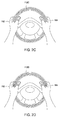
- steering wheel 110 includes sensors 112A positioned within an inner surface of steering wheel 110.
- Sensors 112A are positioned in the manner shown to optimally detect forces exerted by the thumbs and fingers of the driver.
- Sensors 112A may be included within sensors 112 shown in Figure 1A , and therefore may be implemented with any of the sensor types described in conjunction with Figure 1A .
- Sensors 112A are configured to output sensor data to computing device 120 for processing by application 130.
- FIG 2B illustrates another exemplary configuration of force sensors that can be implemented with the steering wheel of Figures 1A-1B , according to various embodiments.
- steering wheel 110 includes sensors 112B positioned within an outer surface of steering wheel 110.
- Sensors 112B are positioned in the manner shown to optimally detect forces exerted by the palms of the driver.
- Sensors 112B may be included within sensors 112 shown in Figure 1A , and therefore may be implemented with any of the sensor types described in conjunction with Figure 1A .
- Sensors 112B are configured to output sensor data to computing device 120 for processing by application 130.
- FIG. 2C illustrates another exemplary configuration of force sensors that can be implemented with the steering wheel of Figures 1A-1B , according to various embodiments.
- steering wheel 110 includes sensors 112C positioned on a front surface of steering wheel 110.
- Sensors 112C are positioned in the manner shown to optimally detect forces exerted by the thumbs and the palms of the driver.
- Sensors 112C may be included within sensors 112 shown in Figure 1A , and therefore may be implemented with any of the sensor types described in conjunction with Figure 1A .
- Sensors 112C are configured to output data readings to computing device 120 for processing by application 130.
- FIG 2D illustrates another exemplary configuration of force sensors that can be implemented with the steering wheel of Figures 1A-1B , according to various embodiments.
- steering wheel 110 includes sensors 112D positioned on a rear surface of steering wheel 110.
- Sensors 112D are positioned in the manner shown to optimally detect forces exerted by the fingers of the driver.
- Sensors 112D may be included within sensors 112 shown in Figure 1A , and therefore may be implemented with any of the sensor types described in conjunction with Figure 1A .
- Sensors 112D are configured to output sensor data to computing device 120 for processing by application 130.
- steering wheel 110 may include some or all of the various types of sensors 112A - 112D shown in those figures. Sensors 112A-112D may measure a wide variety of different types of forces applied to steering wheel 110. Those forces could be static or dynamic forces, torque forces, pressure forces, impulse forces, isometric forces, and so forth, without limitation. Steering wheel 110 may be coupled to a steering column that also includes sensors, as described in greater detail below in conjunction with Figure 3 .
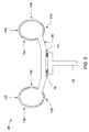
- FIG 3 illustrates a steering assembly that can be implemented with the steering wheel of Figures 1A-1B , according to various embodiments.
- steering assembly 300 includes steering wheel 110 coupled to steering column 310.
- Steering wheel 110 includes sensors 112A-112D described above in conjunction with Figures 2A-2D .
- sensors 312 reside between steering wheel 110 and steering column 310.
- Sensors 312 are configured to measure forces applied by steering wheel 110 onto steering column 310. Sensors 312 are also configured to measure the orientation of steering wheel 110.
- the "orientation" of steering wheel 110 generally refers to any rotation of steering wheel 110 and/or translation of steering wheel 110 relative to steering column 310.
- forces applied by steering wheel 110 onto steering column 310 may originate from the driver of the vehicle providing force inputs to steering wheel 110.
- orientation changes associated with steering wheel 110 may correspond to the driver manipulating steering wheel 110 to navigate the vehicle.
- sensors 312 are also configured to output sensor data to computing device 120 for processing by application 130.
- sensors 312 include a sensor ring coupled to a mounting plate 320 positioned on the back surface of steering wheel 110.
- the sensor ring may measure orientation changes associated with steering wheel 110 as differential readings between sensors disposed on opposite sides of the ring. For example, if one sensor within the sensor ring registered a pressure force, while an opposing sensor within the ring measured a tension force, then the sensor ring could output a torque measurement associated with steering wheel 110 based on the difference between the pressure and tension forces. Alternatively, the sensor ring could output raw sensor readings to application 130, and application 130 could then process those readings to determine the torque measurement.
- application 130 may implement any technically feasible form of signal processing algorithm to determine forces and/or orientation changes applied to steering wheel 110 based on sensor data received from the sensor ring discussed herein.
- application 130 is configured to receive sensor data from sensors 112 and 312 and to then translate those readings, based on interaction mapping 134, into a specific force input performed by the driver. Then, application 130 maps the specific force input, based on command mapping 136, to a command for one of subsystems 140. For example, suppose the driver applies force to the front surface of steering wheel 110. Sensors 112C would measure the applied force and output sensor data to application 130. Application 130 could then translate the applied force, based on interaction mapping 134, to a "two-handed pressure" force input. Then, based on command mapping 136, application 130 would translate the two-handed pressure interaction to a "honk” command. Finally, application 130 could then output the honk command to the vehicle, thereby causing the horn of vehicle 150 to honk.
- driver 160 and steering wheel 110 may identify force inputs provided by driver 160 and steering wheel 110 based on optical data associated with driver 160, as described in greater detail below in conjunction with Figure 4 .
- Figure 4 illustrates an exemplary configuration of an optical sensor for detecting force inputs imparted by the driver of a vehicle, according to various embodiments.
- vehicle 150 includes optical sensor 412.
- the hands of driver 160 are positioned on steering wheel 110.
- Optical sensor 412 is positioned above steering wheel 110 and configured to capture optical data that reflects the positions and configurations of left hand 162 and right hand 164.
- Optical sensor 412 outputs sensor data to application 130 that reflects these positions and configurations, and application 130 then processes that sensor data to identify specific force inputs performed by driver 160 with steering wheel 110. In doing so, application 130 may rely on interaction mapping 134 of Figure 1 to translate video data into specific force inputs.
- Application 130 may implement computer vision techniques, among other possibilities, when identifying those inputs.
- application 130 Upon identifying a force input performed by driver 160, application 130 then maps the specific input, based on command mapping 136, to a command for execution by one of subsystems 140
- application 130 may obtain sensor readings from sensors 112 and 312, as well as sensor readings from optical sensor 412, and then process that data to determine specific interactions that driver 160 performs with steering wheel 110.
- the ability for application 130 to properly map sensor readings to interactions may be improved with optical sensor readings that reflect the hand positions, configurations, and/or motions of the driver.
- the optical data could be processed to disambiguate between force inputs having similar sensor readings provided by sensors 112 and 312.
- application 130 is configured to process sensor readings received from any of the sensors discussed thus far in any technically feasible fashion, including processing one set of sensor readings based on another set of sensor readings.
- Figures 5A-5B illustrate an exemplary scenario where application 130 processes sensor readings received from sensors 112 based on sensor readings received from sensors 312.
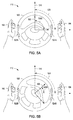
- Figure 5A illustrates different reference frames associated with the steering wheel Figures 1A-1B , according to various embodiments.
- a physical reference frame 500 and a logical reference frame 510 are superimposed over steering wheel 110.
- Physical reference frame 500 is stationary with respect to steering wheel 110, and therefore rotates when steering wheel 110 rotates.
- Logical reference frame 510 is stationary with respect to vehicle 150, and therefore does not rotate when steering wheel 110 rotates.
- Application 130 may compute the respective orientations of physical reference frame 500 and logical reference frame 510 based, at least in part, on sensor readings received from sensors 312.
- Driver 160 may apply forces along perimeter 520 of steering wheel 110 at specific regions 522A and 524A corresponding to left and right hands 162 and 164, respectively, of driver 160.
- Sensors 112 generally measure these applied forces and corresponding magnitudes, as well as the regions where those forces are applied, along perimeter 520.
- the position of region 524A along perimeter 520 forms an angle 526A with physical reference frame 500, and also forms an angle 528 with logical reference frame 510.
- the position of region 522A forms corresponding angles, although these are not shown for simplicity.
- Application 130 is configured to implement several different possible techniques to interpret sensor readings received from sensors 112 as specific force inputs performed by driver 150. In one embodiment, application 130 interprets those sensor readings based on the specific regions along perimeter 520 where the sensor readings are captured relative to physical reference frame 500. In another embodiment, application 130 interprets those sensor readings based on the specific regions along perimeter 520 where the sensor readings are captured relative to logical reference frame 510. These two embodiments are described in greater detail in conjunction with Figure 5B .
- FIG. 5B steering wheel 110 is rotated, and physical reference frame 500 is rotated in corresponding fashion.
- Driver 160 applies forces along perimeter 520 at regions 522B and 524B, which reside slightly counterclockwise along perimeter 520 from regions 522A and 524A, respectively.
- the position of region 524B along perimeter 520 now forms an angle 526B with physical reference frame 500.
- the position of region 524B along perimeter forms angle 528 with logical reference frame 510, similar to the position of region 524A shown in Figure 5A .
- the position of region 524A forms corresponding angles, although these are not shown.
- application 130 may interpret sensors readings from sensors 112 relative to physical reference frame 500.
- application 130 interprets the force inputs shown in Figures 5A and 5B differently, because those inputs correspond to different regions along perimeter 520.
- the inputs shown in Figure 5A involves regions 522A and 524A
- the inputs shown in Figure 5B involve positions 522B and 524B.
- the position of region 524A in Figure 5A forms angle 526A with physical reference frame 500
- the position of region 524B in Figure 5B forms angle 526B with physical reference frame 500.
- application may interpret sensors readings from sensors 112 relative to logical reference frame 510.
- application 130 may rely on sensors 312 to determine the relative angle between physical reference frame 500 and logical reference 510.
- application 130 interprets the force inputs shown in Figures 5A and 5B similarly, because those interactions occur at similar locations along perimeter 520 relative to logical reference 520.
- the inputs shown in Figure 5A occur at regions corresponding to angle 528.
- the inputs shown in Figure 5B also occurs at regions corresponding to angle 528.
- these interactions occur at the same logical positions on steering wheel 110.
- Application 130 may be configured according to either of the two embodiments described above based on a variety of factors. For example, and without limitation, application 130 could be configured to rely on physical reference frame 500 or, alternatively, logical reference frame 510, depending on factory setting, driver configuration, a specific driver profile associated with driver 160, or the operational state of vehicle 150. Application 130 could, for example, and without limitation, transition between the physical reference frame 500 and the logical reference frame 510 based on the speed of the vehicle or other operational states.
- driver 160 need not account for the orientation of steering wheel 110 when performing an interaction. Accordingly, driver 160 may perform interactions in an intuitive manner, without first needing to consider specific regions along perimeter 520 of steering wheel 110 where those interactions should be performed. Driver 160 may provide a wide variety of force inputs to steering wheel 110 to control subsystems 140, as described in greater detail below.
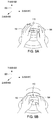
- Figure 6 illustrates the hands of a driver in a resting position on the steering wheel of Figures 1A-1B , according to various embodiments.
- axes 600 include X-axis 610, Y-axis 620, and Z-axis 630.
- Steering wheel 110 rotates around Z-axis 630.
- Left hand 162 of driver 160 resides in the negative X region of axes 600, while right hand 164 of driver 160 resides in the position X region of axes 600.
- the coordinate system described in conjunction with Figure 6 is used in the following Figures 7A-13B to describe the various force inputs that driver 160 may perform with steering wheel 110 and that application 130 may, in turn, detect.
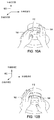
- Figures 7A-7B illustrate how poloidal shear forces can be imparted to the steering wheel of Figures 1A-1B , according to various embodiments.
- driver 160 imparts a poloidal shear force by gripping steering wheel 110 and then rotating left hand 162 and right hand 164 forward in a substantially negative Z direction across the surface of steering wheel 110.
- driver 160 imparts another poloidal force by gripping steering wheel 110 and then rotating left hand 162 and right hand 164 backward in a substantially positive Z direction across the surface of steering wheel 110.
- Figures 8A-8B illustrate how one-handed pressure forces can be imparted to the steering wheel of Figures 1A-1B , according to various embodiments.
- driver 160 imparts a one-handed pressure force by pressing right hand 164 against steering wheel 110 in a negative Z-direction.
- driver 160 imparts another one-handed pressure force by pulling steering wheel 110, using right hand 164, in a positive Z direction.
- Figures 9A-9B illustrate how symmetric two-handed pressure forces can be imparted to the steering wheel of Figures 1A-1B , according to various embodiments.
- driver 160 imparts a two-handed pressure force by pressing left hand 162 and right hand 164 against steering wheel 110 in a negative Z direction.
- driver 160 imparts another two-handed pressure force by pulling steering wheel 110, using left hand 162 and right hand 164, in a positive Z direction.
- Figures 10A-10B illustrate how asymmetric two-handed pressure forces can be imparted to the steering wheel of Figures 1A-1B , according to various embodiments.
- driver 160 imparts a two-handed asymmetric pressure force by pulling steering wheel 110, using left hand 162, in a positive Z-direction, while pressing right hand 164 against steering wheel 110 in a negative Z-direction.
- driver 160 imparts another two-handed asymmetric pressure force by pressing left hand 162 against steering wheel 110 in a negative Z direction while pulling steering wheel 110, using right hand 164, in a positive Z direction.
- Figures 11A-11B illustrate how toroidal shearing forces can be imparted to the steering wheel of Figures 1A-1B , according to various embodiments.
- driver 160 imparts a toroidal shearing force by gripping steering wheel 110 and then exerting a force in a substantially positive Y direction using left hand 162 and right hand 164.
- driver 160 imparts another toroidal shearing force by gripping steering wheel 110 and then exerting a force in a substantially negative Y direction using left hand 162 and right hand 164.
- Figures 12A-12B illustrate how opposing toroidal shearing forces can be imparted to the steering wheel of Figures 1A-1B , according to various embodiments.
- driver 160 imparts a toroidal shearing force by gripping the top of steering wheel 110 with left hand 162 and exerting force in a substantially positive X direction across the surface of steering wheel 110, while also gripping the top of steering wheel 110 with right hand 164 and exerting force in a substantially negative X direction across the surface of steering wheel 110.
- driver 160 imparts another opposing toroidal shearing force by gripping the bottom of steering wheel 110 with left hand 162 and exerting force in a substantially positive X direction across the surface of steering wheel 110, while also gripping the bottom of steering wheel 110 with right hand 164 and exerting force in a substantially negative X direction across the surface of steering wheel 110.
- Figures 13A-13C illustrate how compression and tension forces can be imparted to the steering wheel of Figures 1A-1B , according to various embodiments.
- user 160 imparts a tension force by pulling steering wheel 110, using the fingers of left hand 162, in the negative X direction, while also pulling steering wheel 110, using the fingers of right hand 164, in the positive X direction.
- Figure 13B user 160 imparts another tension force by pulling steering wheel 110, using the thumb of left hand 162, in the negative X direction, while also pulling steering wheel 110, using the thumb of right hand 164, in the positive X direction.
- user 160 imparts a compression force by pressing left hand 162 against steering wheel 110 in the positive X direction, while also pressing right hand 164 against steering wheel 110 in the negative X direction.
- application 130 is configured to receive and process sensor data that may reflect a wide variety of different types of forces that may be imparted into steering wheel 110. Those different forces may correspond to a vast spectrum of different possible force inputs that application 130 may identify. The various identifiable forces may be imparted using a wide variety of different techniques, which may vary based on ergonomic consideration, among other things. As previously discussed, those inputs may then be mapped to particular commands for execution by subsystems 140.
- application 130 is configured to respond to any force imparted into steering wheel 110. Such forces may include those involuntarily imparted by driver 160, as well as those imparted from a source other than driver 160, among other possibilities. For example, and without limitation, if driver 160 causes vehicle 150 to turn, driver 160 could unconsciously grip steering wheel 110 tightly. Application 130 could measure a torque or shear force associated with that gripping, and then identify a specific force input. Application 130 could then map that force input to a command relevant to the current situation associated with driver 160. In this example, that command could, when executed by a braking subsystem associated with vehicle 150, cause vehicle 150 to slow down.
- application 130 may identify the state of being associated with driver 160, based on forces that driver 160 imparts to steering wheel 110, and then take action in response. In doing so, application 130 may compare imparted forces to historical trends identified for driver 160 and/or averaged across other drivers. With this approach, application 130 may adapt to the current cognitive, emotional, and/or mental state of driver 160.
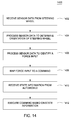
- Figure 14 sets forth a general sequence of processing steps that may be implemented by application 130 to translate force measurements to commands.
- Figure 14 is a flow diagram of method steps for controlling a subsystem within a vehicle, according to various embodiments. Although the method steps are described in conjunction with the systems of Figures 1A-13C , persons skilled in the art will understand that any system configured to perform the method steps, in any order, is within the scope of the various embodiments.
- a method 1400 begins at step 1402, where application 130 within computing device 120 receives sensor data associated with steering wheel 110.
- the sensor data received at step 1402 may include data captured by any of sensors 112A, 112B, 112C, and 112D shown in Figures 2A-2D , respectively, as well as data captured by sensors 312 and/or 412. Accordingly, the sensor data may reflect physical forces imparted by driver 160 into steering wheel 110, the orientation of steering wheel 110, as well as video images showing the hands of driver 160 applying force to steering wheel 110.
- application 130 processes the received sensor data to determine the orientation of steering wheel 110.
- the steering wheel orientation determined at step 1404 may correspond to physical reference frame 500 shown in Figures 5A and 5B .
- the orientation of reference frame 500 is generally derived from sensor data captured by sensors 312 and/or optical sensor 400.
- application 130 processes the sensor data received at step 1402 to identify a force input. In doing so, application 130 may process the received sensor data based on interaction mapping 134. Application 130 may identify the force input relative to physical reference frame 500 or logical reference frame 510, in the manner discussed above in conjunction with Figures 5A-5B . The identified force input may correspond to any of the exemplary inputs described above in conjunction with Figures 7A-13C . The identified force input may also correspond to any technically feasible input to steering wheel 110. In one embodiment, application 130 may emit feedback to driver 160 upon successful identification of a force input. The feedback could be, for example, and without limitation, an audible sound, a visual cue, haptic feedback, and so forth.
- step 1408 application 130 maps the force input identified at step 1406 to a specific command to be executed by one or more of subsystems 140.
- Application 130 may rely on command map 136 when step 1408 is performed.
- command map 136 provides a mapping from force inputs to commands, allowing application 130 determine a particular command based on a specific force input.
- application 130 receives state information from vehicle 150.
- the state information reflects the overall operating state of vehicle 150.
- the operating state of vehicle 150 could include, for example, and without limitation, the speed of vehicle 150, the acceleration of vehicle 150, a power level associated with vehicle 150, a set of configuration parameters associated vehicle 150 and/or driver 160, the physical orientation of steering wheel 110, and one or more operating states associated with subsystems 140, and so forth.
- application 130 causes the command identified at step 1408 to be executed by one of subsystems 140 based on the state information collected at step 1410. In doing so, application 130 may modify the command based on the operating state of the vehicle, thereby accounting for factors such as acceleration, deceleration, turning, and other dynamics associated with vehicle 150. For example, if vehicle 150 is decelerating, then the force input identified at step 1406 may have magnitude that reflects force exerted by driver 160 and a deceleration force associated with vehicle 150. Application 130 may modify the identified command to correct for such additional forces. In one embodiment, application 130 may also adjust the force input identified at step 1406 based on the state information associated with vehicle 150.
- a steering wheel within a vehicle includes a plurality of sensors that measure forces applied to the steering wheel.
- An application executing on a computing device records sensor data from the sensors, and then interprets that data as specific force inputs. The application then translates those force inputs into specific commands that can be executed by subsystems within the vehicle.
- At least one advantage of the techniques set forth herein is that the driver of a vehicle that implements the force control system need not remove either hand from the steering wheel in order to adjust the operation of subsystems within the vehicle, thereby improving driver safety.
- the driver can interact with the force control system without averting visual focus, further improving driver safety. With these techniques, vehicle accidents due to driver distraction may be reduced.
- aspects of the present embodiments may be embodied as a system, method or computer program product. Accordingly, aspects of the present disclosure may take the form of an entirely hardware embodiment, an entirely software embodiment (including firmware, resident software, micro-code, etc.) or an embodiment combining software and hardware aspects that may all generally be referred to herein as a "circuit,” “module” or “system.” Furthermore, aspects of the present disclosure may take the form of a computer program product embodied in one or more computer readable medium(s) having computer readable program code embodied thereon.
- the computer readable medium may be a computer readable signal medium or a computer readable storage medium.
- a computer readable storage medium may be, for example, but not limited to, an electronic, magnetic, optical, electromagnetic, infrared, or semiconductor system, apparatus, or device, or any suitable combination of the foregoing.
- a computer readable storage medium may be any tangible medium that can contain, or store a program for use by or in connection with an instruction execution system, apparatus, or device.
Landscapes
- Engineering & Computer Science (AREA)
- Transportation (AREA)
- Mechanical Engineering (AREA)
- Chemical & Material Sciences (AREA)
- Combustion & Propulsion (AREA)
- Physics & Mathematics (AREA)
- General Physics & Mathematics (AREA)
- Automation & Control Theory (AREA)
- Human Computer Interaction (AREA)
- Steering Controls (AREA)
Abstract
Description
- This application claims the benefit of
United States provisional patent application titled "Force Measuring Steering Wheel," filed on December 31, 2014 and having serial number 62/098,964 - The various embodiments relate generally to human-vehicle interfaces and, more specifically, to a force measuring steering wheel.
- Modern vehicles typically include a variety of subsystems, such as a multimedia subsystem, climate control subsystem, power windows / power locks subsystem, and other similar subsystems. In addition, modern vehicles also generally include several different control panels for controlling those various subsystems. For example, the dashboard of the vehicle could include a multimedia panel and a climate control panel, while the door of the vehicle could include a power windows / power locks panel.
- One problem with the configuration of the different panels described above is that the driver of the vehicle is required to remove at least one hand from the steering wheel in order to manipulate the control panels and control the corresponding subsystems. For example, the driver must remove one of his/her hands from the steering wheel in order to adjust the temperature, fan speed, air conditioner (A/C), and other items on the climate control panel. Another danger posed by this type of arrangement is that the driver is forced to divert focus away from the act of driving in order to interact with the different vehicle subsystems. Such diversions reduce the ability of the driver to control the vehicle, which compromises the safety of both the driver and the other occupants of the vehicle.
- As the foregoing illustrates, techniques for controlling subsystems within a vehicle that do not require drivers to remove their hands from the steering wheel would be useful.
- One or more embodiments set forth include a non-transitory computer-readable medium storing program instructions that, when executed by a processor, cause the processor to control the operation of a plurality of subsystems included within a vehicle, by performing the steps of acquiring data that reflects a force imparted into a steering wheel, processing the data to identify a first force input included in a plurality of force inputs, converting the first force input into a first command, and causing a first subsystem included in the plurality of subsystems to execute the first command.
- At least one advantage of the techniques set forth herein is that the driver of the vehicle need not remove either hand from the steering wheel in order to adjust the operation of subsystems within the vehicle, thereby improving driver safety. In addition, the driver can interact with those subsystems without averting visual focus, further improving driver safety. With these techniques, vehicle accidents due to driver distraction may be reduced.
- So that the manner in which the recited features of the one or more embodiments set forth above can be understood in detail, a more particular description of the one or more embodiments, briefly summarized above, may be had by reference to certain specific embodiments, some of which are illustrated in the appended drawings. It is to be noted, however, that the appended drawings illustrate only typical embodiments and are therefore not to be considered limiting of its scope in any manner, for the scope of the various embodiments subsumes other embodiments as well.
-
Figures 1A-1B illustrate a force control system configured to implement one or more aspects of the various embodiments; -
Figures 2A-2D illustrate different exemplary configurations of sensors that can be implemented with the steering wheel ofFigures 1A-1B , according to various embodiments; -
Figure 3 illustrates a steering assembly that can be implemented with the steering wheel ofFigures 1A-1B , according to various embodiments; -
Figure 4 illustrates an exemplary configuration of an optical sensor for detecting forces imparted by the driver of a vehicle, according to various embodiments; -
Figures 5A-5B illustrate different reference frames associated with the steering wheel ofFigures 1A-1B , according to various embodiments; -
Figure 6 illustrates the hands of a driver in a resting position on the steering wheel ofFigures 1A-1B , according to various embodiments; -
Figures 7A-7B illustrate how poloidal forces can be imparted to the steering wheel ofFigures 1A-1B , according to various embodiments; -
Figures 8A-8B illustrate how one-handed pressure forces can be imparted to the steering wheel ofFigures 1A-1B , according to various embodiments; -
Figures 9A-9B illustrate how symmetric two-handed pressure forces can be imparted to the steering wheel ofFigures 1A-1B , according to various embodiments; -
Figures 10A-10B illustrate how asymmetric two-handed pressure forces can be imparted to the steering wheel ofFigures 1A-1B , according to various embodiments; -
Figures 11A-11B illustrate how toroidal shearing forces can be imparted to the steering wheel ofFigures 1A-1B , according to various embodiments; -
Figures 12A-12B illustrate how opposing toroidal shearing forces can be imparted to the steering wheel ofFigures 1A-1B , according to various embodiments; -
Figures 13A-13C illustrate how compression and tension forces can be imparted to the steering wheel ofFigures 1A-1B , according to various embodiments; and -
Figure 14 is a flow diagram of method steps for controlling a subsystem within a vehicle, according to various embodiments. - In the following description, numerous specific details are set forth to provide a more thorough understanding of certain specific embodiments. However, it will be apparent to one of skill in the art that other embodiments may be practiced without one or more of these specific details or with additional specific details.
-
Figure 1A illustrates a force control system configured to implement one or more aspects of the various embodiments. As shown,control system 100 includes asteering wheel 110 coupled to acomputing device 120 that, in turn, is coupled tosubsystems 140.Subsystems 140 includemultimedia system 142, anavigation device 144,climate control 146, andcruise control 148. The particular subsystems shown are provided for exemplary purposes only, and not meant to limit the scope of the various embodiments.Figure 1B illustrates an exemplary configuration ofcontrol system 100 within an exemplary vehicle. - Referring now to
Figure 1B , as shown,vehicle 150 includessteering wheel 110,computing device 120, andsubsystems 140. As also shown, adriver 160 resides withinvehicle 150.Left hand 162 ofdriver 160 is positioned onsteering wheel 110.Right hand 164 ofdriver 160 is also positioned onsteering wheel 110. - Referring generally to
Figures 1A-1B ,steering wheel 110 may be manipulated, in a conventional fashion, to control the direction ofvehicle 150.Steering wheel 110 may also receive forces imparted by a driver.Control system 100 is configured to measure those forces and then perform a variety of different actions in response, including issuing commands to subsystems 140, as described in greater detail below. -
Steering wheel 110 includes one ormore sensors 112 that are disposed on and/or in thesteering wheel 110 and/or a steering wheel column (not shown). Sensor(s) 112 may implement a wide variety of techniques for detecting forces imparted bydriver 160. The imparted forces could include, for example, and without limitation, pressure forces, torque forces, shearing forces, poloidal and/or toroidal-oriented forces, and so forth.Steering wheel 110 may include any technically feasible kind of sensor capable of measuring any of the aforementioned forces. For example, and without limitation,steering wheel 110 could include pressure sensing, pneumatic sensing, strain gauge load cells, piezoelectric crystals, resistive sensing, capacitive sensing, visual sensing, thermal sensing, ultrasonic sensing, infrared sensing, laser-based sensing, radar-based sensing, time-of-flight sensing and structured light-based sensors, optical sensing of surface elements to determine shearing forces, micro-optical resonators, polymer-based shear force sensors, polymer sheets carpeted with nanohairs, piezoresistive shear sensors, and so forth. - In one embodiment,
steering wheel 110 is configured to deform in response to imparted forces. That deformation may occur at a microscopic structural level withinsteering wheel 110, and therefore may not be noticeable to driver 160. Alternatively, the deformation ofsteering wheel 110 could occur at a macroscopic level that may, in fact, be noticeable to driver 160. In either case,sensors 112 are configured to detect and measure that deformation, and then quantify the imparted forces based on those measurements. - Sensor(s) 112 may be coupled to, or included within,
steering wheel 110 according to a wide variety of different positions and/or orientations. Generally, sensor(s) 112 are located to allowdriver 160 to input forces and/or pressures without removing either hand fromsteering wheel 110, as described in greater detail herein. For example, and without limitation, one ormore sensors 112 may be located proximate to common hand positions assumed bydriver 160 when grasping thesteering wheel 110, and/orsensors 112 may be disposed along the circumference of thesteering wheel 110 to allow the user to interact with the sensor(s) 112 regardless of the orientation (e.g., rotation) of thesteering wheel 110. -
Driver 160 imparts forces and/or pressures (e.g., shear forces and/or grasping pressure) to sensor(s) 112 in order to control the operation ofmultimedia system 142,navigation device 144,climate control 146cruise control 148, and potentially other subsystems (not shown) beyondsubsystems 140. Other subsystems could include, for example, acceleration, braking, a power window subsystem, a power locks subsystem, headlight controls, windshield wiper controls, traction or anti-slip settings, four-wheel drive controls, seat adjustment systems, interior lighting, a powered side and rear view mirror system, and so forth, without limitation. -
Computing device 120 includes aprocessing unit 122, input/output (I/O)devices 124, and amemory unit 126. In various embodiments,computing device 120 may be a mobile computer, a system-on-a-chip (SoC), infotainment system, navigation system, mobile device, mobile phone, personal digital assistant, or any other device suitable for practicing one or more embodiments of the disclosure. As shown,computing device 120 is configured to receive input from sensor(s) 112.Computing device 120 may also be coupled to one or more output devices associated with thecontrol system 100 that include one or more devices, such as haptic devices and/or speakers configured to generate feedback fordriver 160. Generally,computing device 120 is configured to coordinate the overall operation of thecontrol system 100. Any technically feasible system configured to implement the functionality of thecontrol system 100 falls within the scope of the present disclosure. -
Processing unit 122 may be any technically feasible unit configured to process data, including, for example, a central processing unit (CPU) or application-specific integrated circuit (ASIC), without limitation. I/O devices 124 include devices configured to receive input (such as, e.g., a set of buttons, without limitation) devices configured to deliver output (such as, e.g., a display screen, without limitation), as well as devices capable of both receiving input and delivering output (such as, e.g., a universal serial bus (USB) port, without limitation). In some embodiments, I/O devices 124 include one or more devices that implement sensor(s) 112, such as pressure sensors, force sensors, touch sensors, cameras, depth sensors, infrared sensors, time-to-flight sensors, ultrasound sensors, and the like. Accordingly, in some embodiments, I/O devices 124 measure various types of user input, such as forces, pressures, capacitances, button presses, hand positions, input directions, gestures, etc. associated with input received viasteering wheel 110. -
Memory unit 126 may be any technically feasible unit configured to store data and program code, including, for example, a random access memory (RAM) module or a hard disk, without limitation.Memory unit 126 includes one ormore software applications 130 and adatabase 132. Software application(s) 130 withinmemory unit 126 may be executed by processingunit 122 to implement the overall functionality ofcomputing device 120, and, thus, to coordinate the operation of the force measuring steering wheel as a whole.Database 132 includesinteraction mapping 134 andcommand mapping 136.Interaction mapping 134 provides a mapping between force measurements recorded bysensors 112, and specific force inputs, as described in greater detail below.Command mapping 136 provides a mapping between force inputs and specific commands that may be executed bysubsystems 140, as also described in greater detail below. - In operation,
driver 160 exerts physical force onsteering wheel 110 in order to issue commands to subsystems 140.Sensors 112 measure the physical force and output sensor data to computing device that reflects the magnitude, direction, position, and other attributes associated with that force.Application 130 then processes the sensor data, usinginteraction mapping 134, to map the measured force to a specific force input.Interaction mapping 134 could include, for example, and without limitation, an artificial neural network (ANN) configured to process sensor data and output a selection of a force input. The force input could be, for example, and without limitation, a two-handed torque input, a one-handed pressure input, a symmetric shearing force input, and so forth.Figures 7A-13C provide an exemplary set of force inputs that may be included withininteraction mapping 134. - Once
application 130 has mapped the measured force to a particular force input,application 130 may then rely oncommand mapping 136 to map the force input to a specific command.Command mapping 136 could include, for example, and without limitation, a look-up table (LUT) that maps force inputs to commands. The commands could include, for example, and without limitation, a power on command, an increase volume command, an activate windshield wipers command, an accelerate command, a brake command, a traction control command, a navigation command, and so forth. - By implementing the techniques described thus far,
control system 100 allowsdriver 160 to control any functionality associated withvehicle 150, without removing either hand fromsteering wheel 150. Accordingly,driver 160 may operate thevarious subsystems 140 without diverting visual focus from the act of driving, and without sacrificing control ofvehicle 150. The basic approach described above is also described, with reference to exemplary implementations, below in conjunction withFigures 2A-13C . -
Figure 2A illustrates an exemplary configuration of force sensors that can be implemented with the steering wheel ofFigures 1A-1B , according to various embodiments. As shown,steering wheel 110 includessensors 112A positioned within an inner surface ofsteering wheel 110.Sensors 112A are positioned in the manner shown to optimally detect forces exerted by the thumbs and fingers of the driver.Sensors 112A may be included withinsensors 112 shown inFigure 1A , and therefore may be implemented with any of the sensor types described in conjunction withFigure 1A .Sensors 112A are configured to output sensor data tocomputing device 120 for processing byapplication 130. -
Figure 2B illustrates another exemplary configuration of force sensors that can be implemented with the steering wheel ofFigures 1A-1B , according to various embodiments. As shown,steering wheel 110 includessensors 112B positioned within an outer surface ofsteering wheel 110.Sensors 112B are positioned in the manner shown to optimally detect forces exerted by the palms of the driver.Sensors 112B may be included withinsensors 112 shown inFigure 1A , and therefore may be implemented with any of the sensor types described in conjunction withFigure 1A .Sensors 112B are configured to output sensor data tocomputing device 120 for processing byapplication 130. -
Figure 2C illustrates another exemplary configuration of force sensors that can be implemented with the steering wheel ofFigures 1A-1B , according to various embodiments. As shown,steering wheel 110 includessensors 112C positioned on a front surface ofsteering wheel 110.Sensors 112C are positioned in the manner shown to optimally detect forces exerted by the thumbs and the palms of the driver.Sensors 112C may be included withinsensors 112 shown inFigure 1A , and therefore may be implemented with any of the sensor types described in conjunction withFigure 1A .Sensors 112C are configured to output data readings tocomputing device 120 for processing byapplication 130. -
Figure 2D illustrates another exemplary configuration of force sensors that can be implemented with the steering wheel ofFigures 1A-1B , according to various embodiments. As shown,steering wheel 110 includessensors 112D positioned on a rear surface ofsteering wheel 110.Sensors 112D are positioned in the manner shown to optimally detect forces exerted by the fingers of the driver.Sensors 112D may be included withinsensors 112 shown inFigure 1A , and therefore may be implemented with any of the sensor types described in conjunction withFigure 1A .Sensors 112D are configured to output sensor data tocomputing device 120 for processing byapplication 130. - Referring generally to
Figures 2A-2D ,steering wheel 110 may include some or all of the various types ofsensors 112A - 112D shown in those figures.Sensors 112A-112D may measure a wide variety of different types of forces applied tosteering wheel 110. Those forces could be static or dynamic forces, torque forces, pressure forces, impulse forces, isometric forces, and so forth, without limitation.Steering wheel 110 may be coupled to a steering column that also includes sensors, as described in greater detail below in conjunction withFigure 3 . -
Figure 3 illustrates a steering assembly that can be implemented with the steering wheel ofFigures 1A-1B , according to various embodiments. As shown, steeringassembly 300 includessteering wheel 110 coupled tosteering column 310.Steering wheel 110 includessensors 112A-112D described above in conjunction withFigures 2A-2D . As also shown,sensors 312 reside betweensteering wheel 110 andsteering column 310. -
Sensors 312 are configured to measure forces applied bysteering wheel 110 ontosteering column 310.Sensors 312 are also configured to measure the orientation ofsteering wheel 110. The "orientation" ofsteering wheel 110 generally refers to any rotation ofsteering wheel 110 and/or translation ofsteering wheel 110 relative tosteering column 310. In general, forces applied bysteering wheel 110 ontosteering column 310 may originate from the driver of the vehicle providing force inputs tosteering wheel 110. In addition, orientation changes associated withsteering wheel 110 may correspond to the driver manipulatingsteering wheel 110 to navigate the vehicle. Similar tosensors 112A-112D,sensors 312 are also configured to output sensor data tocomputing device 120 for processing byapplication 130. - In one embodiment,
sensors 312 include a sensor ring coupled to a mountingplate 320 positioned on the back surface ofsteering wheel 110. The sensor ring may measure orientation changes associated withsteering wheel 110 as differential readings between sensors disposed on opposite sides of the ring. For example, if one sensor within the sensor ring registered a pressure force, while an opposing sensor within the ring measured a tension force, then the sensor ring could output a torque measurement associated withsteering wheel 110 based on the difference between the pressure and tension forces. Alternatively, the sensor ring could output raw sensor readings toapplication 130, andapplication 130 could then process those readings to determine the torque measurement. Persons skilled in the art will recognize thatapplication 130 may implement any technically feasible form of signal processing algorithm to determine forces and/or orientation changes applied tosteering wheel 110 based on sensor data received from the sensor ring discussed herein. - Referring generally to
Figures 1-3 ,application 130 is configured to receive sensor data fromsensors interaction mapping 134, into a specific force input performed by the driver. Then,application 130 maps the specific force input, based oncommand mapping 136, to a command for one ofsubsystems 140. For example, suppose the driver applies force to the front surface ofsteering wheel 110.Sensors 112C would measure the applied force and output sensor data toapplication 130.Application 130 could then translate the applied force, based oninteraction mapping 134, to a "two-handed pressure" force input. Then, based oncommand mapping 136,application 130 would translate the two-handed pressure interaction to a "honk" command. Finally,application 130 could then output the honk command to the vehicle, thereby causing the horn ofvehicle 150 to honk. - Persons skilled in the art will understand that the configurations of sensors described above in conjunction with
Figures 1-3 are discussed for exemplary purposes only. Any technically feasible approach to identifying force inputs and/or interactions betweendriver 160 andsteering wheel 110 falls within the scope of the various embodiments. For example, and without limitation,application 130 may identify force inputs provided bydriver 160 andsteering wheel 110 based on optical data associated withdriver 160, as described in greater detail below in conjunction withFigure 4 . -
Figure 4 illustrates an exemplary configuration of an optical sensor for detecting force inputs imparted by the driver of a vehicle, according to various embodiments. As shown,vehicle 150 includesoptical sensor 412. The hands ofdriver 160 are positioned onsteering wheel 110.Optical sensor 412 is positioned abovesteering wheel 110 and configured to capture optical data that reflects the positions and configurations ofleft hand 162 andright hand 164.Optical sensor 412 outputs sensor data toapplication 130 that reflects these positions and configurations, andapplication 130 then processes that sensor data to identify specific force inputs performed bydriver 160 withsteering wheel 110. In doing so,application 130 may rely oninteraction mapping 134 ofFigure 1 to translate video data into specific force inputs.Application 130 may implement computer vision techniques, among other possibilities, when identifying those inputs. Upon identifying a force input performed bydriver 160,application 130 then maps the specific input, based oncommand mapping 136, to a command for execution by one ofsubsystems 140 - In some embodiments, the techniques described herein may be implemented in combination with those described above in conjunction with
Figures 1-3 . In particular,application 130 may obtain sensor readings fromsensors optical sensor 412, and then process that data to determine specific interactions thatdriver 160 performs withsteering wheel 110. In some instances, the ability forapplication 130 to properly map sensor readings to interactions may be improved with optical sensor readings that reflect the hand positions, configurations, and/or motions of the driver. Among other things, the optical data could be processed to disambiguate between force inputs having similar sensor readings provided bysensors - As a general matter,
application 130 is configured to process sensor readings received from any of the sensors discussed thus far in any technically feasible fashion, including processing one set of sensor readings based on another set of sensor readings.Figures 5A-5B illustrate an exemplary scenario whereapplication 130 processes sensor readings received fromsensors 112 based on sensor readings received fromsensors 312. -
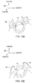
Figure 5A illustrates different reference frames associated with the steering wheelFigures 1A-1B , according to various embodiments. As shown, aphysical reference frame 500 and alogical reference frame 510 are superimposed oversteering wheel 110.Physical reference frame 500 is stationary with respect tosteering wheel 110, and therefore rotates whensteering wheel 110 rotates.Logical reference frame 510 is stationary with respect tovehicle 150, and therefore does not rotate whensteering wheel 110 rotates.Application 130 may compute the respective orientations ofphysical reference frame 500 andlogical reference frame 510 based, at least in part, on sensor readings received fromsensors 312. -
Driver 160 may apply forces alongperimeter 520 ofsteering wheel 110 atspecific regions right hands driver 160.Sensors 112 generally measure these applied forces and corresponding magnitudes, as well as the regions where those forces are applied, alongperimeter 520. The position ofregion 524A alongperimeter 520 forms anangle 526A withphysical reference frame 500, and also forms anangle 528 withlogical reference frame 510. The position ofregion 522A forms corresponding angles, although these are not shown for simplicity. -
Application 130 is configured to implement several different possible techniques to interpret sensor readings received fromsensors 112 as specific force inputs performed bydriver 150. In one embodiment,application 130 interprets those sensor readings based on the specific regions alongperimeter 520 where the sensor readings are captured relative tophysical reference frame 500. In another embodiment,application 130 interprets those sensor readings based on the specific regions alongperimeter 520 where the sensor readings are captured relative tological reference frame 510. These two embodiments are described in greater detail in conjunction withFigure 5B . - In
Figure 5B ,steering wheel 110 is rotated, andphysical reference frame 500 is rotated in corresponding fashion.Driver 160 applies forces alongperimeter 520 atregions perimeter 520 fromregions region 524B alongperimeter 520 now forms anangle 526B withphysical reference frame 500. However, the position ofregion 524B along perimeter formsangle 528 withlogical reference frame 510, similar to the position ofregion 524A shown inFigure 5A . The position ofregion 524A forms corresponding angles, although these are not shown. - According to the first embodiment mentioned above in conjunction with
Figure 5A ,application 130 may interpret sensors readings fromsensors 112 relative tophysical reference frame 500. In this embodiment,application 130 interprets the force inputs shown inFigures 5A and 5B differently, because those inputs correspond to different regions alongperimeter 520. Specifically, the inputs shown inFigure 5A involvesregions Figure 5B involvepositions region 524A inFigure 5A formsangle 526A withphysical reference frame 500, and the position ofregion 524B inFigure 5B formsangle 526B withphysical reference frame 500. - According to the second embodiment mentioned above in conjunction with
Figure 5A , application may interpret sensors readings fromsensors 112 relative tological reference frame 510. In doing so,application 130 may rely onsensors 312 to determine the relative angle betweenphysical reference frame 500 andlogical reference 510. In this embodiment,application 130 interprets the force inputs shown inFigures 5A and 5B similarly, because those interactions occur at similar locations alongperimeter 520 relative tological reference 520. Specifically, the inputs shown inFigure 5A occur at regions corresponding toangle 528. Likewise, the inputs shown inFigure 5B also occurs at regions corresponding toangle 528. Despite those force inputs occurring at different physical regions ofsteering wheel 110, from the perspective of the driver, these interactions occur at the same logical positions onsteering wheel 110. -
Application 130 may be configured according to either of the two embodiments described above based on a variety of factors. For example, and without limitation,application 130 could be configured to rely onphysical reference frame 500 or, alternatively,logical reference frame 510, depending on factory setting, driver configuration, a specific driver profile associated withdriver 160, or the operational state ofvehicle 150.Application 130 could, for example, and without limitation, transition between thephysical reference frame 500 and thelogical reference frame 510 based on the speed of the vehicle or other operational states. - One advantage to implementing the logical reference frame, as discussed in conjunction with the second embodiment, is that
driver 160 need not account for the orientation ofsteering wheel 110 when performing an interaction. Accordingly,driver 160 may perform interactions in an intuitive manner, without first needing to consider specific regions alongperimeter 520 ofsteering wheel 110 where those interactions should be performed.Driver 160 may provide a wide variety of force inputs tosteering wheel 110 to controlsubsystems 140, as described in greater detail below. -
Figure 6 illustrates the hands of a driver in a resting position on the steering wheel ofFigures 1A-1B , according to various embodiments. As shown, axes 600 includeX-axis 610, Y-axis 620, and Z-axis 630.Steering wheel 110 rotates around Z-axis 630.Left hand 162 ofdriver 160 resides in the negative X region ofaxes 600, whileright hand 164 ofdriver 160 resides in the position X region ofaxes 600. The coordinate system described in conjunction withFigure 6 is used in the followingFigures 7A-13B to describe the various force inputs thatdriver 160 may perform withsteering wheel 110 and thatapplication 130 may, in turn, detect. -
Figures 7A-7B illustrate how poloidal shear forces can be imparted to the steering wheel ofFigures 1A-1B , according to various embodiments. As shown inFigure 7A ,driver 160 imparts a poloidal shear force by grippingsteering wheel 110 and then rotatingleft hand 162 andright hand 164 forward in a substantially negative Z direction across the surface ofsteering wheel 110. As shown inFigure 7B ,driver 160 imparts another poloidal force by grippingsteering wheel 110 and then rotatingleft hand 162 andright hand 164 backward in a substantially positive Z direction across the surface ofsteering wheel 110. -
Figures 8A-8B illustrate how one-handed pressure forces can be imparted to the steering wheel ofFigures 1A-1B , according to various embodiments. As shown inFigure 8A ,driver 160 imparts a one-handed pressure force by pressingright hand 164 againststeering wheel 110 in a negative Z-direction. As shown inFigure 8B ,driver 160 imparts another one-handed pressure force by pullingsteering wheel 110, usingright hand 164, in a positive Z direction. -
Figures 9A-9B illustrate how symmetric two-handed pressure forces can be imparted to the steering wheel ofFigures 1A-1B , according to various embodiments. As shown inFigure 9A ,driver 160 imparts a two-handed pressure force by pressingleft hand 162 andright hand 164 againststeering wheel 110 in a negative Z direction. As shown inFigure 9B ,driver 160 imparts another two-handed pressure force by pullingsteering wheel 110, usingleft hand 162 andright hand 164, in a positive Z direction. -
Figures 10A-10B illustrate how asymmetric two-handed pressure forces can be imparted to the steering wheel ofFigures 1A-1B , according to various embodiments. As shown inFigure 10A ,driver 160 imparts a two-handed asymmetric pressure force by pullingsteering wheel 110, usingleft hand 162, in a positive Z-direction, while pressingright hand 164 againststeering wheel 110 in a negative Z-direction. As shown inFigure 10B ,driver 160 imparts another two-handed asymmetric pressure force by pressingleft hand 162 againststeering wheel 110 in a negative Z direction while pullingsteering wheel 110, usingright hand 164, in a positive Z direction. -
Figures 11A-11B illustrate how toroidal shearing forces can be imparted to the steering wheel ofFigures 1A-1B , according to various embodiments. As shown inFigure 11A ,driver 160 imparts a toroidal shearing force by grippingsteering wheel 110 and then exerting a force in a substantially positive Y direction usingleft hand 162 andright hand 164. As shown inFigure 11B ,driver 160 imparts another toroidal shearing force by grippingsteering wheel 110 and then exerting a force in a substantially negative Y direction usingleft hand 162 andright hand 164. -
Figures 12A-12B illustrate how opposing toroidal shearing forces can be imparted to the steering wheel ofFigures 1A-1B , according to various embodiments. As shown inFigure 12A ,driver 160 imparts a toroidal shearing force by gripping the top ofsteering wheel 110 withleft hand 162 and exerting force in a substantially positive X direction across the surface ofsteering wheel 110, while also gripping the top ofsteering wheel 110 withright hand 164 and exerting force in a substantially negative X direction across the surface ofsteering wheel 110. As shown inFigure 12B ,driver 160 imparts another opposing toroidal shearing force by gripping the bottom ofsteering wheel 110 withleft hand 162 and exerting force in a substantially positive X direction across the surface ofsteering wheel 110, while also gripping the bottom ofsteering wheel 110 withright hand 164 and exerting force in a substantially negative X direction across the surface ofsteering wheel 110. -
Figures 13A-13C illustrate how compression and tension forces can be imparted to the steering wheel ofFigures 1A-1B , according to various embodiments. As shown inFigure 13A ,user 160 imparts a tension force by pullingsteering wheel 110, using the fingers ofleft hand 162, in the negative X direction, while also pullingsteering wheel 110, using the fingers ofright hand 164, in the positive X direction. As shown inFigure 13B ,user 160 imparts another tension force by pullingsteering wheel 110, using the thumb ofleft hand 162, in the negative X direction, while also pullingsteering wheel 110, using the thumb ofright hand 164, in the positive X direction. As shown inFigure 13C ,user 160 imparts a compression force by pressingleft hand 162 againststeering wheel 110 in the positive X direction, while also pressingright hand 164 againststeering wheel 110 in the negative X direction. - Persons skilled in the art will understand that the various techniques for imparting forces described above in conjunction with
Figure 7A-13C are provided for exemplary purposes only, and not meant to limit the scope of the various embodiments. Generally,application 130 is configured to receive and process sensor data that may reflect a wide variety of different types of forces that may be imparted intosteering wheel 110. Those different forces may correspond to a vast spectrum of different possible force inputs thatapplication 130 may identify. The various identifiable forces may be imparted using a wide variety of different techniques, which may vary based on ergonomic consideration, among other things. As previously discussed, those inputs may then be mapped to particular commands for execution bysubsystems 140. - In addition, although the forces described above in conjunction with
Figures 7A-13C may appear to be voluntarily initiated bydriver 160,application 130 is configured to respond to any force imparted intosteering wheel 110. Such forces may include those involuntarily imparted bydriver 160, as well as those imparted from a source other thandriver 160, among other possibilities. For example, and without limitation, ifdriver 160 causesvehicle 150 to turn,driver 160 could unconsciously gripsteering wheel 110 tightly.Application 130 could measure a torque or shear force associated with that gripping, and then identify a specific force input.Application 130 could then map that force input to a command relevant to the current situation associated withdriver 160. In this example, that command could, when executed by a braking subsystem associated withvehicle 150,cause vehicle 150 to slow down. In this fashion,application 130 may identify the state of being associated withdriver 160, based on forces thatdriver 160 imparts tosteering wheel 110, and then take action in response. In doing so,application 130 may compare imparted forces to historical trends identified fordriver 160 and/or averaged across other drivers. With this approach,application 130 may adapt to the current cognitive, emotional, and/or mental state ofdriver 160. -
Figure 14 , described below, sets forth a general sequence of processing steps that may be implemented byapplication 130 to translate force measurements to commands. -
Figure 14 is a flow diagram of method steps for controlling a subsystem within a vehicle, according to various embodiments. Although the method steps are described in conjunction with the systems ofFigures 1A-13C , persons skilled in the art will understand that any system configured to perform the method steps, in any order, is within the scope of the various embodiments. - As shown, a
method 1400 begins atstep 1402, whereapplication 130 withincomputing device 120 receives sensor data associated withsteering wheel 110. The sensor data received atstep 1402 may include data captured by any ofsensors Figures 2A-2D , respectively, as well as data captured bysensors 312 and/or 412. Accordingly, the sensor data may reflect physical forces imparted bydriver 160 intosteering wheel 110, the orientation ofsteering wheel 110, as well as video images showing the hands ofdriver 160 applying force tosteering wheel 110. - At
step 1404,application 130 processes the received sensor data to determine the orientation ofsteering wheel 110. The steering wheel orientation determined atstep 1404 may correspond tophysical reference frame 500 shown inFigures 5A and 5B . The orientation ofreference frame 500 is generally derived from sensor data captured bysensors 312 and/or optical sensor 400. - At
step 1406,application 130 processes the sensor data received atstep 1402 to identify a force input. In doing so,application 130 may process the received sensor data based oninteraction mapping 134.Application 130 may identify the force input relative tophysical reference frame 500 orlogical reference frame 510, in the manner discussed above in conjunction withFigures 5A-5B . The identified force input may correspond to any of the exemplary inputs described above in conjunction withFigures 7A-13C . The identified force input may also correspond to any technically feasible input tosteering wheel 110. In one embodiment,application 130 may emit feedback todriver 160 upon successful identification of a force input. The feedback could be, for example, and without limitation, an audible sound, a visual cue, haptic feedback, and so forth. - At
step 1408,application 130 maps the force input identified atstep 1406 to a specific command to be executed by one or more ofsubsystems 140.Application 130 may rely oncommand map 136 whenstep 1408 is performed. As discussed,command map 136 provides a mapping from force inputs to commands, allowingapplication 130 determine a particular command based on a specific force input. - At
step 1410,application 130 receives state information fromvehicle 150. The state information reflects the overall operating state ofvehicle 150. The operating state ofvehicle 150 could include, for example, and without limitation, the speed ofvehicle 150, the acceleration ofvehicle 150, a power level associated withvehicle 150, a set of configuration parameters associatedvehicle 150 and/ordriver 160, the physical orientation ofsteering wheel 110, and one or more operating states associated withsubsystems 140, and so forth. - At
step 1412,application 130 causes the command identified atstep 1408 to be executed by one ofsubsystems 140 based on the state information collected atstep 1410. In doing so,application 130 may modify the command based on the operating state of the vehicle, thereby accounting for factors such as acceleration, deceleration, turning, and other dynamics associated withvehicle 150. For example, ifvehicle 150 is decelerating, then the force input identified atstep 1406 may have magnitude that reflects force exerted bydriver 160 and a deceleration force associated withvehicle 150.Application 130 may modify the identified command to correct for such additional forces. In one embodiment,application 130 may also adjust the force input identified atstep 1406 based on the state information associated withvehicle 150. - In sum, a steering wheel within a vehicle includes a plurality of sensors that measure forces applied to the steering wheel. An application executing on a computing device records sensor data from the sensors, and then interprets that data as specific force inputs. The application then translates those force inputs into specific commands that can be executed by subsystems within the vehicle.
- At least one advantage of the techniques set forth herein is that the driver of a vehicle that implements the force control system need not remove either hand from the steering wheel in order to adjust the operation of subsystems within the vehicle, thereby improving driver safety. In addition, the driver can interact with the force control system without averting visual focus, further improving driver safety. With these techniques, vehicle accidents due to driver distraction may be reduced.
- The descriptions of the various embodiments have been presented for purposes of illustration, but are not intended to be exhaustive or limited to the embodiments disclosed. Many modifications and variations will be apparent to those of ordinary skill in the art without departing from the scope and spirit of the described embodiments.
- Aspects of the present embodiments may be embodied as a system, method or computer program product. Accordingly, aspects of the present disclosure may take the form of an entirely hardware embodiment, an entirely software embodiment (including firmware, resident software, micro-code, etc.) or an embodiment combining software and hardware aspects that may all generally be referred to herein as a "circuit," "module" or "system." Furthermore, aspects of the present disclosure may take the form of a computer program product embodied in one or more computer readable medium(s) having computer readable program code embodied thereon.
- Any combination of one or more computer readable medium(s) may be utilized. The computer readable medium may be a computer readable signal medium or a computer readable storage medium. A computer readable storage medium may be, for example, but not limited to, an electronic, magnetic, optical, electromagnetic, infrared, or semiconductor system, apparatus, or device, or any suitable combination of the foregoing. More specific examples (a non-exhaustive list) of the computer readable storage medium would include the following: an electrical connection having one or more wires, a portable computer diskette, a hard disk, a random access memory (RAM), a read-only memory (ROM), an erasable programmable read-only memory (EPROM or Flash memory), an optical fiber, a portable compact disc read-only memory (CD-ROM), an optical storage device, a magnetic storage device, or any suitable combination of the foregoing. In the context of this document, a computer readable storage medium may be any tangible medium that can contain, or store a program for use by or in connection with an instruction execution system, apparatus, or device.
Claims (15)
- A non-transitory computer-readable medium storing program instructions that, when executed by a processor, cause the processor to control the operation of a plurality of subsystems included within a vehicle, by performing the steps of:acquiring data that reflects a force imparted into a steering wheel;processing the data to identify a first force input included in a plurality of force inputs;converting the first force input into a first command; andcausing a first subsystem included in the plurality of subsystems to execute the first command.
- The non-transitory computer-readable medium of claim 1, further comprising the step of determining an operational state associated with the vehicle and processing the sensor data to identify the force input based on the operational state of the vehicle.
- The non-transitory computer-readable medium of claim 1 or 2, wherein the force comprises at least one of a linear force, an impulse force, a pressure force, a shear force, a torque force, a toroidal force, and a poloidal force.
- A system for controlling the operation of a plurality of subsystems within a vehicle, comprising:a steering wheel;a first plurality of sensors coupled to the steering wheel and configured to acquire first sensor data that reflects a force imparted into the steering wheel; anda computing device coupled to the steering wheel and including:a memory storing a software application, anda processor that, upon executing the software application, is configured to:process the first sensor data to identify a first force input included in a plurality of force inputs;convert the first force input into a first command; andcause a first subsystem included in the plurality of subsystems to execute the first command.
- The system of claim 4, wherein the steering wheel comprises a structure configured to deform in response to the force, and wherein the first sensor data represents the deformation of the steering wheel in response to the force.
- The system of claim 4 or 5, wherein the first plurality of sensors includes:a first set of sensors disposed on an inner perimeter associated with the steering wheel;a second set of sensors disposed on an outer perimeter associated with the steering wheel;a third set of sensors disposed on a front surface of the steering wheel; anda fourth set of sensors disposed on a rear surface of the steering wheel.
- The system of any of claims 4 to 6, wherein the steering wheel further includes a second plurality of sensors mounted between the steering wheel and a steering column, and wherein the second plurality of sensors is configured to acquire second sensor data that reflects an orientation of the steering wheel relative to the steering column.
- The system of claim 7, wherein the processor, upon executing the software application, is further configured to:compute a physical reference frame that is stationary with respect to the steering wheel;compute a logical reference frame that is stationary with respect to the vehicle; andcompute an angle between the physical reference frame and the logical reference frame, wherein the first sensor data is processed, based on the angle, to identify the first force input.
- The system of claim 8, wherein a sensor in the first plurality of sensors or the second plurality of sensors comprises at least one of a pressure sensor, a pneumatic sensor, a strain gauge, a load cell, a piezoelectric crystal, a resistive sensor, a capacitive sensor, a visual sensor, a thermal sensor, an ultrasonic sensor, an infrared sensor, a laser-based sensor, a radar-based sensor, a time-of-flight sensor and a structured light-based sensor.
- The system of any of claims 4 to 9, further comprising an output device, wherein the processor, upon executing the software application and identifying the first force input, is configured to cause the output device to generate first feedback indicating that the first force input was identified.
- The system of claim 10, wherein the first feedback comprises at least one of audio feedback, visual feedback, and haptic feedback directed towards a driver of the vehicle.
- A computer-implemented method for controlling the operation of a plurality of subsystems within a vehicle, the method comprising:acquiring data that reflects a force imparted into a steering wheel;processing the data to identify a first force input included in a plurality of force inputs;converting the first force input into a first command; andcausing a first subsystem included in the plurality of subsystems to execute the first command.
- The computer-implemented method of claim 12, wherein the force comprises a poloidal force that is imparted into the steering wheel when the steering wheel is gripped and twisted.
- The computer-implemented method of claim 12 or 13, wherein the force comprises a pressure force that is imparted into the steering wheel when the steering wheel is pressed or pulled.
- The computer-implemented method of any of claims 12 to 14, wherein the force comprises a toroidal force that is imparted into the steering wheel when the steering wheel is gripped and pressed or gripped and pulled.
Applications Claiming Priority (2)
| Application Number | Priority Date | Filing Date | Title |
|---|---|---|---|
| US201462098964P | 2014-12-31 | 2014-12-31 | |
| US14/806,623 US9994231B2 (en) | 2014-12-31 | 2015-07-22 | Force measuring steering wheel |
Publications (2)
| Publication Number | Publication Date |
|---|---|
| EP3040699A1 true EP3040699A1 (en) | 2016-07-06 |
| EP3040699B1 EP3040699B1 (en) | 2019-09-25 |
Family
ID=54850018
Family Applications (1)
| Application Number | Title | Priority Date | Filing Date |
|---|---|---|---|
| EP15199976.0A Active EP3040699B1 (en) | 2014-12-31 | 2015-12-15 | Force measuring steering wheel |
Country Status (3)
| Country | Link |
|---|---|
| US (1) | US9994231B2 (en) |
| EP (1) | EP3040699B1 (en) |
| CN (1) | CN105730496B (en) |
Cited By (3)
| Publication number | Priority date | Publication date | Assignee | Title |
|---|---|---|---|---|
| DE102016204343A1 (en) * | 2016-03-16 | 2017-09-21 | Bayerische Motoren Werke Aktiengesellschaft | Method and device for deactivating a driver assistance system |
| KR102532730B1 (en) * | 2022-08-02 | 2023-05-16 | (주)삼한엔지니어링 | Measurement system of the real-time lateral forces of automotive tires and monitoring system |
| PL444209A1 (en) * | 2023-03-27 | 2023-11-13 | Politechnika Warszawska | Method for continuous measurement of upper limb fatigue in the car for drivers with disabilities |
Families Citing this family (20)
| Publication number | Priority date | Publication date | Assignee | Title |
|---|---|---|---|---|
| DE102015223688A1 (en) * | 2015-11-30 | 2017-06-01 | Bayerische Motoren Werke Aktiengesellschaft | Arrangement, means of locomotion and method for assuming a driving task by an occupant of a means of transport located in a highly automated driving state |
| GB2545005B (en) * | 2015-12-03 | 2021-09-08 | Bentley Motors Ltd | Responsive human machine interface |
| DE102016224429A1 (en) * | 2015-12-22 | 2017-06-22 | Ford Global Technologies, Llc | Steering wheel for a motor vehicle |
| GB2552984B (en) * | 2016-08-17 | 2018-10-24 | Ford Global Tech Llc | An ultrasonic haptic control system |
| US10889254B2 (en) * | 2016-10-28 | 2021-01-12 | Honda Motor Co., Ltd. | Steering wheel unit |
| US10322727B1 (en) * | 2017-01-18 | 2019-06-18 | State Farm Mutual Automobile Insurance Company | Technology for assessing emotional state of vehicle operator |
| CN108622176B (en) * | 2018-05-23 | 2024-10-29 | 常州星宇车灯股份有限公司 | Multifunctional steering wheel human-vehicle interaction system based on TOF gesture recognition |
| CN108791058A (en) * | 2018-06-27 | 2018-11-13 | 梧州学院 | A kind of safe driving detection device and its control method based on steering wheel grip |
| JP7066582B2 (en) * | 2018-09-12 | 2022-05-13 | 本田技研工業株式会社 | Judgment system, vehicle control system, vehicle, judgment method, and program |
| DE102018129563A1 (en) | 2018-11-23 | 2020-05-28 | Valeo Schalter Und Sensoren Gmbh | Method for determining the steering mode of a steering wheel |
| JP2020138600A (en) * | 2019-02-27 | 2020-09-03 | 本田技研工業株式会社 | Vehicle control system |
| DE102019131683A1 (en) * | 2019-11-22 | 2021-05-27 | Bayerische Motoren Werke Aktiengesellschaft | Means of locomotion, device and method for operating an operating force-sensitive input device of a means of locomotion |
| DE102020111405A1 (en) * | 2020-04-27 | 2021-10-28 | Tdk Electronics Ag | Control element and vehicle with control element |
| KR102934871B1 (en) * | 2020-06-22 | 2026-03-09 | 현대자동차주식회사 | Apparatus for inputting a commend of vehicle, system having the same and method thereof |
| FR3114068B1 (en) * | 2020-09-17 | 2022-07-29 | Renault | Method for controlling a function of a motor vehicle |
| FR3115262B1 (en) * | 2020-10-16 | 2023-01-20 | Commissariat Energie Atomique | Multipoint contact detection device and method |
| US11702138B2 (en) | 2021-05-24 | 2023-07-18 | Toyota Research Institute, Inc. | Method for lateral control assistance to enable one-handed driving of a vehicle |
| CN113815707B (en) * | 2021-09-27 | 2023-04-07 | 同济大学 | Method and system for monitoring holding posture of steering wheel of driver |
| US12594944B2 (en) | 2021-12-16 | 2026-04-07 | Volkswagen Aktiengesellschaft | Method and system for vehicle drive mode selection |
| FR3149575A1 (en) * | 2023-06-12 | 2024-12-13 | Psa Automobiles Sa | Method for selecting a function of a motor vehicle |
Citations (6)
| Publication number | Priority date | Publication date | Assignee | Title |
|---|---|---|---|---|
| DE10318713A1 (en) * | 2002-05-29 | 2003-12-24 | Volkswagen Ag | Car steering wheel electronic control unit has long touch pad to control direction and speed of cursor used to select and display information for car control |
| DE102006023287A1 (en) * | 2006-05-18 | 2007-12-06 | Leopold Kostal Gmbh & Co. Kg | Gripping force sensor for use in steering wheel of motor vehicle, has sensor foils arranged between base body and rim sleeve, where sensor foils has piezoelectric sensor, and base body forms even surface in steering wheel of vehicle |
| US20080061954A1 (en) * | 2006-08-30 | 2008-03-13 | Kulas Charles J | Visual indicators on vehicle steering |
| DE102007024141A1 (en) * | 2007-05-23 | 2008-11-27 | Takata-Petri Ag | Sensor system for steering wheel and component, particularly seat or steering wheel rim of motor vehicle, has sensor unit arranged in or at component for detection of impact of compressive force or torsion force on component |
| WO2013176944A2 (en) * | 2012-05-25 | 2013-11-28 | George Stantchev | Steering wheel with remote control capabilities |
| US20140151356A1 (en) * | 2012-11-30 | 2014-06-05 | Tk Holdings Inc. | Hand sensing on steering wheel using heater element |
Family Cites Families (18)
| Publication number | Priority date | Publication date | Assignee | Title |
|---|---|---|---|---|
| US20020104705A1 (en) | 2001-02-02 | 2002-08-08 | Kuhn Robert M. | Steering wheel assembly with integrated brake and throttle controls |
| DE10160717A1 (en) * | 2001-12-11 | 2003-06-18 | Mercedes Benz Lenkungen Gmbh | Steering for motor vehicle with planetary gearbox and drive for superimposing torque on steering wheel has drive for applying torque directly to steering column |
| DE20120542U1 (en) * | 2001-12-19 | 2002-05-02 | TRW Automotive Safety Systems GmbH & Co. KG, 63743 Aschaffenburg | Steering device for a motor vehicle |
| US6868934B2 (en) | 2003-07-09 | 2005-03-22 | Honda Giken Kogyo Kabushiki Kaisha | Variable power steering assist using driver grip pressure |
| DE102004016029A1 (en) * | 2004-03-30 | 2005-10-20 | Ralf Trachte | Flexible computer input |
| US7295904B2 (en) * | 2004-08-31 | 2007-11-13 | International Business Machines Corporation | Touch gesture based interface for motor vehicle |
| JP4814594B2 (en) * | 2005-09-14 | 2011-11-16 | 日立オートモティブシステムズ株式会社 | In-vehicle equipment operation device |
| JP5228439B2 (en) * | 2007-10-22 | 2013-07-03 | 三菱電機株式会社 | Operation input device |
| DE102008021973A1 (en) * | 2008-05-02 | 2009-11-05 | Bayerische Motoren Werke Aktiengesellschaft | Vehicle steering system of the by-wire design |
| JP5948711B2 (en) | 2009-12-18 | 2016-07-06 | 本田技研工業株式会社 | Deformable pad for tactile control |
| US8738224B2 (en) * | 2011-01-12 | 2014-05-27 | GM Global Technology Operations LLC | Steering wheel system |
| US20120232751A1 (en) * | 2011-03-07 | 2012-09-13 | Jorge Guspan | Pressure-Sensitive Steering Wheel Controls |
| GB201118621D0 (en) * | 2011-10-27 | 2011-12-07 | Jaguar Cars | Improvements in electric power assisted steering (EPAS) systems |
| JP2014240234A (en) * | 2013-06-11 | 2014-12-25 | 株式会社日本自動車部品総合研究所 | Steering control device |
| FR3010378B1 (en) * | 2013-09-10 | 2017-01-13 | Jtekt Europe Sas | METHOD FOR REAL-TIME CALCULATION OF THE ABSOLUTE POSITION OF AN ASSISTED STEERING ASSEMBLY WITH IMPROVED PRECISION |
| FR3018917B1 (en) * | 2014-03-18 | 2016-04-01 | Jtekt Europe Sas | MODELING FRICTION IN A DIRECTION ASSISTED BY A CLOUD OF POINTS |
| US20150307022A1 (en) * | 2014-04-23 | 2015-10-29 | Ford Global Technologies, Llc | Haptic steering wheel |
| KR101621747B1 (en) * | 2014-12-15 | 2016-05-17 | 주식회사 만도 | Electric Steering Apparatus and Controlling Method of the Same |
-
2015
- 2015-07-22 US US14/806,623 patent/US9994231B2/en active Active
- 2015-12-15 EP EP15199976.0A patent/EP3040699B1/en active Active
- 2015-12-29 CN CN201511017463.XA patent/CN105730496B/en active Active
Patent Citations (6)
| Publication number | Priority date | Publication date | Assignee | Title |
|---|---|---|---|---|
| DE10318713A1 (en) * | 2002-05-29 | 2003-12-24 | Volkswagen Ag | Car steering wheel electronic control unit has long touch pad to control direction and speed of cursor used to select and display information for car control |
| DE102006023287A1 (en) * | 2006-05-18 | 2007-12-06 | Leopold Kostal Gmbh & Co. Kg | Gripping force sensor for use in steering wheel of motor vehicle, has sensor foils arranged between base body and rim sleeve, where sensor foils has piezoelectric sensor, and base body forms even surface in steering wheel of vehicle |
| US20080061954A1 (en) * | 2006-08-30 | 2008-03-13 | Kulas Charles J | Visual indicators on vehicle steering |
| DE102007024141A1 (en) * | 2007-05-23 | 2008-11-27 | Takata-Petri Ag | Sensor system for steering wheel and component, particularly seat or steering wheel rim of motor vehicle, has sensor unit arranged in or at component for detection of impact of compressive force or torsion force on component |
| WO2013176944A2 (en) * | 2012-05-25 | 2013-11-28 | George Stantchev | Steering wheel with remote control capabilities |
| US20140151356A1 (en) * | 2012-11-30 | 2014-06-05 | Tk Holdings Inc. | Hand sensing on steering wheel using heater element |
Cited By (5)
| Publication number | Priority date | Publication date | Assignee | Title |
|---|---|---|---|---|
| DE102016204343A1 (en) * | 2016-03-16 | 2017-09-21 | Bayerische Motoren Werke Aktiengesellschaft | Method and device for deactivating a driver assistance system |
| US10710604B2 (en) | 2016-03-16 | 2020-07-14 | Bayerische Motoren Werke Aktiengesellschaft | Method and device for deactivating a driver assistance system |
| KR102532730B1 (en) * | 2022-08-02 | 2023-05-16 | (주)삼한엔지니어링 | Measurement system of the real-time lateral forces of automotive tires and monitoring system |
| PL444209A1 (en) * | 2023-03-27 | 2023-11-13 | Politechnika Warszawska | Method for continuous measurement of upper limb fatigue in the car for drivers with disabilities |
| PL249537B1 (en) * | 2023-03-27 | 2026-05-04 | Politechnika Warszawska | Method for continuous measurement of upper limb fatigue in the car for drivers with disabilities |
Also Published As
| Publication number | Publication date |
|---|---|
| US20160185356A1 (en) | 2016-06-30 |
| EP3040699B1 (en) | 2019-09-25 |
| CN105730496B (en) | 2019-10-15 |
| US9994231B2 (en) | 2018-06-12 |
| CN105730496A (en) | 2016-07-06 |
Similar Documents
| Publication | Publication Date | Title |
|---|---|---|
| US9994231B2 (en) | Force measuring steering wheel | |
| US10725655B2 (en) | Operation apparatus | |
| US10053110B2 (en) | Systems and methodologies for controlling an autonomous vehicle | |
| US10035539B2 (en) | Steering wheel control system | |
| JP2018150043A (en) | System for information transmission in motor vehicle | |
| KR20200103901A (en) | Gesture interface system for autonomous vehicle and operating method thereof | |
| US10029568B2 (en) | System for warning of drowsiness of driver and method thereof | |
| US10095313B2 (en) | Input device, vehicle having the input device, and method for controlling the vehicle | |
| JP6613170B2 (en) | Vehicle control unit and control method thereof | |
| US10065504B2 (en) | Intelligent tutorial for gestures | |
| KR20150079435A (en) | Systems and methods for controlling multiple displays with single controller and haptic enabled user interface | |
| CN104881117B (en) | A kind of apparatus and method that speech control module is activated by gesture identification | |
| CN107416009A (en) | Driver detects steering wheel | |
| US20140168068A1 (en) | System and method for manipulating user interface using wrist angle in vehicle | |
| JP2014225245A (en) | Traffic information presentation system, traffic information presentation method and electronic device | |
| CN108016296A (en) | Vehicle display based on car speed | |
| JP6233248B2 (en) | Gripping state determination device, gripping state determination method, input device, input acquisition method | |
| JP5136948B2 (en) | Vehicle control device | |
| EP3572917B1 (en) | Coordinate input apparatus | |
| CN114919650B (en) | Steering assist control method, apparatus, device, and computer-readable storage medium | |
| EP4220356A1 (en) | Vehicle, apparatus, method and computer program for obtaining user input information | |
| CN106873881B (en) | Electronic equipment and toy control method | |
| TWI895915B (en) | Auxiliary operation system and auxiliary operation method for vehicle device | |
| JP2016139373A (en) | Operating device | |
| JP2025178122A (en) | Providing a user interface for controlling a touchscreen in a vehicle using multi-finger gestures |
Legal Events
| Date | Code | Title | Description |
|---|---|---|---|
| PUAI | Public reference made under article 153(3) epc to a published international application that has entered the european phase |
Free format text: ORIGINAL CODE: 0009012 |
|
| AK | Designated contracting states |
Kind code of ref document: A1 Designated state(s): AL AT BE BG CH CY CZ DE DK EE ES FI FR GB GR HR HU IE IS IT LI LT LU LV MC MK MT NL NO PL PT RO RS SE SI SK SM TR |
|
| AX | Request for extension of the european patent |
Extension state: BA ME |
|
| STAA | Information on the status of an ep patent application or granted ep patent |
Free format text: STATUS: REQUEST FOR EXAMINATION WAS MADE |
|
| 17P | Request for examination filed |
Effective date: 20170104 |
|
| RBV | Designated contracting states (corrected) |
Designated state(s): AL AT BE BG CH CY CZ DE DK EE ES FI FR GB GR HR HU IE IS IT LI LT LU LV MC MK MT NL NO PL PT RO RS SE SI SK SM TR |
|
| STAA | Information on the status of an ep patent application or granted ep patent |
Free format text: STATUS: EXAMINATION IS IN PROGRESS |
|
| 17Q | First examination report despatched |
Effective date: 20170620 |
|
| REG | Reference to a national code |
Ref country code: DE Ref legal event code: R079 Ref document number: 602015038595 Country of ref document: DE Free format text: PREVIOUS MAIN CLASS: G01L0005220000 Ipc: B60W0050000000 |
|
| GRAP | Despatch of communication of intention to grant a patent |
Free format text: ORIGINAL CODE: EPIDOSNIGR1 |
|
| STAA | Information on the status of an ep patent application or granted ep patent |
Free format text: STATUS: GRANT OF PATENT IS INTENDED |
|
| RIC1 | Information provided on ipc code assigned before grant |
Ipc: B62D 1/04 20060101ALI20190325BHEP Ipc: B62D 1/06 20060101ALI20190325BHEP Ipc: B60K 37/06 20060101ALI20190325BHEP Ipc: B60W 50/00 20060101AFI20190325BHEP Ipc: B60K 35/00 20060101ALI20190325BHEP Ipc: G01L 5/22 20060101ALI20190325BHEP |
|
| INTG | Intention to grant announced |
Effective date: 20190415 |
|
| GRAS | Grant fee paid |
Free format text: ORIGINAL CODE: EPIDOSNIGR3 |
|
| GRAA | (expected) grant |
Free format text: ORIGINAL CODE: 0009210 |
|
| STAA | Information on the status of an ep patent application or granted ep patent |
Free format text: STATUS: THE PATENT HAS BEEN GRANTED |
|
| AK | Designated contracting states |
Kind code of ref document: B1 Designated state(s): AL AT BE BG CH CY CZ DE DK EE ES FI FR GB GR HR HU IE IS IT LI LT LU LV MC MK MT NL NO PL PT RO RS SE SI SK SM TR |
|
| REG | Reference to a national code |
Ref country code: GB Ref legal event code: FG4D |
|
| REG | Reference to a national code |
Ref country code: CH Ref legal event code: EP |
|
| REG | Reference to a national code |
Ref country code: AT Ref legal event code: REF Ref document number: 1183537 Country of ref document: AT Kind code of ref document: T Effective date: 20191015 |
|
| REG | Reference to a national code |
Ref country code: IE Ref legal event code: FG4D |
|
| REG | Reference to a national code |
Ref country code: DE Ref legal event code: R096 Ref document number: 602015038595 Country of ref document: DE |
|
| REG | Reference to a national code |
Ref country code: NL Ref legal event code: MP Effective date: 20190925 |
|
| PG25 | Lapsed in a contracting state [announced via postgrant information from national office to epo] |
Ref country code: NO Free format text: LAPSE BECAUSE OF FAILURE TO SUBMIT A TRANSLATION OF THE DESCRIPTION OR TO PAY THE FEE WITHIN THE PRESCRIBED TIME-LIMIT Effective date: 20191225 Ref country code: SE Free format text: LAPSE BECAUSE OF FAILURE TO SUBMIT A TRANSLATION OF THE DESCRIPTION OR TO PAY THE FEE WITHIN THE PRESCRIBED TIME-LIMIT Effective date: 20190925 Ref country code: HR Free format text: LAPSE BECAUSE OF FAILURE TO SUBMIT A TRANSLATION OF THE DESCRIPTION OR TO PAY THE FEE WITHIN THE PRESCRIBED TIME-LIMIT Effective date: 20190925 Ref country code: FI Free format text: LAPSE BECAUSE OF FAILURE TO SUBMIT A TRANSLATION OF THE DESCRIPTION OR TO PAY THE FEE WITHIN THE PRESCRIBED TIME-LIMIT Effective date: 20190925 Ref country code: LT Free format text: LAPSE BECAUSE OF FAILURE TO SUBMIT A TRANSLATION OF THE DESCRIPTION OR TO PAY THE FEE WITHIN THE PRESCRIBED TIME-LIMIT Effective date: 20190925 Ref country code: BG Free format text: LAPSE BECAUSE OF FAILURE TO SUBMIT A TRANSLATION OF THE DESCRIPTION OR TO PAY THE FEE WITHIN THE PRESCRIBED TIME-LIMIT Effective date: 20191225 |
|
| REG | Reference to a national code |
Ref country code: LT Ref legal event code: MG4D |
|
| PG25 | Lapsed in a contracting state [announced via postgrant information from national office to epo] |
Ref country code: GR Free format text: LAPSE BECAUSE OF FAILURE TO SUBMIT A TRANSLATION OF THE DESCRIPTION OR TO PAY THE FEE WITHIN THE PRESCRIBED TIME-LIMIT Effective date: 20191226 Ref country code: RS Free format text: LAPSE BECAUSE OF FAILURE TO SUBMIT A TRANSLATION OF THE DESCRIPTION OR TO PAY THE FEE WITHIN THE PRESCRIBED TIME-LIMIT Effective date: 20190925 Ref country code: LV Free format text: LAPSE BECAUSE OF FAILURE TO SUBMIT A TRANSLATION OF THE DESCRIPTION OR TO PAY THE FEE WITHIN THE PRESCRIBED TIME-LIMIT Effective date: 20190925 |
|
| REG | Reference to a national code |
Ref country code: AT Ref legal event code: MK05 Ref document number: 1183537 Country of ref document: AT Kind code of ref document: T Effective date: 20190925 |
|
| PG25 | Lapsed in a contracting state [announced via postgrant information from national office to epo] |
Ref country code: PT Free format text: LAPSE BECAUSE OF FAILURE TO SUBMIT A TRANSLATION OF THE DESCRIPTION OR TO PAY THE FEE WITHIN THE PRESCRIBED TIME-LIMIT Effective date: 20200127 Ref country code: ES Free format text: LAPSE BECAUSE OF FAILURE TO SUBMIT A TRANSLATION OF THE DESCRIPTION OR TO PAY THE FEE WITHIN THE PRESCRIBED TIME-LIMIT Effective date: 20190925 Ref country code: AL Free format text: LAPSE BECAUSE OF FAILURE TO SUBMIT A TRANSLATION OF THE DESCRIPTION OR TO PAY THE FEE WITHIN THE PRESCRIBED TIME-LIMIT Effective date: 20190925 Ref country code: NL Free format text: LAPSE BECAUSE OF FAILURE TO SUBMIT A TRANSLATION OF THE DESCRIPTION OR TO PAY THE FEE WITHIN THE PRESCRIBED TIME-LIMIT Effective date: 20190925 Ref country code: PL Free format text: LAPSE BECAUSE OF FAILURE TO SUBMIT A TRANSLATION OF THE DESCRIPTION OR TO PAY THE FEE WITHIN THE PRESCRIBED TIME-LIMIT Effective date: 20190925 Ref country code: RO Free format text: LAPSE BECAUSE OF FAILURE TO SUBMIT A TRANSLATION OF THE DESCRIPTION OR TO PAY THE FEE WITHIN THE PRESCRIBED TIME-LIMIT Effective date: 20190925 Ref country code: AT Free format text: LAPSE BECAUSE OF FAILURE TO SUBMIT A TRANSLATION OF THE DESCRIPTION OR TO PAY THE FEE WITHIN THE PRESCRIBED TIME-LIMIT Effective date: 20190925 Ref country code: EE Free format text: LAPSE BECAUSE OF FAILURE TO SUBMIT A TRANSLATION OF THE DESCRIPTION OR TO PAY THE FEE WITHIN THE PRESCRIBED TIME-LIMIT Effective date: 20190925 Ref country code: IT Free format text: LAPSE BECAUSE OF FAILURE TO SUBMIT A TRANSLATION OF THE DESCRIPTION OR TO PAY THE FEE WITHIN THE PRESCRIBED TIME-LIMIT Effective date: 20190925 |
|
| PG25 | Lapsed in a contracting state [announced via postgrant information from national office to epo] |
Ref country code: SM Free format text: LAPSE BECAUSE OF FAILURE TO SUBMIT A TRANSLATION OF THE DESCRIPTION OR TO PAY THE FEE WITHIN THE PRESCRIBED TIME-LIMIT Effective date: 20190925 Ref country code: SK Free format text: LAPSE BECAUSE OF FAILURE TO SUBMIT A TRANSLATION OF THE DESCRIPTION OR TO PAY THE FEE WITHIN THE PRESCRIBED TIME-LIMIT Effective date: 20190925 Ref country code: CZ Free format text: LAPSE BECAUSE OF FAILURE TO SUBMIT A TRANSLATION OF THE DESCRIPTION OR TO PAY THE FEE WITHIN THE PRESCRIBED TIME-LIMIT Effective date: 20190925 Ref country code: IS Free format text: LAPSE BECAUSE OF FAILURE TO SUBMIT A TRANSLATION OF THE DESCRIPTION OR TO PAY THE FEE WITHIN THE PRESCRIBED TIME-LIMIT Effective date: 20200224 |
|
| REG | Reference to a national code |
Ref country code: DE Ref legal event code: R097 Ref document number: 602015038595 Country of ref document: DE |
|
| PG2D | Information on lapse in contracting state deleted |
Ref country code: IS |
|
| PG25 | Lapsed in a contracting state [announced via postgrant information from national office to epo] |
Ref country code: DK Free format text: LAPSE BECAUSE OF FAILURE TO SUBMIT A TRANSLATION OF THE DESCRIPTION OR TO PAY THE FEE WITHIN THE PRESCRIBED TIME-LIMIT Effective date: 20190925 Ref country code: IS Free format text: LAPSE BECAUSE OF FAILURE TO SUBMIT A TRANSLATION OF THE DESCRIPTION OR TO PAY THE FEE WITHIN THE PRESCRIBED TIME-LIMIT Effective date: 20200126 |
|
| PLBE | No opposition filed within time limit |
Free format text: ORIGINAL CODE: 0009261 |
|
| REG | Reference to a national code |
Ref country code: CH Ref legal event code: PL |
|
| STAA | Information on the status of an ep patent application or granted ep patent |
Free format text: STATUS: NO OPPOSITION FILED WITHIN TIME LIMIT |
|
| REG | Reference to a national code |
Ref country code: BE Ref legal event code: MM Effective date: 20191231 |
|
| PG25 | Lapsed in a contracting state [announced via postgrant information from national office to epo] |
Ref country code: MC Free format text: LAPSE BECAUSE OF FAILURE TO SUBMIT A TRANSLATION OF THE DESCRIPTION OR TO PAY THE FEE WITHIN THE PRESCRIBED TIME-LIMIT Effective date: 20190925 |
|
| 26N | No opposition filed |
Effective date: 20200626 |
|
| GBPC | Gb: european patent ceased through non-payment of renewal fee |
Effective date: 20191225 |
|
| PG25 | Lapsed in a contracting state [announced via postgrant information from national office to epo] |
Ref country code: FR Free format text: LAPSE BECAUSE OF NON-PAYMENT OF DUE FEES Effective date: 20191231 Ref country code: LU Free format text: LAPSE BECAUSE OF NON-PAYMENT OF DUE FEES Effective date: 20191215 Ref country code: GB Free format text: LAPSE BECAUSE OF NON-PAYMENT OF DUE FEES Effective date: 20191225 Ref country code: IE Free format text: LAPSE BECAUSE OF NON-PAYMENT OF DUE FEES Effective date: 20191215 |
|
| PG25 | Lapsed in a contracting state [announced via postgrant information from national office to epo] |
Ref country code: CH Free format text: LAPSE BECAUSE OF NON-PAYMENT OF DUE FEES Effective date: 20191231 Ref country code: SI Free format text: LAPSE BECAUSE OF FAILURE TO SUBMIT A TRANSLATION OF THE DESCRIPTION OR TO PAY THE FEE WITHIN THE PRESCRIBED TIME-LIMIT Effective date: 20190925 Ref country code: BE Free format text: LAPSE BECAUSE OF NON-PAYMENT OF DUE FEES Effective date: 20191231 Ref country code: LI Free format text: LAPSE BECAUSE OF NON-PAYMENT OF DUE FEES Effective date: 20191231 |
|
| PG25 | Lapsed in a contracting state [announced via postgrant information from national office to epo] |
Ref country code: CY Free format text: LAPSE BECAUSE OF FAILURE TO SUBMIT A TRANSLATION OF THE DESCRIPTION OR TO PAY THE FEE WITHIN THE PRESCRIBED TIME-LIMIT Effective date: 20190925 |
|
| PG25 | Lapsed in a contracting state [announced via postgrant information from national office to epo] |
Ref country code: HU Free format text: LAPSE BECAUSE OF FAILURE TO SUBMIT A TRANSLATION OF THE DESCRIPTION OR TO PAY THE FEE WITHIN THE PRESCRIBED TIME-LIMIT; INVALID AB INITIO Effective date: 20151215 Ref country code: MT Free format text: LAPSE BECAUSE OF FAILURE TO SUBMIT A TRANSLATION OF THE DESCRIPTION OR TO PAY THE FEE WITHIN THE PRESCRIBED TIME-LIMIT Effective date: 20190925 |
|
| PG25 | Lapsed in a contracting state [announced via postgrant information from national office to epo] |
Ref country code: TR Free format text: LAPSE BECAUSE OF FAILURE TO SUBMIT A TRANSLATION OF THE DESCRIPTION OR TO PAY THE FEE WITHIN THE PRESCRIBED TIME-LIMIT Effective date: 20190925 |
|
| PG25 | Lapsed in a contracting state [announced via postgrant information from national office to epo] |
Ref country code: MK Free format text: LAPSE BECAUSE OF FAILURE TO SUBMIT A TRANSLATION OF THE DESCRIPTION OR TO PAY THE FEE WITHIN THE PRESCRIBED TIME-LIMIT Effective date: 20190925 |
|
| P01 | Opt-out of the competence of the unified patent court (upc) registered |
Effective date: 20230527 |
|
| PGFP | Annual fee paid to national office [announced via postgrant information from national office to epo] |
Ref country code: DE Payment date: 20251126 Year of fee payment: 11 |