EP3040571A1 - Clutch and/or brake module - Google Patents
Clutch and/or brake module Download PDFInfo
- Publication number
- EP3040571A1 EP3040571A1 EP14153363.8A EP14153363A EP3040571A1 EP 3040571 A1 EP3040571 A1 EP 3040571A1 EP 14153363 A EP14153363 A EP 14153363A EP 3040571 A1 EP3040571 A1 EP 3040571A1
- Authority
- EP
- European Patent Office
- Prior art keywords
- clutch
- brake module
- heat sink
- friction disc
- actuation system
- Prior art date
- Legal status (The legal status is an assumption and is not a legal conclusion. Google has not performed a legal analysis and makes no representation as to the accuracy of the status listed.)
- Granted
Links
Images


Classifications
-
- F—MECHANICAL ENGINEERING; LIGHTING; HEATING; WEAPONS; BLASTING
- F16—ENGINEERING ELEMENTS AND UNITS; GENERAL MEASURES FOR PRODUCING AND MAINTAINING EFFECTIVE FUNCTIONING OF MACHINES OR INSTALLATIONS; THERMAL INSULATION IN GENERAL
- F16D—COUPLINGS FOR TRANSMITTING ROTATION; CLUTCHES; BRAKES
- F16D13/00—Friction clutches
- F16D13/58—Details
- F16D13/72—Features relating to cooling
-
- F—MECHANICAL ENGINEERING; LIGHTING; HEATING; WEAPONS; BLASTING
- F16—ENGINEERING ELEMENTS AND UNITS; GENERAL MEASURES FOR PRODUCING AND MAINTAINING EFFECTIVE FUNCTIONING OF MACHINES OR INSTALLATIONS; THERMAL INSULATION IN GENERAL
- F16D—COUPLINGS FOR TRANSMITTING ROTATION; CLUTCHES; BRAKES
- F16D13/00—Friction clutches
- F16D13/58—Details
- F16D13/70—Pressure members, e.g. pressure plates, for clutch-plates or lamellae; Guiding arrangements for pressure members
-
- F—MECHANICAL ENGINEERING; LIGHTING; HEATING; WEAPONS; BLASTING
- F16—ENGINEERING ELEMENTS AND UNITS; GENERAL MEASURES FOR PRODUCING AND MAINTAINING EFFECTIVE FUNCTIONING OF MACHINES OR INSTALLATIONS; THERMAL INSULATION IN GENERAL
- F16D—COUPLINGS FOR TRANSMITTING ROTATION; CLUTCHES; BRAKES
- F16D25/00—Fluid-actuated clutches
- F16D25/12—Details not specific to one of the before-mentioned types
- F16D25/123—Details not specific to one of the before-mentioned types in view of cooling and lubrication
-
- F—MECHANICAL ENGINEERING; LIGHTING; HEATING; WEAPONS; BLASTING
- F16—ENGINEERING ELEMENTS AND UNITS; GENERAL MEASURES FOR PRODUCING AND MAINTAINING EFFECTIVE FUNCTIONING OF MACHINES OR INSTALLATIONS; THERMAL INSULATION IN GENERAL
- F16D—COUPLINGS FOR TRANSMITTING ROTATION; CLUTCHES; BRAKES
- F16D55/00—Brakes with substantially-radial braking surfaces pressed together in axial direction, e.g. disc brakes
- F16D55/24—Brakes with substantially-radial braking surfaces pressed together in axial direction, e.g. disc brakes with a plurality of axially-movable discs, lamellae, or pads, pressed from one side towards an axially-located member
- F16D55/26—Brakes with substantially-radial braking surfaces pressed together in axial direction, e.g. disc brakes with a plurality of axially-movable discs, lamellae, or pads, pressed from one side towards an axially-located member without self-tightening action
- F16D55/28—Brakes with only one rotating disc
- F16D55/32—Brakes with only one rotating disc actuated by a fluid-pressure device arranged in or on the brake
-
- F—MECHANICAL ENGINEERING; LIGHTING; HEATING; WEAPONS; BLASTING
- F16—ENGINEERING ELEMENTS AND UNITS; GENERAL MEASURES FOR PRODUCING AND MAINTAINING EFFECTIVE FUNCTIONING OF MACHINES OR INSTALLATIONS; THERMAL INSULATION IN GENERAL
- F16D—COUPLINGS FOR TRANSMITTING ROTATION; CLUTCHES; BRAKES
- F16D55/00—Brakes with substantially-radial braking surfaces pressed together in axial direction, e.g. disc brakes
- F16D55/24—Brakes with substantially-radial braking surfaces pressed together in axial direction, e.g. disc brakes with a plurality of axially-movable discs, lamellae, or pads, pressed from one side towards an axially-located member
- F16D55/26—Brakes with substantially-radial braking surfaces pressed together in axial direction, e.g. disc brakes with a plurality of axially-movable discs, lamellae, or pads, pressed from one side towards an axially-located member without self-tightening action
- F16D55/36—Brakes with a plurality of rotating discs all lying side by side
-
- F—MECHANICAL ENGINEERING; LIGHTING; HEATING; WEAPONS; BLASTING
- F16—ENGINEERING ELEMENTS AND UNITS; GENERAL MEASURES FOR PRODUCING AND MAINTAINING EFFECTIVE FUNCTIONING OF MACHINES OR INSTALLATIONS; THERMAL INSULATION IN GENERAL
- F16D—COUPLINGS FOR TRANSMITTING ROTATION; CLUTCHES; BRAKES
- F16D65/00—Parts or details
- F16D65/14—Actuating mechanisms for brakes; Means for initiating operation at a predetermined position
- F16D65/16—Actuating mechanisms for brakes; Means for initiating operation at a predetermined position arranged in or on the brake
- F16D65/18—Actuating mechanisms for brakes; Means for initiating operation at a predetermined position arranged in or on the brake adapted for drawing members together, e.g. for disc brakes
- F16D65/186—Actuating mechanisms for brakes; Means for initiating operation at a predetermined position arranged in or on the brake adapted for drawing members together, e.g. for disc brakes with full-face force-applying member, e.g. annular
-
- F—MECHANICAL ENGINEERING; LIGHTING; HEATING; WEAPONS; BLASTING
- F16—ENGINEERING ELEMENTS AND UNITS; GENERAL MEASURES FOR PRODUCING AND MAINTAINING EFFECTIVE FUNCTIONING OF MACHINES OR INSTALLATIONS; THERMAL INSULATION IN GENERAL
- F16D—COUPLINGS FOR TRANSMITTING ROTATION; CLUTCHES; BRAKES
- F16D65/00—Parts or details
- F16D65/78—Features relating to cooling
- F16D65/84—Features relating to cooling for disc brakes
-
- F—MECHANICAL ENGINEERING; LIGHTING; HEATING; WEAPONS; BLASTING
- F16—ENGINEERING ELEMENTS AND UNITS; GENERAL MEASURES FOR PRODUCING AND MAINTAINING EFFECTIVE FUNCTIONING OF MACHINES OR INSTALLATIONS; THERMAL INSULATION IN GENERAL
- F16D—COUPLINGS FOR TRANSMITTING ROTATION; CLUTCHES; BRAKES
- F16D55/00—Brakes with substantially-radial braking surfaces pressed together in axial direction, e.g. disc brakes
- F16D2055/0004—Parts or details of disc brakes
- F16D2055/0058—Fully lined, i.e. braking surface extending over the entire disc circumference
-
- F—MECHANICAL ENGINEERING; LIGHTING; HEATING; WEAPONS; BLASTING
- F16—ENGINEERING ELEMENTS AND UNITS; GENERAL MEASURES FOR PRODUCING AND MAINTAINING EFFECTIVE FUNCTIONING OF MACHINES OR INSTALLATIONS; THERMAL INSULATION IN GENERAL
- F16D—COUPLINGS FOR TRANSMITTING ROTATION; CLUTCHES; BRAKES
- F16D65/00—Parts or details
- F16D65/02—Braking members; Mounting thereof
- F16D2065/13—Parts or details of discs or drums
- F16D2065/1304—Structure
- F16D2065/1324—Structure carrying friction elements
-
- F—MECHANICAL ENGINEERING; LIGHTING; HEATING; WEAPONS; BLASTING
- F16—ENGINEERING ELEMENTS AND UNITS; GENERAL MEASURES FOR PRODUCING AND MAINTAINING EFFECTIVE FUNCTIONING OF MACHINES OR INSTALLATIONS; THERMAL INSULATION IN GENERAL
- F16D—COUPLINGS FOR TRANSMITTING ROTATION; CLUTCHES; BRAKES
- F16D2300/00—Special features for couplings or clutches
- F16D2300/02—Overheat protection, i.e. means for protection against overheating
- F16D2300/021—Cooling features not provided for in group F16D13/72 or F16D25/123, e.g. heat transfer details
Definitions
- the invention relates to a clutch and/or brake module comprising:
- Such a clutch and/or brake module is generally known.
- the friction disc (on both sides provided with a lining) is located between two heat sinks and the pressure force is applied on one of the heat sinks.
- the discharge of heat of the axially movable heat sink is often the limiting factor of the performance of the brake or clutch.
- the clutch and/or brake module according to the invention is characterized in that no further heat sink, which during operation (braking/coupling) has a rotation speed difference with the friction disc, is present between the friction disc and the actuation system. Because no axially movable heat sink is present, all of the friction heat is discharged through the in the axial direction non-movable heat sink.
- the solid heat sink can be cooled well, because it is secured to the crankshaft or a housing part.
- the external cooling of an axially movable heat sink is always difficult.
- the axially movable heat sink in a dry plate brake or clutch is always the limiting factor for the heat capacity of the clutch or brake. With the clutch and/or brake module of the invention, the capacity can be increased with a factor of 3 due to the absence of the axially movable heat sink.
- the module may be a clutch module in which the plate is a clutch plate, the cooling body is a further rotational member (for example, a transmission axis), and the disc is a clutch disc.
- the module can also be a brake module in which the plate is a brake plate, the cooling body is the fixed world (for example, transmission housing), and the disc is a brake disc.
- the module can also be a combined clutch and brake module equipped with a clutch disc and a brake disc, as well as a clutch plate and a brake plate, and a rotational member and a fixed world.
- the clutch and/or brake module further comprises a pressure plate, which is located axially between the friction disc and the actuation system, wherein the actuation system can exercise an axial pressure force on the pressure plate.
- the friction plate and the pressure plate are preferably fixed to one another in the direction of rotation, for example by means of a spline connection.
- an embodiment of the clutch and/or brake module according to the invention is characterized in that the actuation system comprises actuation means (for example, a cylinder-piston combination, whether or not equipped with a lever), as well as an axial bearing (bearing with rolling elements, such as a ball bearing, needle roller bearing, thrust bearing, or a sliding bearing) which is present between the pressure plate and the actuation means.
- the actuation system can exert the axial force on the pressure plate from the fixed world.
- the axial bearing is preferably oil-lubricated or grease-lubricated and the dry friction material is preferably present in a dry environment, so that it does not need to be lubricated.
- a further embodiment of the clutch and/or brake module according to the invention is characterized in that the clutch and/or brake module further comprises a further friction disc, which is also provided with a lining on at least one side and with this side is faced towards the heat sink, wherein the actuation system can exercise a further pressing force on the further friction disc, wherein the further friction disc is axially located between the heat sink and the actuation system and between the further friction disc and the actuation system there is no further heat sink, which during operation has a rotation speed difference with the friction disc.
- the clutch and/or brake module preferably comprises a further pressure plate which is located axially between the further friction disc and the actuation means, wherein the actuation system can exercise an axial pressure force on the further pressure plate.
- the rotational member consists of or is connected to a first rotation body of an epicyclic gearing (e.g., a planetary gear train), wherein a second rotation body of the epicyclic gearing can be connected to a drive source and a third rotation body can be connected to wheels of a vehicle or an input shaft of a transmission, wherein the epicyclic gearing is non-lubricated or is lubricated by grease.
- an epicyclic gearing e.g., a planetary gear train
- FIG. 1 a basic embodiment of the clutch and/or brake module according to the invention is shown, which module is designed as a brake module.
- the brake module 1 has a heat sink 3 which is attached to a cooling body for the purpose of discharging heat.
- the cooling body is a transmission housing.
- the brake module further has a brake disc 5 (friction disc), which is connected to a rotational member formed by a shaft 7 (schematically indicated by a center line).
- the brake disc is provided on one side with a lining 9, and faces with this side towards the heat sink 3.
- the brake is a dry brake and is not lubricated.
- the brake module further has an actuation system 11 (cylinder with piston movable therein, schematically indicated by an arrow) which can exert an axial pressing force directly on the brake disc 5.
- the brake disc is located axially between the heat sink and the actuation system.
- the heat sink 3 is secured to a transmission housing 13, a part of which is schematically shown.
- Figures 2 and 3 show two embodiments of the brake module 1' and 1" in which the actuation force of a plunger of the actuation system 11 is transmitted to the brake disc 5 through an axial bearing 15 and through a pressure plate 17.
- the thrust bearing is oil lubricated or grease lubricated.
- the plunger can be positioned on different radii by the use of an intermediate plate 19.
- the actuation system is such that from the fixed world the axial force can be exerted on the pressure plate.
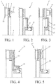
- Figures 4 and 5 show two further embodiments in which the force of the actuation system is transmitted on the friction disc through an axial bearing.
- a lever 23 is provided which can increase the pressure force to the brake disc.
- the reaction force is supported on a further thrust bearing 25 and in the embodiment shown in figure 5 , the reaction force is supported on a second brake disc 27, which is tangentially coupled to the first disc, but is axially movable with respect to this brake disc.
- Figure 6 shows an embodiment of the brake module 31, in which the axial force on the two friction discs 35 and 37 is transmitted by means of a lever 33.
- the heat sink 39 is located between the two brake discs.
- the pressure plate can be activated by a compression spring, which increases the actuation force on the pressure plate.
- Figure 7 shows an embodiment of the brake module 41, in which the axial force is transferred on the pressure plate 45 through a rolling bearing 43.
- the axis of rotation of the rolling bearing is (substantially) at right angles to the axis of rotation of the brake disc 47.
- FIG 8 shows an embodiment of a clutch module 51 in accordance with the invention.
- the clutch disc 53 is connected to a pressure plate 55 and the cooling plate 57 constitutes the heat sink of the clutch.
- the axial force is applied to the pressure plate through a first axial bearing 59 and a lever 61.
- the reaction force is supported on the heat sink via a further axial bearing 63.
- the heat sink is attached to or is a part of an engine flywheel 65 of an internal combustion engine and is (or can be) attached to a crankshaft.
- the clutch is closed when not energized.
- Figures 9 and 10 show embodiments of the clutch module 71, 71', wherein the heat sink 73 is located halfway between two friction discs 75 and 77.
- the friction discs are tangentially connected with each other, and can move axially relative to each other. In the embodiment shown in Figure 9 , in the non-actuated state the clutch is closed and in the embodiment shown in Figure 10 in non-actuated state the clutch is open.
- FIG 11 shows an embodiment of the clutch module 81 in which a ring gear 83 is connected to the heat sink 85. Between the ring gear and the heat sink a one way bearing/clutch may be present (for start-stop application).
- a brake module 91 which is equipped with a clutch 93 and which is connected to a flywheel via a planetary gear set 95.
- the pressure plate is connected via an intermediate plate to a first rotation body of the planetary set, wherein a second rotation body of the planetary set is connected to a drive source and a third rotation body is connected to one of the wheels of a vehicle or to an input shaft of a transmission comprising at least two different ratios and being connected to one or more of the wheels of a vehicle.
- a clutch may be present between two rotation bodies of the epicyclic gearing.
- the planetary set is non-lubricated or grease lubricated.
- Figure 13 shows an alternative brake module 101, which is not part of the invention represented by the two heat sinks 103 and 105 one of which is formed by an axially movable plunger.
- This plunger is cooled by a cooling liquid which also during the movement of the plunger continues to flow through a cooling channel 107 present in the plunger.
Abstract
Description
- The invention relates to a clutch and/or brake module comprising:
- a heat sink, which is attached to a cooling body (for example, a flywheel, or a transmission housing) for the purpose of discharging heat;
- a friction disc which is connected to a rotational member (for example, a transmission input shaft or a rotation body of a planetary gear train) which can rotate about the same axis as the friction disc, which friction disc on at least one side is provided with a lining and is faced with this side towards the heat sink; and
- an actuation system with which an axial pressing force on the friction disc can be exercised, in which the friction disc is located axially between the heat sink and the actuation system.
- Such a clutch and/or brake module is generally known. In the known clutch and/or brake module the friction disc (on both sides provided with a lining) is located between two heat sinks and the pressure force is applied on one of the heat sinks. The discharge of heat of the axially movable heat sink is often the limiting factor of the performance of the brake or clutch.
- It is an object of the invention to provide a clutch and/or brake module of the type described in the opening paragraph in which the heat is better discharged than in the known module, and thus the brake or clutch can meet higher requirements in respect of braking power or torque transfer. To this end, the clutch and/or brake module according to the invention is characterized in that no further heat sink, which during operation (braking/coupling) has a rotation speed difference with the friction disc, is present between the friction disc and the actuation system. Because no axially movable heat sink is present, all of the friction heat is discharged through the in the axial direction non-movable heat sink. Because the pressing force is exerted on the friction disc and not on an axially movable heat sink, it is sufficient to have only one heat sink, and non-complicated facilities can be used to discharge heat in a sufficient way. This construction is especially advantageous in case the clutch and/or brake module is equipped with a dry friction disc because in such a module the discharge of heat is more of an issue than in a wet environment.
- The solid heat sink can be cooled well, because it is secured to the crankshaft or a housing part. The external cooling of an axially movable heat sink is always difficult. The axially movable heat sink in a dry plate brake or clutch is always the limiting factor for the heat capacity of the clutch or brake. With the clutch and/or brake module of the invention, the capacity can be increased with a factor of 3 due to the absence of the axially movable heat sink.
- The module may be a clutch module in which the plate is a clutch plate, the cooling body is a further rotational member (for example, a transmission axis), and the disc is a clutch disc. The module can also be a brake module in which the plate is a brake plate, the cooling body is the fixed world (for example, transmission housing), and the disc is a brake disc. The module can also be a combined clutch and brake module equipped with a clutch disc and a brake disc, as well as a clutch plate and a brake plate, and a rotational member and a fixed world.
- Preferably, the clutch and/or brake module further comprises a pressure plate, which is located axially between the friction disc and the actuation system, wherein the actuation system can exercise an axial pressure force on the pressure plate.
- In this case the friction plate and the pressure plate are preferably fixed to one another in the direction of rotation, for example by means of a spline connection.
- An embodiment of the clutch and/or brake module according to the invention is characterized in that the actuation system comprises actuation means (for example, a cylinder-piston combination, whether or not equipped with a lever), as well as an axial bearing (bearing with rolling elements, such as a ball bearing, needle roller bearing, thrust bearing, or a sliding bearing) which is present between the pressure plate and the actuation means. The actuation system can exert the axial force on the pressure plate from the fixed world. The axial bearing is preferably oil-lubricated or grease-lubricated and the dry friction material is preferably present in a dry environment, so that it does not need to be lubricated.
- A further embodiment of the clutch and/or brake module according to the invention is characterized in that the clutch and/or brake module further comprises a further friction disc, which is also provided with a lining on at least one side and with this side is faced towards the heat sink, wherein the actuation system can exercise a further pressing force on the further friction disc, wherein the further friction disc is axially located between the heat sink and the actuation system and between the further friction disc and the actuation system there is no further heat sink, which during operation has a rotation speed difference with the friction disc.
- In the above embodiment, the clutch and/or brake module preferably comprises a further pressure plate which is located axially between the further friction disc and the actuation means, wherein the actuation system can exercise an axial pressure force on the further pressure plate.
- Yet a further embodiment of the clutch and/or brake module according to the invention is characterized in that the rotational member consists of or is connected to a first rotation body of an epicyclic gearing (e.g., a planetary gear train), wherein a second rotation body of the epicyclic gearing can be connected to a drive source and a third rotation body can be connected to wheels of a vehicle or an input shaft of a transmission, wherein the epicyclic gearing is non-lubricated or is lubricated by grease.
- The invention will be further elucidated below on the basis of drawings. These drawings show embodiments of the clutch and/or brake module according to the present invention. In the drawings:
-
Figure 1 is a basic embodiment of a brake module according to the invention; -
Figures 2 and 3 show two embodiments, in which the actuation force of an actuator is transmitted to the friction disc through an axial bearing; -
Figures 4 and 5 show two further embodiments, in which the actuation force of the actuator is transmitted to the friction disc through an axial bearing; -
Figure 6 shows an embodiment, in which the axial force is transmitted to two friction wheels through a lever; -
Figure 7 shows an embodiment, in which by means of a roller bearing, the axial force is transmitted to the pressure plate; -
Figure 8 shows an embodiment of a clutch module according to the invention; -
Figures 9 and10 show embodiments of a clutch module, wherein the heat sink is located between two friction discs; -
Figure 11 shows an embodiment in which a ring gear is connected to the heat sink; -
Figure 12 shows an embodiment of a brake module according to the invention equipped with a clutch; and -
Figure 13 is an alternative brake module, which is not part of the invention, with two cooling plates of which one is axially movable. - In
Figure 1 a basic embodiment of the clutch and/or brake module according to the invention is shown, which module is designed as a brake module. Thebrake module 1 has aheat sink 3 which is attached to a cooling body for the purpose of discharging heat. In this embodiment the cooling body is a transmission housing. The brake module further has a brake disc 5 (friction disc), which is connected to a rotational member formed by a shaft 7 (schematically indicated by a center line). The brake disc is provided on one side with alining 9, and faces with this side towards theheat sink 3. The brake is a dry brake and is not lubricated. - The brake module further has an actuation system 11 (cylinder with piston movable therein, schematically indicated by an arrow) which can exert an axial pressing force directly on the
brake disc 5. The brake disc is located axially between the heat sink and the actuation system. Theheat sink 3 is secured to atransmission housing 13, a part of which is schematically shown. -
Figures 2 and 3 show two embodiments of thebrake module 1' and 1" in which the actuation force of a plunger of theactuation system 11 is transmitted to thebrake disc 5 through an axial bearing 15 and through apressure plate 17. The thrust bearing is oil lubricated or grease lubricated. The plunger can be positioned on different radii by the use of anintermediate plate 19. The actuation system is such that from the fixed world the axial force can be exerted on the pressure plate. -
Figures 4 and 5 show two further embodiments in which the force of the actuation system is transmitted on the friction disc through an axial bearing. In thebrake modules 21 and 21', alever 23 is provided which can increase the pressure force to the brake disc. In the embodiment shown inFigure 4 the reaction force is supported on a further thrust bearing 25 and in the embodiment shown infigure 5 , the reaction force is supported on asecond brake disc 27, which is tangentially coupled to the first disc, but is axially movable with respect to this brake disc. -
Figure 6 shows an embodiment of thebrake module 31, in which the axial force on the twofriction discs heat sink 39 is located between the two brake discs. The pressure plate can be activated by a compression spring, which increases the actuation force on the pressure plate. -
Figure 7 shows an embodiment of thebrake module 41, in which the axial force is transferred on thepressure plate 45 through a rollingbearing 43. The axis of rotation of the rolling bearing is (substantially) at right angles to the axis of rotation of thebrake disc 47. -
Figure 8 shows an embodiment of aclutch module 51 in accordance with the invention. Theclutch disc 53 is connected to apressure plate 55 and the coolingplate 57 constitutes the heat sink of the clutch. The axial force is applied to the pressure plate through a firstaxial bearing 59 and alever 61. The reaction force is supported on the heat sink via a furtheraxial bearing 63. The heat sink is attached to or is a part of anengine flywheel 65 of an internal combustion engine and is (or can be) attached to a crankshaft. The clutch is closed when not energized. -
Figures 9 and10 show embodiments of theclutch module 71, 71', wherein theheat sink 73 is located halfway between twofriction discs Figure 9 , in the non-actuated state the clutch is closed and in the embodiment shown inFigure 10 in non-actuated state the clutch is open. -
Figure 11 shows an embodiment of theclutch module 81 in which aring gear 83 is connected to theheat sink 85. Between the ring gear and the heat sink a one way bearing/clutch may be present (for start-stop application). - In
figure 12 an embodiment of abrake module 91 is shown which is equipped with a clutch 93 and which is connected to a flywheel via a planetary gear set 95. The pressure plate is connected via an intermediate plate to a first rotation body of the planetary set, wherein a second rotation body of the planetary set is connected to a drive source and a third rotation body is connected to one of the wheels of a vehicle or to an input shaft of a transmission comprising at least two different ratios and being connected to one or more of the wheels of a vehicle. A clutch may be present between two rotation bodies of the epicyclic gearing. The planetary set is non-lubricated or grease lubricated. -
Figure 13 shows analternative brake module 101, which is not part of the invention represented by the twoheat sinks cooling channel 107 present in the plunger. - Although the present invention is elucidated above on the basis of the given drawings, it should be noted that this invention is not limited whatsoever to the embodiments shown in the drawings. The invention also extends to all embodiments deviating from the embodiments shown in the drawings within the context defined by the claims.
Claims (7)
- Clutch and/or brake module comprising:- a heat sink, which is attached to a cooling body for the purpose of discharging heat;- a friction disc which is connected to a rotational member which can rotate about the same axis as the friction disc, which friction disc on at least one side is provided with a lining and is faced with this side towards the heat sink; and- an actuation system with which an axial pressing force on the friction disk can be exercised, in which the friction disk is located axially between the heat sink and the actuation system,characterized in that no further heat sink, which during operation has a rotation speed difference with the friction disc, is present between the friction disc and the actuation system.
- Clutch and/or brake module according to claim 1, characterized in that the clutch and/or brake module further comprises a pressure plate, which is located axially between the friction disc and the actuation system, wherein the actuation system can exercise an axial pressure force on the pressure plate.
- Clutch and/or brake module according to claim 2, characterized in that the friction plate and the pressure plate are fixed to one another in the direction of rotation.
- Clutch and/or brake module according to claim 3, characterized in that the actuation system comprises actuation means, as well as an axial bearing which is present between the pressure plate and the actuation means.
- Clutch and/or brake module according to any one of the preceding claims, characterized in that the clutch and/or brake module further comprises a further friction disc, which is also provided with a lining on at least one side and with this side is faced towards the heat sink, wherein the actuation system can exercise a further pressing force on the further friction disc, wherein the further friction disc is axially located between the heat sink and the actuation system and between the further friction disc and the actuation system there is no further heat sink, which during operation has a rotation speed difference with the friction disc.
- Clutch and/or brake module according to claim 5, characterized in that the clutch and/or brake module comprises a further pressure plate which is located axially between the further friction disc and the actuation means, wherein the actuation system can exercise an axial pressure force on the further pressure plate.
- Clutch and/or brake module according to any one of the preceding claims, characterized in that the rotational member consists of or is connected to a first rotation body of an epicyclic gearing, wherein a second rotation body of the epicyclic gearing can be connected to a drive source and a third rotation body can be connected to wheels of a vehicle or an input shaft of a transmission, wherein the epicyclic gearing is non-lubricated or is lubricated by grease.
Priority Applications (1)
| Application Number | Priority Date | Filing Date | Title |
|---|---|---|---|
| EP14153363.8A EP3040571B1 (en) | 2014-01-31 | 2014-01-31 | Brake Module |
Applications Claiming Priority (1)
| Application Number | Priority Date | Filing Date | Title |
|---|---|---|---|
| EP14153363.8A EP3040571B1 (en) | 2014-01-31 | 2014-01-31 | Brake Module |
Publications (2)
| Publication Number | Publication Date |
|---|---|
| EP3040571A1 true EP3040571A1 (en) | 2016-07-06 |
| EP3040571B1 EP3040571B1 (en) | 2020-05-06 |
Family
ID=56080938
Family Applications (1)
| Application Number | Title | Priority Date | Filing Date |
|---|---|---|---|
| EP14153363.8A Active EP3040571B1 (en) | 2014-01-31 | 2014-01-31 | Brake Module |
Country Status (1)
| Country | Link |
|---|---|
| EP (1) | EP3040571B1 (en) |
Citations (7)
| Publication number | Priority date | Publication date | Assignee | Title |
|---|---|---|---|---|
| FR1055608A (en) * | 1952-05-09 | 1954-02-19 | Clutch refinements | |
| US2699850A (en) * | 1950-09-19 | 1955-01-18 | Rakos Nicholas | Clutch and brake control for reverse gear mechanism |
| US2893524A (en) * | 1958-11-18 | 1959-07-07 | Ferrier Peter | Clutches |
| CH363861A (en) * | 1958-10-22 | 1962-08-15 | Gruenbaum Heinrich | Device for exerting axial pressure on friction disks |
| DE1233671B (en) * | 1959-02-25 | 1967-02-02 | Twin Disc Clutch Co | Disc friction clutch |
| JP2008126883A (en) * | 2006-11-22 | 2008-06-05 | Toyota Motor Corp | Connecting device, power output device equipped with the same, and hybrid automobile |
| EP2529969A1 (en) * | 2011-06-03 | 2012-12-05 | Mecaprom Technologies Corporation Italia SRL A Socio Unico | Motor generator |
Family Cites Families (1)
| Publication number | Priority date | Publication date | Assignee | Title |
|---|---|---|---|---|
| DE112010004994T5 (en) * | 2009-12-25 | 2013-01-10 | Exedy Corporation | coupling device |
-
2014
- 2014-01-31 EP EP14153363.8A patent/EP3040571B1/en active Active
Patent Citations (7)
| Publication number | Priority date | Publication date | Assignee | Title |
|---|---|---|---|---|
| US2699850A (en) * | 1950-09-19 | 1955-01-18 | Rakos Nicholas | Clutch and brake control for reverse gear mechanism |
| FR1055608A (en) * | 1952-05-09 | 1954-02-19 | Clutch refinements | |
| CH363861A (en) * | 1958-10-22 | 1962-08-15 | Gruenbaum Heinrich | Device for exerting axial pressure on friction disks |
| US2893524A (en) * | 1958-11-18 | 1959-07-07 | Ferrier Peter | Clutches |
| DE1233671B (en) * | 1959-02-25 | 1967-02-02 | Twin Disc Clutch Co | Disc friction clutch |
| JP2008126883A (en) * | 2006-11-22 | 2008-06-05 | Toyota Motor Corp | Connecting device, power output device equipped with the same, and hybrid automobile |
| EP2529969A1 (en) * | 2011-06-03 | 2012-12-05 | Mecaprom Technologies Corporation Italia SRL A Socio Unico | Motor generator |
Also Published As
| Publication number | Publication date |
|---|---|
| EP3040571B1 (en) | 2020-05-06 |
Similar Documents
| Publication | Publication Date | Title |
|---|---|---|
| US20180244145A1 (en) | Internal Combustion Engine Decoupling Device of a PHEV Transmission Unit | |
| US8517888B1 (en) | Mechanical power transmission system and method | |
| KR102561026B1 (en) | Clutch device for hybrid drive system | |
| EP1445506A1 (en) | Multi-disk friction device with selective lubrification on demand | |
| CN108138859B (en) | Friction clutch with rotary axis | |
| JP2005180702A5 (en) | ||
| US9890818B2 (en) | Clutch and/or brake module | |
| EP1830095A1 (en) | Double clutch transmission for a motor vehicle | |
| CN105387097B (en) | For transmitting the device of torque | |
| CN107035782B (en) | Clutch with gear rack and planetary mechanism | |
| CN104019208B (en) | Speed change device with hydraulic control mechanism | |
| US7325662B2 (en) | Dry friction launch clutch for an automatic transmission and method | |
| CN109154333B (en) | Clutch device and hybrid module | |
| CN102313000B (en) | Braking three-plate planetary speed reducer with small teeth difference | |
| CN103899728B (en) | A kind of Pneumatic-control type dual planetary gear brake coupling | |
| EP3040571B1 (en) | Brake Module | |
| KR101786804B1 (en) | Dual clutch | |
| RU2647341C1 (en) | Clutch assembly of transmission line of vehicle | |
| US8298107B1 (en) | Retrofit kit for an Allison transmission | |
| CN111417549B (en) | Start and deceleration module | |
| KR101473574B1 (en) | Device for driving multiple-disc clutch for vehicle | |
| KR101448394B1 (en) | Clutch actuator for automated manual transmisson | |
| KR101941731B1 (en) | Multiple free disc-type clutch | |
| CN104895969B (en) | Clutch and/or breaker module | |
| CN111433086B (en) | Drive train with start-up and speed-reduction module |
Legal Events
| Date | Code | Title | Description |
|---|---|---|---|
| PUAI | Public reference made under article 153(3) epc to a published international application that has entered the european phase |
Free format text: ORIGINAL CODE: 0009012 |
|
| AK | Designated contracting states |
Kind code of ref document: A1 Designated state(s): AL AT BE BG CH CY CZ DE DK EE ES FI FR GB GR HR HU IE IS IT LI LT LU LV MC MK MT NL NO PL PT RO RS SE SI SK SM TR |
|
| AX | Request for extension of the european patent |
Extension state: BA ME |
|
| STAA | Information on the status of an ep patent application or granted ep patent |
Free format text: STATUS: REQUEST FOR EXAMINATION WAS MADE |
|
| 17P | Request for examination filed |
Effective date: 20170106 |
|
| RBV | Designated contracting states (corrected) |
Designated state(s): AL AT BE BG CH CY CZ DE DK EE ES FI FR GB GR HR HU IE IS IT LI LT LU LV MC MK MT NL NO PL PT RO RS SE SI SK SM TR |
|
| STAA | Information on the status of an ep patent application or granted ep patent |
Free format text: STATUS: EXAMINATION IS IN PROGRESS |
|
| 17Q | First examination report despatched |
Effective date: 20170719 |
|
| RIC1 | Information provided on ipc code assigned before grant |
Ipc: F16D 55/00 20060101ALN20190321BHEP Ipc: F16D 55/32 20060101ALI20190321BHEP Ipc: F16D 25/12 20060101ALI20190321BHEP Ipc: F16D 13/70 20060101AFI20190321BHEP Ipc: F16D 65/18 20060101ALI20190321BHEP Ipc: F16D 65/84 20060101ALI20190321BHEP Ipc: F16D 13/72 20060101ALI20190321BHEP Ipc: F16D 55/36 20060101ALI20190321BHEP Ipc: F16D 65/02 20060101ALN20190321BHEP |
|
| RIC1 | Information provided on ipc code assigned before grant |
Ipc: F16D 65/18 20060101ALI20190502BHEP Ipc: F16D 13/72 20060101ALI20190502BHEP Ipc: F16D 65/84 20060101ALI20190502BHEP Ipc: F16D 13/70 20060101AFI20190502BHEP Ipc: F16D 25/12 20060101ALI20190502BHEP Ipc: F16D 55/32 20060101ALI20190502BHEP Ipc: F16D 55/00 20060101ALN20190502BHEP Ipc: F16D 55/36 20060101ALI20190502BHEP Ipc: F16D 65/02 20060101ALN20190502BHEP |
|
| GRAP | Despatch of communication of intention to grant a patent |
Free format text: ORIGINAL CODE: EPIDOSNIGR1 |
|
| STAA | Information on the status of an ep patent application or granted ep patent |
Free format text: STATUS: GRANT OF PATENT IS INTENDED |
|
| RIC1 | Information provided on ipc code assigned before grant |
Ipc: F16D 65/02 20060101ALN20190508BHEP Ipc: F16D 13/72 20060101ALI20190508BHEP Ipc: F16D 13/70 20060101AFI20190508BHEP Ipc: F16D 65/18 20060101ALI20190508BHEP Ipc: F16D 55/32 20060101ALI20190508BHEP Ipc: F16D 25/12 20060101ALI20190508BHEP Ipc: F16D 55/36 20060101ALI20190508BHEP Ipc: F16D 55/00 20060101ALN20190508BHEP Ipc: F16D 65/84 20060101ALI20190508BHEP |
|
| INTG | Intention to grant announced |
Effective date: 20190607 |
|
| GRAJ | Information related to disapproval of communication of intention to grant by the applicant or resumption of examination proceedings by the epo deleted |
Free format text: ORIGINAL CODE: EPIDOSDIGR1 |
|
| STAA | Information on the status of an ep patent application or granted ep patent |
Free format text: STATUS: EXAMINATION IS IN PROGRESS |
|
| INTC | Intention to grant announced (deleted) | ||
| RIC1 | Information provided on ipc code assigned before grant |
Ipc: F16D 65/18 20060101ALI20190930BHEP Ipc: F16D 13/70 20060101AFI20190930BHEP Ipc: F16D 13/72 20060101ALI20190930BHEP Ipc: F16D 65/02 20060101ALN20190930BHEP Ipc: F16D 65/84 20060101ALI20190930BHEP Ipc: F16D 25/12 20060101ALI20190930BHEP Ipc: F16D 55/36 20060101ALI20190930BHEP Ipc: F16D 55/32 20060101ALI20190930BHEP Ipc: F16D 55/00 20060101ALN20190930BHEP |
|
| GRAP | Despatch of communication of intention to grant a patent |
Free format text: ORIGINAL CODE: EPIDOSNIGR1 |
|
| STAA | Information on the status of an ep patent application or granted ep patent |
Free format text: STATUS: GRANT OF PATENT IS INTENDED |
|
| INTG | Intention to grant announced |
Effective date: 20191118 |
|
| GRAS | Grant fee paid |
Free format text: ORIGINAL CODE: EPIDOSNIGR3 |
|
| GRAA | (expected) grant |
Free format text: ORIGINAL CODE: 0009210 |
|
| STAA | Information on the status of an ep patent application or granted ep patent |
Free format text: STATUS: THE PATENT HAS BEEN GRANTED |
|
| RIN1 | Information on inventor provided before grant (corrected) |
Inventor name: VROEMEN, BAS GERARD Inventor name: DRUTEN, VAN, ROELL MARIE Inventor name: SERRARENS, ALEXANDER FRANCISCUS ANITA |
|
| AK | Designated contracting states |
Kind code of ref document: B1 Designated state(s): AL AT BE BG CH CY CZ DE DK EE ES FI FR GB GR HR HU IE IS IT LI LT LU LV MC MK MT NL NO PL PT RO RS SE SI SK SM TR |
|
| REG | Reference to a national code |
Ref country code: GB Ref legal event code: FG4D |
|
| REG | Reference to a national code |
Ref country code: AT Ref legal event code: REF Ref document number: 1267230 Country of ref document: AT Kind code of ref document: T Effective date: 20200515 Ref country code: CH Ref legal event code: EP |
|
| REG | Reference to a national code |
Ref country code: IE Ref legal event code: FG4D |
|
| REG | Reference to a national code |
Ref country code: DE Ref legal event code: R096 Ref document number: 602014064803 Country of ref document: DE |
|
| REG | Reference to a national code |
Ref country code: LT Ref legal event code: MG4D |
|
| REG | Reference to a national code |
Ref country code: NL Ref legal event code: MP Effective date: 20200506 |
|
| PG25 | Lapsed in a contracting state [announced via postgrant information from national office to epo] |
Ref country code: FI Free format text: LAPSE BECAUSE OF FAILURE TO SUBMIT A TRANSLATION OF THE DESCRIPTION OR TO PAY THE FEE WITHIN THE PRESCRIBED TIME-LIMIT Effective date: 20200506 Ref country code: GR Free format text: LAPSE BECAUSE OF FAILURE TO SUBMIT A TRANSLATION OF THE DESCRIPTION OR TO PAY THE FEE WITHIN THE PRESCRIBED TIME-LIMIT Effective date: 20200807 Ref country code: IS Free format text: LAPSE BECAUSE OF FAILURE TO SUBMIT A TRANSLATION OF THE DESCRIPTION OR TO PAY THE FEE WITHIN THE PRESCRIBED TIME-LIMIT Effective date: 20200906 Ref country code: PT Free format text: LAPSE BECAUSE OF FAILURE TO SUBMIT A TRANSLATION OF THE DESCRIPTION OR TO PAY THE FEE WITHIN THE PRESCRIBED TIME-LIMIT Effective date: 20200907 Ref country code: NO Free format text: LAPSE BECAUSE OF FAILURE TO SUBMIT A TRANSLATION OF THE DESCRIPTION OR TO PAY THE FEE WITHIN THE PRESCRIBED TIME-LIMIT Effective date: 20200806 Ref country code: LT Free format text: LAPSE BECAUSE OF FAILURE TO SUBMIT A TRANSLATION OF THE DESCRIPTION OR TO PAY THE FEE WITHIN THE PRESCRIBED TIME-LIMIT Effective date: 20200506 Ref country code: SE Free format text: LAPSE BECAUSE OF FAILURE TO SUBMIT A TRANSLATION OF THE DESCRIPTION OR TO PAY THE FEE WITHIN THE PRESCRIBED TIME-LIMIT Effective date: 20200506 |
|
| PG25 | Lapsed in a contracting state [announced via postgrant information from national office to epo] |
Ref country code: BG Free format text: LAPSE BECAUSE OF FAILURE TO SUBMIT A TRANSLATION OF THE DESCRIPTION OR TO PAY THE FEE WITHIN THE PRESCRIBED TIME-LIMIT Effective date: 20200806 Ref country code: LV Free format text: LAPSE BECAUSE OF FAILURE TO SUBMIT A TRANSLATION OF THE DESCRIPTION OR TO PAY THE FEE WITHIN THE PRESCRIBED TIME-LIMIT Effective date: 20200506 Ref country code: RS Free format text: LAPSE BECAUSE OF FAILURE TO SUBMIT A TRANSLATION OF THE DESCRIPTION OR TO PAY THE FEE WITHIN THE PRESCRIBED TIME-LIMIT Effective date: 20200506 Ref country code: HR Free format text: LAPSE BECAUSE OF FAILURE TO SUBMIT A TRANSLATION OF THE DESCRIPTION OR TO PAY THE FEE WITHIN THE PRESCRIBED TIME-LIMIT Effective date: 20200506 |
|
| REG | Reference to a national code |
Ref country code: AT Ref legal event code: MK05 Ref document number: 1267230 Country of ref document: AT Kind code of ref document: T Effective date: 20200506 |
|
| PG25 | Lapsed in a contracting state [announced via postgrant information from national office to epo] |
Ref country code: AL Free format text: LAPSE BECAUSE OF FAILURE TO SUBMIT A TRANSLATION OF THE DESCRIPTION OR TO PAY THE FEE WITHIN THE PRESCRIBED TIME-LIMIT Effective date: 20200506 Ref country code: NL Free format text: LAPSE BECAUSE OF FAILURE TO SUBMIT A TRANSLATION OF THE DESCRIPTION OR TO PAY THE FEE WITHIN THE PRESCRIBED TIME-LIMIT Effective date: 20200506 |
|
| REG | Reference to a national code |
Ref country code: DE Ref legal event code: R081 Ref document number: 602014064803 Country of ref document: DE Owner name: PUNCH POWERTRAIN N.V., BE Free format text: FORMER OWNER: DTI GROUP B.V., EINDHOVEN, NL |
|
| PG25 | Lapsed in a contracting state [announced via postgrant information from national office to epo] |
Ref country code: DK Free format text: LAPSE BECAUSE OF FAILURE TO SUBMIT A TRANSLATION OF THE DESCRIPTION OR TO PAY THE FEE WITHIN THE PRESCRIBED TIME-LIMIT Effective date: 20200506 Ref country code: SM Free format text: LAPSE BECAUSE OF FAILURE TO SUBMIT A TRANSLATION OF THE DESCRIPTION OR TO PAY THE FEE WITHIN THE PRESCRIBED TIME-LIMIT Effective date: 20200506 Ref country code: EE Free format text: LAPSE BECAUSE OF FAILURE TO SUBMIT A TRANSLATION OF THE DESCRIPTION OR TO PAY THE FEE WITHIN THE PRESCRIBED TIME-LIMIT Effective date: 20200506 Ref country code: AT Free format text: LAPSE BECAUSE OF FAILURE TO SUBMIT A TRANSLATION OF THE DESCRIPTION OR TO PAY THE FEE WITHIN THE PRESCRIBED TIME-LIMIT Effective date: 20200506 Ref country code: ES Free format text: LAPSE BECAUSE OF FAILURE TO SUBMIT A TRANSLATION OF THE DESCRIPTION OR TO PAY THE FEE WITHIN THE PRESCRIBED TIME-LIMIT Effective date: 20200506 Ref country code: CZ Free format text: LAPSE BECAUSE OF FAILURE TO SUBMIT A TRANSLATION OF THE DESCRIPTION OR TO PAY THE FEE WITHIN THE PRESCRIBED TIME-LIMIT Effective date: 20200506 Ref country code: RO Free format text: LAPSE BECAUSE OF FAILURE TO SUBMIT A TRANSLATION OF THE DESCRIPTION OR TO PAY THE FEE WITHIN THE PRESCRIBED TIME-LIMIT Effective date: 20200506 |
|
| REG | Reference to a national code |
Ref country code: DE Ref legal event code: R097 Ref document number: 602014064803 Country of ref document: DE |
|
| PG25 | Lapsed in a contracting state [announced via postgrant information from national office to epo] |
Ref country code: PL Free format text: LAPSE BECAUSE OF FAILURE TO SUBMIT A TRANSLATION OF THE DESCRIPTION OR TO PAY THE FEE WITHIN THE PRESCRIBED TIME-LIMIT Effective date: 20200506 Ref country code: SK Free format text: LAPSE BECAUSE OF FAILURE TO SUBMIT A TRANSLATION OF THE DESCRIPTION OR TO PAY THE FEE WITHIN THE PRESCRIBED TIME-LIMIT Effective date: 20200506 |
|
| REG | Reference to a national code |
Ref country code: GB Ref legal event code: 732E Free format text: REGISTERED BETWEEN 20210204 AND 20210210 |
|
| PLBE | No opposition filed within time limit |
Free format text: ORIGINAL CODE: 0009261 |
|
| STAA | Information on the status of an ep patent application or granted ep patent |
Free format text: STATUS: NO OPPOSITION FILED WITHIN TIME LIMIT |
|
| REG | Reference to a national code |
Ref country code: BE Ref legal event code: PD Owner name: PUNCH POWERTRAIN N.V.; BE Free format text: DETAILS ASSIGNMENT: CHANGE OF OWNER(S), ASSIGNMENT; FORMER OWNER NAME: DTI GROUP B.V. Effective date: 20210106 |
|
| 26N | No opposition filed |
Effective date: 20210209 |
|
| PG25 | Lapsed in a contracting state [announced via postgrant information from national office to epo] |
Ref country code: SI Free format text: LAPSE BECAUSE OF FAILURE TO SUBMIT A TRANSLATION OF THE DESCRIPTION OR TO PAY THE FEE WITHIN THE PRESCRIBED TIME-LIMIT Effective date: 20200506 |
|
| PG25 | Lapsed in a contracting state [announced via postgrant information from national office to epo] |
Ref country code: MC Free format text: LAPSE BECAUSE OF FAILURE TO SUBMIT A TRANSLATION OF THE DESCRIPTION OR TO PAY THE FEE WITHIN THE PRESCRIBED TIME-LIMIT Effective date: 20200506 |
|
| REG | Reference to a national code |
Ref country code: CH Ref legal event code: PL |
|
| PG25 | Lapsed in a contracting state [announced via postgrant information from national office to epo] |
Ref country code: LU Free format text: LAPSE BECAUSE OF NON-PAYMENT OF DUE FEES Effective date: 20210131 |
|
| PG25 | Lapsed in a contracting state [announced via postgrant information from national office to epo] |
Ref country code: CH Free format text: LAPSE BECAUSE OF NON-PAYMENT OF DUE FEES Effective date: 20210131 Ref country code: LI Free format text: LAPSE BECAUSE OF NON-PAYMENT OF DUE FEES Effective date: 20210131 |
|
| PG25 | Lapsed in a contracting state [announced via postgrant information from national office to epo] |
Ref country code: IE Free format text: LAPSE BECAUSE OF NON-PAYMENT OF DUE FEES Effective date: 20210131 |
|
| PGFP | Annual fee paid to national office [announced via postgrant information from national office to epo] |
Ref country code: FR Payment date: 20230124 Year of fee payment: 10 |
|
| PG25 | Lapsed in a contracting state [announced via postgrant information from national office to epo] |
Ref country code: HU Free format text: LAPSE BECAUSE OF FAILURE TO SUBMIT A TRANSLATION OF THE DESCRIPTION OR TO PAY THE FEE WITHIN THE PRESCRIBED TIME-LIMIT; INVALID AB INITIO Effective date: 20140131 |
|
| PGFP | Annual fee paid to national office [announced via postgrant information from national office to epo] |
Ref country code: IT Payment date: 20230120 Year of fee payment: 10 Ref country code: GB Payment date: 20230119 Year of fee payment: 10 Ref country code: DE Payment date: 20230123 Year of fee payment: 10 Ref country code: BE Payment date: 20230119 Year of fee payment: 10 |
|
| PG25 | Lapsed in a contracting state [announced via postgrant information from national office to epo] |
Ref country code: CY Free format text: LAPSE BECAUSE OF FAILURE TO SUBMIT A TRANSLATION OF THE DESCRIPTION OR TO PAY THE FEE WITHIN THE PRESCRIBED TIME-LIMIT Effective date: 20200506 |