EP3040554A1 - Microfluidic pump apparatus and methods - Google Patents
Microfluidic pump apparatus and methods Download PDFInfo
- Publication number
- EP3040554A1 EP3040554A1 EP14200556.0A EP14200556A EP3040554A1 EP 3040554 A1 EP3040554 A1 EP 3040554A1 EP 14200556 A EP14200556 A EP 14200556A EP 3040554 A1 EP3040554 A1 EP 3040554A1
- Authority
- EP
- European Patent Office
- Prior art keywords
- microfluidic channel
- electrodes
- pair
- electromechanical gel
- voltage
- Prior art date
- Legal status (The legal status is an assumption and is not a legal conclusion. Google has not performed a legal analysis and makes no representation as to the accuracy of the status listed.)
- Granted
Links
Images




Classifications
-
- F—MECHANICAL ENGINEERING; LIGHTING; HEATING; WEAPONS; BLASTING
- F04—POSITIVE - DISPLACEMENT MACHINES FOR LIQUIDS; PUMPS FOR LIQUIDS OR ELASTIC FLUIDS
- F04B—POSITIVE-DISPLACEMENT MACHINES FOR LIQUIDS; PUMPS
- F04B43/00—Machines, pumps, or pumping installations having flexible working members
- F04B43/12—Machines, pumps, or pumping installations having flexible working members having peristaltic action
-
- F—MECHANICAL ENGINEERING; LIGHTING; HEATING; WEAPONS; BLASTING
- F04—POSITIVE - DISPLACEMENT MACHINES FOR LIQUIDS; PUMPS FOR LIQUIDS OR ELASTIC FLUIDS
- F04B—POSITIVE-DISPLACEMENT MACHINES FOR LIQUIDS; PUMPS
- F04B19/00—Machines or pumps having pertinent characteristics not provided for in, or of interest apart from, groups F04B1/00 - F04B17/00
- F04B19/006—Micropumps
-
- F—MECHANICAL ENGINEERING; LIGHTING; HEATING; WEAPONS; BLASTING
- F04—POSITIVE - DISPLACEMENT MACHINES FOR LIQUIDS; PUMPS FOR LIQUIDS OR ELASTIC FLUIDS
- F04B—POSITIVE-DISPLACEMENT MACHINES FOR LIQUIDS; PUMPS
- F04B43/00—Machines, pumps, or pumping installations having flexible working members
- F04B43/08—Machines, pumps, or pumping installations having flexible working members having tubular flexible members
- F04B43/09—Pumps having electric drive
-
- F—MECHANICAL ENGINEERING; LIGHTING; HEATING; WEAPONS; BLASTING
- F04—POSITIVE - DISPLACEMENT MACHINES FOR LIQUIDS; PUMPS FOR LIQUIDS OR ELASTIC FLUIDS
- F04B—POSITIVE-DISPLACEMENT MACHINES FOR LIQUIDS; PUMPS
- F04B49/00—Control, e.g. of pump delivery, or pump pressure of, or safety measures for, machines, pumps, or pumping installations, not otherwise provided for, or of interest apart from, groups F04B1/00 - F04B47/00
- F04B49/06—Control using electricity
Definitions
- Examples of the disclosure relate to microfluidic pump apparatus and methods. In particular, they relate to microfluidic pump apparatus and methods which use an electromechanical gel.
- Microfluidic pumps which enable small volumes of fluids to be controlled are known. It is useful to be able to manufacture such pumps easily. It may also be useful to enable such pumps to be provided on polymer based substrates. This may enable the pumps to be used for biomechanical assay chips.
- an apparatus comprising: a microfluidic channel; an electromechanical gel provided within the microfluidic channel; at least one pair of electrodes wherein the pair of electrodes is configured to control an electric field across the microfluidic channel; wherein the at least one pair of electrodes are configured to control the electric field across the microfluidic channel to cause the electromechanical gel to deform in response to a voltage applied to the electrodes such that the deformation enables fluid to be pumped through the microfluidic channel.
- the at least one pair of electrodes may be configured to enable the voltage to be provided perpendicular to a direction of fluid flow within the microfluidic channel.
- the at least one pair of electrodes may be configured to provide a voltage across the microfluidic channel.
- the at least one pair of electrodes may be configured to provide a voltage close to the microfluidic channel.
- the apparatus may comprise a plurality of pairs of electrodes.
- the plurality of pairs of electrodes may extend parallel to a direction of fluid flow within the microfluidic channel.
- the plurality of pairs of electrodes may be configured to sequentially apply a voltage across the microfluidic channel. The sequentially applied voltages may enable peristaltic pump action through the microfluidic channel.
- the at least one pair of electrodes may be configured so that the electromechanical gel deforms to form a cavity within the microfluidic channel when a voltage is applied to the electrodes.
- the at least one pair of electrodes may be configured so that the electromechanical gel deforms to form a restriction within the microfluidic channel when a voltage is applied to the electrodes.
- the apparatus may further comprise controlling circuitry configured to control the voltages applied by the pairs of electrodes across the microfluidic channel.
- the apparatus may further comprise a substrate overlaying the microfluidic channel. In some examples the apparatus may further comprise a film between the substrate and the electromechanical gel wherein the film has a higher viscosity than the electromechanical gel.
- a method comprising: providing a microfluidic channel; providing an electromechanical gel provided within the microfluidic channel; providing at least one pair of electrodes wherein the pair of electrodes is configured to control an electric field across the microfluidic channel; wherein the at least one pair of electrodes are configured to control the electric field across the microfluidic channel to cause the electromechanical gel to deform in response to a voltage applied to the electrodes such that the deformation enables fluid to be pumped through the microfluidic channel.
- the at least one pair of electrodes may be configured to enable the voltage to be provided perpendicular to a direction of fluid flow within the microfluidic channel.
- the at least one pair of electrodes may be configured to provide a voltage across the microfluidic channel.
- the at least one pair of electrodes may be configured to provide a voltage close to the microfluidic channel.
- the method may further comprise providing a plurality of pairs of electrodes.
- the plurality of pairs of electrodes may extend parallel to a direction of fluid flow within the microfluidic channel.
- the method may further comprise configuring the plurality of pairs of electrodes to sequentially apply a voltage across the microfluidic channel. In some examples the sequentially applied voltages may enable peristaltic pump action through the microfluidic channel.
- the at least one pair of electrodes may be configured so that the electromechanical gel deforms to form a cavity within the microfluidic channel when a voltage is applied to the electrodes.
- the at least one pair of electrodes may be configured so that the electromechanical gel deforms to form a restriction within the microfluidic channel when a voltage is applied to the electrodes.
- the method may further comprise providing controlling circuitry configured to control the voltages applied by the pairs of electrodes across the microfluidic channel.
- the method may further comprise providing a substrate overlaying the microfluidic channel. In some examples the method may further comprise providing a film between the substrate and the electromechanical gel wherein the film has a higher viscosity than the electromechanical gel.
- an apparatus comprising: processing circuitry; and memory circuitry including computer program code; the memory circuitry and the computer program code configured to, with the processing circuitry, cause the apparatus at least to perform: controlling voltages applied by a plurality of pairs of electrodes wherein the plurality of pairs of electrodes are configured to control an electric field across a microfluidic channel so as to deform an electromechanical gel within the microfluidic channel and enable fluid to be pumped through the microfluidic channel.
- the plurality of pairs of electrodes may extend along a direction of fluid flow through the microfluidic channel.
- the voltages may be controlled sequentially.
- the voltages may enable peristaltic pump action.
- a method comprising: controlling voltages applied by a plurality of pairs of electrodes wherein the plurality of pairs of electrodes are configured to control an electric field across a microfluidic channel so as to deform an electromechanical gel within the microfluidic channel and enable fluid to be pumped through the microfluidic channel.
- the plurality of pairs of electrodes may extend along a direction of fluid flow through the microfluidic channel.
- the voltages may be controlled sequentially.
- the voltages may enable peristaltic pump action.
- a computer program comprising computer program instructions that, when executed by processing circuitry, enable: controlling voltages applied by a plurality of pairs of electrodes wherein the plurality of pairs of electrodes are configured to control an electric field across a microfluidic channel so as to deform an electromechanical gel within the microfluidic channel and enable fluid to be pumped through the microfluidic channel.
- examples of the disclosure there may be provided a computer program comprising program instructions for causing a computer to perform methods as described above.
- an electromagnetic carrier signal carrying the computer program as described above may be provided.
- the Figures illustrate an apparatus 1 comprising: a microfluidic channel 3; an electromechanical gel 5 provided within the microfluidic channel 3; at least one pair of electrodes 7 wherein the pair of electrodes 7 is configured to control an electric field across the microfluidic channel 3; wherein the at least one pair of electrodes 7 are configured to control the electric field across the microfluidic channel 3 to cause the electromechanical gel 5 to deform in response to a voltage applied to the electrodes 7 such that the deformation enables fluid 21 to be pumped through the microfluidic channel 3.
- the apparatus may be a microfluidic pump apparatus for controlling the flow of small volumes of fluid.
- Examples of the apparatus 1 may be used in biochemical assays, in the manufacture of small devices such as nano-electronic devices or in any other applications which may require small volumes of fluid to be handled.
- the volumes of fluid which can be handled with such apparatus may be of the order of ⁇ L.
- Figs. 1A and 1B schematically illustrate a cross section through an example apparatus 1.
- the example apparatus 1 comprises a microfluidic channel 3, an electromechanical gel 5 and at least one pair of electrodes 7.
- Figs. 1A and 1B The same cross section of the apparatus 1 is illustrated in Figs. 1A and 1B .
- Fig. 1A no voltage is applied between the electrodes 7.
- Fig. 1B a voltage is applied across the electrodes 7.
- the microfluidic channel 3 may comprise means for enabling flow of a small volume of fluid.
- the microfluidic channel 3 may comprise a path which the fluid can flow along.
- the microfluidic channel 3 may be any suitable size or shape for providing a flow path for a small volume of fluid.
- the microfluidic channel 3 comprises a groove in a substrate 9.
- the substrate 9 may be made of any suitable material such as a polymer, glass, fused silica, silicon or any other material.
- the groove may be formed using any suitable technique such as chemical etching, printing, deposition or any other suitable technique.
- the microfluidic channel 3 has a width W which extends in the x direction as indicated in Figs. 1A and 1B .
- the microfluidic channel 3 also has a length which extends in the y direction. In the examples of Figs. 1A and 1B the y direction extends into the page and so is not illustrated in Figs. 1A and 1B .
- the apparatus 1 may be arranged so that fluid can be pumped along the length of the microfluidic channel 3.
- the length of the microfluidic channel 3 may be larger than the width of the microfluidic channel 3.
- the apparatus 1 may be designed to have a microfluidic channel 3 with a larger width W than length.
- the electromechanical gel 5 may be provided within the microfluidic channel 3.
- the electromechanical gel 5 may be provided so that at least some of the electromechanical gel 5 is positioned within the microfluidic channel 3. In the examples of Figs. 1A and 1B some of the electromechanical gel 5 extends out of the microfluidic channel 3.
- the proportion of the electromechanical gel 5 contained within the microfluidic channel 3 compared to the proportion of the electromechanical gel 5 extending out of the microfluidic channel 3 may be controlled by the voltage applied by the electrodes 7.
- the electromechanical gel 5 may comprise any material which may deform or otherwise change shape when a voltage is applied across the electromechanical gel 5.
- the electromechanical gel 5 may comprise any material which may deform when an electric field is applied to the material.
- the electromechanical gel 5 may comprise polysiloxane. It is to be appreciated that any other suitable material may be used in other examples of the disclosure.
- the material which is used as the electromechanical gel 5 may be biocompatible. This may be useful in biochemical assay chips or other similar devices.
- the hydrophobicity of the material which is used as the electromechanical gel 5 may be controlled. In some examples the hydrophobicity of the material which is used as the electromechanical gel 5 may be reduced or minimized to enable the electromechanical gel 5 to increase the area of the substrate 9 which is covered by the electromechanical gel 5 and to reduce the contact angle between the electromechanical gel 5 and the substrate 9.
- the electromechanical gel 5 may be applied to the apparatus 1 using any suitable means.
- the electromechanical gel 5 may be applied to the substrate 9 by depositing the electromechanical gel 5 by spin coating, by using a squeegee or by dipping the substrate 9 in an electromechanical gel 5 or by any other suitable means.
- the pair of electrodes 7 may comprise any means which may enable control of an electric field provided across the microfluidic channel 3.
- the at least one pair of electrodes 7 are configured to provide a voltage across the microfluidic channel 3.
- the electrodes 7 may be arranged so that the voltage may be provided perpendicular, or substantially perpendicular, to the direction of fluid flow through the microfluidic channel 3.
- the pair of electrodes 7 are arranged so that a first electrode 7 is provided on one side of the microfluidic channel 3 and the second electrode 7 is provide on the opposite side of the microfluidic channel 3.
- the apparatus 1 may be arranged so that the microfluidic channel 3 is provided between the electrodes 7.
- the electrodes 7 may be arranged so that there is only a small separation between the electrodes 7 within the pair of electrodes. In some examples the distance between the two electrodes 7 within the pair may be 10 ⁇ m or approximately 10 ⁇ m or smaller. It is to be appreciated that other arrangements of electrodes may be used in other examples of the disclosure.
- the electrodes 7 may be made from any suitable material.
- the electrodes 7 may be formed from a conductive material such as copper, gold, Indium Tin Oxide or any other suitable material.
- the electrodes may be printed on the substrate 9.
- Fig. 1A there is no voltage applied between the electrodes 7.
- Fig. 1A there is no applied electric field in the electromechanical gel 5.
- the electromechanical gel 5 is arranged in a first configuration in which only a small proportion of the electromechanical gel 5 is positioned within the microfluidic channel 3.
- the layer of the electromechanical gel 5 provided within the microfluidic channel 3 is thin so that within the microfluidic channel 3 the upper surface of the electromechanical gel 5 may be close to the surface of the microfluidic channel 3.
- the electromechanical gel 5 As only a small portion of the electromechanical gel 5 is provided within the microfluidic channel 3 this provides a cavity 11 within the microfluidic channel 3.
- the cavity 11 may enable fluid to be positioned within the microfluidic channel 3 and may enable fluid flow along the length of the microfluidic channel 3.
- a voltage is applied between the electrodes 7.
- Fig. 1B there is now an applied electric field in the electromechanical gel 5.
- the applied electric field causes a change in shape of the electromechanical gel 5.
- Fig. 1B the electromechanical gel 5 is now arranged in a second configuration in which a larger proportion of the electromechanical gel 5 is positioned within the microfluidic channel 3.
- the proportion of the electromechanical gel 5 positioned within the microfluidic channel 3 increases when the electric field is applied.
- the layer of the electromechanical gel 5 provided within the microfluidic channel 3 in the second configuration is thicker than the layer provided in the first configuration.
- the upper surface of the electromechanical gel 5 is separated from the surface of the microfluidic channel 3.
- the restriction 13 may restrict the fluid which can be positioned within the microfluidic channel 3 and reduce and/or prevent fluid flow along the length of the microfluidic channel 3.
- Fig. 2 illustrates the electromechanical gel principle which demonstrates how an elastic interface between two materials of different electrical permittivities will deform in the presence of an electric field. This principle may be used to control the shape of the electromechanical gel 5 by controlling the voltage across the microfluidic channel.
- a first material and a second material are illustrated.
- the first material may be provided overlaying the second material.
- the first material is provided directly overlaying the second material so that an interface 23 between the first material and the second material is provided.
- the first material and the second material have different electrical permittivities.
- the second material may be the electromechanical gel 5. This may have an electrical permittivity of ⁇ 2 and an electric field within the electromechanical gel 5 of E 2 .
- the first material may be the fluid 21 which is to be pumped through the microfluidic channel 3.
- the second material could be any suitable fluid 21 such as water, methanol, ethanol, glycol, acetone, glycerol, nitrobenzene or any other suitable material.
- the fluid 21 has an electrical permittivity of ⁇ 1 and an electric field within the material 21 of E 1 .
- the force F causes deformation of the interface 23 between them. This means that when an electric field is applied to the electromechanical gel 5 and the fluid 21 they will change shape.
- This principle may be used to create a cavity 11 or restriction 13 within the microfluidic channel 3 as illustrated in Figs. 1A and 1B .
- Fig. 3 schematically illustrates a plan view of an apparatus 1 according to examples of the disclosure.
- the apparatus 1 of Fig. 3 comprises a microfluidic channel 3 and an electromechanical gel 5 as described above in relation to Figs. 1A to 2 .
- the example apparatus 1 of Fig. 3 comprises a plurality of pairs of electrodes 7.
- the electrodes 7 may be as described above in relation to Figs. 1A to 2 .
- Each pair of electrodes 7 comprises a first electrode 7 provided on a first side of the microfluidic channel 3 and a second electrode 7 provided on the other side of the microfluidic channel 3.
- Each of the plurality of pairs of electrodes 7 may be arranged to control the electric field across the microfluidic channel 3.
- Each of the plurality of pairs of electrodes 7 may be arranged to provide a voltage across the microfluidic channel 3.
- Each of the plurality of pairs of electrodes 7 may be arranged to provide a voltage across the width W of the microfluidic channel 3 so that the voltage is provided perpendicular to the direction of fluid flow through the microfluidic channel 3.
- the plurality of pairs of electrodes 7 extend along the length L of the microfluidic channel 3.
- the length L of the microfluidic channel 3 may extend in a direction perpendicular or substantially perpendicular to the width W of the microfluidic channel 3.
- the pairs of electrodes 7 may extend along the direction of flow of fluid 21 within the microfluidic channel 3. In the example of Fig. 3 the pairs of electrodes 7 extend in the y direction.
- the arrows 31 indicate the electric field which can result from applying a voltage across a pair of electrodes 7.
- the arrow 33 indicates the direction of fluid 21 flow.
- the plurality of pairs of electrodes 7 may be configured to enable different voltages to be applied at different positions along the length of the microfluidic channel 3.
- the electrodes 7 may be controlled independently of each other so that each pair of electrodes 7 can provide a different voltage to other pairs of electrodes 7. This enables different electric field strengths to be provided at different positions along the microfluidic channel 3. This allows for cavities 11 and restrictions 13 to be provided at different points along the length of the microfluidic channel 3.
- the electrodes 7 may be controlled to sequentially apply a time varying voltage. This can be used to change the positions of cavities 11 and restrictions 13 within the microfluidic channel 3. This may enable fluid 21 to be pumped along the length of the microfluidic channel 3. In some examples the electrodes 7 may be controlled to enable fluid 21 to be pumped through the microfluidic channel 3 using a peristaltic action.
- the dimensions of the microfluidic channel 3 and the spacing of the pairs of electrodes 7 along the length of the microfluidic channel 3 may be selected in dependence of the volume of fluid which is to be moved.
- the width W of the microfluidic channel 3 could be approximately 10 ⁇ m and spacing between the pairs of electrodes 7 along the length of the microfluidic channel 3 could be approximately 100 ⁇ m.
- the height of the microfluidic channel 3 may be the same or similar to the width of the microfluidic channel 3. This allows the open microfluidic channel 3 to be approximated as a half cylinder with radius of 5 ⁇ m. If each peristaltic pump action comprises one pair of electrodes providing a cavity 11 and an adjacent pair of electrodes 7 providing a restriction 13 then the volume of fluid moved by each pump action may be approximately 0.8 ⁇ L
- the apparatus 1 may comprise controlling circuitry which may be configured to control the voltages applied by the pairs of electrodes 7 across the microfluidic channel 3.
- Figs. 5 and 6 illustrate example controlling circuitry apparatus which may be used.
- the controlling circuitry may be configured to control the magnitude of the electric field which is applied across the microfluidic channel 3. This may enable control of the volume of fluid which is pumped through the microfluidic channel 3.
- the controlling circuitry may control the sequence in which the pairs of electrodes 7 apply voltages across the microfluidic channel 3.
- the sequence may be controlled to enable peristaltic motion of the fluid 21 through the microfluidic channel 3.
- controlling circuitry may also control the strength of the electric field which is applied by the electrodes 7. This may control the size of the cavities 11 which are created and may be used to control the volume of fluid 21 which is moved.
- the apparatus 1 may comprise features which are not illustrated in the figures.
- the apparatus 1 may comprise a further substrate overlying the microfluidic channel 3.
- the further substrate may be transparent to enable fluid and molecules within the microfluidic channel 3 to be viewed.
- any suitable material may be used as the further substrate.
- the material used for the further substrate may be selected so that electromechanical gel 5 has a high affinity to the further substrate.
- the further substrate may comprise glass or any other suitable material. This may enable the microfluidic channel 3 to be sealed.
- a film may be provided between the further substrate and the electromechanical gel 5.
- the film may be provided to reduce the affinity between the electromechanical gel 5 and the further substrate in the region overlaying the microfluidic channel 3.
- the film may comprise a polysiloxane film.
- the polysiloxane film may be arranged to have a higher viscosity than the electromechanical gel 5. This may prevent the polysiloxane film from deforming when the electric field is applied.
- the polysiloxane film may be bonded to the further substrate.
- Figs. 4A to 4C illustrate an apparatus 1 according to another example of the disclosure.
- the example apparatus 1 of Figs. 4A to 4C comprise a microfluidic channel 3, an electromechanical gel 5 and at least one pair of electrodes 7.
- Fig. 4A illustrates a plan view of the apparatus 1 and Figs. 4B and 4C schematically illustrate a cross section through the apparatus 1.
- Fig. 4B no voltage is applied between the electrodes 7.
- Fig. 4C a voltage is applied between the electrodes 7.
- the electromechanical gel 5 and the microfluidic channel 3 may be as described above in relation to Figs. 1A to 3 however the plurality of pairs of electrodes 7 may be provided in a different configuration.
- the apparatus 1 comprises common electrodes 45 provided between the pairs of electrodes 7.
- two common electrodes 45 are provided.
- the common electrodes 45 are provided between the pairs of electrodes 7.
- common electrodes 45 are provided either side of the microfluidic channel 3.
- the common electrodes 45 extend along the length of the microfluidic channel 3 so that the same common electrode 45 is provided between a plurality of pairs of electrodes 7.
- the common electrodes 45 are provided on a substrate 9 adjacent to the microfluidic channel 3. It is to be appreciated that other arrangements could be used in other examples of the disclosure. For instance, in some examples the common electrodes could form the microfluidic channel 3.
- the common electrode 45 may be provided at a lower potential than the pairs of electrodes 7.
- the electric field within the electromechanical gel 5 may be controlled by applying a voltage to the pairs of electrodes 7.
- Figs. 4B and 4C illustrate how the electromechanical gel 5 may be deformed when the electric field across the microfluidic channel 3 is controlled.
- Fig. 4B there is no voltage applied between the electrodes 7.
- Fig. 4B there is no applied electric field in the electromechanical gel 5.
- the electromechanical gel 5 is arranged in a first configuration in which a large proportion of the electromechanical gel 5 is positioned within the microfluidic channel 3.
- a thick layer of the electromechanical gel 5 is provided within the microfluidic channel 3 in the first configuration so that the upper surface of the electromechanical gel 5 is separated from the surface of the microfluidic channel 3. This creates a restriction 13 within the microfluidic channel 3.
- a voltage is applied between the electrodes 7.
- Fig. 4C there is now an applied electric field between the common electrode 45 and the electrode 7.
- the electric field between the common electrodes 45 and the electrode 7 is greater than the electric field within the microfluidic channel 3. This creates a region on either side of the microfluidic channel 3 which has a higher electric field than the microfluidic channel 3. This change in the effective electric field causes a change in shape of the electromechanical gel 5.
- the electromechanical gel 5 has deformed so that only a small proportion of the electromechanical gel 5 is positioned within the microfluidic channel 3.
- the layer of the electromechanical gel 5 provided within the microfluidic channel 3 is thin so that within the microfluidic channel 3 the upper surface of the electromechanical gel 5 may be close to the surface of the microfluidic channel 3.
- the electromechanical gel 5 may deform to increase the proportion of the electromechanical gel 5 positioned between the common electrode 45 and the electrodes 7.
- a small portion of the electromechanical gel 5 is provided within the microfluidic channel 3.
- This provides a cavity 11 within the microfluidic channel 3 which may enable fluid to be positioned within the microfluidic channel 3 and may enable fluid flow along the length of the microfluidic channel 3.
- the electrodes 7 may be controlled to sequentially apply a time varying voltage. This can be used to change the positions of cavities 11 and restrictions 13 within the microfluidic channel 3. This may enable fluid 21 to be pumped along the length of the microfluidic channel 3. In some examples the electrodes 7 may be controlled to enable fluid 21 to be pumped through the microfluidic channel 3 using a peristaltic action.
- Figs. 4A to 4C differ from the examples of Figs. 1A to 3 in that in Figs. 4A and 4C the restriction 13 is provided when no voltage is applied and the cavity 11 is provided when the voltage is applied. It is to be appreciated that other arrangements could be used to provide the same or similar effects.
- the common electrodes 45 are provided extending along the length of the microfluidic channel 3. In other examples a plurality of lower potential electrodes may be provided.
- Figs. 4A to 4C may reduce electrophoresis effects on the fluid 21 as it is moved along the microfluidic channel 3.
- Figs. 5A and 5B illustrate an apparatus 1 according to another example of the disclosure in which one or more electrodes 7 are provided on an overlaying substrate 49.
- the example apparatus 1 of Figs. 5A and 5B comprise a microfluidic channel 3, an electromechanical gel 5, at least one pair of electrodes 7 at least one common electrode 45 and an overlying substrate 49.
- Figs. 5A and 5B schematically illustrate a cross section through the apparatus 1.
- no voltage is applied to the electrodes 7.
- a voltage is applied to the electrodes 7.
- the electromechanical gel 5 and the microfluidic channel 3 may be as described above in relation to Figs. 1A to 4C .
- the common electrodes 45 may be as described above in relation to Figs. 4A to 4C .
- the common electrodes 45 may be provided on the same substrate 9 as the microfluidic channel 3.
- the common electrodes 45 may be provided adjacent to the microfluidic channel 3 and may extend along the length of the microfluidic channel 3.
- the common electrodes 45 may extend along at least a portion of the length of the microfluidic channel 3 so that the same common electrode 45 is provided between a plurality of pairs of electrodes 7.
- the pairs of electrodes 7 are provided on the overlaying substrate 49.
- the pairs of electrodes 7 are positioned on the overlaying substrate 49 so that they are aligned with the common electrodes 7.
- the pairs of electrodes 7 are positioned so that they overlay at least a portion of the common electrode 45.
- the overlaying substrate 49 may be made of any suitable material such as a polymer, glass, fused silica, silicon or any other suitable material.
- the pairs of electrodes 7 may be formed on the overlaying substrate 49 using any suitable means such as printing or deposition.
- the common electrodes 45 may be provided at a lower potential than the pairs of electrodes 7.
- the electric field within the electromechanical gel 5 may be controlled by applying a voltage to the pairs of electrodes 7. This creates a larger electric field on either side of the microfluidic channel 3 and so controls the electric field across the microfluidic channel 3.
- Figs. 5A and 5B illustrate how the electromechanical gel 5 may be deformed when the electric field across the microfluidic channel 3 is controlled.
- Fig. 5A there is no voltage applied between the electrodes 7 and the common electrodes 45.
- Fig. 5A there is no applied electric field in the electromechanical gel 5.
- the electromechanical gel 5 is arranged in a first configuration in which a large proportion of the electromechanical gel 5 is positioned within the microfluidic channel 3 and a small proportion is provided between the common electrodes 45 and the pairs of electrodes 7. This creates a restriction 13 within the microfluidic channel 3.
- a voltage is applied between the electrodes 7 and the common electrodes 45.
- Fig. 5B there is now an applied electric field between the common electrode 45 and the electrode 7.
- the electric field between the common electrodes 45 and the electrode 7 is greater than the electric field within the microfluidic channel 3. This creates a region on either side of the microfluidic channel 3 which has a higher electric field than the microfluidic channel 3. This change in the effective electric field causes a change in shape of the electromechanical gel 5.
- the electromechanical gel 5 has deformed so that only a small proportion of the electromechanical gel 5 is positioned within the microfluidic channel 3 and a larger proportion is provided between the common electrodes 45 and the pairs of electrodes 7.
- This provides a cavity 11 within the microfluidic channel 3 which may enable fluid to be positioned within the microfluidic channel 3 and may enable fluid flow along the length of the microfluidic channel 3.
- a time varying voltage may be applied to the electrodes 7 to control the electric field within the microfluidic channel and control the positions of cavities 11 and restrictions 13 within the microfluidic channel 3. This may enable fluid 21 to be pumped along the length of the microfluidic channel 3.
- the electrodes 7 may be controlled to enable fluid 21 to be pumped through the microfluidic channel 3 using a peristaltic action.
- Fig. 6 illustrates a method.
- the example method of Fig. 6 may be used to provide an apparatus 1 as described above.
- the method comprises, at block 61, providing a microfluidic channel 3 and, at block 63, providing an electromechanical gel 5 provided within the microfluidic channel 3.
- the method also comprises, at block 65, providing at least one pair of electrodes 7 wherein the pair of electrodes 7 is configured to control an electric field across the microfluidic channel 3.
- the at least one pair of electrodes 7 are configured to control the electric field across the microfluidic channel 3 to cause the electromechanical gel 5 to deform in response to a voltage applied to the electrodes 7 so that the deformation enables fluid 21 to be pumped through the microfluidic channel 3.
- the method may be performed in any suitable order.
- the method may comprise forming a microfluidic channel 3 on a substrate 9 and then depositing electrodes 7 on the substrate 9.
- the electromechanical gel 5 may then be deposited over the microfluidic channel 3 and the electrodes 7.
- Fig. 7 schematically illustrates an example apparatus 51 which may be used in implementations of the disclosure.
- the apparatus 51 illustrated in Fig. 7 may be a chip or a chip-set.
- the apparatus 51 may be configured to control a microfluidic pump apparatus such as the apparatus 1 described above with regards to Figs. 1 to 6 .
- the example apparatus 51 comprises controlling circuitry 53.
- the controlling circuitry 53 may provide means for controlling a microfluidic pump.
- the controlling circuitry 53 may comprise one or more controllers.
- the controlling circuitry 53 may be implemented using instructions that enable hardware functionality, for example, by using executable computer program instructions in a general-purpose or special-purpose processing circuitry 55 that may be stored on a computer readable storage medium (disk, memory etc) to be executed by such processing circuitry 55.
- a general-purpose or special-purpose processing circuitry 55 may be stored on a computer readable storage medium (disk, memory etc) to be executed by such processing circuitry 55.
- the processing circuitry 55 may be configured to read from and write to memory circuitry 57.
- the processing circuitry 55 may comprise one or more processors.
- the processing circuitry 55 may also comprise an output interface via which data and/or commands are output by the processing circuitry 55 and an input interface via which data and/or commands are input to the processing circuitry 55.
- the memory circuitry 57 may be configured to store a computer program 59 comprising computer program instructions (computer program code 60) that controls the operation of the apparatus 51 when loaded into processing circuitry 55.
- the computer program instructions, of the computer program 59 provide the logic and routines that enables the apparatus 51 to perform the example methods illustrated in Fig. 9 .
- the processing circuitry 55 by reading the memory circuitry 57 is able to load and execute the computer program 59.
- the apparatus 51 therefore comprises: processing circuitry; 55 and memory circuitry 57 including computer program code 60; the memory circuitry 57 and the computer program code 60 configured to, with the processing circuitry 55, cause the apparatus 51 at least to perform: controlling voltages applied by a plurality of pairs of electrodes 7 wherein the plurality of pairs of electrodes 7 are configured to provide voltages across a microfluidic channel 3 so as to deform an electromechanical gel 5 within the microfluidic channel 3 and enable fluid to be pumped through the microfluidic channel 3.
- the computer program 59 may arrive at the apparatus 51 via any suitable delivery mechanism.
- the delivery mechanism may be, for example, a non-transitory computer-readable storage medium, a computer program product, a memory device, a record medium such as a compact disc read-only memory (CD-ROM) or digital versatile disc (DVD), an article of manufacture that tangibly embodies the computer program.
- the delivery mechanism may be a signal configured to reliably transfer the computer program 59.
- the apparatus may propagate or transmit the computer program 59 as a computer data signal.
- memory circuitry 57 is illustrated as a single component in the figures it is to be appreciated that it may be implemented as one or more separate components some or all of which may be integrated/removable and/or may provide permanent/semi-permanent/ dynamic/cached storage.
- processing circuitry 55 is illustrated as a single component in the figures it is to be appreciated that it may be implemented as one or more separate components some or all of which may be integrated/removable.
- references to "computer-readable storage medium”, “computer program product”, “tangibly embodied computer program” etc. or a “controller”, “computer”, “processor” etc. should be understood to encompass not only computers having different architectures such as single /multi- processor architectures and sequential (Von Neumann)/parallel architectures but also specialized circuits such as field-programmable gate arrays (FPGA), application specific integrated circuits (ASIC), signal processing devices and other processing circuitry.
- References to computer program, instructions, code etc. should be understood to encompass software for a programmable processor or firmware such as, for example, the programmable content of a hardware device which may comprise instructions for a processor, or configuration settings for a fixed-function device, gate array or programmable logic device etc.
- circuitry refers to all of the following:
- circuitry applies to all uses of this term in this application, including in any claims.
- circuitry would also cover an implementation of merely a processor (or multiple processors) or portion of a processor and its (or their) accompanying software and/or firmware.
- circuitry would also cover, for example and if applicable to the particular claim element, a baseband integrated circuit or applications processor integrated circuit for a mobile phone or a similar integrated circuit in a server, a cellular network device, or other network device.
- Fig. 8 schematically illustrates an example apparatus 61 which may comprise a chip or chip set as illustrated in Fig. 7 .
- the controlling circuitry 53 may be mounted on a substrate 9.
- a microfluidic channel 3 and plurality of electrodes 7 may also be mounted on the substrate 9.
- the microfluidic channel 3 and plurality of electrodes 7 may be as described above in relation to Figs. 1A to 6 .
- the controlling circuitry 53 may be configured to provide a control signal to the priority of pairs of electrodes 7 to control the electric fields provided by each of the pairs of electrodes 7.
- microfluidic channel 3 In the example of Fig. 8 only one microfluidic channel 3 is illustrated. It is to be appreciated that a plurality of microfluidic channels 3 may be provided in a single apparatus 61. This may enable larger volumes of fluid 21 to be controlled or may be used to enable different types of fluid 21 to be controlled.
- Fig. 9 illustrates a method.
- the method of Fig. 9 may be performed by apparatus 51, 61 such as the apparatus of Figs. 7 and 8 .
- the method comprises, at block 71 controlling voltages applied by a plurality of pairs of electrodes 7 wherein the plurality of pairs of electrodes 7 are configured to control an electric field across a microfluidic channel 3 so as to deform an electromechanical gel 5 within the microfluidic channel 3 and enable fluid to be pumped through the microfluidic channel 3.
- the blocks illustrated in Figs. 6 and 9 may represent steps in a method and/or sections of code in the computer program 59.
- the illustration of a particular order to the blocks does not necessarily imply that there is a required or preferred order for the blocks and the order and arrangement of the block may be varied. Furthermore, it may be possible for some blocks to be omitted.
- the example methods and apparatus 1, 51, 61 described above provide the advantage that a microfluidic pump can be fabricated on a single apparatus.
- the microfluidic pump can be created without any micro-electromechanical systems which may make the apparatus 1 simpler and more cost effective to manufacture.
- example or “for example” or “may” in the text denotes, whether explicitly stated or not, that such features or functions are present in at least the described example, whether described as an example or not, and that they can be, but are not necessarily, present in some of or all other examples.
- example “for example” or “may” refers to a particular instance in a class of examples.
- a property of the instance can be a property of only that instance or a property of the class or a property of a sub-class of the class that includes some but not all of the instances in the class. It is therefore implicitly disclosed that a feature described with reference to one example but not with reference to another example, can where possible be used in that other example but does not necessarily have to be used in that other example.
- the apparatus 1 is configured to act as a pump. In other examples the apparatus 1 could act as a stop or valve or any other suitable device.
Landscapes
- Engineering & Computer Science (AREA)
- Mechanical Engineering (AREA)
- General Engineering & Computer Science (AREA)
- Physical Or Chemical Processes And Apparatus (AREA)
- Micromachines (AREA)
Abstract
Description
- Examples of the disclosure relate to microfluidic pump apparatus and methods. In particular, they relate to microfluidic pump apparatus and methods which use an electromechanical gel.
- Microfluidic pumps which enable small volumes of fluids to be controlled are known. It is useful to be able to manufacture such pumps easily. It may also be useful to enable such pumps to be provided on polymer based substrates. This may enable the pumps to be used for biomechanical assay chips.
- According to various, but not necessarily all, examples of the disclosure there may be provided an apparatus comprising: a microfluidic channel; an electromechanical gel provided within the microfluidic channel; at least one pair of electrodes wherein the pair of electrodes is configured to control an electric field across the microfluidic channel; wherein the at least one pair of electrodes are configured to control the electric field across the microfluidic channel to cause the electromechanical gel to deform in response to a voltage applied to the electrodes such that the deformation enables fluid to be pumped through the microfluidic channel.
- In some examples the at least one pair of electrodes may be configured to enable the voltage to be provided perpendicular to a direction of fluid flow within the microfluidic channel.
- In some examples the at least one pair of electrodes may be configured to provide a voltage across the microfluidic channel.
- In some examples the at least one pair of electrodes may be configured to provide a voltage close to the microfluidic channel.
- In some examples the apparatus may comprise a plurality of pairs of electrodes. The plurality of pairs of electrodes may extend parallel to a direction of fluid flow within the microfluidic channel. The plurality of pairs of electrodes may be configured to sequentially apply a voltage across the microfluidic channel. The sequentially applied voltages may enable peristaltic pump action through the microfluidic channel.
- In some examples the at least one pair of electrodes may be configured so that the electromechanical gel deforms to form a cavity within the microfluidic channel when a voltage is applied to the electrodes.
- In some examples the at least one pair of electrodes may be configured so that the electromechanical gel deforms to form a restriction within the microfluidic channel when a voltage is applied to the electrodes.
- In some examples the apparatus may further comprise controlling circuitry configured to control the voltages applied by the pairs of electrodes across the microfluidic channel.
- In some examples the apparatus may further comprise a substrate overlaying the microfluidic channel. In some examples the apparatus may further comprise a film between the substrate and the electromechanical gel wherein the film has a higher viscosity than the electromechanical gel.
- According to various, but not necessarily all, examples of the disclosure there may be provided a method comprising: providing a microfluidic channel; providing an electromechanical gel provided within the microfluidic channel; providing at least one pair of electrodes wherein the pair of electrodes is configured to control an electric field across the microfluidic channel; wherein the at least one pair of electrodes are configured to control the electric field across the microfluidic channel to cause the electromechanical gel to deform in response to a voltage applied to the electrodes such that the deformation enables fluid to be pumped through the microfluidic channel.
- In some examples the at least one pair of electrodes may be configured to enable the voltage to be provided perpendicular to a direction of fluid flow within the microfluidic channel.
- In some examples the at least one pair of electrodes may be configured to provide a voltage across the microfluidic channel.
- In some examples the at least one pair of electrodes may be configured to provide a voltage close to the microfluidic channel.
- In some examples the method may further comprise providing a plurality of pairs of electrodes. The plurality of pairs of electrodes may extend parallel to a direction of fluid flow within the microfluidic channel. The method may further comprise configuring the plurality of pairs of electrodes to sequentially apply a voltage across the microfluidic channel. In some examples the sequentially applied voltages may enable peristaltic pump action through the microfluidic channel.
- In some examples the at least one pair of electrodes may be configured so that the electromechanical gel deforms to form a cavity within the microfluidic channel when a voltage is applied to the electrodes.
- In some examples the at least one pair of electrodes may be configured so that the electromechanical gel deforms to form a restriction within the microfluidic channel when a voltage is applied to the electrodes.
- In some examples the method may further comprise providing controlling circuitry configured to control the voltages applied by the pairs of electrodes across the microfluidic channel.
- In some examples the method may further comprise providing a substrate overlaying the microfluidic channel. In some examples the method may further comprise providing a film between the substrate and the electromechanical gel wherein the film has a higher viscosity than the electromechanical gel.
- According to various, but not necessarily all, examples of the disclosure there may be provided an apparatus comprising: processing circuitry; and memory circuitry including computer program code; the memory circuitry and the computer program code configured to, with the processing circuitry, cause the apparatus at least to perform: controlling voltages applied by a plurality of pairs of electrodes wherein the plurality of pairs of electrodes are configured to control an electric field across a microfluidic channel so as to deform an electromechanical gel within the microfluidic channel and enable fluid to be pumped through the microfluidic channel.
- In some examples the plurality of pairs of electrodes may extend along a direction of fluid flow through the microfluidic channel.
- In some examples the voltages may be controlled sequentially.
- In some examples the voltages may enable peristaltic pump action.
- According to various, but not necessarily all, examples of the disclosure there may be provided a method comprising: controlling voltages applied by a plurality of pairs of electrodes wherein the plurality of pairs of electrodes are configured to control an electric field across a microfluidic channel so as to deform an electromechanical gel within the microfluidic channel and enable fluid to be pumped through the microfluidic channel.
- In some examples the plurality of pairs of electrodes may extend along a direction of fluid flow through the microfluidic channel.
- In some examples the voltages may be controlled sequentially.
- In some examples the voltages may enable peristaltic pump action.
- According to various, but not necessarily all, examples of the disclosure there may be provided a computer program comprising computer program instructions that, when executed by processing circuitry, enable: controlling voltages applied by a plurality of pairs of electrodes wherein the plurality of pairs of electrodes are configured to control an electric field across a microfluidic channel so as to deform an electromechanical gel within the microfluidic channel and enable fluid to be pumped through the microfluidic channel.
- According to various, but not necessarily all, examples of the disclosure there may be provided a computer program comprising program instructions for causing a computer to perform methods as described above.
- In some examples there may be provided a physical entity embodying the computer program as described above.
- In some examples there may be provided an electromagnetic carrier signal carrying the computer program as described above.
- According to various, but not necessarily all, example of the disclosure there may be provided examples as claimed in the appended claims.
- For a better understanding of various examples that are useful for understanding the detailed description, reference will now be made by way of example only to the accompanying drawings in which:
-
Figs. 1A and 1B illustrate an apparatus; -
Fig. 2 illustrates electromechanical gel principle; -
Fig. 3 illustrates an apparatus; -
Figs. 4A to 4C illustrate an apparatus; -
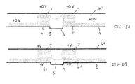
Figs. 5A and 5B illustrate an apparatus; -
Fig. 6 illustrates a method; -
Fig. 7 illustrates an apparatus; -
Fig. 8 illustrates an apparatus; and -
Fig. 9 illustrates a method. - The Figures illustrate an
apparatus 1 comprising: a microfluidic channel 3; anelectromechanical gel 5 provided within the microfluidic channel 3; at least one pair ofelectrodes 7 wherein the pair ofelectrodes 7 is configured to control an electric field across the microfluidic channel 3; wherein the at least one pair ofelectrodes 7 are configured to control the electric field across the microfluidic channel 3 to cause theelectromechanical gel 5 to deform in response to a voltage applied to theelectrodes 7 such that the deformation enablesfluid 21 to be pumped through the microfluidic channel 3. - The apparatus may be a microfluidic pump apparatus for controlling the flow of small volumes of fluid. Examples of the
apparatus 1 may be used in biochemical assays, in the manufacture of small devices such as nano-electronic devices or in any other applications which may require small volumes of fluid to be handled. The volumes of fluid which can be handled with such apparatus may be of the order of µL. -
Figs. 1A and 1B schematically illustrate a cross section through anexample apparatus 1. Theexample apparatus 1 comprises a microfluidic channel 3, anelectromechanical gel 5 and at least one pair ofelectrodes 7. - The same cross section of the
apparatus 1 is illustrated inFigs. 1A and 1B . In the example ofFig. 1A no voltage is applied between theelectrodes 7. In the example ofFig. 1B a voltage is applied across theelectrodes 7. - The microfluidic channel 3 may comprise means for enabling flow of a small volume of fluid. The microfluidic channel 3 may comprise a path which the fluid can flow along. The microfluidic channel 3 may be any suitable size or shape for providing a flow path for a small volume of fluid.
- In the examples of
Figs. 1A and 1B the microfluidic channel 3 comprises a groove in a substrate 9. The substrate 9 may be made of any suitable material such as a polymer, glass, fused silica, silicon or any other material. The groove may be formed using any suitable technique such as chemical etching, printing, deposition or any other suitable technique. - The microfluidic channel 3 has a width W which extends in the x direction as indicated in
Figs. 1A and 1B . The microfluidic channel 3 also has a length which extends in the y direction. In the examples ofFigs. 1A and 1B the y direction extends into the page and so is not illustrated inFigs. 1A and 1B . Theapparatus 1 may be arranged so that fluid can be pumped along the length of the microfluidic channel 3. The length of the microfluidic channel 3 may be larger than the width of the microfluidic channel 3. However, it is to be appreciated that in some examples theapparatus 1 may be designed to have a microfluidic channel 3 with a larger width W than length. - The
electromechanical gel 5 may be provided within the microfluidic channel 3. Theelectromechanical gel 5 may be provided so that at least some of theelectromechanical gel 5 is positioned within the microfluidic channel 3. In the examples ofFigs. 1A and 1B some of theelectromechanical gel 5 extends out of the microfluidic channel 3. The proportion of theelectromechanical gel 5 contained within the microfluidic channel 3 compared to the proportion of theelectromechanical gel 5 extending out of the microfluidic channel 3 may be controlled by the voltage applied by theelectrodes 7. - The
electromechanical gel 5 may comprise any material which may deform or otherwise change shape when a voltage is applied across theelectromechanical gel 5. Theelectromechanical gel 5 may comprise any material which may deform when an electric field is applied to the material. In some examples of the disclosure theelectromechanical gel 5 may comprise polysiloxane. It is to be appreciated that any other suitable material may be used in other examples of the disclosure. - In some examples the material which is used as the
electromechanical gel 5 may be biocompatible. This may be useful in biochemical assay chips or other similar devices. - In some examples the hydrophobicity of the material which is used as the
electromechanical gel 5 may be controlled. In some examples the hydrophobicity of the material which is used as theelectromechanical gel 5 may be reduced or minimized to enable theelectromechanical gel 5 to increase the area of the substrate 9 which is covered by theelectromechanical gel 5 and to reduce the contact angle between theelectromechanical gel 5 and the substrate 9. - The
electromechanical gel 5 may be applied to theapparatus 1 using any suitable means. For instance theelectromechanical gel 5 may be applied to the substrate 9 by depositing theelectromechanical gel 5 by spin coating, by using a squeegee or by dipping the substrate 9 in anelectromechanical gel 5 or by any other suitable means. - The pair of
electrodes 7 may comprise any means which may enable control of an electric field provided across the microfluidic channel 3. In the example ofFigs. 1A and 1B the at least one pair ofelectrodes 7 are configured to provide a voltage across the microfluidic channel 3. Theelectrodes 7 may be arranged so that the voltage may be provided perpendicular, or substantially perpendicular, to the direction of fluid flow through the microfluidic channel 3. - In the examples of
Figs. 1A and 1B the pair ofelectrodes 7 are arranged so that afirst electrode 7 is provided on one side of the microfluidic channel 3 and thesecond electrode 7 is provide on the opposite side of the microfluidic channel 3. Theapparatus 1 may be arranged so that the microfluidic channel 3 is provided between theelectrodes 7. Theelectrodes 7 may be arranged so that there is only a small separation between theelectrodes 7 within the pair of electrodes. In some examples the distance between the twoelectrodes 7 within the pair may be 10µm or approximately 10µm or smaller. It is to be appreciated that other arrangements of electrodes may be used in other examples of the disclosure. - The
electrodes 7 may be made from any suitable material. For instance theelectrodes 7 may be formed from a conductive material such as copper, gold, Indium Tin Oxide or any other suitable material. The electrodes may be printed on the substrate 9. - In the example of
Fig. 1A there is no voltage applied between theelectrodes 7. InFig. 1A there is no applied electric field in theelectromechanical gel 5. Theelectromechanical gel 5 is arranged in a first configuration in which only a small proportion of theelectromechanical gel 5 is positioned within the microfluidic channel 3. The layer of theelectromechanical gel 5 provided within the microfluidic channel 3 is thin so that within the microfluidic channel 3 the upper surface of theelectromechanical gel 5 may be close to the surface of the microfluidic channel 3. - As only a small portion of the
electromechanical gel 5 is provided within the microfluidic channel 3 this provides a cavity 11 within the microfluidic channel 3. The cavity 11 may enable fluid to be positioned within the microfluidic channel 3 and may enable fluid flow along the length of the microfluidic channel 3. - In the example of
Fig. 1B a voltage is applied between theelectrodes 7. InFig. 1B there is now an applied electric field in theelectromechanical gel 5. The applied electric field causes a change in shape of theelectromechanical gel 5. - In
Fig. 1B theelectromechanical gel 5 is now arranged in a second configuration in which a larger proportion of theelectromechanical gel 5 is positioned within the microfluidic channel 3. The proportion of theelectromechanical gel 5 positioned within the microfluidic channel 3 increases when the electric field is applied. The layer of theelectromechanical gel 5 provided within the microfluidic channel 3 in the second configuration is thicker than the layer provided in the first configuration. In the second configuration the upper surface of theelectromechanical gel 5 is separated from the surface of the microfluidic channel 3. - As a larger portion of the
electromechanical gel 5 is provided within the microfluidic channel 3 this provides arestriction 13 within the microfluidic channel 3. Therestriction 13 may restrict the fluid which can be positioned within the microfluidic channel 3 and reduce and/or prevent fluid flow along the length of the microfluidic channel 3. -
Fig. 2 illustrates the electromechanical gel principle which demonstrates how an elastic interface between two materials of different electrical permittivities will deform in the presence of an electric field. This principle may be used to control the shape of theelectromechanical gel 5 by controlling the voltage across the microfluidic channel. - In the example of
Fig. 2 a first material and a second material are illustrated. The first material may be provided overlaying the second material. The first material is provided directly overlaying the second material so that aninterface 23 between the first material and the second material is provided. The first material and the second material have different electrical permittivities. - In examples of the disclosure the second material may be the
electromechanical gel 5. This may have an electrical permittivity of ε2 and an electric field within theelectromechanical gel 5 of E2. - The first material may be the fluid 21 which is to be pumped through the microfluidic channel 3. The second material could be any
suitable fluid 21 such as water, methanol, ethanol, glycol, acetone, glycerol, nitrobenzene or any other suitable material. - The fluid 21 has an electrical permittivity of ε1 and an electric field within the
material 21 of E1. - As the
electromechanical gel 5 and the fluid 21 have different electrical permittivities this causes a force to be applied to theinterface 23 of theelectromechanical gel 5 and the fluid 21 when an electrical field if applied. The force is dependent upon the difference in the electrical permittivities of theelectromechanical gel 5 and thefluid 5. The force may be given by the equation
- As the
electromechanical gel 5 and the fluid 21 are deformable the force F causes deformation of theinterface 23 between them. This means that when an electric field is applied to theelectromechanical gel 5 and the fluid 21 they will change shape. This principle may be used to create a cavity 11 orrestriction 13 within the microfluidic channel 3 as illustrated inFigs. 1A and 1B . -
Fig. 3 schematically illustrates a plan view of anapparatus 1 according to examples of the disclosure. Theapparatus 1 ofFig. 3 comprises a microfluidic channel 3 and anelectromechanical gel 5 as described above in relation toFigs. 1A to 2 . - The
example apparatus 1 ofFig. 3 comprises a plurality of pairs ofelectrodes 7. Theelectrodes 7 may be as described above in relation toFigs. 1A to 2 . Each pair ofelectrodes 7 comprises afirst electrode 7 provided on a first side of the microfluidic channel 3 and asecond electrode 7 provided on the other side of the microfluidic channel 3. Each of the plurality of pairs ofelectrodes 7 may be arranged to control the electric field across the microfluidic channel 3. In theexample apparatus 1 ofFig. 3 Each of the plurality of pairs ofelectrodes 7 may be arranged to provide a voltage across the microfluidic channel 3. Each of the plurality of pairs ofelectrodes 7 may be arranged to provide a voltage across the width W of the microfluidic channel 3 so that the voltage is provided perpendicular to the direction of fluid flow through the microfluidic channel 3. - The plurality of pairs of
electrodes 7 extend along the length L of the microfluidic channel 3. The length L of the microfluidic channel 3 may extend in a direction perpendicular or substantially perpendicular to the width W of the microfluidic channel 3. The pairs ofelectrodes 7 may extend along the direction of flow offluid 21 within the microfluidic channel 3. In the example ofFig. 3 the pairs ofelectrodes 7 extend in the y direction. The arrows 31 indicate the electric field which can result from applying a voltage across a pair ofelectrodes 7. Thearrow 33 indicates the direction offluid 21 flow. - The plurality of pairs of
electrodes 7 may be configured to enable different voltages to be applied at different positions along the length of the microfluidic channel 3. Theelectrodes 7 may be controlled independently of each other so that each pair ofelectrodes 7 can provide a different voltage to other pairs ofelectrodes 7. This enables different electric field strengths to be provided at different positions along the microfluidic channel 3. This allows for cavities 11 andrestrictions 13 to be provided at different points along the length of the microfluidic channel 3. - The
electrodes 7 may be controlled to sequentially apply a time varying voltage. This can be used to change the positions of cavities 11 andrestrictions 13 within the microfluidic channel 3. This may enable fluid 21 to be pumped along the length of the microfluidic channel 3. In some examples theelectrodes 7 may be controlled to enable fluid 21 to be pumped through the microfluidic channel 3 using a peristaltic action. - The dimensions of the microfluidic channel 3 and the spacing of the pairs of
electrodes 7 along the length of the microfluidic channel 3 may be selected in dependence of the volume of fluid which is to be moved. As an example the width W of the microfluidic channel 3 could be approximately 10µm and spacing between the pairs ofelectrodes 7 along the length of the microfluidic channel 3 could be approximately 100µm. The height of the microfluidic channel 3 may be the same or similar to the width of the microfluidic channel 3. This allows the open microfluidic channel 3 to be approximated as a half cylinder with radius of 5µm. If each peristaltic pump action comprises one pair of electrodes providing a cavity 11 and an adjacent pair ofelectrodes 7 providing arestriction 13 then the volume of fluid moved by each pump action may be approximately 0.8µL - In some examples the
apparatus 1 may comprise controlling circuitry which may be configured to control the voltages applied by the pairs ofelectrodes 7 across the microfluidic channel 3.Figs. 5 and6 illustrate example controlling circuitry apparatus which may be used. - The controlling circuitry may be configured to control the magnitude of the electric field which is applied across the microfluidic channel 3. This may enable control of the volume of fluid which is pumped through the microfluidic channel 3.
- The controlling circuitry may control the sequence in which the pairs of
electrodes 7 apply voltages across the microfluidic channel 3. The sequence may be controlled to enable peristaltic motion of the fluid 21 through the microfluidic channel 3. - In some examples the controlling circuitry may also control the strength of the electric field which is applied by the
electrodes 7. This may control the size of the cavities 11 which are created and may be used to control the volume offluid 21 which is moved. - It is to be appreciated that in some examples the
apparatus 1 may comprise features which are not illustrated in the figures. For instance, in some examples theapparatus 1 may comprise a further substrate overlying the microfluidic channel 3. In some examples the further substrate may be transparent to enable fluid and molecules within the microfluidic channel 3 to be viewed. - Any suitable material may be used as the further substrate. In some examples the material used for the further substrate may be selected so that
electromechanical gel 5 has a high affinity to the further substrate. For instance, in examples where theelectromechanical gel 5 comprises polysiloxane the further substrate may comprise glass or any other suitable material. This may enable the microfluidic channel 3 to be sealed. - In some examples a film may be provided between the further substrate and the
electromechanical gel 5. The film may be provided to reduce the affinity between theelectromechanical gel 5 and the further substrate in the region overlaying the microfluidic channel 3. The film may comprise a polysiloxane film. The polysiloxane film may be arranged to have a higher viscosity than theelectromechanical gel 5. This may prevent the polysiloxane film from deforming when the electric field is applied. The polysiloxane film may be bonded to the further substrate. -
Figs. 4A to 4C illustrate anapparatus 1 according to another example of the disclosure. Theexample apparatus 1 ofFigs. 4A to 4C comprise a microfluidic channel 3, anelectromechanical gel 5 and at least one pair ofelectrodes 7. -
Fig. 4A illustrates a plan view of theapparatus 1 andFigs. 4B and 4C schematically illustrate a cross section through theapparatus 1. In the example ofFig. 4B no voltage is applied between theelectrodes 7. In the example ofFig. 4C a voltage is applied between theelectrodes 7. - The
electromechanical gel 5 and the microfluidic channel 3 may be as described above in relation toFigs. 1A to 3 however the plurality of pairs ofelectrodes 7 may be provided in a different configuration. In the example ofFigs. 4A to 4C theapparatus 1 comprisescommon electrodes 45 provided between the pairs ofelectrodes 7. In the example ofFigs. 4A to 4C twocommon electrodes 45 are provided. Thecommon electrodes 45 are provided between the pairs ofelectrodes 7. In the examples ofFigs. 4A to 4C common electrodes 45 are provided either side of the microfluidic channel 3. Thecommon electrodes 45 extend along the length of the microfluidic channel 3 so that the samecommon electrode 45 is provided between a plurality of pairs ofelectrodes 7. - In the example of
Fig. 4A thecommon electrodes 45 are provided on a substrate 9 adjacent to the microfluidic channel 3. It is to be appreciated that other arrangements could be used in other examples of the disclosure. For instance, in some examples the common electrodes could form the microfluidic channel 3. - The
common electrode 45 may be provided at a lower potential than the pairs ofelectrodes 7. The electric field within theelectromechanical gel 5 may be controlled by applying a voltage to the pairs ofelectrodes 7. -
Figs. 4B and 4C illustrate how theelectromechanical gel 5 may be deformed when the electric field across the microfluidic channel 3 is controlled. - In the example of
Fig. 4B there is no voltage applied between theelectrodes 7. InFig. 4B there is no applied electric field in theelectromechanical gel 5. Theelectromechanical gel 5 is arranged in a first configuration in which a large proportion of theelectromechanical gel 5 is positioned within the microfluidic channel 3. A thick layer of theelectromechanical gel 5 is provided within the microfluidic channel 3 in the first configuration so that the upper surface of theelectromechanical gel 5 is separated from the surface of the microfluidic channel 3. This creates arestriction 13 within the microfluidic channel 3. - In the example of
Fig. 4C a voltage is applied between theelectrodes 7. InFig. 4C there is now an applied electric field between thecommon electrode 45 and theelectrode 7. The electric field between thecommon electrodes 45 and theelectrode 7 is greater than the electric field within the microfluidic channel 3. This creates a region on either side of the microfluidic channel 3 which has a higher electric field than the microfluidic channel 3. This change in the effective electric field causes a change in shape of theelectromechanical gel 5. - In the example of
Fig. 4C theelectromechanical gel 5 has deformed so that only a small proportion of theelectromechanical gel 5 is positioned within the microfluidic channel 3. The layer of theelectromechanical gel 5 provided within the microfluidic channel 3 is thin so that within the microfluidic channel 3 the upper surface of theelectromechanical gel 5 may be close to the surface of the microfluidic channel 3. In the example ofFig. 4C theelectromechanical gel 5 may deform to increase the proportion of theelectromechanical gel 5 positioned between thecommon electrode 45 and theelectrodes 7. - In the example of
Fig. 4C only a small portion of theelectromechanical gel 5 is provided within the microfluidic channel 3. This provides a cavity 11 within the microfluidic channel 3 which may enable fluid to be positioned within the microfluidic channel 3 and may enable fluid flow along the length of the microfluidic channel 3. - It is to be appreciated that the
electrodes 7 may be controlled to sequentially apply a time varying voltage. This can be used to change the positions of cavities 11 andrestrictions 13 within the microfluidic channel 3. This may enable fluid 21 to be pumped along the length of the microfluidic channel 3. In some examples theelectrodes 7 may be controlled to enable fluid 21 to be pumped through the microfluidic channel 3 using a peristaltic action. - The examples of
Figs. 4A to 4C differ from the examples ofFigs. 1A to 3 in that inFigs. 4A and 4C therestriction 13 is provided when no voltage is applied and the cavity 11 is provided when the voltage is applied. It is to be appreciated that other arrangements could be used to provide the same or similar effects. For instance, in the example ofFigs. 4A to 4C thecommon electrodes 45 are provided extending along the length of the microfluidic channel 3. In other examples a plurality of lower potential electrodes may be provided. - The arrangement of
Figs. 4A to 4C may reduce electrophoresis effects on the fluid 21 as it is moved along the microfluidic channel 3. - In the above described examples the
electrodes Figs. 1A to 4C theelectrodes Figs. 5A and 5B illustrate anapparatus 1 according to another example of the disclosure in which one ormore electrodes 7 are provided on an overlayingsubstrate 49. - The
example apparatus 1 ofFigs. 5A and 5B comprise a microfluidic channel 3, anelectromechanical gel 5, at least one pair ofelectrodes 7 at least onecommon electrode 45 and an overlyingsubstrate 49. -
Figs. 5A and 5B schematically illustrate a cross section through theapparatus 1. In the example ofFig. 5A no voltage is applied to theelectrodes 7. In the example ofFig. 5B a voltage is applied to theelectrodes 7. - The
electromechanical gel 5 and the microfluidic channel 3 may be as described above in relation toFigs. 1A to 4C . - The
common electrodes 45 may be as described above in relation toFigs. 4A to 4C . Thecommon electrodes 45 may be provided on the same substrate 9 as the microfluidic channel 3. Thecommon electrodes 45 may be provided adjacent to the microfluidic channel 3 and may extend along the length of the microfluidic channel 3. Thecommon electrodes 45 may extend along at least a portion of the length of the microfluidic channel 3 so that the samecommon electrode 45 is provided between a plurality of pairs ofelectrodes 7. - The pairs of
electrodes 7 are provided on the overlayingsubstrate 49. In the example ofFigs. 5A and 5B the pairs ofelectrodes 7 are positioned on the overlayingsubstrate 49 so that they are aligned with thecommon electrodes 7. The pairs ofelectrodes 7 are positioned so that they overlay at least a portion of thecommon electrode 45. - The overlaying
substrate 49 may be made of any suitable material such as a polymer, glass, fused silica, silicon or any other suitable material. The pairs ofelectrodes 7 may be formed on the overlayingsubstrate 49 using any suitable means such as printing or deposition. - The
common electrodes 45 may be provided at a lower potential than the pairs ofelectrodes 7. The electric field within theelectromechanical gel 5 may be controlled by applying a voltage to the pairs ofelectrodes 7. This creates a larger electric field on either side of the microfluidic channel 3 and so controls the electric field across the microfluidic channel 3. -
Figs. 5A and 5B illustrate how theelectromechanical gel 5 may be deformed when the electric field across the microfluidic channel 3 is controlled. - In the example of
Fig. 5A there is no voltage applied between theelectrodes 7 and thecommon electrodes 45. InFig. 5A there is no applied electric field in theelectromechanical gel 5. Theelectromechanical gel 5 is arranged in a first configuration in which a large proportion of theelectromechanical gel 5 is positioned within the microfluidic channel 3 and a small proportion is provided between thecommon electrodes 45 and the pairs ofelectrodes 7. This creates arestriction 13 within the microfluidic channel 3. - In the example of
Fig. 5B a voltage is applied between theelectrodes 7 and thecommon electrodes 45. InFig. 5B there is now an applied electric field between thecommon electrode 45 and theelectrode 7. The electric field between thecommon electrodes 45 and theelectrode 7 is greater than the electric field within the microfluidic channel 3. This creates a region on either side of the microfluidic channel 3 which has a higher electric field than the microfluidic channel 3. This change in the effective electric field causes a change in shape of theelectromechanical gel 5. - In the example of
Fig. 5B theelectromechanical gel 5 has deformed so that only a small proportion of theelectromechanical gel 5 is positioned within the microfluidic channel 3 and a larger proportion is provided between thecommon electrodes 45 and the pairs ofelectrodes 7. This provides a cavity 11 within the microfluidic channel 3 which may enable fluid to be positioned within the microfluidic channel 3 and may enable fluid flow along the length of the microfluidic channel 3. - A time varying voltage may be applied to the
electrodes 7 to control the electric field within the microfluidic channel and control the positions of cavities 11 andrestrictions 13 within the microfluidic channel 3. This may enable fluid 21 to be pumped along the length of the microfluidic channel 3. In some examples theelectrodes 7 may be controlled to enable fluid 21 to be pumped through the microfluidic channel 3 using a peristaltic action. -
Fig. 6 illustrates a method. The example method ofFig. 6 may be used to provide anapparatus 1 as described above. The method comprises, at block 61, providing a microfluidic channel 3 and, atblock 63, providing anelectromechanical gel 5 provided within the microfluidic channel 3. The method also comprises, atblock 65, providing at least one pair ofelectrodes 7 wherein the pair ofelectrodes 7 is configured to control an electric field across the microfluidic channel 3. The at least one pair ofelectrodes 7 are configured to control the electric field across the microfluidic channel 3 to cause theelectromechanical gel 5 to deform in response to a voltage applied to theelectrodes 7 so that the deformation enables fluid 21 to be pumped through the microfluidic channel 3. - It is to be appreciated that the method may be performed in any suitable order. For instance in some examples the method may comprise forming a microfluidic channel 3 on a substrate 9 and then depositing
electrodes 7 on the substrate 9. Theelectromechanical gel 5 may then be deposited over the microfluidic channel 3 and theelectrodes 7. - It is to be appreciated that any suitable method may be used to provide the
example apparatus 1 of the disclosure. -
Fig. 7 schematically illustrates an example apparatus 51 which may be used in implementations of the disclosure. The apparatus 51 illustrated inFig. 7 may be a chip or a chip-set. The apparatus 51 may be configured to control a microfluidic pump apparatus such as theapparatus 1 described above with regards toFigs. 1 to 6 . - The example apparatus 51 comprises controlling
circuitry 53. The controllingcircuitry 53 may provide means for controlling a microfluidic pump. - The controlling
circuitry 53 may comprise one or more controllers. The controllingcircuitry 53 may be implemented using instructions that enable hardware functionality, for example, by using executable computer program instructions in a general-purpose or special-purpose processing circuitry 55 that may be stored on a computer readable storage medium (disk, memory etc) to be executed bysuch processing circuitry 55. - The
processing circuitry 55 may be configured to read from and write tomemory circuitry 57. Theprocessing circuitry 55 may comprise one or more processors. Theprocessing circuitry 55 may also comprise an output interface via which data and/or commands are output by theprocessing circuitry 55 and an input interface via which data and/or commands are input to theprocessing circuitry 55. - The
memory circuitry 57 may be configured to store acomputer program 59 comprising computer program instructions (computer program code 60) that controls the operation of the apparatus 51 when loaded intoprocessing circuitry 55. The computer program instructions, of thecomputer program 59, provide the logic and routines that enables the apparatus 51 to perform the example methods illustrated inFig. 9 . Theprocessing circuitry 55 by reading thememory circuitry 57 is able to load and execute thecomputer program 59. - The apparatus 51 therefore comprises: processing circuitry; 55 and
memory circuitry 57 includingcomputer program code 60; thememory circuitry 57 and thecomputer program code 60 configured to, with theprocessing circuitry 55, cause the apparatus 51 at least to perform: controlling voltages applied by a plurality of pairs ofelectrodes 7 wherein the plurality of pairs ofelectrodes 7 are configured to provide voltages across a microfluidic channel 3 so as to deform anelectromechanical gel 5 within the microfluidic channel 3 and enable fluid to be pumped through the microfluidic channel 3. - The
computer program 59 may arrive at the apparatus 51 via any suitable delivery mechanism. The delivery mechanism may be, for example, a non-transitory computer-readable storage medium, a computer program product, a memory device, a record medium such as a compact disc read-only memory (CD-ROM) or digital versatile disc (DVD), an article of manufacture that tangibly embodies the computer program. The delivery mechanism may be a signal configured to reliably transfer thecomputer program 59. The apparatus may propagate or transmit thecomputer program 59 as a computer data signal. - Although the
memory circuitry 57 is illustrated as a single component in the figures it is to be appreciated that it may be implemented as one or more separate components some or all of which may be integrated/removable and/or may provide permanent/semi-permanent/ dynamic/cached storage. - Although the
processing circuitry 55 is illustrated as a single component in the figures it is to be appreciated that it may be implemented as one or more separate components some or all of which may be integrated/removable. - References to "computer-readable storage medium", "computer program product", "tangibly embodied computer program" etc. or a "controller", "computer", "processor" etc. should be understood to encompass not only computers having different architectures such as single /multi- processor architectures and sequential (Von Neumann)/parallel architectures but also specialized circuits such as field-programmable gate arrays (FPGA), application specific integrated circuits (ASIC), signal processing devices and other processing circuitry. References to computer program, instructions, code etc. should be understood to encompass software for a programmable processor or firmware such as, for example, the programmable content of a hardware device which may comprise instructions for a processor, or configuration settings for a fixed-function device, gate array or programmable logic device etc.
- As used in this application, the term "circuitry" refers to all of the following:
- (a) hardware-only circuit implementations (such as implementations in only analog and/or digital circuitry) and
- (b) to combinations of circuits and software (and/or firmware), such as (as applicable): (i) to a combination of processor(s) or (ii) to portions of processor(s)/software (including digital signal processor(s)), software, and memory(ies) that work together to cause an apparatus, such as a mobile phone or server, to perform various functions) and
- (c) to circuits, such as a microprocessor(s) or a portion of a microprocessor(s), that require software or firmware for operation, even if the software or firmware is not physically present.
- This definition of "circuitry" applies to all uses of this term in this application, including in any claims. As a further example, as used in this application, the term "circuitry" would also cover an implementation of merely a processor (or multiple processors) or portion of a processor and its (or their) accompanying software and/or firmware. The term "circuitry" would also cover, for example and if applicable to the particular claim element, a baseband integrated circuit or applications processor integrated circuit for a mobile phone or a similar integrated circuit in a server, a cellular network device, or other network device.
-
Fig. 8 schematically illustrates an example apparatus 61 which may comprise a chip or chip set as illustrated inFig. 7 . - The controlling
circuitry 53 may be mounted on a substrate 9. A microfluidic channel 3 and plurality ofelectrodes 7 may also be mounted on the substrate 9. The microfluidic channel 3 and plurality ofelectrodes 7 may be as described above in relation toFigs. 1A to 6 . The controllingcircuitry 53 may be configured to provide a control signal to the priority of pairs ofelectrodes 7 to control the electric fields provided by each of the pairs ofelectrodes 7. - In the example of
Fig. 8 only one microfluidic channel 3 is illustrated. It is to be appreciated that a plurality of microfluidic channels 3 may be provided in a single apparatus 61. This may enable larger volumes offluid 21 to be controlled or may be used to enable different types offluid 21 to be controlled. -
Fig. 9 illustrates a method. The method ofFig. 9 may be performed by apparatus 51, 61 such as the apparatus ofFigs. 7 and8 . The method comprises, at block 71 controlling voltages applied by a plurality of pairs ofelectrodes 7 wherein the plurality of pairs ofelectrodes 7 are configured to control an electric field across a microfluidic channel 3 so as to deform anelectromechanical gel 5 within the microfluidic channel 3 and enable fluid to be pumped through the microfluidic channel 3. - The blocks illustrated in
Figs. 6 and9 may represent steps in a method and/or sections of code in thecomputer program 59. The illustration of a particular order to the blocks does not necessarily imply that there is a required or preferred order for the blocks and the order and arrangement of the block may be varied. Furthermore, it may be possible for some blocks to be omitted. - The example methods and
apparatus 1, 51, 61 described above provide the advantage that a microfluidic pump can be fabricated on a single apparatus. The microfluidic pump can be created without any micro-electromechanical systems which may make theapparatus 1 simpler and more cost effective to manufacture. - The term "comprise" is used in this document with an inclusive not an exclusive meaning. That is any reference to X comprising Y indicates that X may comprise only one Y or may comprise more than one Y. If it is intended to use "comprise" with an exclusive meaning then it will be made clear in the context by referring to "comprising only one..." or by using "consisting".
- In this detailed description, reference has been made to various examples. The description of features or functions in relation to an example indicates that those features or functions are present in that example. The use of the term "example" or "for example" or "may" in the text denotes, whether explicitly stated or not, that such features or functions are present in at least the described example, whether described as an example or not, and that they can be, but are not necessarily, present in some of or all other examples. Thus "example", "for example" or "may" refers to a particular instance in a class of examples. A property of the instance can be a property of only that instance or a property of the class or a property of a sub-class of the class that includes some but not all of the instances in the class. It is therefore implicitly disclosed that a feature described with reference to one example but not with reference to another example, can where possible be used in that other example but does not necessarily have to be used in that other example.
- Although embodiments of the present invention have been described in the preceding paragraphs with reference to various examples, it should be appreciated that modifications to the examples given can be made without departing from the scope of the invention as claimed. For instance in the above described examples the
apparatus 1 is configured to act as a pump. In other examples theapparatus 1 could act as a stop or valve or any other suitable device. - Features described in the preceding description may be used in combinations other than the combinations explicitly described.
- Although functions have been described with reference to certain features, those functions may be performable by other features whether described or not.
- Although features have been described with reference to certain embodiments, those features may also be present in other embodiments whether described or not.
- Whilst endeavoring in the foregoing specification to draw attention to those features of the invention believed to be of particular importance it should be understood that the Applicant claims protection in respect of any patentable feature or combination of features hereinbefore referred to and/or shown in the drawings whether or not particular emphasis has been placed thereon.
Claims (15)
- An apparatus comprising:a microfluidic channel;an electromechanical gel provided within the microfluidic channel;at least one pair of electrodes wherein the pair of electrodes is configured to control an electric field across the microfluidic channel;wherein the at least one pair of electrodes are configured to control the electric field across the microfluidic channel to cause the electromechanical gel to deform in response to a voltage applied to the electrodes such that the deformation enables fluid to be pumped through the microfluidic channel.
- An apparatus as claimed in any preceding claim wherein the at least one pair of electrodes is configured to enable the voltage to be provided perpendicular to a direction of fluid flow within the microfluidic channel.
- An apparatus as claimed in any preceding claim wherein the at least one pair of electrodes is configured to provide a voltage across the microfluidic channel.
- An apparatus as claimed in any of claims 1 to 2 wherein the at least one pair of electrodes is configured to provide a voltage close to the microfluidic channel.
- An apparatus as claimed in any preceding claim wherein the apparatus comprises a plurality of pairs of electrodes.
- An apparatus as claimed in claim 5 wherein the plurality of pairs of electrodes extend parallel to a direction of fluid flow within the microfluidic channel.
- An apparatus as claimed in any of claims 5 to 6 wherein the plurality of pairs of electrodes are configured to sequentially apply a voltage across the microfluidic channel.
- An apparatus as claimed in 7 wherein the sequentially applied voltages enable peristaltic pump action through the microfluidic channel.
- An apparatus as claimed in any preceding claim wherein the at least one pair of electrodes are configured so that the electromechanical gel deforms to form a cavity within the microfluidic channel when a voltage is applied to the electrodes.
- An apparatus as claimed in any of claims 1 to 9 wherein the at least one pair of electrodes are configured so that the electromechanical gel deforms to form a restriction within the microfluidic channel when a voltage is applied to the electrodes.
- An apparatus as claimed in any preceding claim further comprising controlling circuitry configured to control the voltages applied by the pairs of electrodes across the microfluidic channel.
- An apparatus as claimed in any preceding claim further comprising a substrate overlaying the microfluidic channel.
- An apparatus as claimed in claim 12 further comprising a film between the substrate and the electromechanical gel wherein the film has a higher viscosity than the electromechanical gel.
- A method comprising:providing a microfluidic channel;providing an electromechanical gel provided within the microfluidic channel;providing at least one pair of electrodes wherein the pair of electrodes is configured to control an electric field across the microfluidic channel;wherein the at least one pair of electrodes are configured to control the electric field across the microfluidic channel to cause the electromechanical gel to deform in response to a voltage applied to the electrodes such that the deformation enables fluid to be pumped through the microfluidic channel.
- A method as claimed in claim 14 wherein the at least one pair of electrodes is configured to enable the voltage to be provided perpendicular to a direction of fluid flow within the microfluidic channel.
Priority Applications (4)
| Application Number | Priority Date | Filing Date | Title |
|---|---|---|---|
| EP14200556.0A EP3040554B1 (en) | 2014-12-30 | 2014-12-30 | Microfluidic pump apparatus and methods |
| US15/540,795 US10598171B2 (en) | 2014-12-30 | 2015-12-21 | Microfluidic pump apparatus and methods |
| CN201580069679.2A CN107110148B (en) | 2014-12-30 | 2015-12-21 | Microfluidic pump devices and methods |
| PCT/FI2015/050913 WO2016107974A1 (en) | 2014-12-30 | 2015-12-21 | Microfluidic pump apparatus and methods |
Applications Claiming Priority (1)
| Application Number | Priority Date | Filing Date | Title |
|---|---|---|---|
| EP14200556.0A EP3040554B1 (en) | 2014-12-30 | 2014-12-30 | Microfluidic pump apparatus and methods |
Publications (2)
| Publication Number | Publication Date |
|---|---|
| EP3040554A1 true EP3040554A1 (en) | 2016-07-06 |
| EP3040554B1 EP3040554B1 (en) | 2018-08-22 |
Family
ID=52278469
Family Applications (1)
| Application Number | Title | Priority Date | Filing Date |
|---|---|---|---|
| EP14200556.0A Active EP3040554B1 (en) | 2014-12-30 | 2014-12-30 | Microfluidic pump apparatus and methods |
Country Status (4)
| Country | Link |
|---|---|
| US (1) | US10598171B2 (en) |
| EP (1) | EP3040554B1 (en) |
| CN (1) | CN107110148B (en) |
| WO (1) | WO2016107974A1 (en) |
Families Citing this family (11)
| Publication number | Priority date | Publication date | Assignee | Title |
|---|---|---|---|---|
| CN111271266B (en) * | 2018-12-05 | 2022-09-02 | 研能科技股份有限公司 | Micro-electromechanical pump module |
| CN111271267B (en) * | 2018-12-05 | 2022-08-09 | 研能科技股份有限公司 | Micro-electromechanical pump module |
| CN111271265B (en) * | 2018-12-05 | 2022-07-29 | 研能科技股份有限公司 | MEMS pump module |
| CN111271268B (en) * | 2018-12-05 | 2022-08-09 | 研能科技股份有限公司 | Micro-electromechanical pump module |
| CN111271269B (en) * | 2018-12-05 | 2022-08-09 | 研能科技股份有限公司 | Micro-electromechanical pump module |
| CN111472963B (en) * | 2019-01-24 | 2022-02-11 | 研能科技股份有限公司 | Micro-electromechanical pump module |
| CN111472965B (en) * | 2019-01-24 | 2022-02-11 | 研能科技股份有限公司 | Micro-electromechanical pump module |
| CN111472964B (en) * | 2019-01-24 | 2022-02-11 | 研能科技股份有限公司 | MEMS pump module |
| CN111472962B (en) * | 2019-01-24 | 2022-02-11 | 研能科技股份有限公司 | Micro-electromechanical pump module |
| CN111502968B (en) * | 2019-01-31 | 2022-06-28 | 研能科技股份有限公司 | MEMS pump module |
| CN116412356A (en) * | 2023-04-10 | 2023-07-11 | 中国地质大学(武汉) | General method for viscous liquid delivery and viscous liquid delivery device |
Citations (10)
| Publication number | Priority date | Publication date | Assignee | Title |
|---|---|---|---|---|
| JPH09287571A (en) * | 1996-04-18 | 1997-11-04 | Fuji Electric Co Ltd | Micro pump |
| US5798600A (en) * | 1994-08-29 | 1998-08-25 | Oceaneering International, Inc. | Piezoelectric pumps |
| US20020013545A1 (en) * | 1998-01-29 | 2002-01-31 | David Soltanpour | Synthetic muscle based diaphragm pump apparatuses |
| WO2006065884A2 (en) * | 2004-12-14 | 2006-06-22 | Mark Banister | Actuator pump system |
| EP1748190A1 (en) * | 2005-07-28 | 2007-01-31 | Ethicon Endo-Surgery, Inc. | Electroactive polymer-based pump |
| US20070128059A1 (en) * | 2005-12-01 | 2007-06-07 | Schlumberger Technology Corporation | Electroactive Polymer Pumping System |
| US7397166B1 (en) * | 2006-04-12 | 2008-07-08 | Pacesetter, Inc. | Electroactive polymer-actuated peristaltic pump and medical lead incorporating such a pump |
| JP2009108769A (en) * | 2007-10-30 | 2009-05-21 | Fuji Xerox Co Ltd | Transport system and transport method |
| WO2013044195A2 (en) * | 2011-09-22 | 2013-03-28 | Parker-Hannifin Corporation | Selp pumping and sensing hose utilizing electroactive polymer strips |
| DE102013009592A1 (en) * | 2013-06-07 | 2014-12-11 | Festo Ag & Co. Kg | Fluid flow control device |
Family Cites Families (8)
| Publication number | Priority date | Publication date | Assignee | Title |
|---|---|---|---|---|
| AU2004316255B2 (en) * | 2003-08-29 | 2009-12-03 | Sri International | Electroactive polymer pre-strain |
| CN101124403A (en) * | 2004-12-14 | 2008-02-13 | 麦德医像公司 | Actuator Pump System |
| JP2009543703A (en) | 2006-07-17 | 2009-12-10 | コーニンクレッカ フィリップス エレクトロニクス エヌ ヴィ | Microfluidic system |
| US8148159B2 (en) | 2006-10-05 | 2012-04-03 | Massachusetts Institute Of Technology | System and methods for stretching polynucleotides |
| WO2010123820A2 (en) * | 2009-04-20 | 2010-10-28 | Kansas State University Research Foundation | Electroactive polymer actuators and their use on microfluidic devices |
| SE534488C2 (en) | 2010-02-22 | 2011-09-06 | Lunavation Ab | A system for electrokinetic flow technology |
| CN102897707B (en) | 2011-07-27 | 2015-07-22 | 国家纳米科学中心 | Fluid device for controlling microtubule movement direction, its preparation method and application |
| US9583257B2 (en) | 2014-07-18 | 2017-02-28 | Nokia Technologies Oy | Microfluidics controlled tunable coil |
-
2014
- 2014-12-30 EP EP14200556.0A patent/EP3040554B1/en active Active
-
2015
- 2015-12-21 CN CN201580069679.2A patent/CN107110148B/en active Active
- 2015-12-21 US US15/540,795 patent/US10598171B2/en active Active
- 2015-12-21 WO PCT/FI2015/050913 patent/WO2016107974A1/en not_active Ceased
Patent Citations (10)
| Publication number | Priority date | Publication date | Assignee | Title |
|---|---|---|---|---|
| US5798600A (en) * | 1994-08-29 | 1998-08-25 | Oceaneering International, Inc. | Piezoelectric pumps |
| JPH09287571A (en) * | 1996-04-18 | 1997-11-04 | Fuji Electric Co Ltd | Micro pump |
| US20020013545A1 (en) * | 1998-01-29 | 2002-01-31 | David Soltanpour | Synthetic muscle based diaphragm pump apparatuses |
| WO2006065884A2 (en) * | 2004-12-14 | 2006-06-22 | Mark Banister | Actuator pump system |
| EP1748190A1 (en) * | 2005-07-28 | 2007-01-31 | Ethicon Endo-Surgery, Inc. | Electroactive polymer-based pump |
| US20070128059A1 (en) * | 2005-12-01 | 2007-06-07 | Schlumberger Technology Corporation | Electroactive Polymer Pumping System |
| US7397166B1 (en) * | 2006-04-12 | 2008-07-08 | Pacesetter, Inc. | Electroactive polymer-actuated peristaltic pump and medical lead incorporating such a pump |
| JP2009108769A (en) * | 2007-10-30 | 2009-05-21 | Fuji Xerox Co Ltd | Transport system and transport method |
| WO2013044195A2 (en) * | 2011-09-22 | 2013-03-28 | Parker-Hannifin Corporation | Selp pumping and sensing hose utilizing electroactive polymer strips |
| DE102013009592A1 (en) * | 2013-06-07 | 2014-12-11 | Festo Ag & Co. Kg | Fluid flow control device |
Also Published As
| Publication number | Publication date |
|---|---|
| US10598171B2 (en) | 2020-03-24 |
| CN107110148B (en) | 2019-08-16 |
| CN107110148A (en) | 2017-08-29 |
| WO2016107974A1 (en) | 2016-07-07 |
| EP3040554B1 (en) | 2018-08-22 |
| US20180003167A1 (en) | 2018-01-04 |
Similar Documents
| Publication | Publication Date | Title |
|---|---|---|
| EP3040554B1 (en) | Microfluidic pump apparatus and methods | |
| Jones et al. | Frequency-dependent electromechanics of aqueous liquids: electrowetting and dielectrophoresis | |
| Verheijen et al. | Reversible electrowetting and trapping of charge: model and experiments | |
| Berthier et al. | Computer aided design of an EWOD microdevice | |
| Swyer et al. | Velocity saturation in digital microfluidics | |
| US8287708B2 (en) | Microfluidic system and method for creating an encapsulated droplet with a removable shell | |
| Zhou et al. | Electrostatic charging and control of droplets in microfluidic devices | |
| US20110056834A1 (en) | Dielectrophoresis-based microfluidic system | |
| CN108885379B (en) | Electrowetting device and manufacturing method of electrowetting device | |
| Brown et al. | Dielectrophoresis-driven spreading of immersed liquid droplets | |
| Hsieh et al. | 3D electrohydrodynamic simulation of electrowetting displays | |
| JP2005140333A (en) | Electrostatic sealing device and method of using the same | |
| Geng et al. | Hybrid electrodes effective for both electrowetting‐and dielectrowetting‐driven digital microfluidics | |
| Liu et al. | Ultralow voltage irreversible electrowetting dynamics of an aqueous drop on a stainless steel surface | |
| Chang et al. | Twin-plate electrowetting for efficient digital microfluidics | |
| Banerjee et al. | Deterministic splitting of fluid volumes in electrowetting microfluidics | |
| CN110601496B (en) | A kind of AC electroosmotic driven ethanol asymmetric micropump and working method | |
| US8771493B2 (en) | Liquid dielectrophoretic device and method for controllably transporting a liquid using the same | |
| JP2016112498A (en) | Liquid droplet driving device | |
| Gwon et al. | Development of a new contactless dielectrophoresis system for active particle manipulation using movable liquid electrodes | |
| Wu et al. | Liquid dielectrophoresis on electret: a novel approach towards CMOS-driven digital microfludics | |
| Mosdorf et al. | Mechanical description of charged droplet motion in electrowetting-on-dielectric experiment and modelling | |
| Lee et al. | Portable particle sorting device based on digital microfluidics utilizing micropillars | |
| Goel et al. | Electric field-dependent scaling law for overdamped (di) electrowetting and dewetting on dielectric | |
| Ishibashi et al. | Two-step perpendicular free-solution isoelectric focusing in a microchamber array chip |
Legal Events
| Date | Code | Title | Description |
|---|---|---|---|
| PUAI | Public reference made under article 153(3) epc to a published international application that has entered the european phase |
Free format text: ORIGINAL CODE: 0009012 |
|
| AK | Designated contracting states |
Kind code of ref document: A1 Designated state(s): AL AT BE BG CH CY CZ DE DK EE ES FI FR GB GR HR HU IE IS IT LI LT LU LV MC MK MT NL NO PL PT RO RS SE SI SK SM TR |
|
| AX | Request for extension of the european patent |
Extension state: BA ME |
|
| STAA | Information on the status of an ep patent application or granted ep patent |
Free format text: STATUS: REQUEST FOR EXAMINATION WAS MADE |
|
| 17P | Request for examination filed |
Effective date: 20161220 |
|
| RBV | Designated contracting states (corrected) |
Designated state(s): AL AT BE BG CH CY CZ DE DK EE ES FI FR GB GR HR HU IE IS IT LI LT LU LV MC MK MT NL NO PL PT RO RS SE SI SK SM TR |
|
| STAA | Information on the status of an ep patent application or granted ep patent |
Free format text: STATUS: EXAMINATION IS IN PROGRESS |
|
| 17Q | First examination report despatched |
Effective date: 20171018 |
|
| GRAP | Despatch of communication of intention to grant a patent |
Free format text: ORIGINAL CODE: EPIDOSNIGR1 |
|
| STAA | Information on the status of an ep patent application or granted ep patent |
Free format text: STATUS: GRANT OF PATENT IS INTENDED |
|
| INTG | Intention to grant announced |
Effective date: 20180525 |
|
| GRAS | Grant fee paid |
Free format text: ORIGINAL CODE: EPIDOSNIGR3 |
|
| GRAA | (expected) grant |
Free format text: ORIGINAL CODE: 0009210 |
|
| STAA | Information on the status of an ep patent application or granted ep patent |
Free format text: STATUS: THE PATENT HAS BEEN GRANTED |
|
| AK | Designated contracting states |
Kind code of ref document: B1 Designated state(s): AL AT BE BG CH CY CZ DE DK EE ES FI FR GB GR HR HU IE IS IT LI LT LU LV MC MK MT NL NO PL PT RO RS SE SI SK SM TR |
|
| REG | Reference to a national code |
Ref country code: GB Ref legal event code: FG4D |
|
| REG | Reference to a national code |
Ref country code: CH Ref legal event code: EP |
|
| REG | Reference to a national code |
Ref country code: DE Ref legal event code: R096 Ref document number: 602014030791 Country of ref document: DE |
|
| REG | Reference to a national code |
Ref country code: AT Ref legal event code: REF Ref document number: 1032843 Country of ref document: AT Kind code of ref document: T Effective date: 20180915 |
|
| REG | Reference to a national code |
Ref country code: IE Ref legal event code: FG4D |
|
| REG | Reference to a national code |
Ref country code: NL Ref legal event code: FP |
|
| REG | Reference to a national code |
Ref country code: LT Ref legal event code: MG4D |
|
| PG25 | Lapsed in a contracting state [announced via postgrant information from national office to epo] |
Ref country code: FI Free format text: LAPSE BECAUSE OF FAILURE TO SUBMIT A TRANSLATION OF THE DESCRIPTION OR TO PAY THE FEE WITHIN THE PRESCRIBED TIME-LIMIT Effective date: 20180822 Ref country code: LT Free format text: LAPSE BECAUSE OF FAILURE TO SUBMIT A TRANSLATION OF THE DESCRIPTION OR TO PAY THE FEE WITHIN THE PRESCRIBED TIME-LIMIT Effective date: 20180822 Ref country code: IS Free format text: LAPSE BECAUSE OF FAILURE TO SUBMIT A TRANSLATION OF THE DESCRIPTION OR TO PAY THE FEE WITHIN THE PRESCRIBED TIME-LIMIT Effective date: 20181222 Ref country code: RS Free format text: LAPSE BECAUSE OF FAILURE TO SUBMIT A TRANSLATION OF THE DESCRIPTION OR TO PAY THE FEE WITHIN THE PRESCRIBED TIME-LIMIT Effective date: 20180822 Ref country code: SE Free format text: LAPSE BECAUSE OF FAILURE TO SUBMIT A TRANSLATION OF THE DESCRIPTION OR TO PAY THE FEE WITHIN THE PRESCRIBED TIME-LIMIT Effective date: 20180822 Ref country code: GR Free format text: LAPSE BECAUSE OF FAILURE TO SUBMIT A TRANSLATION OF THE DESCRIPTION OR TO PAY THE FEE WITHIN THE PRESCRIBED TIME-LIMIT Effective date: 20181123 Ref country code: NO Free format text: LAPSE BECAUSE OF FAILURE TO SUBMIT A TRANSLATION OF THE DESCRIPTION OR TO PAY THE FEE WITHIN THE PRESCRIBED TIME-LIMIT Effective date: 20181122 Ref country code: BG Free format text: LAPSE BECAUSE OF FAILURE TO SUBMIT A TRANSLATION OF THE DESCRIPTION OR TO PAY THE FEE WITHIN THE PRESCRIBED TIME-LIMIT Effective date: 20181122 |
|
| PGFP | Annual fee paid to national office [announced via postgrant information from national office to epo] |
Ref country code: IE Payment date: 20181210 Year of fee payment: 5 |
|
| REG | Reference to a national code |
Ref country code: AT Ref legal event code: MK05 Ref document number: 1032843 Country of ref document: AT Kind code of ref document: T Effective date: 20180822 |
|
| PG25 | Lapsed in a contracting state [announced via postgrant information from national office to epo] |
Ref country code: LV Free format text: LAPSE BECAUSE OF FAILURE TO SUBMIT A TRANSLATION OF THE DESCRIPTION OR TO PAY THE FEE WITHIN THE PRESCRIBED TIME-LIMIT Effective date: 20180822 Ref country code: HR Free format text: LAPSE BECAUSE OF FAILURE TO SUBMIT A TRANSLATION OF THE DESCRIPTION OR TO PAY THE FEE WITHIN THE PRESCRIBED TIME-LIMIT Effective date: 20180822 Ref country code: AL Free format text: LAPSE BECAUSE OF FAILURE TO SUBMIT A TRANSLATION OF THE DESCRIPTION OR TO PAY THE FEE WITHIN THE PRESCRIBED TIME-LIMIT Effective date: 20180822 |
|
| PG25 | Lapsed in a contracting state [announced via postgrant information from national office to epo] |
Ref country code: IT Free format text: LAPSE BECAUSE OF FAILURE TO SUBMIT A TRANSLATION OF THE DESCRIPTION OR TO PAY THE FEE WITHIN THE PRESCRIBED TIME-LIMIT Effective date: 20180822 Ref country code: ES Free format text: LAPSE BECAUSE OF FAILURE TO SUBMIT A TRANSLATION OF THE DESCRIPTION OR TO PAY THE FEE WITHIN THE PRESCRIBED TIME-LIMIT Effective date: 20180822 Ref country code: RO Free format text: LAPSE BECAUSE OF FAILURE TO SUBMIT A TRANSLATION OF THE DESCRIPTION OR TO PAY THE FEE WITHIN THE PRESCRIBED TIME-LIMIT Effective date: 20180822 Ref country code: CZ Free format text: LAPSE BECAUSE OF FAILURE TO SUBMIT A TRANSLATION OF THE DESCRIPTION OR TO PAY THE FEE WITHIN THE PRESCRIBED TIME-LIMIT Effective date: 20180822 Ref country code: PL Free format text: LAPSE BECAUSE OF FAILURE TO SUBMIT A TRANSLATION OF THE DESCRIPTION OR TO PAY THE FEE WITHIN THE PRESCRIBED TIME-LIMIT Effective date: 20180822 Ref country code: AT Free format text: LAPSE BECAUSE OF FAILURE TO SUBMIT A TRANSLATION OF THE DESCRIPTION OR TO PAY THE FEE WITHIN THE PRESCRIBED TIME-LIMIT Effective date: 20180822 Ref country code: EE Free format text: LAPSE BECAUSE OF FAILURE TO SUBMIT A TRANSLATION OF THE DESCRIPTION OR TO PAY THE FEE WITHIN THE PRESCRIBED TIME-LIMIT Effective date: 20180822 |
|
| REG | Reference to a national code |
Ref country code: DE Ref legal event code: R097 Ref document number: 602014030791 Country of ref document: DE |
|
| PG25 | Lapsed in a contracting state [announced via postgrant information from national office to epo] |
Ref country code: DK Free format text: LAPSE BECAUSE OF FAILURE TO SUBMIT A TRANSLATION OF THE DESCRIPTION OR TO PAY THE FEE WITHIN THE PRESCRIBED TIME-LIMIT Effective date: 20180822 Ref country code: SK Free format text: LAPSE BECAUSE OF FAILURE TO SUBMIT A TRANSLATION OF THE DESCRIPTION OR TO PAY THE FEE WITHIN THE PRESCRIBED TIME-LIMIT Effective date: 20180822 Ref country code: SM Free format text: LAPSE BECAUSE OF FAILURE TO SUBMIT A TRANSLATION OF THE DESCRIPTION OR TO PAY THE FEE WITHIN THE PRESCRIBED TIME-LIMIT Effective date: 20180822 |
|
| PLBE | No opposition filed within time limit |
Free format text: ORIGINAL CODE: 0009261 |
|
| STAA | Information on the status of an ep patent application or granted ep patent |
Free format text: STATUS: NO OPPOSITION FILED WITHIN TIME LIMIT |
|
| 26N | No opposition filed |
Effective date: 20190523 |
|
| REG | Reference to a national code |
Ref country code: CH Ref legal event code: PL |
|
| GBPC | Gb: european patent ceased through non-payment of renewal fee |
Effective date: 20181230 |
|
| PG25 | Lapsed in a contracting state [announced via postgrant information from national office to epo] |
Ref country code: LU Free format text: LAPSE BECAUSE OF NON-PAYMENT OF DUE FEES Effective date: 20181230 Ref country code: SI Free format text: LAPSE BECAUSE OF FAILURE TO SUBMIT A TRANSLATION OF THE DESCRIPTION OR TO PAY THE FEE WITHIN THE PRESCRIBED TIME-LIMIT Effective date: 20180822 Ref country code: MC Free format text: LAPSE BECAUSE OF FAILURE TO SUBMIT A TRANSLATION OF THE DESCRIPTION OR TO PAY THE FEE WITHIN THE PRESCRIBED TIME-LIMIT Effective date: 20180822 |
|
| REG | Reference to a national code |
Ref country code: BE Ref legal event code: MM Effective date: 20181231 Ref country code: IE Ref legal event code: MM4A |
|
| PG25 | Lapsed in a contracting state [announced via postgrant information from national office to epo] |
Ref country code: FR Free format text: LAPSE BECAUSE OF NON-PAYMENT OF DUE FEES Effective date: 20181231 Ref country code: IE Free format text: LAPSE BECAUSE OF NON-PAYMENT OF DUE FEES Effective date: 20181230 |
|
| PG25 | Lapsed in a contracting state [announced via postgrant information from national office to epo] |
Ref country code: BE Free format text: LAPSE BECAUSE OF NON-PAYMENT OF DUE FEES Effective date: 20181231 |
|
| PG25 | Lapsed in a contracting state [announced via postgrant information from national office to epo] |
Ref country code: GB Free format text: LAPSE BECAUSE OF NON-PAYMENT OF DUE FEES Effective date: 20181230 Ref country code: CH Free format text: LAPSE BECAUSE OF NON-PAYMENT OF DUE FEES Effective date: 20181231 Ref country code: LI Free format text: LAPSE BECAUSE OF NON-PAYMENT OF DUE FEES Effective date: 20181231 |
|
| PG25 | Lapsed in a contracting state [announced via postgrant information from national office to epo] |
Ref country code: MT Free format text: LAPSE BECAUSE OF NON-PAYMENT OF DUE FEES Effective date: 20181230 |
|
| PG25 | Lapsed in a contracting state [announced via postgrant information from national office to epo] |
Ref country code: TR Free format text: LAPSE BECAUSE OF FAILURE TO SUBMIT A TRANSLATION OF THE DESCRIPTION OR TO PAY THE FEE WITHIN THE PRESCRIBED TIME-LIMIT Effective date: 20180822 |
|
| PG25 | Lapsed in a contracting state [announced via postgrant information from national office to epo] |
Ref country code: PT Free format text: LAPSE BECAUSE OF FAILURE TO SUBMIT A TRANSLATION OF THE DESCRIPTION OR TO PAY THE FEE WITHIN THE PRESCRIBED TIME-LIMIT Effective date: 20180822 |
|
| PG25 | Lapsed in a contracting state [announced via postgrant information from national office to epo] |
Ref country code: MK Free format text: LAPSE BECAUSE OF NON-PAYMENT OF DUE FEES Effective date: 20180822 Ref country code: CY Free format text: LAPSE BECAUSE OF FAILURE TO SUBMIT A TRANSLATION OF THE DESCRIPTION OR TO PAY THE FEE WITHIN THE PRESCRIBED TIME-LIMIT Effective date: 20180822 Ref country code: HU Free format text: LAPSE BECAUSE OF FAILURE TO SUBMIT A TRANSLATION OF THE DESCRIPTION OR TO PAY THE FEE WITHIN THE PRESCRIBED TIME-LIMIT; INVALID AB INITIO Effective date: 20141230 |
|
| REG | Reference to a national code |
Ref country code: NL Ref legal event code: MM Effective date: 20200101 |
|
| PG25 | Lapsed in a contracting state [announced via postgrant information from national office to epo] |
Ref country code: NL Free format text: LAPSE BECAUSE OF NON-PAYMENT OF DUE FEES Effective date: 20200101 |
|
| PGFP | Annual fee paid to national office [announced via postgrant information from national office to epo] |
Ref country code: DE Payment date: 20251104 Year of fee payment: 12 |