EP3040179A2 - Methods of vacuum forming articles of wear - Google Patents
Methods of vacuum forming articles of wear Download PDFInfo
- Publication number
- EP3040179A2 EP3040179A2 EP15194226.5A EP15194226A EP3040179A2 EP 3040179 A2 EP3040179 A2 EP 3040179A2 EP 15194226 A EP15194226 A EP 15194226A EP 3040179 A2 EP3040179 A2 EP 3040179A2
- Authority
- EP
- European Patent Office
- Prior art keywords
- material layer
- wear
- dimensional
- vacuum forming
- article
- Prior art date
- Legal status (The legal status is an assumption and is not a legal conclusion. Google has not performed a legal analysis and makes no representation as to the accuracy of the status listed.)
- Granted
Links
Images













Classifications
-
- B—PERFORMING OPERATIONS; TRANSPORTING
- B29—WORKING OF PLASTICS; WORKING OF SUBSTANCES IN A PLASTIC STATE IN GENERAL
- B29C—SHAPING OR JOINING OF PLASTICS; SHAPING OF MATERIAL IN A PLASTIC STATE, NOT OTHERWISE PROVIDED FOR; AFTER-TREATMENT OF THE SHAPED PRODUCTS, e.g. REPAIRING
- B29C51/00—Shaping by thermoforming, i.e. shaping sheets or sheet like preforms after heating, e.g. shaping sheets in matched moulds or by deep-drawing; Apparatus therefor
- B29C51/10—Forming by pressure difference, e.g. vacuum
-
- B—PERFORMING OPERATIONS; TRANSPORTING
- B32—LAYERED PRODUCTS
- B32B—LAYERED PRODUCTS, i.e. PRODUCTS BUILT-UP OF STRATA OF FLAT OR NON-FLAT, e.g. CELLULAR OR HONEYCOMB, FORM
- B32B37/00—Methods or apparatus for laminating, e.g. by curing or by ultrasonic bonding
- B32B37/10—Methods or apparatus for laminating, e.g. by curing or by ultrasonic bonding characterised by the pressing technique, e.g. using action of vacuum or fluid pressure
- B32B37/1018—Methods or apparatus for laminating, e.g. by curing or by ultrasonic bonding characterised by the pressing technique, e.g. using action of vacuum or fluid pressure using only vacuum
-
- A—HUMAN NECESSITIES
- A43—FOOTWEAR
- A43B—CHARACTERISTIC FEATURES OF FOOTWEAR; PARTS OF FOOTWEAR
- A43B23/00—Uppers; Boot legs; Stiffeners; Other single parts of footwear
- A43B23/02—Uppers; Boot legs
- A43B23/0205—Uppers; Boot legs characterised by the material
- A43B23/0235—Different layers of different material
-
- A—HUMAN NECESSITIES
- A43—FOOTWEAR
- A43B—CHARACTERISTIC FEATURES OF FOOTWEAR; PARTS OF FOOTWEAR
- A43B23/00—Uppers; Boot legs; Stiffeners; Other single parts of footwear
- A43B23/02—Uppers; Boot legs
- A43B23/0245—Uppers; Boot legs characterised by the constructive form
- A43B23/0255—Uppers; Boot legs characterised by the constructive form assembled by gluing or thermo bonding
-
- A—HUMAN NECESSITIES
- A43—FOOTWEAR
- A43B—CHARACTERISTIC FEATURES OF FOOTWEAR; PARTS OF FOOTWEAR
- A43B23/00—Uppers; Boot legs; Stiffeners; Other single parts of footwear
- A43B23/02—Uppers; Boot legs
- A43B23/0245—Uppers; Boot legs characterised by the constructive form
- A43B23/028—Resilient uppers, e.g. shock absorbing
- A43B23/029—Pneumatic upper, e.g. gas filled
-
- B—PERFORMING OPERATIONS; TRANSPORTING
- B29—WORKING OF PLASTICS; WORKING OF SUBSTANCES IN A PLASTIC STATE IN GENERAL
- B29C—SHAPING OR JOINING OF PLASTICS; SHAPING OF MATERIAL IN A PLASTIC STATE, NOT OTHERWISE PROVIDED FOR; AFTER-TREATMENT OF THE SHAPED PRODUCTS, e.g. REPAIRING
- B29C51/00—Shaping by thermoforming, i.e. shaping sheets or sheet like preforms after heating, e.g. shaping sheets in matched moulds or by deep-drawing; Apparatus therefor
- B29C51/006—Shaping by thermoforming, i.e. shaping sheets or sheet like preforms after heating, e.g. shaping sheets in matched moulds or by deep-drawing; Apparatus therefor for making articles having hollow walls
-
- B—PERFORMING OPERATIONS; TRANSPORTING
- B29—WORKING OF PLASTICS; WORKING OF SUBSTANCES IN A PLASTIC STATE IN GENERAL
- B29C—SHAPING OR JOINING OF PLASTICS; SHAPING OF MATERIAL IN A PLASTIC STATE, NOT OTHERWISE PROVIDED FOR; AFTER-TREATMENT OF THE SHAPED PRODUCTS, e.g. REPAIRING
- B29C51/00—Shaping by thermoforming, i.e. shaping sheets or sheet like preforms after heating, e.g. shaping sheets in matched moulds or by deep-drawing; Apparatus therefor
- B29C51/14—Shaping by thermoforming, i.e. shaping sheets or sheet like preforms after heating, e.g. shaping sheets in matched moulds or by deep-drawing; Apparatus therefor using multilayered preforms or sheets
-
- B—PERFORMING OPERATIONS; TRANSPORTING
- B29—WORKING OF PLASTICS; WORKING OF SUBSTANCES IN A PLASTIC STATE IN GENERAL
- B29D—PRODUCING PARTICULAR ARTICLES FROM PLASTICS OR FROM SUBSTANCES IN A PLASTIC STATE
- B29D35/00—Producing footwear
- B29D35/12—Producing parts thereof, e.g. soles, heels, uppers, by a moulding technique
- B29D35/14—Multilayered parts
- B29D35/146—Uppers
-
- B—PERFORMING OPERATIONS; TRANSPORTING
- B32—LAYERED PRODUCTS
- B32B—LAYERED PRODUCTS, i.e. PRODUCTS BUILT-UP OF STRATA OF FLAT OR NON-FLAT, e.g. CELLULAR OR HONEYCOMB, FORM
- B32B37/00—Methods or apparatus for laminating, e.g. by curing or by ultrasonic bonding
- B32B37/14—Methods or apparatus for laminating, e.g. by curing or by ultrasonic bonding characterised by the properties of the layers
-
- B—PERFORMING OPERATIONS; TRANSPORTING
- B32—LAYERED PRODUCTS
- B32B—LAYERED PRODUCTS, i.e. PRODUCTS BUILT-UP OF STRATA OF FLAT OR NON-FLAT, e.g. CELLULAR OR HONEYCOMB, FORM
- B32B38/00—Ancillary operations in connection with laminating processes
-
- B—PERFORMING OPERATIONS; TRANSPORTING
- B29—WORKING OF PLASTICS; WORKING OF SUBSTANCES IN A PLASTIC STATE IN GENERAL
- B29C—SHAPING OR JOINING OF PLASTICS; SHAPING OF MATERIAL IN A PLASTIC STATE, NOT OTHERWISE PROVIDED FOR; AFTER-TREATMENT OF THE SHAPED PRODUCTS, e.g. REPAIRING
- B29C2791/00—Shaping characteristics in general
- B29C2791/004—Shaping under special conditions
- B29C2791/006—Using vacuum
-
- B—PERFORMING OPERATIONS; TRANSPORTING
- B29—WORKING OF PLASTICS; WORKING OF SUBSTANCES IN A PLASTIC STATE IN GENERAL
- B29C—SHAPING OR JOINING OF PLASTICS; SHAPING OF MATERIAL IN A PLASTIC STATE, NOT OTHERWISE PROVIDED FOR; AFTER-TREATMENT OF THE SHAPED PRODUCTS, e.g. REPAIRING
- B29C51/00—Shaping by thermoforming, i.e. shaping sheets or sheet like preforms after heating, e.g. shaping sheets in matched moulds or by deep-drawing; Apparatus therefor
- B29C51/26—Component parts, details or accessories; Auxiliary operations
- B29C51/42—Heating or cooling
- B29C51/421—Heating or cooling of preforms, specially adapted for thermoforming
- B29C51/425—Heating or cooling of preforms, specially adapted for thermoforming using movable heating devices
-
- B—PERFORMING OPERATIONS; TRANSPORTING
- B29—WORKING OF PLASTICS; WORKING OF SUBSTANCES IN A PLASTIC STATE IN GENERAL
- B29K—INDEXING SCHEME ASSOCIATED WITH SUBCLASSES B29B, B29C OR B29D, RELATING TO MOULDING MATERIALS OR TO MATERIALS FOR MOULDS, REINFORCEMENTS, FILLERS OR PREFORMED PARTS, e.g. INSERTS
- B29K2995/00—Properties of moulding materials, reinforcements, fillers, preformed parts or moulds
- B29K2995/0037—Other properties
- B29K2995/0065—Permeability to gases
-
- B—PERFORMING OPERATIONS; TRANSPORTING
- B29—WORKING OF PLASTICS; WORKING OF SUBSTANCES IN A PLASTIC STATE IN GENERAL
- B29K—INDEXING SCHEME ASSOCIATED WITH SUBCLASSES B29B, B29C OR B29D, RELATING TO MOULDING MATERIALS OR TO MATERIALS FOR MOULDS, REINFORCEMENTS, FILLERS OR PREFORMED PARTS, e.g. INSERTS
- B29K2995/00—Properties of moulding materials, reinforcements, fillers, preformed parts or moulds
- B29K2995/0037—Other properties
- B29K2995/0065—Permeability to gases
- B29K2995/0067—Permeability to gases non-permeable
-
- B—PERFORMING OPERATIONS; TRANSPORTING
- B29—WORKING OF PLASTICS; WORKING OF SUBSTANCES IN A PLASTIC STATE IN GENERAL
- B29L—INDEXING SCHEME ASSOCIATED WITH SUBCLASS B29C, RELATING TO PARTICULAR ARTICLES
- B29L2009/00—Layered products
- B29L2009/001—Layered products the layers being loose
-
- B—PERFORMING OPERATIONS; TRANSPORTING
- B29—WORKING OF PLASTICS; WORKING OF SUBSTANCES IN A PLASTIC STATE IN GENERAL
- B29L—INDEXING SCHEME ASSOCIATED WITH SUBCLASS B29C, RELATING TO PARTICULAR ARTICLES
- B29L2031/00—Other particular articles
- B29L2031/48—Wearing apparel
-
- B—PERFORMING OPERATIONS; TRANSPORTING
- B29—WORKING OF PLASTICS; WORKING OF SUBSTANCES IN A PLASTIC STATE IN GENERAL
- B29L—INDEXING SCHEME ASSOCIATED WITH SUBCLASS B29C, RELATING TO PARTICULAR ARTICLES
- B29L2031/00—Other particular articles
- B29L2031/48—Wearing apparel
- B29L2031/50—Footwear, e.g. shoes or parts thereof
-
- B—PERFORMING OPERATIONS; TRANSPORTING
- B29—WORKING OF PLASTICS; WORKING OF SUBSTANCES IN A PLASTIC STATE IN GENERAL
- B29L—INDEXING SCHEME ASSOCIATED WITH SUBCLASS B29C, RELATING TO PARTICULAR ARTICLES
- B29L2031/00—Other particular articles
- B29L2031/48—Wearing apparel
- B29L2031/50—Footwear, e.g. shoes or parts thereof
- B29L2031/505—Uppers
Definitions
- the present invention relates to articles of wear formed using two-dimensional and three-dimensional vacuum forming methods.
- shoe uppers are formed by assembling numerous components, which is a labor-intensive and expensive process. In order to improve the efficiency of shoe manufacturing, efforts have been made to automate this process.
- a cushioning liner may be attached in the inner surface of the three-dimensionally molded part, but this additional step diminishes the efficiencies gained from vacuum molding by re-introducing manual labor back into the manufacturing process.
- vacuum forming may automate certain aspects of the process
- the vacuum forming process typically requires additional manual steps to place the materials into the mold and to remove each material from the mold.
- a method of two-dimensionally forming an article of wear comprises positioning a first side of a first material layer adjacent a one-sided mold comprising cut-out locations, positioning a second material layer adjacent a second side of the first material layer, applying a vacuum to the first side of the first material layer so that the first material layer is molded to the cut-out locations within the one-sided mold, and bonding the second material layer to the first material layer in areas outside the cut-out locations of the one-sided mold.
- the method further comprises applying heat to the first material layer and the second material layer while applying the vacuum to the first side of the first material layer.
- the method may also comprise pre-heating at least the first material layer prior to positioning the first side of the first material layer adjacent the one-sided mold.
- the method may comprise cutting the article of wear out of the first material layer and the second material layer. In further embodiments, the method comprises separating the cut article of wear from the first material layer and the second material layer.
- the first material layer is a non-breathable film
- the second material layer is a breathable material
- the article of wear may comprise a formed plate having air pockets sandwiched between the first material layer and the second material layer.
- the method comprises coupling sides of the formed plate to an upper so that the second material layer is facing a wearer's foot to provide breathability and wicking to the wearer's foot.
- the method may also comprise coupling sides of the formed plate to an upper so that the first material layer is facing a wearer's foot to provide a waterproof upper.
- applying the vacuum to the first side of the first material layer does not cause the second material layer to become molded to the cut-out locations within the one-sided mold.
- the article of wear comprises a generally flat shape with three-dimensional features molded into the first material layer.
- the three-dimensional features may comprise one or more of embossing, de-bossing, and texture features.
- a system for vacuum forming articles of wear comprises a frame supporting a vacuum table comprising a one-sided mold, a seal frame coupled to the frame and positioned above the vacuum table, wherein the seal frame is configured to surround the one-sided mold, and a heating element slidingly coupled to the frame above the seal frame.
- the system further comprises a roller coupled to a pair of tracks positioned in opposing sides of the seal frame.
- the system may also comprise one or more heating elements positioned adjacent the vacuum table.
- the system further comprises a cutting tool mounted to the frame above the vacuum table.
- system further comprises a retrieval device slidingly coupled to the frame.
- a plurality of telescoping arms may be positioned on the retrieval device.
- an article of wear comprises a generally flat shape formed by a first material layer formed of non-breathable material, wherein the first material layer comprises three-dimensional features, and a second material layer formed of breathable material, wherein the second material layer forms a locking layer with the first material layer that maintains a shape of the three-dimensional features when the article of wear is transitioned from the generally flat shape to a three-dimensional structure.
- the second material layer maintains the shape of the three-dimensional features when the article of wear is transitioned from the generally flat shape to the three-dimensional structure by having a low amount of stretch or no stretch.
- the present invention comprises apparel, footwear, sports equipment, and accessories ("articles of wear 10"), in which the articles of wear 10 or components thereof are formed from at least one of a two-dimensional vacuum forming process 12 or a three-dimensional vacuum forming process 14.
- a two-dimensional vacuum forming process 12 or the three-dimensional vacuum forming process 14 may be used to form any suitable wear item or component thereof.
- the first material layer 16 comprises a material that is suitable for being molded via vacuum forming.
- material layer 16 include but are not limited to non-breathable films, synthetic and/or natural leather, various fabrics and meshes, ethylene-vinyl acetate (“EVA”), polyurethane (“PU”), thermoplastic polyurethane (“TPU”), other thermoplastic materials, or any other material having similar properties that are conducive to molding via vacuum forming.
- EVA ethylene-vinyl acetate
- PU polyurethane
- TPU thermoplastic polyurethane
- the second material layer 18 comprises a breathable material, examples of which include but are not limited to mesh, fabric, or other suitable breathable materials having a low amount of stretch or no stretch.
- the second material layer 18 may comprise a breathable material have a limited amount of stretch in certain directions, and no stretch in other directions.
- such materials are described in U.S. Application No. 14/165,468, filed on Jan. 27, 2014 ; U.S. Application No. 14/165,499, filed on Jan. 27, 2014 ; and U.S. Application No. 14/246,740, filed on Apr. 7, 2014 .
- Additional layers that may be included in the two-dimensional vacuum forming process 12 and/or the three-dimensional vacuum forming process 14 include but are not limited to stretchable fabrics, sandwich meshes, woven materials, non-woven materials, and other similar materials. These additional layers may be positioned between the first material layer 16 and the second material layer 18, below the first material layer 16, above the second material layer 18, or any suitable combination thereof.
- Figure 16 illustrates a combination of four material layers that may be used with the two-dimensional vacuum forming process 12 or the three-dimensional vacuum forming process 14, which include the first material layer 16 (which may be a TPU material), the second material layer 18 (which may be an EVA material), a third material layer 20, and a fourth material layer 22.
- the third material layer 20 includes but is not limited to "hot melt”, which is a generic term for heat activated adhesive layers, and other similar materials.
- the fourth material layer 22 includes but is not limited to stretchable fabrics, sandwich meshes, woven materials, non-woven materials, and other similar materials.
- a combination of three material layers 16, 18, 20 may be used with the two-dimensional vacuum forming process 12 or the three-dimensional vacuum forming process 14.
- a person of ordinary skill in the relevant art will understand that any suitable number and combination of layers may be used with the two-dimensional vacuum forming process 12 or the three-dimensional vacuum forming process 14 as needed to achieve the desired properties and performance characteristics of the articles of wear 10.
- the two-dimensional vacuum forming process 12 comprises a pre-heating step 24, a vacuum forming step 26, a heating step 28, a laminating step 30, a cooling step 32, a cutting step 34, and/or a separating step 36.
- At least the first material layer 16 is pre-heated in the pre-heating step 24.
- heating may be achieved by any suitable method. All means of heat transfer (conduction, convection, and radiation) are all reasonably assumed to be viable. In certain embodiments, heat may be applied to the material handling roller by heat-lamp, by steam, friction, or other similar means.
- one or more heating elements 38 may be used to perform the pre-heating step 24.
- a series of strip heaters may be mounted to an aluminum plate or a ceramic plate may be used as one or both of the heating elements 38.
- one heating element 38A is positioned below the first material layer 16, and a second heating element 38B is positioned above the third material layer 20.
- the second heating element 38B may be set to a different temperature than the first heating element 38A, depending on the type of material and the specific material properties of the material layers, and the type of molding design, among other factors.
- the heating elements 38A, 38B are positioned on each side of the first material layer 16, while the other material layers are not subjected to the pre-heating step 24.
- a person of ordinary skill in the relevant art will understand that any suitable number and combination of material layers may be introduced into the pre-heating step 24 as needed or desired to achieve the desired outcome in the later steps of the two-dimensional vacuum forming process 12.
- the desired temperature of at least the first material layer 16 may vary depending on the type of material and the specific material properties of the first material layer 16, and the type of molding design, among other factors.
- the pre-heating step 24 is designed to improve the ability to mold the first material layer 16 during the vacuum forming step 26, while not heating the material layers to a temperature where the second material layer 18 bonds to the first material layer 16 and/or any other intervening material layers.
- the temperature of the first material layer 16 exiting the pre-heating step 24 should not be so high that the first material layer 16 stretches instead of moves, particularly in the case of embodiments that utilize a continuous or semi-continuous two-dimensional vacuum forming process 12 design, as shown in Figures 17-27 .
- One or both heating elements 38A, 38B may be connected to one or more positioning devices 40, such as a pneumatic actuator, which are designed to control the vertical positioning of the heating elements 38.
- the positioning device 40 may be configured to place one or both heating elements 38A, 38B in contact with or within close proximity of the material layers introduced into the pre-heating step 24 for a specified period of time so as to raise the temperature of the material layer or layers to a desired value before applying the vacuum forming step 26.
- the positioning device 40 may be configured to adjust the height of the first heating element 38A over a specified range of travel, while the second heating element 38B remains stationary, or vice versa, or to adjust the height of both elements 38A, 38B over the specified range of travel.
- the specified range of travel is approximately 2 inches, but may be more or less depending on the number of layers, the material thickness, the available space, and other relevant design criteria.
- the layers 16, 18 are then positioned over a one-sided mold 42, which is positioned over a vacuum table 46.
- the layers 16, 18 are arranged so that the first material layer 16 contacts the mold 42, and the second material layer 18 is positioned on the opposing side of the first material layer 16.
- the mold material includes but is not limited to acrylic, ceramic, various metals, other rigid and thermally conductive or non-conductive materials depending on process needs.
- the molds 42 may be cut with a laser cutting tool, a water jet, a computer numerical control (“CNC”) mill, or electrical discharge machining (“EDM”) to provide cut-out locations 44.
- CNC computer numerical control
- EDM electrical discharge machining
- the cut-out locations 44 may be used to generate various effects, shaping, and/or entire components, which include but are not limited to embossing, de-bossing, texture features, liner assemblies, perimeter cutting, and/or perforations.
- various effects, shaping, and/or entire components which include but are not limited to embossing, de-bossing, texture features, liner assemblies, perimeter cutting, and/or perforations.
- multiple material layers of various colors may be used with the cut-out locations 44 in the mold 42 to show the colors of the various material layers in the article of wear 10.
- a vacuum pump 48 which is connected to the vacuum table 46, is activated to supply suction to the mold 42 positioned on the vacuum table 46.
- a booster tank 92 may be included to provide additional suction for the vacuum table 46.
- the suction created by the vacuum pump 48 causes the first material layer 16 to be drawn into the cut-out locations 44 within the mold 42. Because the second material layer 18 is breathable, the suction created by the vacuum pump 48 does not draw the second material layer 18 into the cut-out locations 44 within the mold 42.
- the second material layer 18 is relatively unaffected by the application of vacuum, while the first material layer 16 (and any other non-breathable layers positioned between the first material layer 16 and the second material layer 18) is molded into the cut-out locations 44 and otherwise molded around the shape of the mold 42.
- the vacuum table 46 may be connected to one or more positioning devices 50, such as a pneumatic actuator, that control the vertical positioning of the vacuum table 46.
- the positioning device 50 may be configured to place the mold 42 located on the vacuum table 46 in contact with or within close proximity of the first material layer 16.
- a seal frame 52 may be positioned so as to contact or be within close proximity of the second material layer 18.
- the seal frame 52 may also be coupled to the positioning device 50 or may be mounted in a fixed location.
- the positioning device 50 may be configured to adjust the height of the vacuum table 46 over a specified range of travel, while the seal frame 52 remains stationary, or vice versa, or adjust the height of both the vacuum table 46 and the seal frame 52 over the specified range of travel.
- the specified range of travel is approximately 2 inches, but may be more or less depending on the number of layers, the material thickness, the available space, and other relevant design criteria.
- the material layers are further heated in the heating step 28 while the vacuum forming step 26 is being performed.
- the additional heat from the heating step 28 assists the first material layer 16 in completely shaping to the cut-out locations 44 of the mold 42.
- one or more heating elements 54 may be used to perform the heating step 28.
- a series of strip heaters may be mounted to an aluminum plate or a ceramic plate may be used as one or both of the heating elements 54.
- the desired temperature of the first material layer 16 to be achieved by the heating step 28 will vary depending on the type of material and the specific material properties of the first material layer 16, and the type of molding design, among other factors.
- the heating element 54 is positioned so as to contact or be within close proximity of the second material layer 18.
- the second material layer 18 in turn contacts the first material layer 16 at contact areas 56 on the mold 42 surface where the applied vacuum has not drawn the first material layer 16 into the mold 42 and away from the second material layer 18.
- the heating element 54 may be slidingly coupled to a frame 58 supporting the vacuum table 46 so that the heating element 54 may travel to the proper location above the second material layer 18 when the process is ready for the heating step 28, then return to a recessed position when the heating step 28 is complete.
- the heating element 54 may be further mounted to rails 60 that are substantially aligned with the location of the seal frame 52 so that the heating element 54 is aligned with the portion of the first material layer 16 that is under vacuum.
- the heating element 54 may be connected to one or more positioning devices 62, such as a pneumatic actuator, that control the vertical positioning of the heating element 54.
- the positioning device 62 may be configured to adjust the height of the heating element 54 so that the heating element 54 is placed into contact with or be within close proximity of the second material layer 18. Therefore, the positioning device 62 may be configured to adjust the height of the heating element 54 over a specified range of travel.
- the specified range of travel is approximately 2 inches, but may be more or less depending on the number of layers, the material thickness, the available space, and other relevant design criteria.
- the laminating step 30 is performed after the heating step 28, while the vacuum forming step 26 is still being performed.
- a roller 64 may be used to perform the laminating step 30.
- the roller 64 may be heated to provide additional heat, along with pressure, to bond the first material layer 16 and the second material layer 18 at the contact areas 56 on the mold 42 surface.
- the roller 64 may also be slidingly coupled to the frame 58 supporting the vacuum table 46.
- the roller 64 may be further mounted to rails 66 that are substantially aligned with the location of the seal frame 52 so that the roller 64 is aligned with the portion of the first material layer 16 that is under vacuum.
- the roller 64 may be coupled to a pair of tracks positioned in opposing sides of the seal frame 52.
- the second material layer 18 acts as a locking layer that maintains the shape of the molded first material layer 16 when the article of wear 10 is transitioned from a generally flat shape to a three-dimensional structure.
- the first material layer 16 is molded to have an embossed effect, wherein the embossed material is maintained by the superficial tension created in the first material layer 16 through the vacuum forming step 26 and the laminating step 30.
- the molded material layers may require a cooling step 32, as best illustrated in Figures 17 and 19 .
- the material layers may be cooled by any suitable cooling means, including but not limited to a flow of forced air across the surface (such as via a cooling fan 94), water mist, and/or a combination thereof.
- the bonded layers 16, 18 begin to cool and the cutting step 34 is performed.
- the heating element 54 and the roller 64 slide out of the way so that a laser or die cutting tool 68 mounted to the frame 58 supporting the vacuum table 46 may cut out the two-dimensional embossed article of wear 10 from the surrounding layers 16, 18.
- the cutout articles of wear 10 are separated from the surrounding material layers via the separating step 36.
- the separating step 36 may be performed by a retrieval device 70, which may be slidingly mounted to the frame 58 supporting the vacuum table 46.
- the retrieval device 70 may comprise a plurality of telescoping arms 72 to which suction cups 74 are attached. Once the cutting step 34 is complete, the retrieval device 70 slides into place above the vacuum table 46.
- the arms 72 are positioned on the retrieval device 70 in locations that correspond to the locations of the two-dimensional embossed articles of wear 10 that have been cut away from the surrounding material layers. When the retrieval device 70 is in position above the vacuum table 46, the arms 72 extend until the suction cups 74 attach to the articles of wear 10.
- the arms 72 then retract, which separates the articles of wear 10 from the surrounding material layers.
- a mechanical arm or belt system incorporating suction bellows may also be employed.
- Other machines might employ static electric forces, magnetic forces, tacky surfaces (similar to the tacky surfaces on repositionable notes), micro bonding, hook and loop designs, or other similar designs.
- the retrieval device 70 slides away from the vacuum table 46 and over a collection area 76, where the suction cups 74 then release the articles of wear 10 so that they are collected in a collection device 78, which may be a stationary bin or a conveyor or other device that transports the articles of wear 10 to another suitable location.
- a collection device 78 which may be a stationary bin or a conveyor or other device that transports the articles of wear 10 to another suitable location.
- Figures 1 , 4-6 , 8 , 10 , 12 , 14 , and 15 illustrate various embodiments of articles of wear 10 formed via the two-dimensional vacuum forming process 12.
- the article of wear 10 may be an upper for a sports shoe, as shown in Figures 4-6 , 8 , 10 , 12 , and 14 .
- the article of wear 10 may be designed so that the second material layer 18 is facing the wearer's foot, but may also be used in reverse so that the first material layer 18 is facing the wearer's foot.
- the article of wear 10 is formed with an generally flat shape with three-dimensional features molded into the first material layer 16.
- the three-dimensional features include but are not limited to embossing, de-bossing, and/or texture features.
- the article of wear 10 may also comprise liner assemblies, perimeter cutting, and/or perforations.
- the article of wear 10 may be a vacuum formed base plate or formed plate 80, which is designed to replace a strobel or board lasting plates in conventional shoe designs.
- the plate 80 comprises air pockets 82 sandwiched between the first material layer 16 and the second material layer 18 covering the air pockets 82. This design provides additional cushioning, wicking, and breathability to a wearer's foot when the plate 80 is arranged so that the second material layer 18 is facing the wearer's foot.
- the plate 80 provides additional cushioning and a waterproof upper when the plate 80 is arranged so that the first material layer 16 is facing the wearer's foot.
- the plate 80 may also be assembled to an upper in a fast and cost-efficient manner.
- the upper is adhered or bonded to the sides of the plate 80 via a wheel that moves along the side to join the upper to the sides of the plate 80.
- Figures 28-37 illustrate various embodiments of articles of wear 10 formed via the three-dimensional vacuum forming process 14.
- the same machinery and process steps described above may be used with the three-dimensional vacuum forming process 14, with the following differences.
- the mold may be shaped as a last or a deep draw cavity, among other shapes, whereas for the two-dimensional vacuum forming, the molds are relatively flat, with a height generally of up to 10 mm. For certain embodiments, the height of the mold may exceed 10 mm.
- the second material layer 18 may be positioned between the first material layer 16 and another non-breathable material layer 20 so that the second material layer 18 is also drawn into the cut-out locations 44 of the mold 42 during the vacuum forming step 26.
- a three dimensional article of wear 10 may be formed.
- all of the material layers may be fed through the pre-heating step so that the additional non-breathable material layer 20 is conditioned for molding to the mold 42 in the vacuum forming step.
- the material layers are not adhered to one another when entering the vacuum forming step 26. Rather, the material layers are adjacent one another so that they can slide against each other when molding due to differences in the stretch rates among the materials.
- the laminating step 30 may be eliminated because the materials are bonded to one another within the mold 42, as opposed to using the roller 64 to join the areas of the material layers that are not drawn into the cut-out locations 44 of the mold 42.
- the separating step 36 may require different equipment than the retrieval device 70 as the suction cups 74 may not be configured to readily attach to the three dimensional shape of the articles of wear 10.
- a mechanical arm or belt system incorporating suction bellows may also be employed.
- Other machines might employ static electric forces, magnetic forces, tacky surfaces
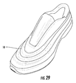
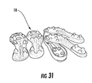
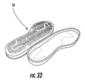
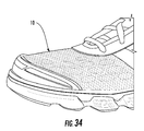
- Figures 28-37 Examples of article of wear 10 formed with the three-dimensional vacuum forming process 14 are shown in Figures 28-37 . As shown in Figures 28-29 and 31-37, these examples include but are not limited to three-dimensional uppers that are formed simultaneously with embossing, de-bossing, texture features, liner assembly, perimeter cutting and/or perforations, cleated plates for football and soccer, outsoles for performance oriented and classic shoes, mid-soles for performance oriented and classic shoes, profiled sock liners, protection pads for football and baseball, internal profile features in the upper to improve fit/comfort/wicking/etc., heel pads for gymnasts, improved comfort and fit ambidextrous soccer shin guards, and/or chest protectors.
- a midsole may be formed of outsole grade EVA so that the midsole may function as both an outsole and a midsole.
- the two-dimensional vacuum forming process 12 and/or the three-dimensional vacuum forming process 14 may be automated so that the layers 16, 18 are pulled through a continuous or semi-continuous process, as opposed to a batch process, as shown in Figures 2-3 .
- a material supply stand 84 may be positioned upstream of the pre-heating step 24.
- at least one roll of material layers may be mounted on the material supply stand 84.
- the material is fed through a pair of push rollers 86 prior to entering the pre-heating step 24.
- the first material layer 16 is fed directly into the pre-heating step 24, while the second material layer 18 by-passes the pre-heating step 24, and the layers 16, 18 are fed through the pair of push rollers 86 positioned after the pre-heating step 24.
- the material layers 16, 18 may be transported from the material supply stand 84 through the two-dimensional vacuum forming process 12 using any suitable device, including but not limited to push rollers, pull rollers, moving pinchers, or any suitable combination thereof.
- the material supply stand 84 is configured to releasably couple and de-couple from the rest of the process so that the material can be easily exchanged as rolls are depleted.
- the surrounding material layers 16, 18 from which the articles of wear 10 were removed may be fed through a pair of pull rollers 88 to assist with pulling the material layers 16, 18 through the process 12. These surrounding material layers 16, 18 may then be collected as scrap or waste by being re-wound into rolls 90 at the end of the process 12, as best illustrated in Figures 17 , 20-21 , and 27 .
- a person of ordinary skill in the art will understand that the material layers 16, 18 may be transported from the material supply stand 84 and through the two-dimensional vacuum forming process 12 using any suitable device, including but not limited to push rollers, pull rollers, moving pinchers, dual belt system, or any suitable combination thereof.
- both the two-dimensional vacuum forming process 12 and the three-dimensional vacuum forming process 14 provide instantly perceived benefits over traditional manufacturing techniques.
- both processes provide added design flexibility, wherein embossing, de-bossing, and various texture effects can be created in one pull.
- the processes also have high productivity, lower tooling costs, and an easier process than conventional manufacturing methods.
- 1 machine as described above may produce 200-400 uppers per hour, and 1 operator may supervise multiple machines.
- the processes also provide for a lighter shoe than conventional manufacturing methods. For example, a direct comparison of the same shoe formed through vacuum forming and conventional methods resulted in a shoe formed by vacuum forming that weighed 40% less than the same shoe formed through conventional methods.
- the vacuum processes may be used with any formable materials including but not limited to EVA, PU, thermoplastic polyurethane ("TPU”), synthetics, leather, nylon, polyester, pebax, polyamides (such as Rilsan®), and other foams, for single or multi-layer construction, etc.
- EVA EVA
- PU thermoplastic polyurethane
- TPU thermoplastic polyurethane
- synthetics leather, nylon, polyester, pebax, polyamides (such as Rilsan®), and other foams, for single or multi-layer construction, etc.
- Additional embodiments of the machinery include a two-dimensional vacuum forming machine for breathable materials utilizing a silicone skin for vacuum forming and bonding, wherein no pre-heating step is required.
- Other embodiments of the machinery include a three-dimensional vacuum forming and compression molding machine.
Landscapes
- Engineering & Computer Science (AREA)
- Mechanical Engineering (AREA)
- Chemical & Material Sciences (AREA)
- Materials Engineering (AREA)
- Physics & Mathematics (AREA)
- Fluid Mechanics (AREA)
- Blow-Moulding Or Thermoforming Of Plastics Or The Like (AREA)
- Physical Vapour Deposition (AREA)
Abstract
Description
- The present invention relates to articles of wear formed using two-dimensional and three-dimensional vacuum forming methods.
- Conventionally, shoe uppers are formed by assembling numerous components, which is a labor-intensive and expensive process. In order to improve the efficiency of shoe manufacturing, efforts have been made to automate this process.
- For example, in certain cases, conventional shoe materials, such as leather, have been replaced by plastic materials, which can be molded into a particular shape using known vacuum forming techniques. In many cases, however, the three-dimensionally formed plastic piece often lacks flexibility which makes the resulting shoe uncomfortable to wear.
- To address the comfort issue, attempts have been made to include a cushioning liner or other soft material between the plastic layers that are then vacuum formed together to form the three-dimensional part. However, because the cushioning layer is not in direct contact with the wearer's foot, the plastic molded shoe continues to lack the desired comfort and flexibility.
- In some cases, a cushioning liner may be attached in the inner surface of the three-dimensionally molded part, but this additional step diminishes the efficiencies gained from vacuum molding by re-introducing manual labor back into the manufacturing process.
- Furthermore, even though vacuum forming may automate certain aspects of the process, the vacuum forming process typically requires additional manual steps to place the materials into the mold and to remove each material from the mold.
- As a result, it may be desirable to provide a manufacturing method that improves manufacturing efficiency by vacuum forming articles of wear as a single piece in a manner that does not introduce new manual steps into the process, while also producing articles of wear that have the desired amount of flexibility and comfort.
- The terms "invention," "the invention," "this invention" and "the present invention" used in this patent are intended to refer broadly to all of the subject matter of this patent and the patent claims below. Statements containing these terms should be understood not to limit the subject matter described herein or to limit the meaning or scope of the patent claims below. Embodiments of the invention covered by this patent are defined by the claims below, not this summary. This summary is a high-level overview of various aspects of the invention and introduces some of the concepts that are further described in the Detailed Description section below. This summary is not intended to identify key or essential features of the claimed subject matter, nor is it intended to be used in isolation to determine the scope of the claimed subject matter. The subject matter should be understood by reference to appropriate portions of the entire specification of this patent, any or all drawings and each claim.
- According to certain embodiments of the present invention, a method of two-dimensionally forming an article of wear comprises positioning a first side of a first material layer adjacent a one-sided mold comprising cut-out locations, positioning a second material layer adjacent a second side of the first material layer, applying a vacuum to the first side of the first material layer so that the first material layer is molded to the cut-out locations within the one-sided mold, and bonding the second material layer to the first material layer in areas outside the cut-out locations of the one-sided mold.
- In some embodiments, the method further comprises applying heat to the first material layer and the second material layer while applying the vacuum to the first side of the first material layer. The method may also comprise pre-heating at least the first material layer prior to positioning the first side of the first material layer adjacent the one-sided mold.
- The method may comprise cutting the article of wear out of the first material layer and the second material layer. In further embodiments, the method comprises separating the cut article of wear from the first material layer and the second material layer.
- According to some embodiments, the first material layer is a non-breathable film, and the second material layer is a breathable material.
- The article of wear may comprise a formed plate having air pockets sandwiched between the first material layer and the second material layer. In some embodiments, the method comprises coupling sides of the formed plate to an upper so that the second material layer is facing a wearer's foot to provide breathability and wicking to the wearer's foot. The method may also comprise coupling sides of the formed plate to an upper so that the first material layer is facing a wearer's foot to provide a waterproof upper.
- In some embodiments, applying the vacuum to the first side of the first material layer does not cause the second material layer to become molded to the cut-out locations within the one-sided mold.
- In some embodiments, the article of wear comprises a generally flat shape with three-dimensional features molded into the first material layer. The three-dimensional features may comprise one or more of embossing, de-bossing, and texture features.
- According to certain embodiments of the present invention, a system for vacuum forming articles of wear comprises a frame supporting a vacuum table comprising a one-sided mold, a seal frame coupled to the frame and positioned above the vacuum table, wherein the seal frame is configured to surround the one-sided mold, and a heating element slidingly coupled to the frame above the seal frame.
- In some embodiments, the system further comprises a roller coupled to a pair of tracks positioned in opposing sides of the seal frame. The system may also comprise one or more heating elements positioned adjacent the vacuum table. In certain embodiments, the system further comprises a cutting tool mounted to the frame above the vacuum table.
- In further embodiments, the system further comprises a retrieval device slidingly coupled to the frame. A plurality of telescoping arms may be positioned on the retrieval device.
- According to certain embodiments of the present invention, an article of wear comprises a generally flat shape formed by a first material layer formed of non-breathable material, wherein the first material layer comprises three-dimensional features, and a second material layer formed of breathable material, wherein the second material layer forms a locking layer with the first material layer that maintains a shape of the three-dimensional features when the article of wear is transitioned from the generally flat shape to a three-dimensional structure.
- In some embodiments, the second material layer maintains the shape of the three-dimensional features when the article of wear is transitioned from the generally flat shape to the three-dimensional structure by having a low amount of stretch or no stretch.
- In the following detailed description, embodiments of the invention are described referring to the following figures:
-
Figure 1 is a perspective view of an article of wear formed by a two-dimensional vacuum forming process, according to certain embodiments of the present invention. -
Figure 2 is a perspective view of a pair of one-sided molds on a vacuum table for use with a two-dimensional vacuum forming process, according to certain embodiments of the present invention. -
Figure 3 is a perspective view of a first material layer being vacuum formed over the pair of one-sided molds by the vacuum table ofFigure 2 , according to certain embodiments of the present invention. -
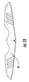
Figure 4 is a top view of an article of wear that is cut and separated from a second material layer laminated to the vacuum-formed first material layer ofFigure 3 , according to certain embodiments of the present invention. -
Figure 5 is a perspective view of a three-dimensional upper formed from the two-dimensional article of wear ofFigure 4 . -
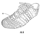
Figure 6 is a perspective view of a shoe formed from the three-dimensional upper ofFigure 5 . -
Figure 7 is a top view of a one-sided mold for use with a two-dimensional vacuum forming process, according to certain embodiments of the present invention. -
Figure 8 is a perspective view of a shoe formed from a two-dimensional article of wear formed with the one-sided mold ofFigure 7 in a two-dimensional vacuum forming process, according to certain embodiments of the present invention. -
Figure 9 is a top view of a one-sided mold for use with a two-dimensional vacuum forming process, according to certain embodiments of the present invention. -
Figure 10 is a perspective view of a shoe formed from a two-dimensional article of wear formed with the one-sided mold ofFigure 9 in a two-dimensional vacuum forming process, according to certain embodiments of the present invention. -
Figure 11 is a top view of a one-sided mold for use with a two-dimensional vacuum forming process, according to certain embodiments of the present invention. -
Figure 12 is a perspective view of a shoe formed from a two-dimensional article of wear formed with the one-sided mold ofFigure 11 in a two-dimensional vacuum forming process, according to certain embodiments of the present invention. -
Figure 13 is a top view of a one-sided mold for use with a two-dimensional vacuum forming process, according to certain embodiments of the present invention. -
Figure 14 is a perspective view of a shoe formed from a two-dimensional article of wear formed with the one-sided mold ofFigure 13 in a two-dimensional vacuum forming process, according to certain embodiments of the present invention. -
Figure 15 is a top view of a one-sided mold for use with a two-dimensional vacuum forming process and a plate formed with the one-sided mold in a two-dimensional vacuum forming process, according to certain embodiments of the present invention. -
Figure 16 is a top view of a material layers for use with a two-dimensional or three-dimensional vacuum forming process, according to certain embodiments of the present invention. -
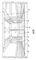
Figure 17 is a schematic of components for performing steps of a two-dimensional vacuum forming process, according to certain embodiments of the present invention. -
Figure 18 is a schematic of components for performing vacuum forming and laminating steps of a two-dimensional vacuum forming process in combination with the other components ofFigures 17 ,19 , and20 , according to certain embodiments of the present invention. -
Figure 19 is a schematic of components for performing steps of a two-dimensional or a three-dimensional vacuum forming process, according to certain embodiments of the present invention. -
Figure 20 is a perspective view of components for performing steps of a two-dimensional or a three-dimensional vacuum forming process, according to certain embodiments of the present invention. -
Figure 21 is a rear perspective view of the components ofFigure 20 . -
Figure 22 is a partial perspective view of the components ofFigure 20 for performing pre-heating, vacuum forming, and heating steps. -
Figure 23 is a partial perspective view of the components ofFigure 20 for performing vacuum forming and laminating steps. -
Figure 24 is a partial perspective view of the components ofFigure 20 for performing cutting and separating steps. -
Figure 25 is a partial perspective view of the components ofFigure 20 performing the separating step to remove articles of wear from the material layers. -
Figure 26 is a partial perspective view of one of the articles of wear ofFigure 25 being held by a retrieval device. -
Figure 27 is another perspective view of the components ofFigure 20 showing the articles of wear ofFigure 25 being transitioned into a collection device. -
Figure 28 is an exploded perspective view of an article of wear formed by a three-dimensional vacuum forming process, according to certain embodiments of the present invention. -
Figure 29 is another perspective view of the article of wear ofFigure 28 . -
Figure 30 is a partial perspective view of components for performing vacuum forming and laminating steps of a three-dimensional vacuum forming process in combination with the other components ofFigures 19 and20 , according to certain embodiments of the present invention. -
Figure 31 is a perspective view of a plurality of articles of wear formed by a three-dimensional vacuum forming process, according to certain embodiments of the present invention. -
Figure 32 is a perspective view of a plurality of articles of wear formed by a three-dimensional vacuum forming process, according to certain embodiments of the present invention. -
Figure 33 is a perspective view of an article of wear formed by a three-dimensional vacuum forming process, according to certain embodiments of the present invention. -
Figure 34 is a partial perspective view of an article of wear formed by a three-dimensional vacuum forming process, according to certain embodiments of the present invention. -
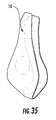
Figure 35 is a perspective view of an article of wear formed by a three-dimensional vacuum forming process, according to certain embodiments of the present invention. -
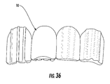
Figure 36 is a perspective view of a plurality of articles of wear formed by a three-dimensional vacuum forming process, according to certain embodiments of the present invention. -
Figure 37 is a perspective view of an article of wear formed by a three-dimensional vacuum forming process, according to certain embodiments of the present invention. - The subject matter of embodiments of the present invention is described here with specificity to meet statutory requirements, but this description is not necessarily intended to limit the scope of the claims. The claimed subject matter may be embodied in other ways, may include different elements or steps, and may be used in conjunction with other existing or future technologies. This description should not be interpreted as implying any particular order or arrangement among or between various steps or elements except when the order of individual steps or arrangement of elements is explicitly described.
- According to certain embodiments, as illustrated in
Figures 1-37 , the present invention comprises apparel, footwear, sports equipment, and accessories ("articles ofwear 10"), in which the articles ofwear 10 or components thereof are formed from at least one of a two-dimensionalvacuum forming process 12 or a three-dimensionalvacuum forming process 14. A person of ordinary skill in the relevant art will understand that the two-dimensionalvacuum forming process 12 or the three-dimensionalvacuum forming process 14 may be used to form any suitable wear item or component thereof. - As best illustrated in
Figures 16-27 , at least one of the material layers 16, 18 is included in the two-dimensionalvacuum forming process 12 and/or the three-dimensionalvacuum forming process 14. Thefirst material layer 16 comprises a material that is suitable for being molded via vacuum forming. Examples ofmaterial layer 16 include but are not limited to non-breathable films, synthetic and/or natural leather, various fabrics and meshes, ethylene-vinyl acetate ("EVA"), polyurethane ("PU"), thermoplastic polyurethane ("TPU"), other thermoplastic materials, or any other material having similar properties that are conducive to molding via vacuum forming. Thesecond material layer 18 comprises a breathable material, examples of which include but are not limited to mesh, fabric, or other suitable breathable materials having a low amount of stretch or no stretch. In certain embodiments, thesecond material layer 18 may comprise a breathable material have a limited amount of stretch in certain directions, and no stretch in other directions. For example, such materials are described inU.S. Application No. 14/165,468, filed on Jan. 27, 2014 U.S. Application No. 14/165,499, filed on Jan. 27, 2014 U.S. Application No. 14/246,740, filed on Apr. 7, 2014 - Additional layers that may be included in the two-dimensional
vacuum forming process 12 and/or the three-dimensionalvacuum forming process 14 include but are not limited to stretchable fabrics, sandwich meshes, woven materials, non-woven materials, and other similar materials. These additional layers may be positioned between thefirst material layer 16 and thesecond material layer 18, below thefirst material layer 16, above thesecond material layer 18, or any suitable combination thereof. For example,Figure 16 illustrates a combination of four material layers that may be used with the two-dimensionalvacuum forming process 12 or the three-dimensionalvacuum forming process 14, which include the first material layer 16 (which may be a TPU material), the second material layer 18 (which may be an EVA material), athird material layer 20, and afourth material layer 22. Thethird material layer 20 includes but is not limited to "hot melt", which is a generic term for heat activated adhesive layers, and other similar materials. Thefourth material layer 22 includes but is not limited to stretchable fabrics, sandwich meshes, woven materials, non-woven materials, and other similar materials. - In other embodiments, as illustrated in
Figure 19 , a combination of threematerial layers vacuum forming process 12 or the three-dimensionalvacuum forming process 14. A person of ordinary skill in the relevant art will understand that any suitable number and combination of layers may be used with the two-dimensionalvacuum forming process 12 or the three-dimensionalvacuum forming process 14 as needed to achieve the desired properties and performance characteristics of the articles ofwear 10. - According to some embodiments, as illustrated in
Figures 17-27 , the two-dimensionalvacuum forming process 12 comprises apre-heating step 24, avacuum forming step 26, aheating step 28, alaminating step 30, a coolingstep 32, a cuttingstep 34, and/or a separatingstep 36. - In these embodiments, as illustrated in
Figures 17 and19-22 , at least thefirst material layer 16 is pre-heated in thepre-heating step 24. A person of ordinary skill in the relevant art will understand that heating may be achieved by any suitable method. All means of heat transfer (conduction, convection, and radiation) are all reasonably assumed to be viable. In certain embodiments, heat may be applied to the material handling roller by heat-lamp, by steam, friction, or other similar means. - In certain embodiments, one or
more heating elements 38 may be used to perform thepre-heating step 24. For example, a series of strip heaters may be mounted to an aluminum plate or a ceramic plate may be used as one or both of theheating elements 38. In some embodiments, as shown inFigure 19 , oneheating element 38A is positioned below thefirst material layer 16, and asecond heating element 38B is positioned above thethird material layer 20. In these embodiments, thesecond heating element 38B may be set to a different temperature than thefirst heating element 38A, depending on the type of material and the specific material properties of the material layers, and the type of molding design, among other factors. - In other embodiments, as shown in
Figures 20-22 , theheating elements first material layer 16, while the other material layers are not subjected to thepre-heating step 24. A person of ordinary skill in the relevant art will understand that any suitable number and combination of material layers may be introduced into the pre-heatingstep 24 as needed or desired to achieve the desired outcome in the later steps of the two-dimensionalvacuum forming process 12. - The desired temperature of at least the
first material layer 16 may vary depending on the type of material and the specific material properties of thefirst material layer 16, and the type of molding design, among other factors. In particular, the pre-heatingstep 24 is designed to improve the ability to mold thefirst material layer 16 during thevacuum forming step 26, while not heating the material layers to a temperature where thesecond material layer 18 bonds to thefirst material layer 16 and/or any other intervening material layers. In addition, the temperature of thefirst material layer 16 exiting the pre-heatingstep 24 should not be so high that thefirst material layer 16 stretches instead of moves, particularly in the case of embodiments that utilize a continuous or semi-continuous two-dimensionalvacuum forming process 12 design, as shown inFigures 17-27 . - One or both
heating elements more positioning devices 40, such as a pneumatic actuator, which are designed to control the vertical positioning of theheating elements 38. In these embodiments, thepositioning device 40 may be configured to place one or bothheating elements step 24 for a specified period of time so as to raise the temperature of the material layer or layers to a desired value before applying thevacuum forming step 26. In certain embodiments, thepositioning device 40 may be configured to adjust the height of thefirst heating element 38A over a specified range of travel, while thesecond heating element 38B remains stationary, or vice versa, or to adjust the height of bothelements - Once the
first material layer 16 and/or thesecond material layer 18 have been pre-heated to the desired temperature, thelayers sided mold 42, which is positioned over a vacuum table 46. In particular, thelayers first material layer 16 contacts themold 42, and thesecond material layer 18 is positioned on the opposing side of thefirst material layer 16. - Examples of one-
sided molds 42 that are used to achieve a variety of types and shapes of articles ofwear 10 are shown inFigures 2 ,7 ,9 ,11 ,13 , and15 . The mold material includes but is not limited to acrylic, ceramic, various metals, other rigid and thermally conductive or non-conductive materials depending on process needs. For example, themolds 42 may be cut with a laser cutting tool, a water jet, a computer numerical control ("CNC") mill, or electrical discharge machining ("EDM") to provide cut-outlocations 44. As shown inFigures 1 ,4-6 ,8 ,10 ,12 ,14 ,15 , the cut-outlocations 44 may be used to generate various effects, shaping, and/or entire components, which include but are not limited to embossing, de-bossing, texture features, liner assemblies, perimeter cutting, and/or perforations. For design variation, as shown inFigures 8 ,10 , and12 , multiple material layers of various colors may be used with the cut-outlocations 44 in themold 42 to show the colors of the various material layers in the article ofwear 10. - Once the material layers 16, 18 are positioned over the
mold 42 and at least a portion of the vacuum table 46, avacuum pump 48, which is connected to the vacuum table 46, is activated to supply suction to themold 42 positioned on the vacuum table 46. In certain embodiments, abooster tank 92 may be included to provide additional suction for the vacuum table 46. The suction created by thevacuum pump 48 causes thefirst material layer 16 to be drawn into the cut-outlocations 44 within themold 42. Because thesecond material layer 18 is breathable, the suction created by thevacuum pump 48 does not draw thesecond material layer 18 into the cut-outlocations 44 within themold 42. Because the material layers are not adhered or otherwise joined to one another at this point in the two-dimensional vacuum forming process, thesecond material layer 18 is relatively unaffected by the application of vacuum, while the first material layer 16 (and any other non-breathable layers positioned between thefirst material layer 16 and the second material layer 18) is molded into the cut-outlocations 44 and otherwise molded around the shape of themold 42. - In certain embodiments, as shown in
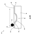
Figure 19 , the vacuum table 46 may be connected to one ormore positioning devices 50, such as a pneumatic actuator, that control the vertical positioning of the vacuum table 46. In these embodiments, thepositioning device 50 may be configured to place themold 42 located on the vacuum table 46 in contact with or within close proximity of thefirst material layer 16. To ensure a proper seal between the vacuum table 46 and thefirst material layer 16, aseal frame 52 may be positioned so as to contact or be within close proximity of thesecond material layer 18. Theseal frame 52 may also be coupled to thepositioning device 50 or may be mounted in a fixed location. Therefore, thepositioning device 50 may be configured to adjust the height of the vacuum table 46 over a specified range of travel, while theseal frame 52 remains stationary, or vice versa, or adjust the height of both the vacuum table 46 and theseal frame 52 over the specified range of travel. According to certain embodiments, the specified range of travel is approximately 2 inches, but may be more or less depending on the number of layers, the material thickness, the available space, and other relevant design criteria. - In some embodiments, as illustrated in
Figures 17 ,19 , and21-22 , the material layers are further heated in theheating step 28 while thevacuum forming step 26 is being performed. The additional heat from theheating step 28 assists thefirst material layer 16 in completely shaping to the cut-outlocations 44 of themold 42. In certain embodiments, one ormore heating elements 54 may be used to perform theheating step 28. For example, a series of strip heaters may be mounted to an aluminum plate or a ceramic plate may be used as one or both of theheating elements 54. - The desired temperature of the
first material layer 16 to be achieved by theheating step 28 will vary depending on the type of material and the specific material properties of thefirst material layer 16, and the type of molding design, among other factors. In some embodiments where the vacuum table 46 is located below themold 42 and thefirst material layer 16, theheating element 54 is positioned so as to contact or be within close proximity of thesecond material layer 18. Thesecond material layer 18 in turn contacts thefirst material layer 16 atcontact areas 56 on themold 42 surface where the applied vacuum has not drawn thefirst material layer 16 into themold 42 and away from thesecond material layer 18. - In certain embodiments, as shown in
Figures 21-22 , theheating element 54 may be slidingly coupled to aframe 58 supporting the vacuum table 46 so that theheating element 54 may travel to the proper location above thesecond material layer 18 when the process is ready for theheating step 28, then return to a recessed position when theheating step 28 is complete. Theheating element 54 may be further mounted torails 60 that are substantially aligned with the location of theseal frame 52 so that theheating element 54 is aligned with the portion of thefirst material layer 16 that is under vacuum. - In certain embodiments, as shown in
Figure 19 , theheating element 54 may be connected to one ormore positioning devices 62, such as a pneumatic actuator, that control the vertical positioning of theheating element 54. In these embodiments, thepositioning device 62 may be configured to adjust the height of theheating element 54 so that theheating element 54 is placed into contact with or be within close proximity of thesecond material layer 18. Therefore, thepositioning device 62 may be configured to adjust the height of theheating element 54 over a specified range of travel. According to certain embodiments, the specified range of travel is approximately 2 inches, but may be more or less depending on the number of layers, the material thickness, the available space, and other relevant design criteria. - In some embodiments, as illustrated in
Figures 17-18 ,21 , and23 , the laminatingstep 30 is performed after theheating step 28, while thevacuum forming step 26 is still being performed. Aroller 64 may be used to perform thelaminating step 30. In some cases, theroller 64 may be heated to provide additional heat, along with pressure, to bond thefirst material layer 16 and thesecond material layer 18 at thecontact areas 56 on themold 42 surface. - The
roller 64 may also be slidingly coupled to theframe 58 supporting the vacuum table 46. In particular, in certain embodiments, theroller 64 may be further mounted torails 66 that are substantially aligned with the location of theseal frame 52 so that theroller 64 is aligned with the portion of thefirst material layer 16 that is under vacuum. In yet other embodiments, theroller 64 may be coupled to a pair of tracks positioned in opposing sides of theseal frame 52. - By bonding the
second material layer 18 to thefirst material layer 16 while thefirst material layer 16 is being held in position against the mold by the applied vacuum, thesecond material layer 18 acts as a locking layer that maintains the shape of the moldedfirst material layer 16 when the article ofwear 10 is transitioned from a generally flat shape to a three-dimensional structure. In other words, thefirst material layer 16 is molded to have an embossed effect, wherein the embossed material is maintained by the superficial tension created in thefirst material layer 16 through thevacuum forming step 26 and thelaminating step 30. - Before the cutting
step 34 is performed, the molded material layers may require a coolingstep 32, as best illustrated inFigures 17 and19 . The material layers may be cooled by any suitable cooling means, including but not limited to a flow of forced air across the surface (such as via a cooling fan 94), water mist, and/or a combination thereof. - Once the
laminating step 30 is complete, the bonded layers 16, 18 begin to cool and the cuttingstep 34 is performed. Theheating element 54 and theroller 64 slide out of the way so that a laser or die cuttingtool 68 mounted to theframe 58 supporting the vacuum table 46 may cut out the two-dimensional embossed article ofwear 10 from the surroundinglayers - In certain embodiments, the cutout articles of
wear 10 are separated from the surrounding material layers via the separatingstep 36. The separatingstep 36 may be performed by aretrieval device 70, which may be slidingly mounted to theframe 58 supporting the vacuum table 46. Theretrieval device 70 may comprise a plurality oftelescoping arms 72 to which suction cups 74 are attached. Once the cuttingstep 34 is complete, theretrieval device 70 slides into place above the vacuum table 46. Thearms 72 are positioned on theretrieval device 70 in locations that correspond to the locations of the two-dimensional embossed articles ofwear 10 that have been cut away from the surrounding material layers. When theretrieval device 70 is in position above the vacuum table 46, thearms 72 extend until thesuction cups 74 attach to the articles ofwear 10. Thearms 72 then retract, which separates the articles ofwear 10 from the surrounding material layers. For part separation/removal, a mechanical arm or belt system incorporating suction bellows may also be employed. Other machines might employ static electric forces, magnetic forces, tacky surfaces (similar to the tacky surfaces on repositionable notes), micro bonding, hook and loop designs, or other similar designs. - Once the
retrieval device 70 has retrieved the articles ofwear 10, theretrieval device 70 slides away from the vacuum table 46 and over acollection area 76, where thesuction cups 74 then release the articles ofwear 10 so that they are collected in acollection device 78, which may be a stationary bin or a conveyor or other device that transports the articles ofwear 10 to another suitable location. -
Figures 1 ,4-6 ,8 ,10 ,12 ,14 , and15 illustrate various embodiments of articles ofwear 10 formed via the two-dimensionalvacuum forming process 12. In certain embodiments, the article ofwear 10 may be an upper for a sports shoe, as shown inFigures 4-6 ,8 ,10 ,12 , and14 . In these embodiments, the article ofwear 10 may be designed so that thesecond material layer 18 is facing the wearer's foot, but may also be used in reverse so that thefirst material layer 18 is facing the wearer's foot. In these embodiments, the article ofwear 10 is formed with an generally flat shape with three-dimensional features molded into thefirst material layer 16. As shown inFigures 1 ,4-6 ,8 , and10 , the three-dimensional features include but are not limited to embossing, de-bossing, and/or texture features. As shown inFigures 4-6 ,8 ,10 ,12 ,14 , and15 , the article ofwear 10 may also comprise liner assemblies, perimeter cutting, and/or perforations. - In other embodiments, the article of
wear 10 may be a vacuum formed base plate or formedplate 80, which is designed to replace a strobel or board lasting plates in conventional shoe designs. As may be seen inFigure 15 , theplate 80 comprisesair pockets 82 sandwiched between thefirst material layer 16 and thesecond material layer 18 covering the air pockets 82. This design provides additional cushioning, wicking, and breathability to a wearer's foot when theplate 80 is arranged so that thesecond material layer 18 is facing the wearer's foot. In other embodiments, theplate 80 provides additional cushioning and a waterproof upper when theplate 80 is arranged so that thefirst material layer 16 is facing the wearer's foot. - The
plate 80 may also be assembled to an upper in a fast and cost-efficient manner. In certain embodiments, the upper is adhered or bonded to the sides of theplate 80 via a wheel that moves along the side to join the upper to the sides of theplate 80. -
Figures 28-37 illustrate various embodiments of articles ofwear 10 formed via the three-dimensionalvacuum forming process 14. In particular, the same machinery and process steps described above may be used with the three-dimensionalvacuum forming process 14, with the following differences. - The primary difference between the two processes is the type of mold utilized. For three-dimensional vacuum forming, as best illustrated in
Figure 30 , the mold may be shaped as a last or a deep draw cavity, among other shapes, whereas for the two-dimensional vacuum forming, the molds are relatively flat, with a height generally of up to 10 mm. For certain embodiments, the height of the mold may exceed 10 mm. - In certain embodiments of three-dimensional vacuum forming, the
second material layer 18 may be positioned between thefirst material layer 16 and anothernon-breathable material layer 20 so that thesecond material layer 18 is also drawn into the cut-outlocations 44 of themold 42 during thevacuum forming step 26. By also molding thesecond material layer 18, a three dimensional article ofwear 10 may be formed. - In the
pre-heating step 24, all of the material layers may be fed through the pre-heating step so that the additionalnon-breathable material layer 20 is conditioned for molding to themold 42 in the vacuum forming step. Like the two-dimensionalvacuum forming process 12, the material layers are not adhered to one another when entering thevacuum forming step 26. Rather, the material layers are adjacent one another so that they can slide against each other when molding due to differences in the stretch rates among the materials. - In the
vacuum forming step 26, to achieve a three dimensional article ofwear 10, differently shapedmolds 42 may be used in the vacuum, as shown inFigure 30 , and the level of vacuum required may differ from the level required for the two-dimensionalvacuum forming process 12. - The
laminating step 30 may be eliminated because the materials are bonded to one another within themold 42, as opposed to using theroller 64 to join the areas of the material layers that are not drawn into the cut-outlocations 44 of themold 42. - The separating
step 36 may require different equipment than theretrieval device 70 as thesuction cups 74 may not be configured to readily attach to the three dimensional shape of the articles ofwear 10. For part separation/removal, a mechanical arm or belt system incorporating suction bellows may also be employed. Other machines might employ static electric forces, magnetic forces, tacky surfaces - (similar to the tacky surfaces on repositionable notes), micro bonding, hook and loop designs, or other similar designs.
- Examples of article of
wear 10 formed with the three-dimensionalvacuum forming process 14 are shown inFigures 28-37 . As shown inFigures 28-29 and 31-37, these examples include but are not limited to three-dimensional uppers that are formed simultaneously with embossing, de-bossing, texture features, liner assembly, perimeter cutting and/or perforations, cleated plates for football and soccer, outsoles for performance oriented and classic shoes, mid-soles for performance oriented and classic shoes, profiled sock liners, protection pads for football and baseball, internal profile features in the upper to improve fit/comfort/wicking/etc., heel pads for gymnasts, improved comfort and fit ambidextrous soccer shin guards, and/or chest protectors. In certain embodiments, a midsole may be formed of outsole grade EVA so that the midsole may function as both an outsole and a midsole. - In certain embodiments, as shown in
Figures 17-27 , the two-dimensionalvacuum forming process 12 and/or the three-dimensionalvacuum forming process 14 may be automated so that thelayers Figures 2-3 . In these embodiments, a material supply stand 84 may be positioned upstream of thepre-heating step 24. As shown inFigures 17 ,19 , and20-21 , at least one roll of material layers may be mounted on thematerial supply stand 84. In some embodiments, the material is fed through a pair ofpush rollers 86 prior to entering thepre-heating step 24. In other embodiments, as shown inFigures 20-21 , thefirst material layer 16 is fed directly into the pre-heatingstep 24, while thesecond material layer 18 by-passes the pre-heatingstep 24, and thelayers push rollers 86 positioned after thepre-heating step 24. A person of ordinary skill in the art will understand that the material layers 16, 18 may be transported from the material supply stand 84 through the two-dimensionalvacuum forming process 12 using any suitable device, including but not limited to push rollers, pull rollers, moving pinchers, or any suitable combination thereof. - Furthermore, in certain embodiments, the material supply stand 84 is configured to releasably couple and de-couple from the rest of the process so that the material can be easily exchanged as rolls are depleted.
- In certain embodiments, as shown in
Figure 19 , following the cuttingstep 34, the surrounding material layers 16, 18 from which the articles ofwear 10 were removed may be fed through a pair ofpull rollers 88 to assist with pulling the material layers 16, 18 through theprocess 12. These surrounding material layers 16, 18 may then be collected as scrap or waste by being re-wound intorolls 90 at the end of theprocess 12, as best illustrated inFigures 17 ,20-21 , and27 . A person of ordinary skill in the art will understand that the material layers 16, 18 may be transported from the material supply stand 84 and through the two-dimensionalvacuum forming process 12 using any suitable device, including but not limited to push rollers, pull rollers, moving pinchers, dual belt system, or any suitable combination thereof. - Use of both the two-dimensional
vacuum forming process 12 and the three-dimensionalvacuum forming process 14 provide instantly perceived benefits over traditional manufacturing techniques. For example, both processes provide added design flexibility, wherein embossing, de-bossing, and various texture effects can be created in one pull. The processes also have high productivity, lower tooling costs, and an easier process than conventional manufacturing methods. For example, 1 machine as described above may produce 200-400 uppers per hour, and 1 operator may supervise multiple machines. - The processes also provide for a lighter shoe than conventional manufacturing methods. For example, a direct comparison of the same shoe formed through vacuum forming and conventional methods resulted in a shoe formed by vacuum forming that weighed 40% less than the same shoe formed through conventional methods.
- The vacuum processes may be used with any formable materials including but not limited to EVA, PU, thermoplastic polyurethane ("TPU"), synthetics, leather, nylon, polyester, pebax, polyamides (such as Rilsan®), and other foams, for single or multi-layer construction, etc.
- Additional embodiments of the machinery include a two-dimensional vacuum forming machine for breathable materials utilizing a silicone skin for vacuum forming and bonding, wherein no pre-heating step is required.
- Other embodiments of the machinery include a three-dimensional vacuum forming and compression molding machine.
- In the following, further embodiments are described to facilitate the understanding of the invention:
- 1. A method of two-dimensionally forming an article of wear comprising:
- positioning a first side of a first material layer adjacent a one-sided mold comprising cut-out locations;
- positioning a second material layer adjacent a second side of the first material layer;
- applying a vacuum to the first side of the first material layer so that the first material layer is molded to the cut-out locations within the one-sided mold; and
- bonding the second material layer to the first material layer in areas outside the cut-out locations of the one-sided mold.
- 2. The method of embodiment 1, wherein the method further comprises applying heat to the first material layer and the second material layer while applying the vacuum to the first side of the first material layer.
- 3. The method of any preceding embodiment, wherein the method further comprises pre-heating at least the first material layer prior to positioning the first side of the first material layer adjacent the one-sided mold.
- 4. The method of any preceding embodiment, wherein the method further comprises cutting the article of wear out of the first material layer and the second material layer.
- 5. The method of any preceding embodiment, wherein the method further comprises separating the cut article of wear from the first material layer and the second material layer.
- 6. The method of any preceding embodiment, wherein the first material layer is a non-breathable film, and the second material layer is a breathable material.
- 7. The method of any preceding embodiment, wherein the article of wear comprises a formed plate having air pockets sandwiched between the first material layer and the second material layer.
- 8. The method of any preceding embodiment, the method further comprising coupling sides of the formed plate to an upper so that the second material layer is facing a wearer's foot to provide breathability and wicking to the wearer's foot.
- 9. The method of any preceding embodiment, the method further comprising coupling sides of the formed plate to an upper so that the first material layer is facing a wearer's foot to provide a waterproof upper.
- 10. The method of any preceding embodiment, wherein applying the vacuum to the first side of the first material layer does not cause the second material layer to become molded to the cut-out locations within the one-sided mold.
- 11. The method of any preceding embodiment, wherein the article of wear comprises a generally flat shape with three-dimensional features molded into the first material layer.
- 12. The method of any preceding embodiment, wherein the three-dimensional features comprise one or more of embossing, de-bossing, and texture features.
- 13. A system for vacuum forming articles of wear comprising:
- a frame supporting a vacuum table comprising a one-sided mold;
- a seal frame coupled to the frame and positioned above the vacuum table, wherein the seal frame is configured to surround the one-sided mold; and
- a heating element slidingly coupled to the frame above the seal frame.
- 14. The system of embodiment 13, further comprising a roller coupled to a pair of tracks positioned in opposing sides of the seal frame.
- 15. The system of
embodiment 13 or 14, further comprising one or more heating elements positioned adjacent the vacuum table. - 16. The system of any of embodiments 13-15, further comprising a cutting tool mounted to the frame above the vacuum table.
- 17. The system of any of embodiments 13-16, further comprising a retrieval device slidingly coupled to the frame.
- 18. The system of embodiment 17, further comprising a plurality of telescoping arms positioned on the retrieval device.
- 19. An article of wear comprising a generally flat shape formed by:
- a first material layer formed of non-breathable material, wherein the first material layer comprises three-dimensional features; and
- a second material layer formed of breathable material, wherein the second material layer forms a locking layer with the first material layer that maintains a shape of the three-dimensional features when the article of wear is transitioned from the generally flat shape to a three-dimensional structure.
- 20. The article of wear of embodiment 19, wherein the second material layer maintains the shape of the three-dimensional features when the article of wear is transitioned from the generally flat shape to the three-dimensional structure by having a low amount of stretch or no stretch.
- Different arrangements of the components depicted in the drawings or described above, as well as components and steps not shown or described are possible. Similarly, some features and sub-combinations are useful and may be employed without reference to other features and sub-combinations. Embodiments of the invention have been described for illustrative and not restrictive purposes, and alternative embodiments will become apparent to readers of this patent. Accordingly, the present invention is not limited to the embodiments described above or depicted in the drawings, and various embodiments and modifications may be made without departing from the scope of the claims below.
Claims (15)
- A method of two-dimensionally forming an article of wear comprising:positioning a first side of a first material layer adjacent a one-sided mold comprising cut-out locations;positioning a second material layer adjacent a second side of the first material layer;applying a vacuum to the first side of the first material layer so that the first material layer is molded to the cut-out locations within the one-sided mold; andbonding the second material layer to the first material layer in areas outside the cut-out locations of the one-sided mold.
- The method of claim 1, wherein the method further comprises pre-heating at least the first material layer prior to positioning the first side of the first material layer adjacent the one-sided mold.
- The method of claim 1 or 2, wherein the first material layer is a non-breathable film, and the second material layer is a breathable material.
- The method of any of the preceding claims, wherein the article of wear comprises a formed plate having air pockets sandwiched between the first material layer and the second material layer.
- The method of claim 4, the method further comprising coupling sides of the formed plate to an upper so that the second material layer is facing a wearer's foot to provide breathability and wicking to the wearer's foot.
- The method of claim 4, the method further comprising coupling sides of the formed plate to an upper so that the first material layer is facing a wearer's foot to provide a waterproof upper.
- The method of any of the preceding claims, wherein applying the vacuum to the first side of the first material layer does not cause the second material layer to become molded to the cut-out locations within the one-sided mold.
- A system for vacuum forming articles of wear comprising:a frame supporting a vacuum table comprising a one-sided mold;a seal frame coupled to the frame and positioned above the vacuum table, wherein the seal frame is configured to surround the one-sided mold; anda heating element slidingly coupled to the frame above the seal frame.
- The system of claim 8, further comprising a roller coupled to a pair of tracks positioned in opposing sides of the seal frame.
- The system of claim 8 or 9, further comprising one or more heating elements positioned adjacent the vacuum table.
- The system of any of the claim 8 - 10, further comprising a cutting tool mounted to the frame above the vacuum table.
- The system of any of the claims 8 - 11, further comprising a retrieval device slidingly coupled to the frame.
- The system of claim 12, further comprising a plurality of telescoping arms positioned on the retrieval device.
- An article of wear comprising a generally flat shape formed by:a first material layer formed of non-breathable material, wherein the first material layer comprises three-dimensional features; anda second material layer formed of breathable material, wherein the second material layer forms a locking layer with the first material layer that maintains a shape of the three-dimensional features when the article of wear is transitioned from the generally flat shape to a three-dimensional structure.
- The article of wear of claim 14, wherein the second material layer maintains the shape of the three-dimensional features when the article of wear is transitioned from the generally flat shape to the three-dimensional structure by having a low amount of stretch or no stretch.
Applications Claiming Priority (1)
| Application Number | Priority Date | Filing Date | Title |
|---|---|---|---|
| US14/540,451 US9789644B2 (en) | 2014-11-13 | 2014-11-13 | Methods of vacuum forming articles of wear |
Publications (3)
| Publication Number | Publication Date |
|---|---|
| EP3040179A2 true EP3040179A2 (en) | 2016-07-06 |
| EP3040179A3 EP3040179A3 (en) | 2016-10-12 |
| EP3040179B1 EP3040179B1 (en) | 2021-03-17 |
Family
ID=54542046
Family Applications (1)
| Application Number | Title | Priority Date | Filing Date |
|---|---|---|---|
| EP15194226.5A Active EP3040179B1 (en) | 2014-11-13 | 2015-11-12 | Methods of vacuum forming articles of wear |
Country Status (3)
| Country | Link |
|---|---|
| US (2) | US9789644B2 (en) |
| EP (1) | EP3040179B1 (en) |
| CN (1) | CN105599422B (en) |
Cited By (1)
| Publication number | Priority date | Publication date | Assignee | Title |
|---|---|---|---|---|
| US12018411B2 (en) | 2021-05-10 | 2024-06-25 | Under Armour, Inc. | Method of forming an upper for an article of footwear |
Families Citing this family (21)
| Publication number | Priority date | Publication date | Assignee | Title |
|---|---|---|---|---|
| US9901138B2 (en) | 2014-11-13 | 2018-02-27 | Adidas Ag | Multilayered materials with color changing properties |
| US11350701B2 (en) | 2015-10-09 | 2022-06-07 | Adidas Ag | Laceless shoe |
| DE102015219636B4 (en) | 2015-10-09 | 2023-11-23 | Adidas Ag | Manufacturing process for coating a fabric with a three-dimensional shape |
| US11758979B2 (en) | 2015-10-09 | 2023-09-19 | Adidas Ag | Shoe |
| DE102015219614B4 (en) | 2015-10-09 | 2025-06-18 | Adidas Ag | Laceless shoe |
| US11297902B2 (en) | 2016-10-03 | 2022-04-12 | Adidas Ag | Laceless shoe |
| US10308779B2 (en) * | 2015-10-30 | 2019-06-04 | Nike, Inc. | Method of foaming a milled precursor |
| ITUB20155474A1 (en) | 2015-11-11 | 2017-05-11 | Nike Innovate Cv | EQUIPMENT, AND ITS PROCEDURE, FOR THE THERMAL TREATMENT OF FOOTWEAR, IN PARTICULAR SPORTS SHOES |
| US10046551B1 (en) * | 2017-07-05 | 2018-08-14 | Sian-De Wei | Recycling method for detaching the cloth material from the E.V.A. insole residual product |
| KR102359402B1 (en) * | 2017-11-17 | 2022-02-08 | 주식회사 쿠라레 | Manufacturing method of sheet molded body |
| TWI722417B (en) | 2018-04-25 | 2021-03-21 | 荷蘭商耐克創新有限合夥公司 | System and methods for preparing article for thermoforming |
| TWI728340B (en) | 2018-04-25 | 2021-05-21 | 荷蘭商耐克創新有限合夥公司 | System and methods for thermoforming articles |
| HUP1800162A2 (en) * | 2018-05-16 | 2019-12-30 | Laszlo Oroszi | Streaked pattern for sports shoes aiding ball technique |
| CN115998052B (en) * | 2018-05-18 | 2026-03-10 | 耐克创新有限合伙公司 | System and method for thermoforming an article |
| USD838952S1 (en) * | 2018-05-21 | 2019-01-29 | Nike, Inc. | Shoe |
| USD839568S1 (en) * | 2018-05-21 | 2019-02-05 | Nike, Inc. | Shoe |
| USD839564S1 (en) * | 2018-05-21 | 2019-02-05 | Nike, Inc. | Shoe |
| USD839565S1 (en) * | 2018-05-31 | 2019-02-05 | Nike, Inc. | Shoe |
| DE102020132404A1 (en) * | 2020-12-07 | 2022-06-09 | Otto Bock Mobility Solutions Gmbh | Method of making a pillow and pillow |
| IT202300004854A1 (en) * | 2023-03-15 | 2024-09-15 | Zhong Qiang Yi Tech Co Ltd | METHOD OF MANUFACTURING SHOE UPPERS |
| FR3146789B1 (en) * | 2023-03-23 | 2025-08-22 | Zhong Qiang Yi Tech Co Ltd | PROCESS FOR MANUFACTURING SHOE UPPERS |
Family Cites Families (82)
| Publication number | Priority date | Publication date | Assignee | Title |
|---|---|---|---|---|
| US2069083A (en) | 1932-10-26 | 1937-01-26 | Us Rubber Co | Shoe with elastic portion |
| US2147197A (en) | 1936-11-25 | 1939-02-14 | Hood Rubber Co Inc | Article of footwear |
| US2582298A (en) | 1949-10-01 | 1952-01-15 | Secotan Inc | Formed shoe uppers and the like |
| US3007262A (en) | 1960-03-09 | 1961-11-07 | Genesco Inc | Shoe construction |
| US3231454A (en) * | 1961-04-14 | 1966-01-25 | Cadillac Products | Cushioning material |
| JPS4510357Y1 (en) | 1965-08-13 | 1970-05-13 | ||
| CA951863A (en) | 1969-11-20 | 1974-07-30 | Keith G. Wyness | Shoe making |
| US3769723A (en) | 1972-12-14 | 1973-11-06 | M Wilbert | Athletic footwear |
| GB1442343A (en) | 1973-10-12 | 1976-07-14 | Lucky Bel Hoes Co Ltd | Shoes |
| US3931685A (en) | 1974-11-15 | 1976-01-13 | Laukaitis Hubert T | Laceless elastic-topped athletic shoe |
| GB1581999A (en) | 1976-07-07 | 1980-12-31 | Drew J A | Orthopaedic footwear |
| US4356642A (en) | 1980-08-27 | 1982-11-02 | Shephard Herman | Support device |
| JPS60242040A (en) * | 1984-05-16 | 1985-12-02 | Mitsubishi Yuka Badische Kk | Production of shock-absorbing laminate material |
| ES1000165Y (en) | 1987-03-18 | 1989-02-01 | Merino Ciudad Ana Isabel | SPORTS SHOES |
| US4893418A (en) * | 1988-01-11 | 1990-01-16 | Ogden Inc. | Shoe insole and method of manufacture |
| JPH022125A (en) | 1988-06-14 | 1990-01-08 | Nec Yamagata Ltd | Formation of through hole of semiconductor device |
| JPH0352665A (en) | 1989-07-17 | 1991-03-06 | Mita Ind Co Ltd | Coating solution storage tank and inlet pipe in coating solution circulating system |
| JP2976252B2 (en) | 1990-11-01 | 1999-11-10 | 日本電気株式会社 | Coefficient control method and apparatus for adaptive filter and method and apparatus for noise removal |
| US5572804A (en) | 1991-09-26 | 1996-11-12 | Retama Technology Corp. | Shoe sole component and shoe sole component construction method |
| US5275775A (en) | 1991-10-21 | 1994-01-04 | Riecken George C | Method for making an insole |
| CA2070274C (en) | 1992-06-02 | 1997-02-11 | Robert Garfield Burke | Shoe insole for foot rehabilitation |
| US5617650A (en) | 1992-10-23 | 1997-04-08 | Grim; Tracy E. | Vacuum formed conformable shoe |
| US5392534A (en) | 1992-10-23 | 1995-02-28 | Grim; Tracy E. | Vacuum formed conformable shoe |
| JP3052665B2 (en) | 1993-01-26 | 2000-06-19 | 株式会社日立製作所 | Flow cell device |
| JPH0740486A (en) | 1993-07-30 | 1995-02-10 | Kuraray Co Ltd | Laminated body and manufacturing method thereof |
| US5529826A (en) | 1994-02-15 | 1996-06-25 | Tailor; Dilip K. | Fabric-faced thermoplastic composite panel |
| US5555650A (en) | 1994-05-27 | 1996-09-17 | Longbottom; Mark A. | Laceless athletic shoe |
| US5940991A (en) | 1995-04-07 | 1999-08-24 | Performance Materials Corporation | Non-planar article formed from thermoplastic composite material and method of forming non-planar article |
| US5879614A (en) | 1996-05-24 | 1999-03-09 | Harrison; Craig M. | Methods of producing waterproof felted material |
| AU744099B2 (en) | 1996-10-10 | 2002-02-14 | Procter & Gamble Company, The | Breathable elastic polymeric film laminates |
| US5797200A (en) | 1996-11-15 | 1998-08-25 | Redwood Sportswear Ltd. | Shoe with stretchable top |
| US5987778A (en) | 1997-01-30 | 1999-11-23 | Stoner; Ronald N. | Protective footwear and lower leg covering |
| AU5104899A (en) | 1998-12-22 | 2000-07-12 | Reebok International Ltd. | An article of footwear and method for making the same |
| US6558784B1 (en) | 1999-03-02 | 2003-05-06 | Adc Composites, Llc | Composite footwear upper and method of manufacturing a composite footwear upper |
| US20020078591A1 (en) | 2000-12-27 | 2002-06-27 | Ballet Makers, Inc. | Dance shoe with tri-split |
| DE10222897B4 (en) | 2002-05-23 | 2017-10-26 | Adidas International Marketing B.V. | shoe |
| US7089690B2 (en) | 2002-05-29 | 2006-08-15 | Nike, Inc. | Material having compressible projections and footwear incorporating the material |
| US7080467B2 (en) | 2003-06-27 | 2006-07-25 | Reebok International Ltd. | Cushioning sole for an article of footwear |
| US7178267B2 (en) | 2003-12-12 | 2007-02-20 | Polyworks, Inc. | Method for forming footwear structures using thermoforming |
| US7347011B2 (en) | 2004-03-03 | 2008-03-25 | Nike, Inc. | Article of footwear having a textile upper |
| ES2285396T3 (en) | 2004-07-29 | 2007-11-16 | Lotto Sport Italia S.P.A. | SPORTS SHOES. |
| US20060042125A1 (en) | 2004-09-01 | 2006-03-02 | Eddie Chen | Abrasion-resistant shoe upper |
| ITTV20050084A1 (en) * | 2005-06-15 | 2006-12-16 | Asolo Spa | FOOTWEAR WITH BREATHABLE SOLE. |
| US7464489B2 (en) | 2005-07-27 | 2008-12-16 | Aci International | Footwear cushioning device |
| US7637032B2 (en) | 2005-07-29 | 2009-12-29 | Nike, Inc. | Footwear structure with textile upper member |
| DE202005014710U1 (en) * | 2005-09-10 | 2006-01-19 | Schäfer, Adrian | Football boots joint protection system, American football shoes, baseball shoes, high-speed roller skates, skateboard and ice skates |
| DE102005051155A1 (en) | 2005-10-24 | 2007-04-26 | Alsa Gmbh | Decorated plastic shoe, process for its manufacture and mold |
| US20090025253A1 (en) | 2007-06-28 | 2009-01-29 | Gloria Harper | Footwear Cover |
| US8109014B2 (en) | 2008-01-17 | 2012-02-07 | Tensegrity Technologies, Inc. | Foot orthotic devices |
| JP5179231B2 (en) | 2008-03-18 | 2013-04-10 | 日本ゴア株式会社 | running shoes |
| US8162022B2 (en) | 2008-10-03 | 2012-04-24 | Nike, Inc. | Method of customizing an article and apparatus |
| US8424221B2 (en) | 2009-04-01 | 2013-04-23 | Reebok International Limited | Training footwear |
| EP2316292B1 (en) | 2009-10-30 | 2014-07-30 | Lotto Sport Italia S.p.A. | Football shoe |
| JP4491049B1 (en) | 2009-12-28 | 2010-06-30 | 株式会社浅野研究所 | Thermoforming device by hot plate heating and thermoforming method |
| CN102578759B (en) | 2011-01-13 | 2015-11-25 | Sr控股有限公司 | Article of footwear |
| US8726540B2 (en) | 2011-01-13 | 2014-05-20 | SR Holdings, LLC | Footwear |
| US8372234B2 (en) | 2011-02-08 | 2013-02-12 | Wolverine World Wide, Inc. | Injection molded footwear and related method of manufacture |
| DE102011100642B4 (en) | 2011-05-05 | 2012-11-15 | Vaco Technology Ag | Padding arrangement for a body protection pad and method for its production |
| US9723895B2 (en) * | 2011-05-27 | 2017-08-08 | Nike, Inc. | Shoe with composite upper and method of making the same |
| US20130042501A1 (en) | 2011-08-15 | 2013-02-21 | Herb Flores Velazquez | Disposable Protective Footwear Cover |
| US8755925B2 (en) | 2011-11-18 | 2014-06-17 | Nike, Inc. | Automated identification and assembly of shoe parts |
| CN202341022U (en) | 2011-12-15 | 2012-07-25 | 吴聪裕 | upper material |
| US20130180023A1 (en) * | 2012-01-17 | 2013-07-18 | Skysole Corporation | Cushioning device with ventilation |
| CZ2012132A3 (en) | 2012-02-24 | 2013-09-04 | Boty J HANÁK R, s.r.o. | Shoe |
| US8887410B2 (en) | 2012-02-24 | 2014-11-18 | Nike, Inc. | Articles of footwear with tensile strand elements |
| NL2009752C2 (en) | 2012-11-05 | 2014-05-08 | Buckney Shoes B V | Soccer boot. |
| US9259877B2 (en) | 2013-02-22 | 2016-02-16 | Nike, Inc. | System and method for applying heat and pressure to three-dimensional articles |
| US9713361B2 (en) | 2013-02-22 | 2017-07-25 | Nike, Inc. | Bottom-down last for 3D forming |
| US9585438B2 (en) | 2013-02-22 | 2017-03-07 | Nike, Inc. | System and method for forming an article |
| US20140237850A1 (en) | 2013-02-22 | 2014-08-28 | Nike, Inc. | Footwear With Reactive Layers |
| DE102013207155B4 (en) | 2013-04-19 | 2020-04-23 | Adidas Ag | Shoe upper |
| DE102013221020B4 (en) | 2013-10-16 | 2020-04-02 | Adidas Ag | Speedfactory 3D |
| DE102013221018B4 (en) | 2013-10-16 | 2020-04-02 | Adidas Ag | Speedfactory 2D |
| PL2881236T3 (en) | 2013-12-05 | 2018-06-29 | Chaei Hsin Enterprise Co., Ltd. | Molding machine for making thermoplastic composites |
| CN203665810U (en) | 2014-01-13 | 2014-06-25 | 陈增培 | Uppermolding device |
| US20150210034A1 (en) | 2014-01-27 | 2015-07-30 | Adidas Ag | Multilayered textile material for forming three dimensional objects |
| US9655407B2 (en) | 2014-01-27 | 2017-05-23 | Adidas Ag | Multilayered textile material in shoes |
| DE102014202432B4 (en) | 2014-02-11 | 2017-07-27 | Adidas Ag | Improved football boot |
| US20150282544A1 (en) | 2014-04-07 | 2015-10-08 | Adidas Ag | Multilayered textile material in apparel |
| US9894960B2 (en) | 2014-04-28 | 2018-02-20 | Nike, Inc. | Method of vacuum forming a footwear upper |
| DE102015219636B4 (en) | 2015-10-09 | 2023-11-23 | Adidas Ag | Manufacturing process for coating a fabric with a three-dimensional shape |
| DE102015219614B4 (en) | 2015-10-09 | 2025-06-18 | Adidas Ag | Laceless shoe |
-
2014
- 2014-11-13 US US14/540,451 patent/US9789644B2/en active Active
-
2015
- 2015-11-12 EP EP15194226.5A patent/EP3040179B1/en active Active
- 2015-11-12 CN CN201510770625.0A patent/CN105599422B/en active Active
-
2017
- 2017-09-08 US US15/699,461 patent/US11207818B2/en active Active
Cited By (3)
| Publication number | Priority date | Publication date | Assignee | Title |
|---|---|---|---|---|
| US12018411B2 (en) | 2021-05-10 | 2024-06-25 | Under Armour, Inc. | Method of forming an upper for an article of footwear |
| US12338555B2 (en) | 2021-05-10 | 2025-06-24 | Under Armour, Inc. | Method of forming an upper for an article of footwear |
| US12480234B2 (en) | 2021-05-10 | 2025-11-25 | Under Armour, Inc. | Method of forming an upper for an article of footwear |
Also Published As
| Publication number | Publication date |
|---|---|
| CN105599422A (en) | 2016-05-25 |
| US20160136869A1 (en) | 2016-05-19 |
| US20170368735A1 (en) | 2017-12-28 |
| US9789644B2 (en) | 2017-10-17 |
| EP3040179B1 (en) | 2021-03-17 |
| CN105599422B (en) | 2019-06-14 |
| US11207818B2 (en) | 2021-12-28 |
| EP3040179A3 (en) | 2016-10-12 |
Similar Documents
| Publication | Publication Date | Title |
|---|---|---|
| US11207818B2 (en) | Methods of vacuum forming articles of wear | |
| EP2648560B1 (en) | Thermoplastic polyurethane infused mesh | |
| CN107048600B (en) | System and method for forming articles | |
| EP2337467B1 (en) | Shoe with a flat formed shoe upper | |
| EP2910141B1 (en) | Composite shoe upper and method of making same | |
| CN103781377B (en) | Footwear with composite upper and method of manufacture | |
| US9078486B2 (en) | Multi-layer decorative vamp and method of its manufacture | |
| EP2685851B1 (en) | Forming portion of an article from fabrication scrap, and products thereof | |
| EP2490561B1 (en) | Composite shoe upper and method of making same | |
| US20130180023A1 (en) | Cushioning device with ventilation | |
| US20180000195A1 (en) | Thermoforming footwear method | |
| CN102223817A (en) | Shoes with a midsole with heel support | |
| US10131125B2 (en) | Method of forming three-dimensional composite | |
| EP3987964A1 (en) | Manufacturing method of nonslip socks | |
| EP3987965A1 (en) | Making apparatus of nonslip socks | |
| EP3335876A1 (en) | Method of forming three-dimensional composite | |
| EP2087803B1 (en) | Method of making a skate boot | |
| KR20130009067A (en) | Shoe plate utilizing bulletproof fiber monolithic shoe plate manufacturing method | |
| CN104856360A (en) | Shoe uppers, shoes and production technology of shoe uppers | |
| WO2018087865A1 (en) | Shoe upper and method for manufacturing same |
Legal Events
| Date | Code | Title | Description |
|---|---|---|---|
| PUAI | Public reference made under article 153(3) epc to a published international application that has entered the european phase |
Free format text: ORIGINAL CODE: 0009012 |
|
| AK | Designated contracting states |
Kind code of ref document: A2 Designated state(s): AL AT BE BG CH CY CZ DE DK EE ES FI FR GB GR HR HU IE IS IT LI LT LU LV MC MK MT NL NO PL PT RO RS SE SI SK SM TR |
|
| AX | Request for extension of the european patent |
Extension state: BA ME |
|
| PUAL | Search report despatched |
Free format text: ORIGINAL CODE: 0009013 |
|
| AK | Designated contracting states |
Kind code of ref document: A3 Designated state(s): AL AT BE BG CH CY CZ DE DK EE ES FI FR GB GR HR HU IE IS IT LI LT LU LV MC MK MT NL NO PL PT RO RS SE SI SK SM TR |
|
| AX | Request for extension of the european patent |
Extension state: BA ME |
|
| RIC1 | Information provided on ipc code assigned before grant |
Ipc: B29C 51/14 20060101AFI20160906BHEP |
|
| STAA | Information on the status of an ep patent application or granted ep patent |
Free format text: STATUS: REQUEST FOR EXAMINATION WAS MADE |
|
| 17P | Request for examination filed |
Effective date: 20170406 |
|
| RBV | Designated contracting states (corrected) |
Designated state(s): AL AT BE BG CH CY CZ DE DK EE ES FI FR GB GR HR HU IE IS IT LI LT LU LV MC MK MT NL NO PL PT RO RS SE SI SK SM TR |
|
| STAA | Information on the status of an ep patent application or granted ep patent |
Free format text: STATUS: EXAMINATION IS IN PROGRESS |
|
| 17Q | First examination report despatched |
Effective date: 20190820 |
|
| GRAP | Despatch of communication of intention to grant a patent |
Free format text: ORIGINAL CODE: EPIDOSNIGR1 |
|
| STAA | Information on the status of an ep patent application or granted ep patent |
Free format text: STATUS: GRANT OF PATENT IS INTENDED |
|
| RIC1 | Information provided on ipc code assigned before grant |
Ipc: B29L 31/48 20060101ALN20200514BHEP Ipc: B29D 35/14 20100101ALI20200514BHEP Ipc: B29C 51/10 20060101ALI20200514BHEP Ipc: B29C 51/42 20060101ALN20200514BHEP Ipc: A43B 23/02 20060101ALI20200514BHEP Ipc: B29C 51/00 20060101AFI20200514BHEP Ipc: B29C 51/14 20060101ALI20200514BHEP |
|
| INTG | Intention to grant announced |
Effective date: 20200604 |
|
| RAP1 | Party data changed (applicant data changed or rights of an application transferred) |
Owner name: ADIDAS AG |
|
| GRAJ | Information related to disapproval of communication of intention to grant by the applicant or resumption of examination proceedings by the epo deleted |
Free format text: ORIGINAL CODE: EPIDOSDIGR1 |
|
| STAA | Information on the status of an ep patent application or granted ep patent |
Free format text: STATUS: EXAMINATION IS IN PROGRESS |
|
| REG | Reference to a national code |
Ref country code: DE Ref legal event code: R079 Ref document number: 602015066908 Country of ref document: DE Free format text: PREVIOUS MAIN CLASS: B29C0051140000 Ipc: B29C0051000000 |
|
| GRAP | Despatch of communication of intention to grant a patent |
Free format text: ORIGINAL CODE: EPIDOSNIGR1 |
|
| STAA | Information on the status of an ep patent application or granted ep patent |
Free format text: STATUS: GRANT OF PATENT IS INTENDED |
|
| INTC | Intention to grant announced (deleted) | ||
| RIC1 | Information provided on ipc code assigned before grant |
Ipc: B29C 51/10 20060101ALI20201009BHEP Ipc: A43B 23/02 20060101ALI20201009BHEP Ipc: B29C 51/14 20060101ALI20201009BHEP Ipc: B29C 51/00 20060101AFI20201009BHEP Ipc: B29D 35/14 20100101ALI20201009BHEP Ipc: B29C 51/42 20060101ALN20201009BHEP Ipc: B29L 31/48 20060101ALN20201009BHEP |
|
| INTG | Intention to grant announced |
Effective date: 20201028 |
|
| GRAS | Grant fee paid |
Free format text: ORIGINAL CODE: EPIDOSNIGR3 |
|
| GRAA | (expected) grant |
Free format text: ORIGINAL CODE: 0009210 |
|
| STAA | Information on the status of an ep patent application or granted ep patent |
Free format text: STATUS: THE PATENT HAS BEEN GRANTED |
|
| AK | Designated contracting states |
Kind code of ref document: B1 Designated state(s): AL AT BE BG CH CY CZ DE DK EE ES FI FR GB GR HR HU IE IS IT LI LT LU LV MC MK MT NL NO PL PT RO RS SE SI SK SM TR |
|
| REG | Reference to a national code |
Ref country code: GB Ref legal event code: FG4D |
|
| REG | Reference to a national code |
Ref country code: CH Ref legal event code: EP |
|
| REG | Reference to a national code |
Ref country code: DE Ref legal event code: R096 Ref document number: 602015066908 Country of ref document: DE |
|
| REG | Reference to a national code |
Ref country code: IE Ref legal event code: FG4D |
|
| REG | Reference to a national code |
Ref country code: AT Ref legal event code: REF Ref document number: 1371837 Country of ref document: AT Kind code of ref document: T Effective date: 20210415 |
|
| REG | Reference to a national code |
Ref country code: LT Ref legal event code: MG9D |
|
| PG25 | Lapsed in a contracting state [announced via postgrant information from national office to epo] |
Ref country code: FI Free format text: LAPSE BECAUSE OF FAILURE TO SUBMIT A TRANSLATION OF THE DESCRIPTION OR TO PAY THE FEE WITHIN THE PRESCRIBED TIME-LIMIT Effective date: 20210317 Ref country code: GR Free format text: LAPSE BECAUSE OF FAILURE TO SUBMIT A TRANSLATION OF THE DESCRIPTION OR TO PAY THE FEE WITHIN THE PRESCRIBED TIME-LIMIT Effective date: 20210618 Ref country code: HR Free format text: LAPSE BECAUSE OF FAILURE TO SUBMIT A TRANSLATION OF THE DESCRIPTION OR TO PAY THE FEE WITHIN THE PRESCRIBED TIME-LIMIT Effective date: 20210317 Ref country code: BG Free format text: LAPSE BECAUSE OF FAILURE TO SUBMIT A TRANSLATION OF THE DESCRIPTION OR TO PAY THE FEE WITHIN THE PRESCRIBED TIME-LIMIT Effective date: 20210617 Ref country code: NO Free format text: LAPSE BECAUSE OF FAILURE TO SUBMIT A TRANSLATION OF THE DESCRIPTION OR TO PAY THE FEE WITHIN THE PRESCRIBED TIME-LIMIT Effective date: 20210617 |
|
| REG | Reference to a national code |
Ref country code: AT Ref legal event code: MK05 Ref document number: 1371837 Country of ref document: AT Kind code of ref document: T Effective date: 20210317 |
|
| REG | Reference to a national code |
Ref country code: NL Ref legal event code: MP Effective date: 20210317 |
|
| PG25 | Lapsed in a contracting state [announced via postgrant information from national office to epo] |
Ref country code: SE Free format text: LAPSE BECAUSE OF FAILURE TO SUBMIT A TRANSLATION OF THE DESCRIPTION OR TO PAY THE FEE WITHIN THE PRESCRIBED TIME-LIMIT Effective date: 20210317 Ref country code: LV Free format text: LAPSE BECAUSE OF FAILURE TO SUBMIT A TRANSLATION OF THE DESCRIPTION OR TO PAY THE FEE WITHIN THE PRESCRIBED TIME-LIMIT Effective date: 20210317 Ref country code: RS Free format text: LAPSE BECAUSE OF FAILURE TO SUBMIT A TRANSLATION OF THE DESCRIPTION OR TO PAY THE FEE WITHIN THE PRESCRIBED TIME-LIMIT Effective date: 20210317 |
|
| PG25 | Lapsed in a contracting state [announced via postgrant information from national office to epo] |
Ref country code: NL Free format text: LAPSE BECAUSE OF FAILURE TO SUBMIT A TRANSLATION OF THE DESCRIPTION OR TO PAY THE FEE WITHIN THE PRESCRIBED TIME-LIMIT Effective date: 20210317 |
|
| PG25 | Lapsed in a contracting state [announced via postgrant information from national office to epo] |
Ref country code: LT Free format text: LAPSE BECAUSE OF FAILURE TO SUBMIT A TRANSLATION OF THE DESCRIPTION OR TO PAY THE FEE WITHIN THE PRESCRIBED TIME-LIMIT Effective date: 20210317 Ref country code: CZ Free format text: LAPSE BECAUSE OF FAILURE TO SUBMIT A TRANSLATION OF THE DESCRIPTION OR TO PAY THE FEE WITHIN THE PRESCRIBED TIME-LIMIT Effective date: 20210317 Ref country code: EE Free format text: LAPSE BECAUSE OF FAILURE TO SUBMIT A TRANSLATION OF THE DESCRIPTION OR TO PAY THE FEE WITHIN THE PRESCRIBED TIME-LIMIT Effective date: 20210317 Ref country code: SM Free format text: LAPSE BECAUSE OF FAILURE TO SUBMIT A TRANSLATION OF THE DESCRIPTION OR TO PAY THE FEE WITHIN THE PRESCRIBED TIME-LIMIT Effective date: 20210317 Ref country code: AT Free format text: LAPSE BECAUSE OF FAILURE TO SUBMIT A TRANSLATION OF THE DESCRIPTION OR TO PAY THE FEE WITHIN THE PRESCRIBED TIME-LIMIT Effective date: 20210317 |
|
| PG25 | Lapsed in a contracting state [announced via postgrant information from national office to epo] |
Ref country code: IS Free format text: LAPSE BECAUSE OF FAILURE TO SUBMIT A TRANSLATION OF THE DESCRIPTION OR TO PAY THE FEE WITHIN THE PRESCRIBED TIME-LIMIT Effective date: 20210717 Ref country code: PL Free format text: LAPSE BECAUSE OF FAILURE TO SUBMIT A TRANSLATION OF THE DESCRIPTION OR TO PAY THE FEE WITHIN THE PRESCRIBED TIME-LIMIT Effective date: 20210317 Ref country code: PT Free format text: LAPSE BECAUSE OF FAILURE TO SUBMIT A TRANSLATION OF THE DESCRIPTION OR TO PAY THE FEE WITHIN THE PRESCRIBED TIME-LIMIT Effective date: 20210719 Ref country code: ES Free format text: LAPSE BECAUSE OF FAILURE TO SUBMIT A TRANSLATION OF THE DESCRIPTION OR TO PAY THE FEE WITHIN THE PRESCRIBED TIME-LIMIT Effective date: 20210317 Ref country code: SK Free format text: LAPSE BECAUSE OF FAILURE TO SUBMIT A TRANSLATION OF THE DESCRIPTION OR TO PAY THE FEE WITHIN THE PRESCRIBED TIME-LIMIT Effective date: 20210317 Ref country code: RO Free format text: LAPSE BECAUSE OF FAILURE TO SUBMIT A TRANSLATION OF THE DESCRIPTION OR TO PAY THE FEE WITHIN THE PRESCRIBED TIME-LIMIT Effective date: 20210317 |
|
| REG | Reference to a national code |
Ref country code: DE Ref legal event code: R097 Ref document number: 602015066908 Country of ref document: DE |
|
| PLBE | No opposition filed within time limit |
Free format text: ORIGINAL CODE: 0009261 |
|
| STAA | Information on the status of an ep patent application or granted ep patent |
Free format text: STATUS: NO OPPOSITION FILED WITHIN TIME LIMIT |
|
| PG25 | Lapsed in a contracting state [announced via postgrant information from national office to epo] |
Ref country code: DK Free format text: LAPSE BECAUSE OF FAILURE TO SUBMIT A TRANSLATION OF THE DESCRIPTION OR TO PAY THE FEE WITHIN THE PRESCRIBED TIME-LIMIT Effective date: 20210317 Ref country code: AL Free format text: LAPSE BECAUSE OF FAILURE TO SUBMIT A TRANSLATION OF THE DESCRIPTION OR TO PAY THE FEE WITHIN THE PRESCRIBED TIME-LIMIT Effective date: 20210317 |
|
| 26N | No opposition filed |
Effective date: 20211220 |
|
| PG25 | Lapsed in a contracting state [announced via postgrant information from national office to epo] |
Ref country code: SI Free format text: LAPSE BECAUSE OF FAILURE TO SUBMIT A TRANSLATION OF THE DESCRIPTION OR TO PAY THE FEE WITHIN THE PRESCRIBED TIME-LIMIT Effective date: 20210317 |
|
| PG25 | Lapsed in a contracting state [announced via postgrant information from national office to epo] |
Ref country code: IT Free format text: LAPSE BECAUSE OF FAILURE TO SUBMIT A TRANSLATION OF THE DESCRIPTION OR TO PAY THE FEE WITHIN THE PRESCRIBED TIME-LIMIT Effective date: 20210317 |
|
| PG25 | Lapsed in a contracting state [announced via postgrant information from national office to epo] |
Ref country code: IS Free format text: LAPSE BECAUSE OF FAILURE TO SUBMIT A TRANSLATION OF THE DESCRIPTION OR TO PAY THE FEE WITHIN THE PRESCRIBED TIME-LIMIT Effective date: 20210717 |
|
| PG25 | Lapsed in a contracting state [announced via postgrant information from national office to epo] |
Ref country code: MC Free format text: LAPSE BECAUSE OF FAILURE TO SUBMIT A TRANSLATION OF THE DESCRIPTION OR TO PAY THE FEE WITHIN THE PRESCRIBED TIME-LIMIT Effective date: 20210317 |
|
| REG | Reference to a national code |
Ref country code: CH Ref legal event code: PL |
|
| PG25 | Lapsed in a contracting state [announced via postgrant information from national office to epo] |
Ref country code: LU Free format text: LAPSE BECAUSE OF NON-PAYMENT OF DUE FEES Effective date: 20211112 Ref country code: BE Free format text: LAPSE BECAUSE OF NON-PAYMENT OF DUE FEES Effective date: 20211130 |
|
| REG | Reference to a national code |
Ref country code: BE Ref legal event code: MM Effective date: 20211130 |
|
| PG25 | Lapsed in a contracting state [announced via postgrant information from national office to epo] |
Ref country code: LI Free format text: LAPSE BECAUSE OF NON-PAYMENT OF DUE FEES Effective date: 20211130 Ref country code: CH Free format text: LAPSE BECAUSE OF NON-PAYMENT OF DUE FEES Effective date: 20211130 |
|
| PG25 | Lapsed in a contracting state [announced via postgrant information from national office to epo] |
Ref country code: IE Free format text: LAPSE BECAUSE OF NON-PAYMENT OF DUE FEES Effective date: 20211112 |
|
| PG25 | Lapsed in a contracting state [announced via postgrant information from national office to epo] |
Ref country code: HU Free format text: LAPSE BECAUSE OF FAILURE TO SUBMIT A TRANSLATION OF THE DESCRIPTION OR TO PAY THE FEE WITHIN THE PRESCRIBED TIME-LIMIT; INVALID AB INITIO Effective date: 20151112 |
|
| PG25 | Lapsed in a contracting state [announced via postgrant information from national office to epo] |
Ref country code: CY Free format text: LAPSE BECAUSE OF FAILURE TO SUBMIT A TRANSLATION OF THE DESCRIPTION OR TO PAY THE FEE WITHIN THE PRESCRIBED TIME-LIMIT Effective date: 20210317 |
|
| PG25 | Lapsed in a contracting state [announced via postgrant information from national office to epo] |
Ref country code: MK Free format text: LAPSE BECAUSE OF FAILURE TO SUBMIT A TRANSLATION OF THE DESCRIPTION OR TO PAY THE FEE WITHIN THE PRESCRIBED TIME-LIMIT Effective date: 20210317 |
|
| PG25 | Lapsed in a contracting state [announced via postgrant information from national office to epo] |
Ref country code: MT Free format text: LAPSE BECAUSE OF FAILURE TO SUBMIT A TRANSLATION OF THE DESCRIPTION OR TO PAY THE FEE WITHIN THE PRESCRIBED TIME-LIMIT Effective date: 20210317 |
|
| PG25 | Lapsed in a contracting state [announced via postgrant information from national office to epo] |
Ref country code: TR Free format text: LAPSE BECAUSE OF FAILURE TO SUBMIT A TRANSLATION OF THE DESCRIPTION OR TO PAY THE FEE WITHIN THE PRESCRIBED TIME-LIMIT Effective date: 20210317 |
|
| PGFP | Annual fee paid to national office [announced via postgrant information from national office to epo] |
Ref country code: DE Payment date: 20251022 Year of fee payment: 11 |
|
| PGFP | Annual fee paid to national office [announced via postgrant information from national office to epo] |
Ref country code: GB Payment date: 20251022 Year of fee payment: 11 |
|
| PGFP | Annual fee paid to national office [announced via postgrant information from national office to epo] |
Ref country code: FR Payment date: 20251022 Year of fee payment: 11 |