EP3039925B1 - Mehrantennen-ap-positionierung in drahtlosen lokalen netzwerken - Google Patents
Mehrantennen-ap-positionierung in drahtlosen lokalen netzwerken Download PDFInfo
- Publication number
- EP3039925B1 EP3039925B1 EP14851890.5A EP14851890A EP3039925B1 EP 3039925 B1 EP3039925 B1 EP 3039925B1 EP 14851890 A EP14851890 A EP 14851890A EP 3039925 B1 EP3039925 B1 EP 3039925B1
- Authority
- EP
- European Patent Office
- Prior art keywords
- ftm
- antenna
- station
- frame
- receiving
- Prior art date
- Legal status (The legal status is an assumption and is not a legal conclusion. Google has not performed a legal analysis and makes no representation as to the accuracy of the status listed.)
- Active
Links
Images






Classifications
-
- G—PHYSICS
- G01—MEASURING; TESTING
- G01S—RADIO DIRECTION-FINDING; RADIO NAVIGATION; DETERMINING DISTANCE OR VELOCITY BY USE OF RADIO WAVES; LOCATING OR PRESENCE-DETECTING BY USE OF THE REFLECTION OR RERADIATION OF RADIO WAVES; ANALOGOUS ARRANGEMENTS USING OTHER WAVES
- G01S13/00—Systems using the reflection or reradiation of radio waves, e.g. radar systems; Analogous systems using reflection or reradiation of waves whose nature or wavelength is irrelevant or unspecified
- G01S13/74—Systems using reradiation of radio waves, e.g. secondary radar systems; Analogous systems
-
- G—PHYSICS
- G01—MEASURING; TESTING
- G01S—RADIO DIRECTION-FINDING; RADIO NAVIGATION; DETERMINING DISTANCE OR VELOCITY BY USE OF RADIO WAVES; LOCATING OR PRESENCE-DETECTING BY USE OF THE REFLECTION OR RERADIATION OF RADIO WAVES; ANALOGOUS ARRANGEMENTS USING OTHER WAVES
- G01S5/00—Position-fixing by co-ordinating two or more direction or position line determinations; Position-fixing by co-ordinating two or more distance determinations
- G01S5/02—Position-fixing by co-ordinating two or more direction or position line determinations; Position-fixing by co-ordinating two or more distance determinations using radio waves
- G01S5/0205—Details
-
- G—PHYSICS
- G01—MEASURING; TESTING
- G01S—RADIO DIRECTION-FINDING; RADIO NAVIGATION; DETERMINING DISTANCE OR VELOCITY BY USE OF RADIO WAVES; LOCATING OR PRESENCE-DETECTING BY USE OF THE REFLECTION OR RERADIATION OF RADIO WAVES; ANALOGOUS ARRANGEMENTS USING OTHER WAVES
- G01S5/00—Position-fixing by co-ordinating two or more direction or position line determinations; Position-fixing by co-ordinating two or more distance determinations
- G01S5/02—Position-fixing by co-ordinating two or more direction or position line determinations; Position-fixing by co-ordinating two or more distance determinations using radio waves
- G01S5/14—Determining absolute distances from a plurality of spaced points of known location
-
- H—ELECTRICITY
- H04—ELECTRIC COMMUNICATION TECHNIQUE
- H04W—WIRELESS COMMUNICATION NETWORKS
- H04W4/00—Services specially adapted for wireless communication networks; Facilities therefor
- H04W4/02—Services making use of location information
-
- H—ELECTRICITY
- H04—ELECTRIC COMMUNICATION TECHNIQUE
- H04W—WIRELESS COMMUNICATION NETWORKS
- H04W64/00—Locating users or terminals or network equipment for network management purposes, e.g. mobility management
-
- H—ELECTRICITY
- H04—ELECTRIC COMMUNICATION TECHNIQUE
- H04W—WIRELESS COMMUNICATION NETWORKS
- H04W64/00—Locating users or terminals or network equipment for network management purposes, e.g. mobility management
- H04W64/003—Locating users or terminals or network equipment for network management purposes, e.g. mobility management locating network equipment
-
- H—ELECTRICITY
- H04—ELECTRIC COMMUNICATION TECHNIQUE
- H04W—WIRELESS COMMUNICATION NETWORKS
- H04W84/00—Network topologies
- H04W84/02—Hierarchically pre-organised networks, e.g. paging networks, cellular networks, WLAN [Wireless Local Area Network] or WLL [Wireless Local Loop]
- H04W84/10—Small scale networks; Flat hierarchical networks
- H04W84/12—WLAN [Wireless Local Area Networks]
Definitions
- the disclosed embodiments relate generally to wireless network communications, and, more particularly, to multiple antenna AP positioning in wireless local area networks.
- IEEE 802. 11 is a set of media access control (MAC) and physical layer (PHY) specification for implementing wireless local area network (WLAN) communication, called Wi-Fi, in the unlicensed (2.4, 3.6, 5, and 60 GHz) frequency bands.
- MAC media access control
- PHY physical layer
- Wi-Fi wireless local area network
- the standards and amendments provide the basis for wireless network products using the Wi-Fi frequency bands.
- Wi-Fi plays an important role in the growing application of Indoor Location.
- the key applicable Wi-Fi technology is that of ranging using time-of-flight (TOF) ranging measurements defined in IEEE 802.11v. Once the distance between devices is measured, the information can be used to determine device location.
- TOF time-of-flight
- Fine Timing Measurement (FTM) protocol is proposed for Indoor Location.
- FTM Fine Timing Measurement
- an initiating station exchanges FTM frames with a responding station to measure the time-of-flight (TOF) or the Round Trip Delay (RTD/2).
- TOF time-of-flight
- RTD/2 Round Trip Delay
- the initiating station then computes its range to the responding station after receiving timing measurements (i.e., timestamps corresponding to the departure time and arrival time of the FTM frames) from the responding station.
- timing measurements i.e., timestamps corresponding to the departure time and arrival time of the FTM frames
- the station performs ranging measurements with multiple access points (APs) via FTM frame exchange and obtains AP's positions.
- APs access points
- FTM positioning requires the initiating station to exchange FTM frames with multiple responding APs for TOF measurements in order to determine its absolute location.
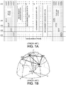
- FIG. 1 illustrates conceptually an FTM positioning procedure.
- the FTM positioning procedure starts with a setup phase, followed with a measurement phase, and ended with a tear down phase.
- the initiating station STA sends an FTM request or FTM requests to each of the responding APs, AP1-AP4, and wait for acknowledgments (ACKs) from AP1-AP4.
- ACKs acknowledgments
- the initiating station STA might be required to switch to the operating channel of the responding AP if the station's current channel is different from the operating channels of the AP.
- the FTM request contains FTM related parameters including the start time and the duration of the subsequent FTM frame exchange.
- the STA starts the measurement phase with each AP.
- the STA exchanges FTM frames and obtains measurement results for TOF with each AP and thereby computing its distance to the corresponding AP. Again, channel switching between each measurement session may be needed if the wireless channels of the APs are different.
- the STA is then able to determine its absolute location given the APs' positions. Finally, the STA and the APs go through a tear down phase to end the FTM positioning procedure.
- Figure 1B Prior Art
- Figure 1B illustrates the geometry of AP positions.
- the STA positioning error obtained from processing the timing measurements, is related to the geometry of the AP positions. This is typically describes by a parameter call PDOP (Position of Dilation).
- PDOP Portion of Dilation
- the PDOP is inversely proportional to the volume of tetrahedron formed by unit directional vectors between AP and STA positions. To achieve low positioning error, it is necessary that APs be deployed at strategically selected positions within a coverage area.
- the FTM protocol suffers from a list of drawbacks.
- the station possibly needs to switch to different channels in which the APs operate on.
- the station needs to consume high power due to the long sessions of FTM frame exchange.
- dense AP deployment is required to provide good coverage for supporting FTM positioning.
- FTM traffic load increases when more stations perform positioning.
- the FTM protocol overhead can be substantial if all stations in a dense environment need to perform ranging independently.
- a solution for simplified Indoor Location operation with simplified deployment is sought.
- a method of indoor positioning using Fine Timing Measurement (FTM) protocol with multi-antenna access point (AP) is proposed.
- FTM Fine Timing Measurement
- AP multi-antenna access point
- a wireless local area network an AP has multiple antennas that are strategically located in different physical locations.
- the AP is used to exchange FTM frames with a wireless station for timing measurement of the FTM frames via its multiple antennas independently.
- the timing measurement result e.g., timestamps corresponding to the departure time of transmitting and the arrival time of the receiving FTM frames
- a simplified Indoor Location operation with simplified deployment is achieved.
- a wireless station requests FTM measurement with an access point (AP) using Wi-Fi technology in an indoor wireless local area network.
- the AP exchanges FTM frames with the station via a first antenna and measures a first set of timestamps associated with the first antenna.
- the AP also exchanges FTM frames with the station via a second antenna and measures a second set of timestamps associated with the second antenna.
- the AP then transmits the first and the second set of timestamps to the station.
- AP can exchange FTM frames with the station via only one of its antenna and simultaneously measure the timestamps (of the FTM frame arrival times) from all its antennas.
- an access point transmits an FTM request to a wireless station (STA) using Wi-Fi technology in an indoor wireless local area network.
- the AP exchanges FTM frames with the station via a first antenna and receives a first set of timestamps associated with the first antenna.
- the AP also exchanges FTM frames with the station via a second antenna and receives a second set of timestamps associated with the second antenna.
- the AP determines a location of the station based at least in part on the first and the second set of timestamps.
- AP can request FTM frames with the station via only one of its antenna and simultaneously measure the timestamps (of the FTM frame arrival times) from all its antennas.
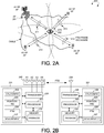
- FIG. 2A illustrates a wireless local area network 200 supporting multi-antenna AP FTM protocol in accordance with one novel aspect.
- Wireless local area network 200 is an indoor network and comprises a multi-antenna access point AP 201 and a wireless non-AP station STA 202.
- AP 201 is a multi-antenna AP comprising at least four antennas A1-A4. The multiple antennas are physical located in separate strategically chosen physical locations, via long extending cables.
- AP 201 has information about all the absolute locations of the multiple antennas.
- AP 201 is used to provide positioning service for STA 202 in an indoor environment via Fine Timing Measurement (FTM) protocol.
- FTM Fine Timing Measurement
- an initiating station exchanges FTM frames with a responding station to measure the time-of-flight (TOF) or the Round Trip Delay (RTD/2) .
- TOF time-of-flight
- RTD/2 Round Trip Delay
- the initiating station then computes its range to the responding station. Based on the location of the responding station, the initiating station is then able to determine its own location.
- FTM positioning requires the initiating station to exchange FTM frames with multiple responding APs for TOF measurements in order to determine its absolute location. For 3D positioning, the station needs to exchange FTM frames with four APs in order to determine its absolute location.
- AP 201 has multiple antennas, which are located in strategically chosen locations and can be used to exchange FTM frames with STA 202 independently.
- STA 202 measures the TOF to A1 of AP 201 via FTM frame exchange 211, the TOF to A2 of AP 201 via FTM frame exchange 212, the TOF to A3 of AP 201 via FTM frame exchange 213, and the TOF to A4 of AP 201 via FTM frame exchange 214.
- STA 202 is then able to compute its ranges to the different antennas A1-A4 of the same AP 201 and thereby determining its absolute location.
- the proposed FTM positioning method involves simplified operation and simplified deployment.
- each antenna can be assigned a separate BSSID (Basic Service Set ID) such that it appears to be an independent AP.
- BSSID Basic Service Set ID
- the IEEE 802.11REVmc does not preclude this kind of usage because the AP only needs to provide an explicit list of BSSID values that share the same antenna connector. Therefore, the current IEEE specification allows the proposed multiple antenna operation when each antenna is treated as an independent BSSID.
- FIG. 2B is a simplified block diagram of an initiating wireless station 221 and a responding wireless station 231 in accordance with one novel aspect.
- the initiating device is referred to as an initiator, and the responding device is referred to as a responder. Both devices can be an AP station or a non-AP station.
- Initiating device 221 comprises memory 222, a processor 223, a control and configuration module 224, a positioning module 225, an FTM module 226, and a measurement module 227, and a transceiver 228 coupled to antenna 230.
- responding device 231 comprises memory 232, a processor 233, a control and configuration module 234, a positioning module 235, an FTM module 236, a measurement module 237, and a transceiver 238 coupled to antenna 240.
- responding device 231 is a multi-antenna AP, e.g., antenna 240 comprises multiple antennas A1-A4.
- the transmitting device 221 can be a multi-antenna AP comprising multiple antennas.
- the transceiver converts received baseband signals from the processor to RF signals and sends out to the antenna.
- the processor processes the received baseband signals from the transceiver and invoke different functional modules to perform various features and embodiments supported by the wireless devices.
- the different modules are functional modules that can be implemented and configured in software, firmware, hardware, or any combination thereof.
- the function modules when executed by processors 223 and 233 (via program instructions 229 and 239 contained in memory 222 and 232), interwork with each other to allow the wireless devices to perform enhanced channel access.
- the measurement module performs FTM measurement frame timing measurements
- the FTM module establishes the FTM procedure involving setup phase, measurement phase, and tear down phase
- the positioning module determines the absolute location of the wireless device based on the FTM measurement result
- the control and configuration module configures FTM related parameters and controls the FTM procedure.
- the FTM related timing measurements are the departure time of a specific reference point at the transmit frame and the arrival of time of a specific reference point at the receive frame.
- the hardware delay within the signal path in the transceiver and cable should be calibrated and removed to yield the accurate timestamp measurements at the antenna.
- FIG 3 illustrates a baseline FTM positioning procedure between an initiating station STA and a multi-antenna AP.
- the FTM positioning procedure starts with a setup phase, followed with a measurement phase, and ended with a tear down phase.
- the STA sends an FTM request to a multi-antenna responding AP, and wait for an acknowledgment (ACK) from the AP.
- the FTM request contains FTM related parameters including the start time and duration of the subsequent FTM frame exchange. Note that if each antenna of the multi-antenna AP employs a separate BSSID, then it is treated as a separate AP from the STA perspective.
- the STA would need to send four FTM requests to each antenna and receive four ACKs from each antenna in order to properly setup the FTM procedure.
- the STA only needs to send one FTM request to the AP and receive one ACK from the AP to setup the FTM procedure.
- the STA starts the measurement phase with the AP.
- the STA exchanges FTM frames and obtains measurement results for TOF with a corresponding antenna of the AP and thereby computing its distance to the corresponding antenna of the AP.
- the STA is then able to determine its absolute location given the AP/antenna positions.
- the STA and the AP go through a tear down phase to end the FTM positioning procedure. Because the FTM frame exchanges are performed with the same AP, channel switching between each measurement sessions are not needed.
- FIG 4A is an example of an FTM request frame 410.
- FTM request frame 410 comprises a 1-octet Category field, a 1-octet Public Action field, a 1-octet Trigger field, an optional LCI measurement request, an optional Location Civic Measurement Request field, and an optional FTM Parameter field.
- the category field is set to the value for Public.
- the Public Action filed is set to indicate a FTM request frame.
- the Trigger field set to "1" indicates that the initiating STA requests that the responding STA start or continue sending FTM measurement frames.
- the Trigger field set to "0" indicates that the initiating STA requests that the responding STA stop sending FTM measurement frames.
- the LCI Measurement Request field if present, contains a Measurement Request element with Measurement Type equal to LCI request, which indicates a request for a Measurement Report element with Measurement Type equal to LCI.
- the Location Chrysler Measurement Request field if present, contains a Measurement Request element with Measurement Type equal to Location® Request, which indicates a request for Measurement Report element with Measurement Type equal to Location® report.
- the FTM Parameter field is present in the initial FTM Request frame, and is not present in subsequent FTM Request trigger frames. If present, it contains a FTM parameter element.
- FIG. 4B is an example of an FTM action frame 420.
- FTM action frame 420 comprises a 1-octet Category field, a 1-octet Public Action field, a 1-octet Dialog Token field, a 1-octet Follow Up Dialog Token field, a 6-octet TOD field, a 6-octet TOA field, a 2-octet TOD Error field, a 2-octet TOA Error field, an optional LCI Report field, an optional Location Civic Report field, and an optional FTM Parameter field.
- the category field is set to the value for Public.
- the Public Action filed is set to indicate a FTM frame.
- the Dialog Token field is a nonzero value chosen by the responding STA to identify the FTM frame as the first of a pair, with the second or follow-up FTM frame to be sent later.
- the Dialog Token field is set to "0" to indicate that the FTM frame will not be followed by a subsequent follow-up FTM frame.
- the Follow Up Dialog Token field is the nonzero value of the Dialog Token field of the last transmitted FTM frame to indicate that it is the follow up FTM frame and that the TOD, TOA, Max TOD Error and Max TOA Error fields contain the values of the timestamps captured with the first FTM frame of the pair.
- the Follow Up Dialog Token field is set to "0" to indicate that the FTM frame is not a follow up to a last transmitted FTM.
- the TOD, TOA, Max TOD Error, and Max TOA Error fields are expressed in units of 0.1 ns.
- the TOD field contains a timestamp that represents the time, with respect to a time base, at which the start of the preamble of the last transmitted FTM frame appeared at the transmit antenna connector.
- the TOA field contains a timestamp that represents the time, with respect to a time base, at which the start of the preamble of the ACK frame to the last transmitted FTM frame arrived at the receive antenna connector.
- the Max TOD Error field contains an upper bound for the error in the value specified in the TOD field.
- the Max TOA Error field contains an upper bound for the error in the value specified in the TOA field.
- the LCI Report field is optionally present. If present, it contains a Measurement Report element with Measurement Type equal to LCI report.
- the Location Civic Report field is optionally present. If present, it contains a Measurement Report element with Measurement Type equal to Location Civic report.
- the Fine Timing Measurement Parameter field is present in the initial Fine Timing Measurement Frame, and is not present in subsequent Fine Timing Measurement frames. If present, it contains a Fine Timing Measurement Parameter element.
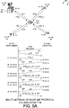
- FIG. 5A illustrates an STA initiated baseline FTM protocol with multi-antenna AP in a wireless location area network 500.
- Wireless local area network 500 is an indoor network and comprises a multi-antenna access point AP 501 and a wireless non-AP station STA 502.
- AP 501 is a multi-antenna AP comprising at least four antennas A1-A4. The multiple antennas are strategically located in separate physical locations, via long extending cables (not shown).
- STA 502 is an initiating device that initiates an FTM positioning procedure
- AP 501 is a responding device that responds to the FTM positioning procedure.
- step 511 STA 502 initiates an FTM procedure by sending an FTM request to AP 501 to set up the joint operation for antenna A1, A2, A3, A4.
- step 512 AP 501 accepts the FTM request and sends an ACK frame back to STA 502.
- FTM_2 payload also includes the timestamps t1_A1 and t4_A1 of the first measurement session.
- STA 502 receives the timestamps of the previous measurement session in a subsequent FTM payload.
- STA 502 computes the time-of-flight (TOF) or Round Trip Delay (RTD/2) and its corresponding range/distance to each antenna of AP 501.
- TOF time-of-flight
- RTD/2 Round Trip Delay
- STA 502 In three-dimensional (3D) positioning, if STA 502 knows the absolute locations of the AP/antennas, and its relative range to each of the four antennas, then STA 502 is able to determine its own location.
- FIG. 5B illustrates another embodiment of an STA initiated baseline FTM protocol with a multi-antenna AP.
- the AP designates different SSIDs for operations via different antennas.
- An independent FTM request and FTM measurement procedure is initiated by the station using an SSID is used for each antenna. Note that this operation complies with the current IEEE 802.11REVmc protocol.
- the STA sends an FTM request using SSID_A1 for antenna A1 of the AP.
- the STA receives an ACK from the AP.
- the payload of FTM_2 includes timestamps t1_A1 and t4_A1.
- step 541 the STA sends an FTM request using SSID_A2 for antenna A2 of the AP.
- step 542 the STA receives an ACK from the AP.
- the payload of FTM_2 includes timestamps t1_A2 and t4_A2.
- the same FTM frame exchange may happen between the STA and the AP via its third and fourth antennas. Similar to Figure 5A , the station is then able to determine its location based on the FTM ranging results with the four antennas of the AP.
- FIG. 5C illustrates an AP initiated baseline FTM protocol with multi-antenna AP in a wireless location area network 550.
- Wireless local area network 550 is an indoor network and comprises a multi-antenna access point AP 551 and a wireless non-AP station STA 552.
- AP 551 is a multi-antenna AP comprising at least four antennas A1-A4. The multiple antennas are strategically located in separate physical locations, via long extending cables (not shown).
- AP 551 is an initiating device that initiates an FTM positioning procedure
- STA 552 is a responding device that responds to the FTM positioning procedure.
- a wireless station is normally the initiator due to privacy reason.
- an AP can track the location of certain stations. For example, in a warehouse environment, the AP may want to track the exact location of each station for efficient management of processing shipping and handling.
- AP 551 initiates an FTM procedure by sending an FTM request to STA 552 to set up the joint FTM operation for all four antennas.
- STA 552 accepts the FTM request and sends an ACK frame back to AP 551.
- AP 551 receives the timestamps of the previous measurement session in a subsequent FTM payload.
- AP 551 computes the time-of-flight (TOF) or Round Trip Delay (RTD/2) and its corresponding range/distance from each antenna to STA 552.
- TOF time-of-flight
- RTD Round Trip Delay
- the AP can designate different SSIDs for operations via different antennas. AP can initiate an independent FTM request and FTM measurement procedure using a SSID for each antenna.
- AP 551 In three-dimensional (3D) positioning, based on the relative range/distance from each of the four antennas to STA 552, AP 551 is able to determine the absolute location of STA 552. Finally, in step 572, AP 551 may optionally sends the STA location to STA 551.
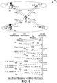
- FIG. 6 illustrates a hybrid FTM protocol with multi-antenna AP in a wireless location area network 600.
- Wireless local area network 600 is an indoor network and comprises two multi-antenna access points AP1 601 and AP2 602 and a wireless non-AP station STA 603.
- AP1 AP2 are multi-antenna APs comprising at least two antennas A1-A2.
- the multiple antennas are strategically located in separate physical locations, via long extending cables (not shown) .
- STA 603 is an initiating device that initiates an FTM positioning procedure, while AP1 and AP2 are responding devices that respond to the FTM positioning procedure.
- step 611 STA 603 sends FTM requests to both AP1 and AP2.
- step 612 STA 603 receives ACKs from AP1 and AP2. Note that channel switching may be required if AP1 and AP2 operate in different channels.
- FTM_2 payload also includes the timestamps t1_A1_1 and t4_A1_1 of the first measurement session.
- AP1 transmits a third FTM frame FTM_3 to STA 603.
- FTM_3 payload includes the timestamps t1_A1_1 and t4_A2_1 of the second measurement session.
- the FTM operation with two APs are still simpler than the traditional FTM operation with four APs.
- STA 603 computes the time-of-flight (TOF) or Round Trip Delay (RTD/2) and its corresponding range/distance to each antenna of both AP1 and AP2.
- TOF time-of-flight
- RTD Round Trip Delay
- STA 603 In three-dimensional (3D) positioning, if STA 603 knows the absolute location of the APs/antennas, and its relative range/distance to each antenna, then STA 603 is able to determine its own location.
- FIG. 7 illustrates a simplified implementation of an STA initiated FTM protocol with multi-antenna AP in a wireless local area network 700.
- Wireless local area network 700 is an indoor network and comprises a multi-antenna access point AP 701 and a wireless non-AP station STA 702.
- AP 701 is a multi-antenna AP comprising at least four antennas A1-A4 .
- the multiple antennas are strategically located in separate physical locations, via long extending cables (not shown).
- three antennas A2-A4 only receives radio frames passively.
- STA 702 is an initiating device that initiates an FTM positioning procedure
- AP 701 is a responding device that responds to the FTM positioning procedure.
- step 711 STA 702 initiates an FTM procedure by sending an FTM request to AP 701.
- step 712 AP 701 accepts the FTM request and sends an ACK frame back to STA 702.
- AP 701 transmits a second FTM frame FTM_2 to STA 702.
- the FTM_2 payload includes the previous timestamps of t1_A1, t4_A1, t4_A2, t4_A3, and t4_A4. Because AP 701 can simultaneously measure time t4 from all of its four antennas, four-time reduction of FTM measurement frame exchange can be achieved in this simplified implementation.
- STA 702 In three-dimensional (3D) positioning, if STA 702 knows the absolute locations of the AP/antennas, and its relative range to each of the four antennas, then STA 702 is able to determine its own location.
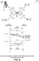
- FIG 8 illustrates a simplified implementation of an AP initiated FTM protocol with multi-antenna AP in a wireless local area network 800.
- Wireless local area network 800 is an indoor network and comprises a multi-antenna access point AP 801 and a wireless non-AP station STA 802.
- AP 801 is a multi-antenna AP comprising at least four antennas A1-A4. The multiple antennas are strategically located in separate physical locations, via long extending cables (not shown).
- AP 801 is an initiating device that initiates an FTM positioning procedure to track STA location, while STA 802 is a responding device that responds to the FTM positioning procedure.
- AP 801 initiates an FTM procedure by sending an FTM request to STA 802.
- STA 802 accepts the FTM request and sends an ACK frame back to AP 801.
- AP 801 receives FTM_1 via antenna A1 at time instance t2_A1, via antenna A2 at time instance t2_A2, via antenna A3 at time instance t2_A3, and via antenna A4 at time instance t2_A4.
- AP 801 transmits a corresponding ACK frame to STA 802 at time instance t3_A1 via antennas A1.
- STA 802 receives the ACK frame at time instance t4 from antenna A1.
- STA 802 transmits a second FTM frame FTM_2 to AP 801.
- the FTM_2 payload includes the previous timestamps of t1_A1 and t4_A1.
- AP 801 computes the time-of-flight (TOF) or Round Trip Delay (RTD/2) and its corresponding range/distance from each antenna to STA 802.
- TOF time-of-flight
- RTD Round Trip Delay
- AP 801 In three-dimensional (3D) positioning, based on the relative range/distance from each of the four antennas to STA 802, AP 801 is able to determine the absolute location of STA 802. Finally, in step 816, AP 801 may optionally sends the STA location to STA 802.
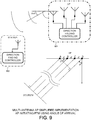
- FIG. 9 illustrates multi-antenna AP FTM protocol using Angle of Arrival (AoA).
- AoA measurement is a method for determining the direction of propagation of a radio signal on an antenna array. AoA determines the direction by measuring the Time Difference of Arrival (TDOA) at individual antenna elements of the array, and from these delays, the AoA can be calculated.
- TDOA Time Difference of Arrival
- AP 901 has an antenna array and a direction-finding controller
- STA 902 has a single antenna and a direction-fining controller.
- the timing delay from the station to the AP can be measured based on distance (d), and the AoA ( ⁇ ) can be calculated.
- the knowledge of AoA can be combined with the knowledge of the distance between the AP and the station so that the AP can determine the location of the STA.
- FIG 10 illustrates one embodiment of reducing airtime for a simplified implementation of FTM protocol with multi-antenna AP in a wireless local area network 1000.
- Wireless local area network 1000 is an indoor network and comprises a multi-antenna access point AP 1001 and a wireless non-AP station STA 1002.
- AP 1001 is a multi-antenna AP comprising at least four antennas A1-A4. The multiple antennas are strategically located in separate physical locations, via long extending cables (not shown) .
- three antennas A2-A4 only receives radio frames passively.
- STA 1002 is an initiating device that initiates an FTM positioning procedure
- AP 1001 is a responding device that responds to the FTM positioning procedure.
- STA 1002 initiates an FTM procedure by sending an FTM request to AP 1001.
- AP 1001 constantly measures the timestamps (t_A1, t_A2, t_A3, and tA4) of receiving the FTM request via each of the antennas A1-A4, respectively.
- AP 1001 sends the timestamps to STA 1002 so that it can calculate its location.
- AP 1001 calculates the STA position using triangulation and send the STA position to STA 1002 in step 1012.
- AP 1001 initiates the FTM procedure by sending an FTM trigger to STA 1002.
- STA 1002 sends an FTM request to AP 1001 in step 1022.
- AP 1001 constantly measures the timestamps (t_A1, t_A2, t_A3, and tA4) of receiving the FTM request via each of the antennas A1-A4, respectively.
- AP 1001 sends the timestamps to STA 1002 so that it can calculate its location.
- AP 1001 calculates the STA position using triangulation and send the STA position to STA 1002 in step 1023.
- airtime is further reduced by constantly measuring via different antennas and eliminating FTM measurement frame exchanges.
- FIG 11 is a flow chart of a method of a baseline FTM protocol with multi-antenna AP in accordance with one novel aspect.
- an access point receives an FTM request from a wireless station (STA) using Wi-Fi technology in an indoor wireless local area network.
- the AP exchanges FTM frames with the station via a first antenna and measures a first set of timestamps associated with the first antenna.
- the AP exchanges FTM frames with the station via a second antenna and measures a second set of timestamps associated with the second antenna.
- the AP transmits the first and the second set of timestamps to the station.
- each antenna is physical separated by cables, and each antenna is associated with an independent Basic Service Set ID (BBSID).
- BBSID Basic Service Set ID
- the AP has at least four antennas for determining an absolute location of the station.
- FIG. 12 is a flow chart of a method of a simplified FTM protocol with multi-antenna AP in accordance with one novel aspect.
- an access point transmits an FTM request to a wireless station (STA) using Wi-Fi technology in an indoor wireless local area network.
- the AP exchanges FTM frames with the station via a first antenna and receives a first set of timestamps associated with the first antenna.
- the AP exchanges FTM frames with the station via a second antenna and receives a second set of timestamps associated with the second antenna.
- the AP determines a location of the station based at least in part on the first and the second set of timestamps.
- each antenna is physical separated by cables, and each antenna is associated with an independent Basic Service Set ID (BBSID).
- BBSID Basic Service Set ID
- the AP has at least four antennas for determining an absolute location of the station.
Landscapes
- Engineering & Computer Science (AREA)
- Radar, Positioning & Navigation (AREA)
- Remote Sensing (AREA)
- Physics & Mathematics (AREA)
- General Physics & Mathematics (AREA)
- Computer Networks & Wireless Communication (AREA)
- Signal Processing (AREA)
- Mobile Radio Communication Systems (AREA)
- Position Fixing By Use Of Radio Waves (AREA)
Claims (15)
- Verfahren, umfassend:(a) Empfangen einer oder mehrerer Fein-Zeit-Messungs-, FTM-, Anforderungen von einer Funkstation durch einen Zugangspunkt, AP, in einem lokalen Funknetzwerk für Innenbereiche, wobei der AP mehrere Antennen aufweist, die strategisch an verschiedenen Standorten über langgestreckte Kabel angeordnet sind (1101);(b) Austauschen von FTM-Rahmen mit der Station über eine erste Antenne und Messen einer ersten Gruppe von Zeitmarken, die mit der ersten Antenne verknüpft sind, wobei die erste Gruppe von Zeitmarken an die Station gesendet wird (1102); und(c) Austauschen von FTM-Rahmen mit der Station über eine zweite Antenne und Messen einer zweiten Gruppe von Zeitmarken, die mit der zweiten Antenne verknüpft sind, wobei die zweite Gruppe von Zeitmarken an die Station gesendet wird (1103).
- Verfahren gemäß Anspruch 1, wobei jede Antenne mit einer unabhängigen Basisdienstsatz-ID, BBSID, verknüpft ist.
- Verfahren gemäß Anspruch 2, wobei (b) ein Senden eines ersten FTM-Rahmens an die Station und als Reaktion ein Empfangen eines ersten ACK-Rahmens über die erste Antenne umfasst, und wobei (c) ein Senden eines zweiten FTM-Rahmens an die Station und als Reaktion ein Empfangen eines zweiten ACK-Rahmens über die zweite Antenne umfasst.
- Verfahren gemäß Anspruch 3, wobei die erste Gruppe von Zeitmarken eine Sendezeitmarke des ersten FTM-Rahmens und eine Empfangszeitmarke des ersten ACK-Rahmens aufweist; und/oder wobei die zweite Gruppe von Zeitmarken eine Sendezeitmarke des zweiten FTM-Rahmens und eine Empfangszeitmarke des zweiten ACK-Rahmens aufweist.
- Verfahren gemäß Anspruch 1, wobei (b) ein Senden eines ersten FTM-Rahmens an die Station und als Reaktion ein Empfangen eines ersten ACK-Rahmens über die erste Antenne umfasst, und wobei (c) ein Empfangen des ersten ACK-Rahmens als Reaktion auf den ersten FTM-Rahmen von der Station über die zweite Antenne umfasst.
- Verfahren gemäß Anspruch 5, wobei die erste Gruppe von Zeitmarken eine Sendezeitmarke des ersten FTM-Rahmens und eine Empfangszeitmarke des ersten ACK-Rahmens, der durch die erste Antenne empfangen wird, aufweist, und wobei die zweite Gruppe von Zeitmarken eine Empfangszeitmarke des ersten ACK-Rahmens, der durch die zweite Antenne empfangen wird, aufweist.
- Verfahren gemäß Anspruch 5, weiter umfassend:Empfangen des ersten ACK-Rahmens als Reaktion auf den ersten FTM-Rahmen von der Station über eine dritte Antenne und Messen einer Empfangszeitmarke des ersten ACK-Rahmens, der durch die dritte Antenne empfangen wird; undEmpfangen des ersten ACK-Rahmens als Reaktion auf den ersten FTM-Rahmen von der Station über eine vierte Antenne und Messen einer Empfangszeitmarke des ersten ACK-Rahmens, der durch die vierte Antenne empfangen wird;wobei vorzugsweise der AP die gemessenen Zeitmarken an die Station sendet, sodass die Station in der Lage ist, einen absoluten Standort zu bestimmen.
- Verfahren gemäß Anspruch 1, wobei der AP mindestens vier Antennen aufweist, wobei der AP vier Empfangszeitmarken über die vier Antennen als Reaktion auf einen FTM-Rahmen, der von der Station gesendet wird, misst.
- Verfahren, umfassend:(a) Senden einer oder mehrerer Fein-Zeit-Messungs-, FTM-, Anforderungen von einem Zugangspunkt, AP, an eine Funkstation in einem lokalen Funknetzwerk für Innenbereiche, wobei der AP mehrere Antennen aufweist, die strategisch an verschiedenen Standorten über langgestreckte Kabel angeordnet sind (1201);(b) Austauschen von FTM-Rahmen mit der Station über eine erste Antenne und Empfangen einer ersten Gruppe von Zeitmarken, die mit der ersten Antenne verknüpft sind (1202);(c) Austauschen von FTM-Rahmen mit der Station über eine zweite Antenne und Empfangen einer zweiten Gruppe von Zeitmarken, die mit der zweiten Antenne verknüpft sind (1203); und(d) Bestimmen eines Standorts der Station mindestens teilweise basierend auf der ersten und der zweiten Gruppe von Zeitmarken (1204).
- Verfahren gemäß Anspruch 9, wobei jede Antenne mit einer unabhängigen Basisdienstsatz-ID, BBSID, verknüpft ist; und/oder wobei der AP einen Empfangswinkel der Station basierend auf dem FTM-Rahmenaustausch misst und dadurch den Standort der Station bestimmt.
- Verfahren gemäß Anspruch 9, wobei (b) ein Empfangen eines ersten FTM-Rahmens von der Station und als Reaktion ein Senden eines ersten ACK-Rahmens an die Station über die erste Antenne umfasst, und wobei (c) ein Empfangen eines zweiten FTM-Rahmens von der Station und als Reaktion ein Senden eines zweiten ACK-Rahmens an die Station über die zweite Antenne umfasst.
- Verfahren gemäß Anspruch 11, wobei die erste Gruppe von Zeitmarken eine Sendezeitmarke des ersten FTM-Rahmens und eine Empfangszeitmarke des ersten ACK-Rahmens aufweist; und/oder wobei die zweite Gruppe von Zeitmarken eine Sendezeitmarke des zweiten FTM-Rahmens und eine Empfangszeitmarke des zweiten ACK-Rahmens aufweist.
- Verfahren gemäß Anspruch 9, wobei (b) ein Empfangen und Messen eines ersten FTM-Rahmens über die erste Antenne und als Reaktion ein Senden eines ersten ACK-Rahmens an die Station über die erste Antenne umfasst, wobei (c) ein Empfangen und Messen des ersten FTM-Rahmens über die zweite Antenne umfasst.
- Verfahren gemäß Anspruch 13, wobei die erste und die zweite Gruppe von Zeitmarken eine Sendezeitmarke des ersten FTM-Rahmens und eine Empfangszeitmarke des ersten ACK-Rahmens aufweisen.
- Verfahren gemäß Anspruch 13, weiter umfassend:Empfangen des ersten FTM-Rahmens über eine dritte Antenne und Messen einer Empfangszeitmarke des ersten FTM-Rahmens über die dritte Antenne; undEmpfangen des ersten FTM-Rahmens über eine vierte Antenne und Messen einer Empfangszeitmarke des ersten FTM-Rahmens über die vierte Antenne;wobei vorzugsweise der AP den Standort der Station basierend auf den empfangenen und gemessenen Zeitmarken bestimmt.
Applications Claiming Priority (2)
| Application Number | Priority Date | Filing Date | Title |
|---|---|---|---|
| US201361888124P | 2013-10-08 | 2013-10-08 | |
| PCT/US2014/059581 WO2015054324A2 (en) | 2013-10-08 | 2014-10-08 | Multiple antenna ap positioning in wireless local area networks |
Publications (3)
| Publication Number | Publication Date |
|---|---|
| EP3039925A2 EP3039925A2 (de) | 2016-07-06 |
| EP3039925A4 EP3039925A4 (de) | 2017-05-31 |
| EP3039925B1 true EP3039925B1 (de) | 2020-03-18 |
Family
ID=52777370
Family Applications (1)
| Application Number | Title | Priority Date | Filing Date |
|---|---|---|---|
| EP14851890.5A Active EP3039925B1 (de) | 2013-10-08 | 2014-10-08 | Mehrantennen-ap-positionierung in drahtlosen lokalen netzwerken |
Country Status (3)
| Country | Link |
|---|---|
| US (1) | US10104493B2 (de) |
| EP (1) | EP3039925B1 (de) |
| WO (1) | WO2015054324A2 (de) |
Families Citing this family (29)
| Publication number | Priority date | Publication date | Assignee | Title |
|---|---|---|---|---|
| US9332523B2 (en) * | 2013-05-10 | 2016-05-03 | Qualcomm, Incorporated | Systems and methods of offloaded positioning for determining location of WLAN nodes |
| US9854468B2 (en) | 2014-03-05 | 2017-12-26 | Marvell World Trade Ltd. | Method and apparatus for estimating distance between network devices in a wireless network |
| US9220081B2 (en) * | 2014-03-05 | 2015-12-22 | Intel Corporation | Access point location discovery in unmanaged networks |
| US20150264530A1 (en) * | 2014-03-12 | 2015-09-17 | Gaby Prechner | Access point initiated time-of-flight positioning |
| US10716024B2 (en) * | 2014-09-12 | 2020-07-14 | Qualcomm Incorporated | Methods and systems for ranging protocol |
| US10158547B2 (en) | 2014-10-27 | 2018-12-18 | Qualcomm Incorporated | Method for a procedure for determining distance or angle between electronic devices connected wirelessly |
| US9907042B2 (en) * | 2015-06-15 | 2018-02-27 | Intel IP Corporation | Apparatus, system and method of determining a time synchronization function (TSF) based on fine time measurement (FTM) messages |
| US9781560B2 (en) * | 2015-07-02 | 2017-10-03 | Qualcomm Incorporated | Ranging over multiple antennas |
| US10009430B2 (en) * | 2015-08-27 | 2018-06-26 | Intel IP Corporation | Apparatus, system and method of fine timing measurement (FTM) |
| US20170171766A1 (en) * | 2015-12-13 | 2017-06-15 | Yuval Amizur | Fine timing measurement |
| CN106936559B (zh) | 2015-12-29 | 2020-01-31 | 华为技术有限公司 | 一种精细时间测量ftm方法和通信设备 |
| KR102469281B1 (ko) * | 2016-05-13 | 2022-11-22 | 삼성전자주식회사 | 안테나를 포함하는 전자 장치 |
| EP3510706B1 (de) * | 2016-09-09 | 2025-11-12 | Sony Group Corporation | Kommunikationsvorrichtungen und -verfahren für rf-basierte kommunikation und positionsbestimmung |
| EP3635431A1 (de) * | 2017-05-04 | 2020-04-15 | Eaton Intelligent Power Limited | Mehrdimensionale ortung eines objekts unter verwendung mehrerer antennen |
| US10725145B2 (en) | 2017-05-04 | 2020-07-28 | Signify Holding B.V. | Multi-dimensional location of an object using multiple electrical devices |
| KR102012423B1 (ko) * | 2017-09-20 | 2019-08-20 | 성균관대학교산학협력단 | 무선 전력 전송 에너지 하베스팅 시스템에서 무선 랜과 동일한 주파수 대역에서 동작하는 에너지 신호 전송 장치에서의 무선 전력 전송 방법 및 이를 수행하는 에너지 신호 전송 장치 |
| WO2019185205A2 (en) | 2018-03-28 | 2019-10-03 | Eaton Intelligent Power Limited | Sensors with multiple antennae used for multi-dimensional location of an object |
| US11381275B2 (en) * | 2018-03-31 | 2022-07-05 | Qualcomm Incorporated | Ranging protocol improvements to support antenna switching |
| US20210029665A1 (en) | 2018-04-19 | 2021-01-28 | Nec Corporation | Terminal, radio communication system, and communication method |
| CN109874103A (zh) * | 2019-04-23 | 2019-06-11 | 上海寰创通信科技股份有限公司 | 一种wifi精确定位设备及方法 |
| US11095319B2 (en) * | 2019-07-26 | 2021-08-17 | Apple Inc. | Wireless ranging using physical and virtual responders |
| US11265842B2 (en) | 2020-03-09 | 2022-03-01 | Cisco Technology, Inc. | Wireless station ranging using channel state |
| US11395252B2 (en) * | 2020-07-23 | 2022-07-19 | Skyhook Wireless, Inc. | Crowd sourced RTT-based positioning |
| CN115061084B (zh) * | 2021-03-09 | 2025-06-24 | 华为技术有限公司 | 时间测量方法及装置 |
| US11856435B2 (en) | 2021-03-31 | 2023-12-26 | Hewlett Packard Enterprise Development Lp | Handling fine timing measurement requests |
| US12402120B2 (en) | 2022-03-01 | 2025-08-26 | Cisco Technology, Inc. | Ceiling-controlled communication scheduling in an overhead mesh of access points |
| CN115174023B (zh) * | 2022-06-27 | 2024-01-05 | 杭州海康威视数字技术股份有限公司 | 一种多天线基站测距系统、方法及装置 |
| US12411202B2 (en) | 2022-12-14 | 2025-09-09 | Cisco Technology, Inc. | Estimating position from reference signals received by coordinating access points |
| US12439370B2 (en) | 2022-12-19 | 2025-10-07 | Cisco Technology, Inc. | Automated position estimation based on coordinating access points |
Family Cites Families (15)
| Publication number | Priority date | Publication date | Assignee | Title |
|---|---|---|---|---|
| US7411921B2 (en) | 1999-10-21 | 2008-08-12 | Rf Technologies, Inc. | Method and apparatus for integrating wireless communication and asset location |
| US6847330B2 (en) * | 2003-06-23 | 2005-01-25 | Netgear Inc. | Detachable 802.11a antenna detection |
| US6909399B1 (en) | 2003-12-31 | 2005-06-21 | Symbol Technologies, Inc. | Location system with calibration monitoring |
| US7574732B2 (en) | 2004-09-29 | 2009-08-11 | Symbol Technologies Inc | Object location based security using RFID |
| EP1970725A1 (de) | 2007-03-15 | 2008-09-17 | Telefonaktiebolaget LM Ericsson (publ) | Positioniervorrichtung und Betriebsverfahren dafür |
| US8774084B2 (en) | 2008-08-22 | 2014-07-08 | Qualcomm Incorporated | Base station synchronization |
| US9057606B2 (en) | 2009-09-10 | 2015-06-16 | Nextnav, Llc | Wide area positioning system |
| US8233457B1 (en) * | 2009-09-03 | 2012-07-31 | Qualcomm Atheros, Inc. | Synchronization-free station locator in wireless network |
| CN103097905A (zh) * | 2010-06-01 | 2013-05-08 | 艾德普顿斯公司 | 用于室内定位的系统和方法 |
| US8878721B2 (en) | 2011-06-02 | 2014-11-04 | Qualcomm Incorporated | Hybrid positioning using timing reference information |
| US8897813B2 (en) | 2012-02-03 | 2014-11-25 | Andrew Llc | LTE user equipment positioning system and method |
| US20140073352A1 (en) * | 2012-09-11 | 2014-03-13 | Qualcomm Incorporated | Method for precise location determination |
| US10039073B2 (en) * | 2013-01-03 | 2018-07-31 | Qualcomm Incorporated | Method for determining location of wireless devices |
| US9823330B2 (en) * | 2013-05-03 | 2017-11-21 | Cisco Technology, Inc. | Angle of arrival location sensing with antenna array |
| US9226260B2 (en) * | 2013-05-10 | 2015-12-29 | Intel Corporation | Initiator-conditioned fine timing measurement service request |
-
2014
- 2014-10-07 US US14/508,979 patent/US10104493B2/en active Active
- 2014-10-08 EP EP14851890.5A patent/EP3039925B1/de active Active
- 2014-10-08 WO PCT/US2014/059581 patent/WO2015054324A2/en not_active Ceased
Non-Patent Citations (1)
| Title |
|---|
| None * |
Also Published As
| Publication number | Publication date |
|---|---|
| WO2015054324A2 (en) | 2015-04-16 |
| US20150099538A1 (en) | 2015-04-09 |
| WO2015054324A3 (en) | 2015-06-25 |
| EP3039925A4 (de) | 2017-05-31 |
| US10104493B2 (en) | 2018-10-16 |
| EP3039925A2 (de) | 2016-07-06 |
Similar Documents
| Publication | Publication Date | Title |
|---|---|---|
| US10104493B2 (en) | Multiple antenna AP positioning in wireless local area networks | |
| EP3039826B1 (de) | Entfernungsmessung und positionierung in wlans unter verwendung von zeitstempeln eines benachbarten zugangspunkts und einer schnüffelnden station | |
| EP3146774B1 (de) | Feine zeitmessungspositionierung und verbesserungen in drahtlosen lokalen netzwerken | |
| US10624055B2 (en) | Method for determining location of wireless devices | |
| CN111565414B (zh) | 一种用于定位的波束信息获取方法及装置 | |
| US9277369B2 (en) | Method for determining location of wireless devices | |
| EP3844524B1 (de) | Standortinformationsbestimmung basierend auf zeitmessungen in drahtlosen netzwerken | |
| EP3067712B1 (de) | Positionsschätzungsvorrichtung und verfahren für ein drahtloskommunikationssystem | |
| US9288625B2 (en) | Method for determining location of wireless devices based on information within messages received from other network devices | |
| US9066202B2 (en) | Positioning using observer-based time-of-arrival measurements | |
| US20240215054A1 (en) | Communication system and user device | |
| US20220271818A1 (en) | Non-Line-of-Sight Path Detection for User Equipment Positioning in Wireless Networks | |
| US9775007B2 (en) | Group based location service in wireless local area networks |
Legal Events
| Date | Code | Title | Description |
|---|---|---|---|
| PUAI | Public reference made under article 153(3) epc to a published international application that has entered the european phase |
Free format text: ORIGINAL CODE: 0009012 |
|
| 17P | Request for examination filed |
Effective date: 20160330 |
|
| AK | Designated contracting states |
Kind code of ref document: A2 Designated state(s): AL AT BE BG CH CY CZ DE DK EE ES FI FR GB GR HR HU IE IS IT LI LT LU LV MC MK MT NL NO PL PT RO RS SE SI SK SM TR |
|
| AX | Request for extension of the european patent |
Extension state: BA ME |
|
| DAX | Request for extension of the european patent (deleted) | ||
| REG | Reference to a national code |
Ref country code: DE Ref legal event code: R079 Ref document number: 602014062654 Country of ref document: DE Free format text: PREVIOUS MAIN CLASS: H04W0064000000 Ipc: G01S0013740000 |
|
| A4 | Supplementary search report drawn up and despatched |
Effective date: 20170503 |
|
| RIC1 | Information provided on ipc code assigned before grant |
Ipc: H04W 64/00 20090101ALI20170425BHEP Ipc: G01S 13/74 20060101AFI20170425BHEP Ipc: G01S 5/02 20100101ALI20170425BHEP |
|
| GRAP | Despatch of communication of intention to grant a patent |
Free format text: ORIGINAL CODE: EPIDOSNIGR1 |
|
| STAA | Information on the status of an ep patent application or granted ep patent |
Free format text: STATUS: GRANT OF PATENT IS INTENDED |
|
| INTG | Intention to grant announced |
Effective date: 20191104 |
|
| GRAS | Grant fee paid |
Free format text: ORIGINAL CODE: EPIDOSNIGR3 |
|
| GRAA | (expected) grant |
Free format text: ORIGINAL CODE: 0009210 |
|
| STAA | Information on the status of an ep patent application or granted ep patent |
Free format text: STATUS: THE PATENT HAS BEEN GRANTED |
|
| AK | Designated contracting states |
Kind code of ref document: B1 Designated state(s): AL AT BE BG CH CY CZ DE DK EE ES FI FR GB GR HR HU IE IS IT LI LT LU LV MC MK MT NL NO PL PT RO RS SE SI SK SM TR |
|
| REG | Reference to a national code |
Ref country code: GB Ref legal event code: FG4D |
|
| REG | Reference to a national code |
Ref country code: DE Ref legal event code: R096 Ref document number: 602014062654 Country of ref document: DE |
|
| REG | Reference to a national code |
Ref country code: AT Ref legal event code: REF Ref document number: 1246551 Country of ref document: AT Kind code of ref document: T Effective date: 20200415 Ref country code: IE Ref legal event code: FG4D |
|
| PG25 | Lapsed in a contracting state [announced via postgrant information from national office to epo] |
Ref country code: RS Free format text: LAPSE BECAUSE OF FAILURE TO SUBMIT A TRANSLATION OF THE DESCRIPTION OR TO PAY THE FEE WITHIN THE PRESCRIBED TIME-LIMIT Effective date: 20200318 Ref country code: FI Free format text: LAPSE BECAUSE OF FAILURE TO SUBMIT A TRANSLATION OF THE DESCRIPTION OR TO PAY THE FEE WITHIN THE PRESCRIBED TIME-LIMIT Effective date: 20200318 Ref country code: NO Free format text: LAPSE BECAUSE OF FAILURE TO SUBMIT A TRANSLATION OF THE DESCRIPTION OR TO PAY THE FEE WITHIN THE PRESCRIBED TIME-LIMIT Effective date: 20200618 |
|
| REG | Reference to a national code |
Ref country code: NL Ref legal event code: MP Effective date: 20200318 |
|
| PG25 | Lapsed in a contracting state [announced via postgrant information from national office to epo] |
Ref country code: BG Free format text: LAPSE BECAUSE OF FAILURE TO SUBMIT A TRANSLATION OF THE DESCRIPTION OR TO PAY THE FEE WITHIN THE PRESCRIBED TIME-LIMIT Effective date: 20200618 Ref country code: HR Free format text: LAPSE BECAUSE OF FAILURE TO SUBMIT A TRANSLATION OF THE DESCRIPTION OR TO PAY THE FEE WITHIN THE PRESCRIBED TIME-LIMIT Effective date: 20200318 Ref country code: SE Free format text: LAPSE BECAUSE OF FAILURE TO SUBMIT A TRANSLATION OF THE DESCRIPTION OR TO PAY THE FEE WITHIN THE PRESCRIBED TIME-LIMIT Effective date: 20200318 Ref country code: LV Free format text: LAPSE BECAUSE OF FAILURE TO SUBMIT A TRANSLATION OF THE DESCRIPTION OR TO PAY THE FEE WITHIN THE PRESCRIBED TIME-LIMIT Effective date: 20200318 Ref country code: GR Free format text: LAPSE BECAUSE OF FAILURE TO SUBMIT A TRANSLATION OF THE DESCRIPTION OR TO PAY THE FEE WITHIN THE PRESCRIBED TIME-LIMIT Effective date: 20200619 |
|
| REG | Reference to a national code |
Ref country code: LT Ref legal event code: MG4D |
|
| PG25 | Lapsed in a contracting state [announced via postgrant information from national office to epo] |
Ref country code: NL Free format text: LAPSE BECAUSE OF FAILURE TO SUBMIT A TRANSLATION OF THE DESCRIPTION OR TO PAY THE FEE WITHIN THE PRESCRIBED TIME-LIMIT Effective date: 20200318 |
|
| PG25 | Lapsed in a contracting state [announced via postgrant information from national office to epo] |
Ref country code: SM Free format text: LAPSE BECAUSE OF FAILURE TO SUBMIT A TRANSLATION OF THE DESCRIPTION OR TO PAY THE FEE WITHIN THE PRESCRIBED TIME-LIMIT Effective date: 20200318 Ref country code: SK Free format text: LAPSE BECAUSE OF FAILURE TO SUBMIT A TRANSLATION OF THE DESCRIPTION OR TO PAY THE FEE WITHIN THE PRESCRIBED TIME-LIMIT Effective date: 20200318 Ref country code: EE Free format text: LAPSE BECAUSE OF FAILURE TO SUBMIT A TRANSLATION OF THE DESCRIPTION OR TO PAY THE FEE WITHIN THE PRESCRIBED TIME-LIMIT Effective date: 20200318 Ref country code: PT Free format text: LAPSE BECAUSE OF FAILURE TO SUBMIT A TRANSLATION OF THE DESCRIPTION OR TO PAY THE FEE WITHIN THE PRESCRIBED TIME-LIMIT Effective date: 20200812 Ref country code: IS Free format text: LAPSE BECAUSE OF FAILURE TO SUBMIT A TRANSLATION OF THE DESCRIPTION OR TO PAY THE FEE WITHIN THE PRESCRIBED TIME-LIMIT Effective date: 20200718 Ref country code: CZ Free format text: LAPSE BECAUSE OF FAILURE TO SUBMIT A TRANSLATION OF THE DESCRIPTION OR TO PAY THE FEE WITHIN THE PRESCRIBED TIME-LIMIT Effective date: 20200318 Ref country code: RO Free format text: LAPSE BECAUSE OF FAILURE TO SUBMIT A TRANSLATION OF THE DESCRIPTION OR TO PAY THE FEE WITHIN THE PRESCRIBED TIME-LIMIT Effective date: 20200318 Ref country code: LT Free format text: LAPSE BECAUSE OF FAILURE TO SUBMIT A TRANSLATION OF THE DESCRIPTION OR TO PAY THE FEE WITHIN THE PRESCRIBED TIME-LIMIT Effective date: 20200318 |
|
| REG | Reference to a national code |
Ref country code: AT Ref legal event code: MK05 Ref document number: 1246551 Country of ref document: AT Kind code of ref document: T Effective date: 20200318 |
|
| REG | Reference to a national code |
Ref country code: DE Ref legal event code: R097 Ref document number: 602014062654 Country of ref document: DE |
|
| PLBE | No opposition filed within time limit |
Free format text: ORIGINAL CODE: 0009261 |
|
| STAA | Information on the status of an ep patent application or granted ep patent |
Free format text: STATUS: NO OPPOSITION FILED WITHIN TIME LIMIT |
|
| PG25 | Lapsed in a contracting state [announced via postgrant information from national office to epo] |
Ref country code: ES Free format text: LAPSE BECAUSE OF FAILURE TO SUBMIT A TRANSLATION OF THE DESCRIPTION OR TO PAY THE FEE WITHIN THE PRESCRIBED TIME-LIMIT Effective date: 20200318 Ref country code: DK Free format text: LAPSE BECAUSE OF FAILURE TO SUBMIT A TRANSLATION OF THE DESCRIPTION OR TO PAY THE FEE WITHIN THE PRESCRIBED TIME-LIMIT Effective date: 20200318 Ref country code: IT Free format text: LAPSE BECAUSE OF FAILURE TO SUBMIT A TRANSLATION OF THE DESCRIPTION OR TO PAY THE FEE WITHIN THE PRESCRIBED TIME-LIMIT Effective date: 20200318 Ref country code: AT Free format text: LAPSE BECAUSE OF FAILURE TO SUBMIT A TRANSLATION OF THE DESCRIPTION OR TO PAY THE FEE WITHIN THE PRESCRIBED TIME-LIMIT Effective date: 20200318 |
|
| 26N | No opposition filed |
Effective date: 20201221 |
|
| PG25 | Lapsed in a contracting state [announced via postgrant information from national office to epo] |
Ref country code: PL Free format text: LAPSE BECAUSE OF FAILURE TO SUBMIT A TRANSLATION OF THE DESCRIPTION OR TO PAY THE FEE WITHIN THE PRESCRIBED TIME-LIMIT Effective date: 20200318 |
|
| PG25 | Lapsed in a contracting state [announced via postgrant information from national office to epo] |
Ref country code: SI Free format text: LAPSE BECAUSE OF FAILURE TO SUBMIT A TRANSLATION OF THE DESCRIPTION OR TO PAY THE FEE WITHIN THE PRESCRIBED TIME-LIMIT Effective date: 20200318 |
|
| REG | Reference to a national code |
Ref country code: CH Ref legal event code: PL |
|
| PG25 | Lapsed in a contracting state [announced via postgrant information from national office to epo] |
Ref country code: LU Free format text: LAPSE BECAUSE OF NON-PAYMENT OF DUE FEES Effective date: 20201008 Ref country code: MC Free format text: LAPSE BECAUSE OF FAILURE TO SUBMIT A TRANSLATION OF THE DESCRIPTION OR TO PAY THE FEE WITHIN THE PRESCRIBED TIME-LIMIT Effective date: 20200318 |
|
| REG | Reference to a national code |
Ref country code: BE Ref legal event code: MM Effective date: 20201031 |
|
| PG25 | Lapsed in a contracting state [announced via postgrant information from national office to epo] |
Ref country code: LI Free format text: LAPSE BECAUSE OF NON-PAYMENT OF DUE FEES Effective date: 20201031 Ref country code: BE Free format text: LAPSE BECAUSE OF NON-PAYMENT OF DUE FEES Effective date: 20201031 Ref country code: CH Free format text: LAPSE BECAUSE OF NON-PAYMENT OF DUE FEES Effective date: 20201031 |
|
| PG25 | Lapsed in a contracting state [announced via postgrant information from national office to epo] |
Ref country code: IE Free format text: LAPSE BECAUSE OF NON-PAYMENT OF DUE FEES Effective date: 20201008 |
|
| PG25 | Lapsed in a contracting state [announced via postgrant information from national office to epo] |
Ref country code: TR Free format text: LAPSE BECAUSE OF FAILURE TO SUBMIT A TRANSLATION OF THE DESCRIPTION OR TO PAY THE FEE WITHIN THE PRESCRIBED TIME-LIMIT Effective date: 20200318 Ref country code: MT Free format text: LAPSE BECAUSE OF FAILURE TO SUBMIT A TRANSLATION OF THE DESCRIPTION OR TO PAY THE FEE WITHIN THE PRESCRIBED TIME-LIMIT Effective date: 20200318 Ref country code: CY Free format text: LAPSE BECAUSE OF FAILURE TO SUBMIT A TRANSLATION OF THE DESCRIPTION OR TO PAY THE FEE WITHIN THE PRESCRIBED TIME-LIMIT Effective date: 20200318 |
|
| PG25 | Lapsed in a contracting state [announced via postgrant information from national office to epo] |
Ref country code: MK Free format text: LAPSE BECAUSE OF FAILURE TO SUBMIT A TRANSLATION OF THE DESCRIPTION OR TO PAY THE FEE WITHIN THE PRESCRIBED TIME-LIMIT Effective date: 20200318 Ref country code: AL Free format text: LAPSE BECAUSE OF FAILURE TO SUBMIT A TRANSLATION OF THE DESCRIPTION OR TO PAY THE FEE WITHIN THE PRESCRIBED TIME-LIMIT Effective date: 20200318 |
|
| P01 | Opt-out of the competence of the unified patent court (upc) registered |
Effective date: 20230627 |
|
| PGFP | Annual fee paid to national office [announced via postgrant information from national office to epo] |
Ref country code: GB Payment date: 20250814 Year of fee payment: 12 |
|
| PGFP | Annual fee paid to national office [announced via postgrant information from national office to epo] |
Ref country code: FR Payment date: 20250808 Year of fee payment: 12 |
|
| PGFP | Annual fee paid to national office [announced via postgrant information from national office to epo] |
Ref country code: DE Payment date: 20250813 Year of fee payment: 12 |