EP3039746B1 - Window assembly with electrically conductive compressible member - Google Patents
Window assembly with electrically conductive compressible member Download PDFInfo
- Publication number
- EP3039746B1 EP3039746B1 EP14761459.8A EP14761459A EP3039746B1 EP 3039746 B1 EP3039746 B1 EP 3039746B1 EP 14761459 A EP14761459 A EP 14761459A EP 3039746 B1 EP3039746 B1 EP 3039746B1
- Authority
- EP
- European Patent Office
- Prior art keywords
- window assembly
- electrical conductor
- electrical connection
- connection element
- electrical
- Prior art date
- Legal status (The legal status is an assumption and is not a legal conclusion. Google has not performed a legal analysis and makes no representation as to the accuracy of the status listed.)
- Not-in-force
Links
Images
Classifications
-
- H—ELECTRICITY
- H01—ELECTRIC ELEMENTS
- H01R—ELECTRICALLY-CONDUCTIVE CONNECTIONS; STRUCTURAL ASSOCIATIONS OF A PLURALITY OF MUTUALLY-INSULATED ELECTRICAL CONNECTING ELEMENTS; COUPLING DEVICES; CURRENT COLLECTORS
- H01R4/00—Electrically-conductive connections between two or more conductive members in direct contact, i.e. touching one another; Means for effecting or maintaining such contact; Electrically-conductive connections having two or more spaced connecting locations for conductors and using contact members penetrating insulation
- H01R4/02—Soldered or welded connections
-
- H—ELECTRICITY
- H01—ELECTRIC ELEMENTS
- H01R—ELECTRICALLY-CONDUCTIVE CONNECTIONS; STRUCTURAL ASSOCIATIONS OF A PLURALITY OF MUTUALLY-INSULATED ELECTRICAL CONNECTING ELEMENTS; COUPLING DEVICES; CURRENT COLLECTORS
- H01R4/00—Electrically-conductive connections between two or more conductive members in direct contact, i.e. touching one another; Means for effecting or maintaining such contact; Electrically-conductive connections having two or more spaced connecting locations for conductors and using contact members penetrating insulation
- H01R4/28—Clamped connections, spring connections
-
- B—PERFORMING OPERATIONS; TRANSPORTING
- B23—MACHINE TOOLS; METAL-WORKING NOT OTHERWISE PROVIDED FOR
- B23K—SOLDERING OR UNSOLDERING; WELDING; CLADDING OR PLATING BY SOLDERING OR WELDING; CUTTING BY APPLYING HEAT LOCALLY, e.g. FLAME CUTTING; WORKING BY LASER BEAM
- B23K1/00—Soldering, e.g. brazing, or unsoldering
- B23K1/0008—Soldering, e.g. brazing, or unsoldering specially adapted for particular articles or work
-
- B—PERFORMING OPERATIONS; TRANSPORTING
- B23—MACHINE TOOLS; METAL-WORKING NOT OTHERWISE PROVIDED FOR
- B23K—SOLDERING OR UNSOLDERING; WELDING; CLADDING OR PLATING BY SOLDERING OR WELDING; CUTTING BY APPLYING HEAT LOCALLY, e.g. FLAME CUTTING; WORKING BY LASER BEAM
- B23K1/00—Soldering, e.g. brazing, or unsoldering
- B23K1/19—Soldering, e.g. brazing, or unsoldering taking account of the properties of the materials to be soldered
-
- H—ELECTRICITY
- H01—ELECTRIC ELEMENTS
- H01R—ELECTRICALLY-CONDUCTIVE CONNECTIONS; STRUCTURAL ASSOCIATIONS OF A PLURALITY OF MUTUALLY-INSULATED ELECTRICAL CONNECTING ELEMENTS; COUPLING DEVICES; CURRENT COLLECTORS
- H01R13/00—Details of coupling devices of the kinds covered by groups H01R12/70 or H01R24/00 - H01R33/00
- H01R13/02—Contact members
- H01R13/22—Contacts for co-operating by abutting
- H01R13/24—Contacts for co-operating by abutting resilient; resiliently-mounted
- H01R13/2407—Contacts for co-operating by abutting resilient; resiliently-mounted characterized by the resilient means
- H01R13/2414—Contacts for co-operating by abutting resilient; resiliently-mounted characterized by the resilient means conductive elastomers
-
- H—ELECTRICITY
- H05—ELECTRIC TECHNIQUES NOT OTHERWISE PROVIDED FOR
- H05B—ELECTRIC HEATING; ELECTRIC LIGHT SOURCES NOT OTHERWISE PROVIDED FOR; CIRCUIT ARRANGEMENTS FOR ELECTRIC LIGHT SOURCES, IN GENERAL
- H05B1/00—Details of electric heating devices
- H05B1/02—Automatic switching arrangements specially adapted to apparatus ; Control of heating devices
- H05B1/0227—Applications
- H05B1/023—Industrial applications
- H05B1/0236—Industrial applications for vehicles
-
- H—ELECTRICITY
- H05—ELECTRIC TECHNIQUES NOT OTHERWISE PROVIDED FOR
- H05B—ELECTRIC HEATING; ELECTRIC LIGHT SOURCES NOT OTHERWISE PROVIDED FOR; CIRCUIT ARRANGEMENTS FOR ELECTRIC LIGHT SOURCES, IN GENERAL
- H05B3/00—Ohmic-resistance heating
- H05B3/84—Heating arrangements specially adapted for transparent or reflecting areas, e.g. for demisting or de-icing windows, mirrors or vehicle windshields
-
- H—ELECTRICITY
- H05—ELECTRIC TECHNIQUES NOT OTHERWISE PROVIDED FOR
- H05B—ELECTRIC HEATING; ELECTRIC LIGHT SOURCES NOT OTHERWISE PROVIDED FOR; CIRCUIT ARRANGEMENTS FOR ELECTRIC LIGHT SOURCES, IN GENERAL
- H05B3/00—Ohmic-resistance heating
- H05B3/84—Heating arrangements specially adapted for transparent or reflecting areas, e.g. for demisting or de-icing windows, mirrors or vehicle windshields
- H05B3/86—Heating arrangements specially adapted for transparent or reflecting areas, e.g. for demisting or de-icing windows, mirrors or vehicle windshields the heating conductors being embedded in the transparent or reflecting material
-
- H—ELECTRICITY
- H05—ELECTRIC TECHNIQUES NOT OTHERWISE PROVIDED FOR
- H05K—PRINTED CIRCUITS; CASINGS OR CONSTRUCTIONAL DETAILS OF ELECTRIC APPARATUS; MANUFACTURE OF ASSEMBLAGES OF ELECTRICAL COMPONENTS
- H05K1/00—Printed circuits
- H05K1/02—Details
- H05K1/0201—Thermal arrangements, e.g. for cooling, heating or preventing overheating
- H05K1/0212—Printed circuits or mounted components having integral heating means
-
- H—ELECTRICITY
- H05—ELECTRIC TECHNIQUES NOT OTHERWISE PROVIDED FOR
- H05K—PRINTED CIRCUITS; CASINGS OR CONSTRUCTIONAL DETAILS OF ELECTRIC APPARATUS; MANUFACTURE OF ASSEMBLAGES OF ELECTRICAL COMPONENTS
- H05K3/00—Apparatus or processes for manufacturing printed circuits
- H05K3/40—Forming printed elements for providing electric connections to or between printed circuits
-
- H—ELECTRICITY
- H01—ELECTRIC ELEMENTS
- H01R—ELECTRICALLY-CONDUCTIVE CONNECTIONS; STRUCTURAL ASSOCIATIONS OF A PLURALITY OF MUTUALLY-INSULATED ELECTRICAL CONNECTING ELEMENTS; COUPLING DEVICES; CURRENT COLLECTORS
- H01R2201/00—Connectors or connections adapted for particular applications
- H01R2201/26—Connectors or connections adapted for particular applications for vehicles
-
- H—ELECTRICITY
- H05—ELECTRIC TECHNIQUES NOT OTHERWISE PROVIDED FOR
- H05B—ELECTRIC HEATING; ELECTRIC LIGHT SOURCES NOT OTHERWISE PROVIDED FOR; CIRCUIT ARRANGEMENTS FOR ELECTRIC LIGHT SOURCES, IN GENERAL
- H05B2203/00—Aspects relating to Ohmic resistive heating covered by group H05B3/00
- H05B2203/016—Heaters using particular connecting means
-
- H—ELECTRICITY
- H05—ELECTRIC TECHNIQUES NOT OTHERWISE PROVIDED FOR
- H05K—PRINTED CIRCUITS; CASINGS OR CONSTRUCTIONAL DETAILS OF ELECTRIC APPARATUS; MANUFACTURE OF ASSEMBLAGES OF ELECTRICAL COMPONENTS
- H05K1/00—Printed circuits
- H05K1/02—Details
- H05K1/03—Use of materials for the substrate
- H05K1/0306—Inorganic insulating substrates, e.g. ceramic, glass
-
- H—ELECTRICITY
- H05—ELECTRIC TECHNIQUES NOT OTHERWISE PROVIDED FOR
- H05K—PRINTED CIRCUITS; CASINGS OR CONSTRUCTIONAL DETAILS OF ELECTRIC APPARATUS; MANUFACTURE OF ASSEMBLAGES OF ELECTRICAL COMPONENTS
- H05K2201/00—Indexing scheme relating to printed circuits covered by H05K1/00
- H05K2201/10—Details of components or other objects attached to or integrated in a printed circuit board
- H05K2201/10227—Other objects, e.g. metallic pieces
- H05K2201/10356—Cables
-
- H—ELECTRICITY
- H05—ELECTRIC TECHNIQUES NOT OTHERWISE PROVIDED FOR
- H05K—PRINTED CIRCUITS; CASINGS OR CONSTRUCTIONAL DETAILS OF ELECTRIC APPARATUS; MANUFACTURE OF ASSEMBLAGES OF ELECTRICAL COMPONENTS
- H05K2201/00—Indexing scheme relating to printed circuits covered by H05K1/00
- H05K2201/10—Details of components or other objects attached to or integrated in a printed circuit board
- H05K2201/10613—Details of electrical connections of non-printed components, e.g. special leads
- H05K2201/10954—Other details of electrical connections
- H05K2201/10977—Encapsulated connections
-
- H—ELECTRICITY
- H05—ELECTRIC TECHNIQUES NOT OTHERWISE PROVIDED FOR
- H05K—PRINTED CIRCUITS; CASINGS OR CONSTRUCTIONAL DETAILS OF ELECTRIC APPARATUS; MANUFACTURE OF ASSEMBLAGES OF ELECTRICAL COMPONENTS
- H05K3/00—Apparatus or processes for manufacturing printed circuits
- H05K3/30—Assembling printed circuits with electric components, e.g. with resistors
- H05K3/32—Assembling printed circuits with electric components, e.g. with resistors electrically connecting electric components or wires to printed circuits
- H05K3/34—Assembling printed circuits with electric components, e.g. with resistors electrically connecting electric components or wires to printed circuits by soldering
- H05K3/341—Surface mounted components
- H05K3/3421—Leaded components
Definitions
- the present invention relates generally to window assemblies and, more specifically to, a window assembly with an electrically conductive compressible member.
- Window assemblies for vehicles are often functionalized to include a transparent pane having an electrical conductor bonded to a connection element through a solder joint.
- the electrical conductor typically includes a printed silver circuit.
- the printed silver circuit is disposed on a surface of the transparent pane contained within the window assembly.
- power is transferred through a wire harness to the printed silver circuit.
- the wire harness has an electrical connection element which is electrically coupled to the printed silver circuit through the solder joint.
- the window assembly is often further functionalized to include additional components, such as frames, rails, or guides.
- additional components such as frames, rails, or guides.
- an encapsulation may be utilized to attach these additional components to the window assembly.
- the encapsulation is made of a polymeric material disposed on the solder joint when the encapsulation is utilized to attach these additional components.
- the window assembly is prone to a variety of unacceptable defects when the encapsulation is disposed on the solder joint.
- the differences between the coefficients of thermal expansion of the solder joint, the transparent pane, and the encapsulation impart mechanical stress on the transparent pane, such that when the transparent pane is a glass pane, the glass pane is prone to cracking.
- the mechanical stress may also delaminate the printed silver circuit from the transparent pane or separate the solder joint from the printed silver circuit.
- the mechanical stress may also crack the solder joint.
- US 2007/029301 A1 discloses a window assembly according to the preamble of claim 1.
- the encapsulation may permit water to contact the printed silver circuit near the solder joint. Water routinely penetrates through the encapsulation to contact the printed silver circuit near the solder joint. Water that has contacted the printed silver circuit near the solder joint is slow to evaporate because the water is disposed between the encapsulation and the printed silver circuit. As such, the water may corrode the printed silver circuit, thereby rendering the printed silver circuit inoperable. Accordingly, there remains an opportunity to develop an improved window assembly.
- a window assembly that does not impart a mechanical stress onto the transparent pane that may cause the transparent pane to crack. Additionally, it would be desirable to develop a window assembly that prevents the intrusion of water to the electrical conductor. It would further be desirable to provide a window assembly that is less prone to failure. Therefore, there is a need in the art for a window assembly that meets at least one of these desires.
- the present invention provides a window assembly including a transparent pane and an electrical conductor contacting the transparent pane.
- the window assembly also includes an electrical connection element for energizing the electrical conductor.
- the window assembly includes an encapsulation over the electrical connection element and the electrical conductor to secure said electrical connection element to said electrical conductor and said transparent pane.
- the window assembly further includes an electrically conductive compressible member disposed between the electrical connection element and the electrical conductor, and comprising a foam material that is compressed between said electrical connection element and said electrical conductor for providing an electrical connection between the electrical connection element and the electrical conductor.
- the encapsulation is disposed on said electrical connection element and an upper surface of said electrically conductive compressible member to secure said electrical connection element and said electrically conductive compressible member to said electrical conductor and said transparent pane.
- a new window assembly is provided with an electrically conductive compressible member between the electrical connection element and the electrical conductor.
- the window assembly includes the electrically conductive compressible member and eliminates the need for solder or a solder joint.
- the window assembly includes the electrically conductive compressible member that electrically connects the electrical conductor and the terminal connector.
- the window assembly includes the electrically conductive compressible member that is compressible and largely absorbs stress generated by differences in the coefficients of thermal expansion, which is not imparted onto the electrical conductor.
- the window assembly replaces the solder (e.g. the solder joint) with the electrically conductive compressible member and produces a window assembly that is more environmentally friendly as it is inherently lead-free due to the elimination of solder and less prone to failure.
- the window assembly 10 is a typically for a vehicle, generally indicated at 12, such as an automotive vehicle. As illustrated in Figure 1 , the window assembly 10 may be a rear window assembly having a defrost system, generally indicated at 14. It should be appreciated that the window assembly 10 may be used for other types of vehicles providing a connection between a wiring harness, generally indicated at 16 ( Figure 2 ), and the defrost system 14 or other components such as an antenna (not shown).
- one embodiment of the window assembly 10, includes a transparent pane 18.
- the transparent pane 18 is made of glass.
- the transparent pane 18 is made of a polymethyl methacrylate, polycarbonate, polyvinyl butyral, and the like.
- the window assembly 10 also includes an electrical conductor 20.
- the electrical conductor 20 is made of silver.
- the electrical conductor 20 may be made of other conductive metals and/or other conductive or nonconductive materials in addition to, or instead of, silver.
- the electrical conductor 20 may be a film, a coating, and/or in any other form so long as the electrical conductor 20 is conductive and serves any function known in the art for such electrical conductors.
- the electrical conductor 20 may be porous and/or nonporous.
- the electrical conductor 20 is a porous silver film.
- the electrical conductor 20 may be printed, for example, a printed silver film or printed silver circuit. It should be appreciated that, although the electrical conductor 20 is shown to have a rectangular shape, the electrical conductor 20 may have any suitable shape.
- the electrical conductor 20 is disposed on the transparent pane 18 near a peripheral edge of the transparent pane 18.
- the electrical conductor 20 is often a component of a circuit, such as the defrost system 14, an antenna, a defogger, or the like. It should be appreciated that the electrical conductor 20 may be integral with the circuit or an extension of the circuit.
- the electrical conductor 20 may include one or more bus bars (not shown). It should be appreciated that the wire harness 16 transfers power from a power supply (not shown) to the electrical conductor 20.
- the window assembly 10 also includes an electrical connection element, generally indicated at 22, that connects the wiring harness 16 and the electrical conductor 20 for electrically coupling and operatively connecting the electrical conductor 20 and the power supply.
- the connection element 22 is in electrical communication with the electrical conductor 20 for energizing the electrical conductor 20.
- the connection element 22 may be of copper, a copper alloy, silver, a silver alloy, or combinations thereof.
- the connection element 22 may also be of other metals in addition to or absent the metals described above, including, but not limited to, iron, molybdenum, tungsten, nickel, hafnium, tantalum, titanium, chromium, iridium, niobium, vanadium, platinum, tin, or combinations thereof.
- connection element 22 is copper.
- connection element 22 includes a terminal connector 24 that is disposed at a distal end of the wiring harness 16. It should be appreciated that the connection element 22 may be of other conductive metals and/or other conductive or nonconductive material.
- the window assembly 10 may include a layer or encapsulation 26 that encapsulates the peripheral edge of the window assembly 10.
- the encapsulation 26 is made of a polymer or polymeric material.
- the polymer include thermoplastic material(s) or thermoset material(s).
- Other non-limiting examples of the polymer include thermoplastic elastomers (TPE), thermoplastic vulcanizates (TPV), and thermoplastic polyolefins (TPO).
- TPE thermoplastic elastomers
- TPV thermoplastic vulcanizates
- TPO thermoplastic polyolefins
- Specific non-limiting examples include thermoplastic styrene (TPS), polyurethane, polyvinyl chloride (PVC), and ester based thermoplastic elastomers (E-TPE).
- TPE thermoplastic styrene
- PVC polyurethane
- E-TPE ester based thermoplastic elastomers
- the encapsulation 26 is formed from a reaction injection
- the window assembly 10 may include one or more functional components (not shown) for aligning, positioning, or guiding the window assembly 10 on the vehicle 12.
- the functional component may be a rail for allowing the window assembly 10 to slide on a complementary rail attached to the vehicle 12.
- the functional component may be a frame for mounting the window assembly 10 to the vehicle 12.
- the encapsulation 26 attaches the functional components to the window assembly 10. To attach the functional component to the window assembly 10, the encapsulation 26 may encapsulate a portion of the functional component, thereby attaching the functional component to the window assembly 10.
- the window assembly 10 includes an electrically conductive compressible member 28 disposed between the electrical conductor 20 and the terminal connector 24.
- the compressible member 28 electrically couples the electrical conductor 20 and the terminal connector 24.
- the compressible member 28 is elastically deformable, and as such, stress generated by differences in the coefficients of thermal expansion of the encapsulation 26 and the electrical conductor 20 is largely absorbed by the compressible material 28 and not imparted onto the electrical conductor 20.
- the compressible member 28 is made of a compressible material.
- the compressible material is a foam.
- the foam may be an open celled foam or a closed cell foam. More typically, the foam is a polymer, which is foamed or expanded.
- the polymer is a polyurethane, such that the compressible material is a polyurethane foam, e.g. closed cell polyurethane foam.
- the polymer is rubber and formed from ethylene propylene diene monomer (EPDM), such that the compressible material is foamed EPDM.
- the foam is polystyrene.
- the polymer is a conductive polymer.
- Conductive polymers can also be referred to in the art as intrinsically conductive polymers (ICPs), which are polymers that can conduct electrical current or electricity. As such, when the polymer is conductive, the compressible material has conductive properties. It should be appreciated that the compressible member 28 may also be made of an incompressible material that is physically arranged to be compressed between the terminal connector 24 and the electrical conductor 20, for example, a steel formed into a spring shape.
- ICPs intrinsically conductive polymers
- the compressible member 28 may include a conductive filler in the compressible material to establish or increase the conductive properties of the compressible material.
- the conductive filler can be selected from various conductive fillers understood in the art, such as metal or carbon filler, which can be in various forms such as powder or fibers.
- the conductive filler comprises metal, e.g. a metal powder.
- the compressible member 28 includes a foil layer that is conductive and flexible disposed about the compressible material.
- the foil layer has a thickness that is less than the thickness of the compressible material. In other words, the foil layer is thin.
- the foil layer surrounds the compressible material. More specifically, the foil layer surrounds the outer periphery of the compressible material.
- the foil layer may provide the conductive properties of the compressible material. As such, the foil layer may establish the conductivity of the compressible material. In other words, in certain embodiments, if the foil layer was not present, the compressible material would not have conductive properties.
- the foil layer is made of metal, more typically, the foil layer is made of aluminum, copper, brass, nickel, tin, carbon-based compounds, or combinations thereof.
- the foil layer is made of a fabric-reinforced metal, such as fabric-reinforced aluminum.
- the foil layer can be formed of any suitable material(s) for electrically connecting the terminal connector 24 to the electrical conductor 20.
- the compressible member 28 made of a compressible material, e.g. polyurethane foam, including the foil layer can also include the conductive filler and/or be formed from the conductive polymer.
- the compressible member 28 may also be a metallic sponge or metallic foam, for example, spun metal such as steel wool.
- the compressible member 28 is a spring element.
- the compressible member 28 is the spring element when the electrical conductor 20 is a component in a circuit intended for low current/low voltage applications such as an antenna.
- the encapsulation 26 is disposed on the terminal connector 24 and the compressible member 28. Disposing the encapsulation 26 on the terminal connector 24 and the compressible member 28 ensures that the terminal connector 24 and the electrical conductor 20 are electrically coupled and operatively connected. In addition, the encapsulation 26 holds or secures the terminal connector 24 and compressible member 28 to the electrical conductor 20 and the transparent pane 18.
- the compressible member 28 eliminates the need for solder. As described above, if solder is contained within the window assembly 10 and the encapsulation 26 is applied directly on the solder, then differences in the coefficients of thermal expansion can crack the transparent pane 18 or separate the electrical conductor 20 and the terminal connector 24. However, in the window assembly 10 of the present invention, no solder is needed, because the compressible member 28 secures and electrically connects the electrical conductor 20 and the terminal connector 24. Moreover, because the compressible member 28 is compressible, stress generated by differences in the coefficients of thermal expansion is largely absorbed by the compressible member 28 and not imparted onto the electrical conductor 20. As such, replacing the solder with the compressible member 28 produces a window assembly 10 of the present invention that is more environmentally friendly as it is inherently lead-free due to the elimination of solder and less prone to failure.
Landscapes
- Engineering & Computer Science (AREA)
- Microelectronics & Electronic Packaging (AREA)
- Mechanical Engineering (AREA)
- Chemical & Material Sciences (AREA)
- Manufacturing & Machinery (AREA)
- Materials Engineering (AREA)
- Connections Effected By Soldering, Adhesion, Or Permanent Deformation (AREA)
- Resistance Heating (AREA)
- Surface Heating Bodies (AREA)
- Ceramic Engineering (AREA)
- Inorganic Chemistry (AREA)
Description
- The present invention claims the priority date of co-pending United States Provisional Patent Application Serial Number
61/866,911, filed August 16, 2013 - The present invention relates generally to window assemblies and, more specifically to, a window assembly with an electrically conductive compressible member.
- Window assemblies for vehicles are often functionalized to include a transparent pane having an electrical conductor bonded to a connection element through a solder joint. The electrical conductor typically includes a printed silver circuit. The printed silver circuit is disposed on a surface of the transparent pane contained within the window assembly. Typically, power is transferred through a wire harness to the printed silver circuit. The wire harness has an electrical connection element which is electrically coupled to the printed silver circuit through the solder joint.
- The window assembly is often further functionalized to include additional components, such as frames, rails, or guides. When the window assembly includes additional components, an encapsulation may be utilized to attach these additional components to the window assembly. Typically, the encapsulation is made of a polymeric material disposed on the solder joint when the encapsulation is utilized to attach these additional components.
- However, the window assembly is prone to a variety of unacceptable defects when the encapsulation is disposed on the solder joint. For example, when the encapsulation is disposed on the solder joint, the differences between the coefficients of thermal expansion of the solder joint, the transparent pane, and the encapsulation impart mechanical stress on the transparent pane, such that when the transparent pane is a glass pane, the glass pane is prone to cracking. The mechanical stress may also delaminate the printed silver circuit from the transparent pane or separate the solder joint from the printed silver circuit. Moreover, the mechanical stress may also crack the solder joint.
-
US 2007/029301 A1 discloses a window assembly according to the preamble of claim 1. - In another example, the encapsulation may permit water to contact the printed silver circuit near the solder joint. Water routinely penetrates through the encapsulation to contact the printed silver circuit near the solder joint. Water that has contacted the printed silver circuit near the solder joint is slow to evaporate because the water is disposed between the encapsulation and the printed silver circuit. As such, the water may corrode the printed silver circuit, thereby rendering the printed silver circuit inoperable. Accordingly, there remains an opportunity to develop an improved window assembly.
- Accordingly, it is desirable to develop a window assembly that does not impart a mechanical stress onto the transparent pane that may cause the transparent pane to crack. Additionally, it would be desirable to develop a window assembly that prevents the intrusion of water to the electrical conductor. It would further be desirable to provide a window assembly that is less prone to failure. Therefore, there is a need in the art for a window assembly that meets at least one of these desires.
- Accordingly, the present invention provides a window assembly including a transparent pane and an electrical conductor contacting the transparent pane. The window assembly also includes an electrical connection element for energizing the electrical conductor. The window assembly includes an encapsulation over the electrical connection element and the electrical conductor to secure said electrical connection element to said electrical conductor and said transparent pane. The window assembly further includes an electrically conductive compressible member disposed between the electrical connection element and the electrical conductor, and comprising a foam material that is compressed between said electrical connection element and said electrical conductor for providing an electrical connection between the electrical connection element and the electrical conductor. The encapsulation is disposed on said electrical connection element and an upper surface of said electrically conductive compressible member to secure said electrical connection element and said electrically conductive compressible member to said electrical conductor and said transparent pane.
- One advantage of the present invention is that a new window assembly is provided with an electrically conductive compressible member between the electrical connection element and the electrical conductor. Another advantage of the present invention is that the window assembly includes the electrically conductive compressible member and eliminates the need for solder or a solder joint. Yet another advantage of the present invention is that the window assembly includes the electrically conductive compressible member that electrically connects the electrical conductor and the terminal connector. Still another advantage of the present invention is that the window assembly includes the electrically conductive compressible member that is compressible and largely absorbs stress generated by differences in the coefficients of thermal expansion, which is not imparted onto the electrical conductor. A further advantage of the present invention is that the window assembly replaces the solder (e.g. the solder joint) with the electrically conductive compressible member and produces a window assembly that is more environmentally friendly as it is inherently lead-free due to the elimination of solder and less prone to failure.
- Other features and advantages of the present invention will be readily appreciated, as the same becomes better understood, after reading the subsequent description taken in conjunction with the accompanying drawings.
-
-
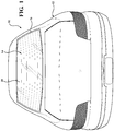
Figure 1 is an elevational view of one embodiment of a window assembly, according to the present invention, illustrated in operational relationship with a vehicle. -
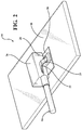
Figure 2 is a partial cross sectional perspective view of the window assembly ofFigure 1 having a portion of an encapsulation cut away. -
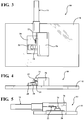
Figure 3 is a planar top view of the window assembly ofFigure 2 . -
Figure 4 is a front elevational view of the window assembly ofFigure 2 . -
Figure 5 is a side elevational view of the window assembly ofFigure 2 . - Referring to the Figures, wherein like numerals indicate like parts throughout the several views, one embodiment of a
window assembly 10, according to the present invention, is shown inFigures 1 and2 . Thewindow assembly 10 is a typically for a vehicle, generally indicated at 12, such as an automotive vehicle. As illustrated inFigure 1 , thewindow assembly 10 may be a rear window assembly having a defrost system, generally indicated at 14. It should be appreciated that thewindow assembly 10 may be used for other types of vehicles providing a connection between a wiring harness, generally indicated at 16 (Figure 2 ), and thedefrost system 14 or other components such as an antenna (not shown). - Referring to
Figures 1 and2 , one embodiment of thewindow assembly 10, according to the present invention, includes atransparent pane 18. In one embodiment, thetransparent pane 18 is made of glass. In another embodiment, thetransparent pane 18 is made of a polymethyl methacrylate, polycarbonate, polyvinyl butyral, and the like. Thewindow assembly 10 also includes anelectrical conductor 20. In one embodiment, theelectrical conductor 20 is made of silver. In other embodiments, theelectrical conductor 20 may be made of other conductive metals and/or other conductive or nonconductive materials in addition to, or instead of, silver. Theelectrical conductor 20 may be a film, a coating, and/or in any other form so long as theelectrical conductor 20 is conductive and serves any function known in the art for such electrical conductors. Theelectrical conductor 20 may be porous and/or nonporous. In various embodiments, theelectrical conductor 20 is a porous silver film. In other embodiments, theelectrical conductor 20 may be printed, for example, a printed silver film or printed silver circuit. It should be appreciated that, although theelectrical conductor 20 is shown to have a rectangular shape, theelectrical conductor 20 may have any suitable shape. - In one embodiment, the
electrical conductor 20 is disposed on thetransparent pane 18 near a peripheral edge of thetransparent pane 18. Theelectrical conductor 20 is often a component of a circuit, such as thedefrost system 14, an antenna, a defogger, or the like. It should be appreciated that theelectrical conductor 20 may be integral with the circuit or an extension of the circuit. Theelectrical conductor 20 may include one or more bus bars (not shown). It should be appreciated that thewire harness 16 transfers power from a power supply (not shown) to theelectrical conductor 20. - The
window assembly 10 also includes an electrical connection element, generally indicated at 22, that connects thewiring harness 16 and theelectrical conductor 20 for electrically coupling and operatively connecting theelectrical conductor 20 and the power supply. Theconnection element 22 is in electrical communication with theelectrical conductor 20 for energizing theelectrical conductor 20. In one embodiment, theconnection element 22 may be of copper, a copper alloy, silver, a silver alloy, or combinations thereof. In other embodiments, theconnection element 22 may also be of other metals in addition to or absent the metals described above, including, but not limited to, iron, molybdenum, tungsten, nickel, hafnium, tantalum, titanium, chromium, iridium, niobium, vanadium, platinum, tin, or combinations thereof. In one embodiment, theconnection element 22 is copper. Typically, theconnection element 22 includes aterminal connector 24 that is disposed at a distal end of thewiring harness 16. It should be appreciated that theconnection element 22 may be of other conductive metals and/or other conductive or nonconductive material. - As illustrated in
Figures 1 and2 , thewindow assembly 10 may include a layer orencapsulation 26 that encapsulates the peripheral edge of thewindow assembly 10. In one embodiment, theencapsulation 26 is made of a polymer or polymeric material. Non-limiting examples of the polymer include thermoplastic material(s) or thermoset material(s). Other non-limiting examples of the polymer include thermoplastic elastomers (TPE), thermoplastic vulcanizates (TPV), and thermoplastic polyolefins (TPO). Specific non-limiting examples include thermoplastic styrene (TPS), polyurethane, polyvinyl chloride (PVC), and ester based thermoplastic elastomers (E-TPE). It should be appreciated that, in one embodiment, theencapsulation 26 is formed from a reaction injection molding (RIM) process. It should also be appreciated that theencapsulation 26 may be made of non-polymeric materials. - The
window assembly 10 may include one or more functional components (not shown) for aligning, positioning, or guiding thewindow assembly 10 on thevehicle 12. In one example, the functional component may be a rail for allowing thewindow assembly 10 to slide on a complementary rail attached to thevehicle 12. In another example, the functional component may be a frame for mounting thewindow assembly 10 to thevehicle 12. Theencapsulation 26 attaches the functional components to thewindow assembly 10. To attach the functional component to thewindow assembly 10, theencapsulation 26 may encapsulate a portion of the functional component, thereby attaching the functional component to thewindow assembly 10. - In one embodiment, as illustrated in
Figures 2 through 5 , thewindow assembly 10 includes an electrically conductivecompressible member 28 disposed between theelectrical conductor 20 and theterminal connector 24. Thecompressible member 28 electrically couples theelectrical conductor 20 and theterminal connector 24. In addition, thecompressible member 28 is elastically deformable, and as such, stress generated by differences in the coefficients of thermal expansion of theencapsulation 26 and theelectrical conductor 20 is largely absorbed by thecompressible material 28 and not imparted onto theelectrical conductor 20. - In one embodiment, the
compressible member 28 is made of a compressible material. In one embodiment, the compressible material is a foam. The foam may be an open celled foam or a closed cell foam. More typically, the foam is a polymer, which is foamed or expanded. In certain embodiments, the polymer is a polyurethane, such that the compressible material is a polyurethane foam, e.g. closed cell polyurethane foam. In other embodiments, the polymer is rubber and formed from ethylene propylene diene monomer (EPDM), such that the compressible material is foamed EPDM. In other embodiments, the foam is polystyrene. In yet other embodiments, the polymer is a conductive polymer. Conductive polymers can also be referred to in the art as intrinsically conductive polymers (ICPs), which are polymers that can conduct electrical current or electricity. As such, when the polymer is conductive, the compressible material has conductive properties. It should be appreciated that thecompressible member 28 may also be made of an incompressible material that is physically arranged to be compressed between theterminal connector 24 and theelectrical conductor 20, for example, a steel formed into a spring shape. - The
compressible member 28 may include a conductive filler in the compressible material to establish or increase the conductive properties of the compressible material. The conductive filler can be selected from various conductive fillers understood in the art, such as metal or carbon filler, which can be in various forms such as powder or fibers. In certain embodiments, the conductive filler comprises metal, e.g. a metal powder. - In certain embodiments the
compressible member 28 includes a foil layer that is conductive and flexible disposed about the compressible material. The foil layer has a thickness that is less than the thickness of the compressible material. In other words, the foil layer is thin. The foil layer surrounds the compressible material. More specifically, the foil layer surrounds the outer periphery of the compressible material. When the foil layer is used, the foil layer may provide the conductive properties of the compressible material. As such, the foil layer may establish the conductivity of the compressible material. In other words, in certain embodiments, if the foil layer was not present, the compressible material would not have conductive properties. Typically, the foil layer is made of metal, more typically, the foil layer is made of aluminum, copper, brass, nickel, tin, carbon-based compounds, or combinations thereof. In certain embodiments, the foil layer is made of a fabric-reinforced metal, such as fabric-reinforced aluminum. It should be appreciated that the foil layer can be formed of any suitable material(s) for electrically connecting theterminal connector 24 to theelectrical conductor 20. It should also be appreciated that thecompressible member 28 made of a compressible material, e.g. polyurethane foam, including the foil layer, can also include the conductive filler and/or be formed from the conductive polymer. It should further be appreciated that thecompressible member 28 may also be a metallic sponge or metallic foam, for example, spun metal such as steel wool. - In other embodiments, the
compressible member 28 is a spring element. Typically, thecompressible member 28 is the spring element when theelectrical conductor 20 is a component in a circuit intended for low current/low voltage applications such as an antenna. - The
encapsulation 26 is disposed on theterminal connector 24 and thecompressible member 28. Disposing theencapsulation 26 on theterminal connector 24 and thecompressible member 28 ensures that theterminal connector 24 and theelectrical conductor 20 are electrically coupled and operatively connected. In addition, theencapsulation 26 holds or secures theterminal connector 24 andcompressible member 28 to theelectrical conductor 20 and thetransparent pane 18. - One advantage of the
window assembly 10 of the present invention is that thecompressible member 28 eliminates the need for solder. As described above, if solder is contained within thewindow assembly 10 and theencapsulation 26 is applied directly on the solder, then differences in the coefficients of thermal expansion can crack thetransparent pane 18 or separate theelectrical conductor 20 and theterminal connector 24. However, in thewindow assembly 10 of the present invention, no solder is needed, because thecompressible member 28 secures and electrically connects theelectrical conductor 20 and theterminal connector 24. Moreover, because thecompressible member 28 is compressible, stress generated by differences in the coefficients of thermal expansion is largely absorbed by thecompressible member 28 and not imparted onto theelectrical conductor 20. As such, replacing the solder with thecompressible member 28 produces awindow assembly 10 of the present invention that is more environmentally friendly as it is inherently lead-free due to the elimination of solder and less prone to failure. - The present invention has been described in an illustrative manner. It is to be understood that the terminology, which has been used, is intended to be in the nature of words of description rather than of limitation.
- Many modifications and variations of the present invention are possible in light of the above teachings. Therefore, the present invention may be practiced other than as specifically described.
Claims (13)
- A window assembly (10) comprising:a transparent pane (18);an electrical conductor (20) contacting said transparent pane (18);an electrical connection element (22) for energizing said electrical conductor (20); andan encapsulation (26) disposed over said electrical connection element (22) and said electrical conductor (20) to secure said electrical connection element (22) to said electrical conductor (20) and said transparent pane (18);
wherein said encapsulation (26) is disposed on said electrical connection element (22) to secure said electrical connection element (22) to said electrical conductor (20) and said transparent pane (18);
the window assembly being characterised in that it further comprisesan electrically conductive compressible member (28), disposed between said electrical connection element (22) and said electrical conductor (20), and comprising a foam material that is compressed between said electrical connection element (22) and said electrical conductor (20) for providing an electrical connection between said electrical connection element (22) and said electrical conductor (20);wherein said encapsulation (26) is disposed on an upper surface of said electrically conductive compressible member (28) to secure said electrically conductive compressible member (28) to said electrical conductor (20) and said transparent pane (18). - A window assembly (10) as set forth in claim 1 including a conductive filler in said foam material.
- A window assembly (10) as set forth in any one of claims 1 - 2 including a foil layer disposed about said foam material.
- A window assembly (10) as set forth in claim 3 wherein said foil layer is a conductive and flexible material.
- A window assembly (10) as set forth in any one of claims 1 - 4 wherein said encapsulation (26) is made of a polymeric material.
- A window assembly (10) as set forth in any one of claims 1 - 5 wherein the electrical connection between said electrical connection element (22) and said electrical conductor (20) is devoid of solder.
- A window assembly (10) as set forth in any one of claims 1 - 6 wherein said electrical connection element (22) includes a terminal connector (24) for electrical connection to said electrical conductor (20) for energizing said electrical conductor (20).
- A window assembly (10) as set forth in any one of claims 1 - 7 wherein said window assembly (10) is a solderless assembly for said transparent pane (18).
- A window assembly (10) as set forth in any one of claims 1 - 8 wherein said transparent pane (18) is made of a polymethyl methacrylate, polycarbonate, polyvinyl butyral, and the like.
- A vehicle (12) including said window assembly (10) as set forth in any one of claims 1 - 9.
- A vehicle (12) as set forth in claim 10 wherein said window assembly (10) is a rear window assembly (10).
- A vehicle (12) as set forth in claim 11 wherein said rear window assembly (10) includes a defrost system.
- A method of making a window assembly (10) as set forth in any one of claims 1 - 9 including the steps ofproviding the transparent pane (18) and the electrical connection element (22);contacting the electrical conductor (20) with the transparent pane (18);disposing the electrically conductive compressible member (28) between the electrical connection element (22) and the electrical conductor (20) and compressing the foam material between the electrical connection element (22) and the electrical conductor (20) for providing an electrical connection between the electrical connection element (22) and the electrical conductor (20); anddisposing the encapsulation (26) over the electrical connection element (22) and the electrical conductor (20) to secure the electrical connection element (22) to the electrical conductor (20) and the transparent pane (18).
Applications Claiming Priority (2)
| Application Number | Priority Date | Filing Date | Title |
|---|---|---|---|
| US201361866911P | 2013-08-16 | 2013-08-16 | |
| PCT/US2014/051250 WO2015023936A1 (en) | 2013-08-16 | 2014-08-15 | Window assembly with electrically conductive compressible member |
Publications (2)
| Publication Number | Publication Date |
|---|---|
| EP3039746A1 EP3039746A1 (en) | 2016-07-06 |
| EP3039746B1 true EP3039746B1 (en) | 2020-10-07 |
Family
ID=51453871
Family Applications (2)
| Application Number | Title | Priority Date | Filing Date |
|---|---|---|---|
| EP14761459.8A Not-in-force EP3039746B1 (en) | 2013-08-16 | 2014-08-15 | Window assembly with electrically conductive compressible member |
| EP14758228.2A Active EP3036795B1 (en) | 2013-08-16 | 2014-08-15 | Window assembly with casing for solder joint |
Family Applications After (1)
| Application Number | Title | Priority Date | Filing Date |
|---|---|---|---|
| EP14758228.2A Active EP3036795B1 (en) | 2013-08-16 | 2014-08-15 | Window assembly with casing for solder joint |
Country Status (4)
| Country | Link |
|---|---|
| US (2) | US9966673B2 (en) |
| EP (2) | EP3039746B1 (en) |
| JP (2) | JP6618907B2 (en) |
| WO (2) | WO2015023936A1 (en) |
Families Citing this family (10)
| Publication number | Priority date | Publication date | Assignee | Title |
|---|---|---|---|---|
| US9966673B2 (en) | 2013-08-16 | 2018-05-08 | Agc Automotive Americas R&D, Inc. | Window assembly with electrically conductive compressible member |
| EP3089272A1 (en) * | 2015-04-29 | 2016-11-02 | AGC Glass Europe | Glazing panel having an electrically conductive connector |
| DE202015007100U1 (en) * | 2015-10-10 | 2017-01-13 | Fractal-Technologies Dr.-Ing. Thomas Reul GmbH | Expansion Compensated Glass Solder Connector for Disk Contacting |
| US10263362B2 (en) * | 2017-03-29 | 2019-04-16 | Agc Automotive Americas R&D, Inc. | Fluidically sealed enclosure for window electrical connections |
| US10849192B2 (en) | 2017-04-26 | 2020-11-24 | Agc Automotive Americas R&D, Inc. | Enclosure assembly for window electrical connections |
| GB201804622D0 (en) * | 2018-03-22 | 2018-05-09 | Central Glass Co Ltd | Method of producing a vehicle glass assembly |
| US10374330B1 (en) | 2018-05-17 | 2019-08-06 | Agc Automotive Americas R&D, Inc. | Window assembly with solderless electrical connector |
| WO2022196270A1 (en) * | 2021-03-19 | 2022-09-22 | 富士フイルム株式会社 | Three-dimensional conductive film for transparent heaters, and method for producing three-dimensional conductive film for transparent heaters |
| WO2022258342A1 (en) * | 2021-06-08 | 2022-12-15 | Saint-Gobain Glass France | Plate arrangement with an electrical connection element |
| WO2025114229A1 (en) | 2023-11-29 | 2025-06-05 | Agc Glass Europe | A window glazing having an electrically conductive connector |
Citations (1)
| Publication number | Priority date | Publication date | Assignee | Title |
|---|---|---|---|---|
| US20130175255A1 (en) * | 2010-09-14 | 2013-07-11 | Lg Chem, Ltd. | Heating element and a manufacturing method thereof |
Family Cites Families (21)
| Publication number | Priority date | Publication date | Assignee | Title |
|---|---|---|---|---|
| JPS5140469Y2 (en) * | 1971-12-28 | 1976-10-02 | ||
| JPS59110258U (en) * | 1983-01-12 | 1984-07-25 | セントラル硝子株式会社 | Conductive glass connection terminal |
| GB2192023B (en) * | 1986-06-26 | 1990-01-04 | Pilkington Brothers Plc | An edge-encapsulated glazing module |
| JPH01158662U (en) * | 1988-04-21 | 1989-11-01 | ||
| US5897406A (en) * | 1997-08-15 | 1999-04-27 | Molex Incorporated | Electrical terminal for glass sheets |
| JP2001230616A (en) | 2000-02-18 | 2001-08-24 | Nippon Sheet Glass Co Ltd | Glass antenna device |
| DE10018276A1 (en) * | 2000-04-13 | 2001-10-25 | Saint Gobain Sekurit D Gmbh | Composite disc |
| JP4759802B2 (en) * | 2000-11-28 | 2011-08-31 | 旭硝子株式会社 | Resin windows for vehicles |
| US6861991B2 (en) | 2002-11-19 | 2005-03-01 | Delphi Technologies, Inc. | Independently mounted on-glass antenna module |
| US6878246B2 (en) * | 2003-04-02 | 2005-04-12 | Alcoa, Inc. | Nickel foam pin connections for inert anodes |
| JP2007018981A (en) | 2005-07-11 | 2007-01-25 | Nippon Sheet Glass Co Ltd | Terminal mounting structure to window glass |
| DE102005040812A1 (en) | 2005-08-27 | 2007-03-15 | Few Fahrzeugelektrikwerk Gmbh & Co. Kg | Electrical connection and method for its connection to the window of a motor vehicle |
| US7180031B1 (en) | 2005-09-19 | 2007-02-20 | Automotive Components Holdings, Llc | Electrical connection in glazing operations |
| US7510401B2 (en) * | 2006-10-12 | 2009-03-31 | Tessera, Inc. | Microelectronic component with foam-metal posts |
| EP2107641A4 (en) | 2007-01-25 | 2014-01-01 | Nippon Sheet Glass Co Ltd | Terminal sealing apparatus |
| GB0714723D0 (en) * | 2007-07-30 | 2007-09-12 | Pilkington Automotive D Gmbh | Improved electrical connector |
| FR2921520B1 (en) | 2007-09-20 | 2014-03-14 | Saint Gobain | ELECTRICAL CONNECTION ELEMENT AND GLAZING PROVIDED WITH SUCH A ELEMENT |
| JP5208816B2 (en) | 2009-03-06 | 2013-06-12 | 日本板硝子株式会社 | Glass with terminal and vehicle with glass with terminal |
| US10015842B2 (en) | 2010-10-18 | 2018-07-03 | Agc Automotive Americans Co. | Sliding window assembly |
| US20120117880A1 (en) | 2010-11-11 | 2012-05-17 | Agc Automotive Americas Co. | Sliding window assembly for a vehicle |
| US9966673B2 (en) | 2013-08-16 | 2018-05-08 | Agc Automotive Americas R&D, Inc. | Window assembly with electrically conductive compressible member |
-
2014
- 2014-08-15 US US14/912,244 patent/US9966673B2/en not_active Expired - Fee Related
- 2014-08-15 JP JP2016534859A patent/JP6618907B2/en not_active Expired - Fee Related
- 2014-08-15 EP EP14761459.8A patent/EP3039746B1/en not_active Not-in-force
- 2014-08-15 WO PCT/US2014/051250 patent/WO2015023936A1/en not_active Ceased
- 2014-08-15 JP JP2016534864A patent/JP6823456B2/en active Active
- 2014-08-15 US US14/912,256 patent/US10601149B2/en not_active Expired - Fee Related
- 2014-08-15 EP EP14758228.2A patent/EP3036795B1/en active Active
- 2014-08-15 WO PCT/US2014/051216 patent/WO2015023921A1/en not_active Ceased
Patent Citations (1)
| Publication number | Priority date | Publication date | Assignee | Title |
|---|---|---|---|---|
| US20130175255A1 (en) * | 2010-09-14 | 2013-07-11 | Lg Chem, Ltd. | Heating element and a manufacturing method thereof |
Also Published As
| Publication number | Publication date |
|---|---|
| EP3036795A1 (en) | 2016-06-29 |
| EP3036795B1 (en) | 2019-11-27 |
| JP2016537790A (en) | 2016-12-01 |
| WO2015023936A1 (en) | 2015-02-19 |
| WO2015023921A1 (en) | 2015-02-19 |
| US9966673B2 (en) | 2018-05-08 |
| US20160204524A1 (en) | 2016-07-14 |
| JP2016528705A (en) | 2016-09-15 |
| US10601149B2 (en) | 2020-03-24 |
| US20160204522A1 (en) | 2016-07-14 |
| EP3039746A1 (en) | 2016-07-06 |
| JP6618907B2 (en) | 2019-12-11 |
| JP6823456B2 (en) | 2021-02-03 |
Similar Documents
| Publication | Publication Date | Title |
|---|---|---|
| US9966673B2 (en) | Window assembly with electrically conductive compressible member | |
| JP6272936B2 (en) | Connection element | |
| JP2019200981A (en) | Window assembly having solder-less electric connector | |
| US10677579B2 (en) | Capacitive distance sensor | |
| KR20140025428A (en) | Flat-conductor connection element for an antenna structure | |
| EP3059801B1 (en) | Electricity-supplying structure, resin plate for window provided with said structure, and method for manufacturing resin plate for window provided with electricity-supplying structure | |
| KR100201675B1 (en) | Antenna connector device | |
| US20200001829A1 (en) | Window Assembly | |
| JP6914809B2 (en) | Windshield for vehicles | |
| WO2013128796A1 (en) | Seal member-equipped window glass | |
| JP2008270021A (en) | Plate with conductor and method for producing the same | |
| CN114729557A (en) | Electrified belt device | |
| JP6171876B2 (en) | FEEDING STRUCTURE AND WINDOW RESIN PLATE FORM WITH THE SAME, AND METHOD FOR MANUFACTURING WINDOW RESIN PLATE FORM WITH FEEDING STRUCTURE | |
| HK1212516A1 (en) | Electrical connector for attachment to vehicle glass | |
| US8896496B2 (en) | Configurable antenna element | |
| CN114137502B (en) | Heating wire connecting structure, window cover and manufacturing method | |
| JP2008306399A (en) | Laminated body | |
| CN117693867A (en) | Wire connections for electrical contact | |
| WO2024078937A1 (en) | An electrically conductive connector for a window pane | |
| WO2025114229A1 (en) | A window glazing having an electrically conductive connector | |
| CN119422290A (en) | Electrical wiring connection for electrical contact | |
| WO2010052202A1 (en) | Component support | |
| JP2006290153A (en) | Power supply structure for vehicles | |
| JPH0997963A (en) | Automotive circuit body |
Legal Events
| Date | Code | Title | Description |
|---|---|---|---|
| PUAI | Public reference made under article 153(3) epc to a published international application that has entered the european phase |
Free format text: ORIGINAL CODE: 0009012 |
|
| 17P | Request for examination filed |
Effective date: 20160216 |
|
| AK | Designated contracting states |
Kind code of ref document: A1 Designated state(s): AL AT BE BG CH CY CZ DE DK EE ES FI FR GB GR HR HU IE IS IT LI LT LU LV MC MK MT NL NO PL PT RO RS SE SI SK SM TR |
|
| AX | Request for extension of the european patent |
Extension state: BA ME |
|
| DAX | Request for extension of the european patent (deleted) | ||
| STAA | Information on the status of an ep patent application or granted ep patent |
Free format text: STATUS: EXAMINATION IS IN PROGRESS |
|
| 17Q | First examination report despatched |
Effective date: 20170530 |
|
| GRAP | Despatch of communication of intention to grant a patent |
Free format text: ORIGINAL CODE: EPIDOSNIGR1 |
|
| STAA | Information on the status of an ep patent application or granted ep patent |
Free format text: STATUS: GRANT OF PATENT IS INTENDED |
|
| INTG | Intention to grant announced |
Effective date: 20200330 |
|
| GRAS | Grant fee paid |
Free format text: ORIGINAL CODE: EPIDOSNIGR3 |
|
| GRAA | (expected) grant |
Free format text: ORIGINAL CODE: 0009210 |
|
| STAA | Information on the status of an ep patent application or granted ep patent |
Free format text: STATUS: THE PATENT HAS BEEN GRANTED |
|
| AK | Designated contracting states |
Kind code of ref document: B1 Designated state(s): AL AT BE BG CH CY CZ DE DK EE ES FI FR GB GR HR HU IE IS IT LI LT LU LV MC MK MT NL NO PL PT RO RS SE SI SK SM TR |
|
| REG | Reference to a national code |
Ref country code: GB Ref legal event code: FG4D |
|
| REG | Reference to a national code |
Ref country code: CH Ref legal event code: EP Ref country code: AT Ref legal event code: REF Ref document number: 1322149 Country of ref document: AT Kind code of ref document: T Effective date: 20201015 |
|
| REG | Reference to a national code |
Ref country code: IE Ref legal event code: FG4D |
|
| REG | Reference to a national code |
Ref country code: DE Ref legal event code: R096 Ref document number: 602014071009 Country of ref document: DE |
|
| REG | Reference to a national code |
Ref country code: NL Ref legal event code: MP Effective date: 20201007 |
|
| REG | Reference to a national code |
Ref country code: AT Ref legal event code: MK05 Ref document number: 1322149 Country of ref document: AT Kind code of ref document: T Effective date: 20201007 |
|
| PG25 | Lapsed in a contracting state [announced via postgrant information from national office to epo] |
Ref country code: GR Free format text: LAPSE BECAUSE OF FAILURE TO SUBMIT A TRANSLATION OF THE DESCRIPTION OR TO PAY THE FEE WITHIN THE PRESCRIBED TIME-LIMIT Effective date: 20210108 Ref country code: NL Free format text: LAPSE BECAUSE OF FAILURE TO SUBMIT A TRANSLATION OF THE DESCRIPTION OR TO PAY THE FEE WITHIN THE PRESCRIBED TIME-LIMIT Effective date: 20201007 Ref country code: PT Free format text: LAPSE BECAUSE OF FAILURE TO SUBMIT A TRANSLATION OF THE DESCRIPTION OR TO PAY THE FEE WITHIN THE PRESCRIBED TIME-LIMIT Effective date: 20210208 Ref country code: NO Free format text: LAPSE BECAUSE OF FAILURE TO SUBMIT A TRANSLATION OF THE DESCRIPTION OR TO PAY THE FEE WITHIN THE PRESCRIBED TIME-LIMIT Effective date: 20210107 Ref country code: RS Free format text: LAPSE BECAUSE OF FAILURE TO SUBMIT A TRANSLATION OF THE DESCRIPTION OR TO PAY THE FEE WITHIN THE PRESCRIBED TIME-LIMIT Effective date: 20201007 Ref country code: FI Free format text: LAPSE BECAUSE OF FAILURE TO SUBMIT A TRANSLATION OF THE DESCRIPTION OR TO PAY THE FEE WITHIN THE PRESCRIBED TIME-LIMIT Effective date: 20201007 |
|
| REG | Reference to a national code |
Ref country code: LT Ref legal event code: MG4D |
|
| PG25 | Lapsed in a contracting state [announced via postgrant information from national office to epo] |
Ref country code: BG Free format text: LAPSE BECAUSE OF FAILURE TO SUBMIT A TRANSLATION OF THE DESCRIPTION OR TO PAY THE FEE WITHIN THE PRESCRIBED TIME-LIMIT Effective date: 20210107 Ref country code: ES Free format text: LAPSE BECAUSE OF FAILURE TO SUBMIT A TRANSLATION OF THE DESCRIPTION OR TO PAY THE FEE WITHIN THE PRESCRIBED TIME-LIMIT Effective date: 20201007 Ref country code: AT Free format text: LAPSE BECAUSE OF FAILURE TO SUBMIT A TRANSLATION OF THE DESCRIPTION OR TO PAY THE FEE WITHIN THE PRESCRIBED TIME-LIMIT Effective date: 20201007 Ref country code: IS Free format text: LAPSE BECAUSE OF FAILURE TO SUBMIT A TRANSLATION OF THE DESCRIPTION OR TO PAY THE FEE WITHIN THE PRESCRIBED TIME-LIMIT Effective date: 20210207 Ref country code: PL Free format text: LAPSE BECAUSE OF FAILURE TO SUBMIT A TRANSLATION OF THE DESCRIPTION OR TO PAY THE FEE WITHIN THE PRESCRIBED TIME-LIMIT Effective date: 20201007 Ref country code: SE Free format text: LAPSE BECAUSE OF FAILURE TO SUBMIT A TRANSLATION OF THE DESCRIPTION OR TO PAY THE FEE WITHIN THE PRESCRIBED TIME-LIMIT Effective date: 20201007 Ref country code: LV Free format text: LAPSE BECAUSE OF FAILURE TO SUBMIT A TRANSLATION OF THE DESCRIPTION OR TO PAY THE FEE WITHIN THE PRESCRIBED TIME-LIMIT Effective date: 20201007 |
|
| PG25 | Lapsed in a contracting state [announced via postgrant information from national office to epo] |
Ref country code: HR Free format text: LAPSE BECAUSE OF FAILURE TO SUBMIT A TRANSLATION OF THE DESCRIPTION OR TO PAY THE FEE WITHIN THE PRESCRIBED TIME-LIMIT Effective date: 20201007 |
|
| REG | Reference to a national code |
Ref country code: DE Ref legal event code: R097 Ref document number: 602014071009 Country of ref document: DE |
|
| PG25 | Lapsed in a contracting state [announced via postgrant information from national office to epo] |
Ref country code: EE Free format text: LAPSE BECAUSE OF FAILURE TO SUBMIT A TRANSLATION OF THE DESCRIPTION OR TO PAY THE FEE WITHIN THE PRESCRIBED TIME-LIMIT Effective date: 20201007 Ref country code: CZ Free format text: LAPSE BECAUSE OF FAILURE TO SUBMIT A TRANSLATION OF THE DESCRIPTION OR TO PAY THE FEE WITHIN THE PRESCRIBED TIME-LIMIT Effective date: 20201007 Ref country code: SM Free format text: LAPSE BECAUSE OF FAILURE TO SUBMIT A TRANSLATION OF THE DESCRIPTION OR TO PAY THE FEE WITHIN THE PRESCRIBED TIME-LIMIT Effective date: 20201007 Ref country code: LT Free format text: LAPSE BECAUSE OF FAILURE TO SUBMIT A TRANSLATION OF THE DESCRIPTION OR TO PAY THE FEE WITHIN THE PRESCRIBED TIME-LIMIT Effective date: 20201007 Ref country code: RO Free format text: LAPSE BECAUSE OF FAILURE TO SUBMIT A TRANSLATION OF THE DESCRIPTION OR TO PAY THE FEE WITHIN THE PRESCRIBED TIME-LIMIT Effective date: 20201007 Ref country code: SK Free format text: LAPSE BECAUSE OF FAILURE TO SUBMIT A TRANSLATION OF THE DESCRIPTION OR TO PAY THE FEE WITHIN THE PRESCRIBED TIME-LIMIT Effective date: 20201007 |
|
| PLBE | No opposition filed within time limit |
Free format text: ORIGINAL CODE: 0009261 |
|
| STAA | Information on the status of an ep patent application or granted ep patent |
Free format text: STATUS: NO OPPOSITION FILED WITHIN TIME LIMIT |
|
| PG25 | Lapsed in a contracting state [announced via postgrant information from national office to epo] |
Ref country code: DK Free format text: LAPSE BECAUSE OF FAILURE TO SUBMIT A TRANSLATION OF THE DESCRIPTION OR TO PAY THE FEE WITHIN THE PRESCRIBED TIME-LIMIT Effective date: 20201007 |
|
| 26N | No opposition filed |
Effective date: 20210708 |
|
| PG25 | Lapsed in a contracting state [announced via postgrant information from national office to epo] |
Ref country code: IT Free format text: LAPSE BECAUSE OF FAILURE TO SUBMIT A TRANSLATION OF THE DESCRIPTION OR TO PAY THE FEE WITHIN THE PRESCRIBED TIME-LIMIT Effective date: 20201007 Ref country code: AL Free format text: LAPSE BECAUSE OF FAILURE TO SUBMIT A TRANSLATION OF THE DESCRIPTION OR TO PAY THE FEE WITHIN THE PRESCRIBED TIME-LIMIT Effective date: 20201007 |
|
| PG25 | Lapsed in a contracting state [announced via postgrant information from national office to epo] |
Ref country code: SI Free format text: LAPSE BECAUSE OF FAILURE TO SUBMIT A TRANSLATION OF THE DESCRIPTION OR TO PAY THE FEE WITHIN THE PRESCRIBED TIME-LIMIT Effective date: 20201007 |
|
| REG | Reference to a national code |
Ref country code: CH Ref legal event code: PL |
|
| PG25 | Lapsed in a contracting state [announced via postgrant information from national office to epo] |
Ref country code: MC Free format text: LAPSE BECAUSE OF FAILURE TO SUBMIT A TRANSLATION OF THE DESCRIPTION OR TO PAY THE FEE WITHIN THE PRESCRIBED TIME-LIMIT Effective date: 20201007 |
|
| REG | Reference to a national code |
Ref country code: BE Ref legal event code: MM Effective date: 20210831 |
|
| GBPC | Gb: european patent ceased through non-payment of renewal fee |
Effective date: 20210815 |
|
| PG25 | Lapsed in a contracting state [announced via postgrant information from national office to epo] |
Ref country code: LI Free format text: LAPSE BECAUSE OF NON-PAYMENT OF DUE FEES Effective date: 20210831 Ref country code: CH Free format text: LAPSE BECAUSE OF NON-PAYMENT OF DUE FEES Effective date: 20210831 |
|
| PG25 | Lapsed in a contracting state [announced via postgrant information from national office to epo] |
Ref country code: IS Free format text: LAPSE BECAUSE OF FAILURE TO SUBMIT A TRANSLATION OF THE DESCRIPTION OR TO PAY THE FEE WITHIN THE PRESCRIBED TIME-LIMIT Effective date: 20210207 Ref country code: LU Free format text: LAPSE BECAUSE OF NON-PAYMENT OF DUE FEES Effective date: 20210815 |
|
| PG25 | Lapsed in a contracting state [announced via postgrant information from national office to epo] |
Ref country code: IE Free format text: LAPSE BECAUSE OF NON-PAYMENT OF DUE FEES Effective date: 20210815 Ref country code: GB Free format text: LAPSE BECAUSE OF NON-PAYMENT OF DUE FEES Effective date: 20210815 Ref country code: FR Free format text: LAPSE BECAUSE OF NON-PAYMENT OF DUE FEES Effective date: 20210831 Ref country code: BE Free format text: LAPSE BECAUSE OF NON-PAYMENT OF DUE FEES Effective date: 20210831 |
|
| PG25 | Lapsed in a contracting state [announced via postgrant information from national office to epo] |
Ref country code: HU Free format text: LAPSE BECAUSE OF FAILURE TO SUBMIT A TRANSLATION OF THE DESCRIPTION OR TO PAY THE FEE WITHIN THE PRESCRIBED TIME-LIMIT; INVALID AB INITIO Effective date: 20140815 |
|
| PG25 | Lapsed in a contracting state [announced via postgrant information from national office to epo] |
Ref country code: CY Free format text: LAPSE BECAUSE OF FAILURE TO SUBMIT A TRANSLATION OF THE DESCRIPTION OR TO PAY THE FEE WITHIN THE PRESCRIBED TIME-LIMIT Effective date: 20201007 |
|
| PG25 | Lapsed in a contracting state [announced via postgrant information from national office to epo] |
Ref country code: MK Free format text: LAPSE BECAUSE OF FAILURE TO SUBMIT A TRANSLATION OF THE DESCRIPTION OR TO PAY THE FEE WITHIN THE PRESCRIBED TIME-LIMIT Effective date: 20201007 |
|
| PG25 | Lapsed in a contracting state [announced via postgrant information from national office to epo] |
Ref country code: MT Free format text: LAPSE BECAUSE OF FAILURE TO SUBMIT A TRANSLATION OF THE DESCRIPTION OR TO PAY THE FEE WITHIN THE PRESCRIBED TIME-LIMIT Effective date: 20201007 |
|
| PGFP | Annual fee paid to national office [announced via postgrant information from national office to epo] |
Ref country code: DE Payment date: 20240828 Year of fee payment: 11 |
|
| PG25 | Lapsed in a contracting state [announced via postgrant information from national office to epo] |
Ref country code: TR Free format text: LAPSE BECAUSE OF FAILURE TO SUBMIT A TRANSLATION OF THE DESCRIPTION OR TO PAY THE FEE WITHIN THE PRESCRIBED TIME-LIMIT Effective date: 20201007 |
|
| REG | Reference to a national code |
Ref country code: DE Ref legal event code: R119 Ref document number: 602014071009 Country of ref document: DE |
|
| PG25 | Lapsed in a contracting state [announced via postgrant information from national office to epo] |
Ref country code: DE Free format text: LAPSE BECAUSE OF NON-PAYMENT OF DUE FEES Effective date: 20260303 |