EP3038871B1 - Cylindre de frein actionné par air comprimé, présentant un trou de ventilation double flux recouvert - Google Patents
Cylindre de frein actionné par air comprimé, présentant un trou de ventilation double flux recouvert Download PDFInfo
- Publication number
- EP3038871B1 EP3038871B1 EP14758118.5A EP14758118A EP3038871B1 EP 3038871 B1 EP3038871 B1 EP 3038871B1 EP 14758118 A EP14758118 A EP 14758118A EP 3038871 B1 EP3038871 B1 EP 3038871B1
- Authority
- EP
- European Patent Office
- Prior art keywords
- wall
- bore
- brake cylinder
- cover
- spring
- Prior art date
- Legal status (The legal status is an assumption and is not a legal conclusion. Google has not performed a legal analysis and makes no representation as to the accuracy of the status listed.)
- Active
Links
- 230000008878 coupling Effects 0.000 claims description 43
- 238000010168 coupling process Methods 0.000 claims description 43
- 238000005859 coupling reaction Methods 0.000 claims description 43
- 238000007789 sealing Methods 0.000 claims description 33
- XAGFODPZIPBFFR-UHFFFAOYSA-N aluminium Chemical compound [Al] XAGFODPZIPBFFR-UHFFFAOYSA-N 0.000 claims description 7
- 229910052782 aluminium Inorganic materials 0.000 claims description 7
- 238000000034 method Methods 0.000 claims description 2
- 230000000149 penetrating effect Effects 0.000 claims description 2
- 230000008569 process Effects 0.000 claims description 2
- 230000002093 peripheral effect Effects 0.000 description 6
- 230000000740 bleeding effect Effects 0.000 description 4
- 238000004891 communication Methods 0.000 description 4
- 229920001971 elastomer Polymers 0.000 description 4
- 239000012528 membrane Substances 0.000 description 4
- 239000000806 elastomer Substances 0.000 description 3
- 238000013022 venting Methods 0.000 description 3
- 230000000694 effects Effects 0.000 description 2
- 230000006870 function Effects 0.000 description 2
- 239000000463 material Substances 0.000 description 2
- AZDRQVAHHNSJOQ-UHFFFAOYSA-N alumane Chemical group [AlH3] AZDRQVAHHNSJOQ-UHFFFAOYSA-N 0.000 description 1
- 230000000712 assembly Effects 0.000 description 1
- 238000000429 assembly Methods 0.000 description 1
- 230000001419 dependent effect Effects 0.000 description 1
- 238000011161 development Methods 0.000 description 1
- 230000018109 developmental process Effects 0.000 description 1
- 238000006073 displacement reaction Methods 0.000 description 1
- 238000005553 drilling Methods 0.000 description 1
- 230000009977 dual effect Effects 0.000 description 1
- 239000012530 fluid Substances 0.000 description 1
- 230000007246 mechanism Effects 0.000 description 1
- 238000003199 nucleic acid amplification method Methods 0.000 description 1
- 238000005192 partition Methods 0.000 description 1
- 230000001681 protective effect Effects 0.000 description 1
- 238000009423 ventilation Methods 0.000 description 1
- XLYOFNOQVPJJNP-UHFFFAOYSA-N water Substances O XLYOFNOQVPJJNP-UHFFFAOYSA-N 0.000 description 1
Images


Classifications
-
- B—PERFORMING OPERATIONS; TRANSPORTING
- B60—VEHICLES IN GENERAL
- B60T—VEHICLE BRAKE CONTROL SYSTEMS OR PARTS THEREOF; BRAKE CONTROL SYSTEMS OR PARTS THEREOF, IN GENERAL; ARRANGEMENT OF BRAKING ELEMENTS ON VEHICLES IN GENERAL; PORTABLE DEVICES FOR PREVENTING UNWANTED MOVEMENT OF VEHICLES; VEHICLE MODIFICATIONS TO FACILITATE COOLING OF BRAKES
- B60T17/00—Component parts, details, or accessories of power brake systems not covered by groups B60T8/00, B60T13/00 or B60T15/00, or presenting other characteristic features
- B60T17/08—Brake cylinders other than ultimate actuators
- B60T17/085—Spring loaded brake actuators
-
- B—PERFORMING OPERATIONS; TRANSPORTING
- B60—VEHICLES IN GENERAL
- B60T—VEHICLE BRAKE CONTROL SYSTEMS OR PARTS THEREOF; BRAKE CONTROL SYSTEMS OR PARTS THEREOF, IN GENERAL; ARRANGEMENT OF BRAKING ELEMENTS ON VEHICLES IN GENERAL; PORTABLE DEVICES FOR PREVENTING UNWANTED MOVEMENT OF VEHICLES; VEHICLE MODIFICATIONS TO FACILITATE COOLING OF BRAKES
- B60T17/00—Component parts, details, or accessories of power brake systems not covered by groups B60T8/00, B60T13/00 or B60T15/00, or presenting other characteristic features
- B60T17/04—Arrangements of piping, valves in the piping, e.g. cut-off valves, couplings or air hoses
- B60T17/043—Brake line couplings, air hoses and stopcocks
-
- B—PERFORMING OPERATIONS; TRANSPORTING
- B60—VEHICLES IN GENERAL
- B60T—VEHICLE BRAKE CONTROL SYSTEMS OR PARTS THEREOF; BRAKE CONTROL SYSTEMS OR PARTS THEREOF, IN GENERAL; ARRANGEMENT OF BRAKING ELEMENTS ON VEHICLES IN GENERAL; PORTABLE DEVICES FOR PREVENTING UNWANTED MOVEMENT OF VEHICLES; VEHICLE MODIFICATIONS TO FACILITATE COOLING OF BRAKES
- B60T17/00—Component parts, details, or accessories of power brake systems not covered by groups B60T8/00, B60T13/00 or B60T15/00, or presenting other characteristic features
- B60T17/08—Brake cylinders other than ultimate actuators
- B60T17/083—Combination of service brake actuators with spring loaded brake actuators
-
- B—PERFORMING OPERATIONS; TRANSPORTING
- B60—VEHICLES IN GENERAL
- B60T—VEHICLE BRAKE CONTROL SYSTEMS OR PARTS THEREOF; BRAKE CONTROL SYSTEMS OR PARTS THEREOF, IN GENERAL; ARRANGEMENT OF BRAKING ELEMENTS ON VEHICLES IN GENERAL; PORTABLE DEVICES FOR PREVENTING UNWANTED MOVEMENT OF VEHICLES; VEHICLE MODIFICATIONS TO FACILITATE COOLING OF BRAKES
- B60T17/00—Component parts, details, or accessories of power brake systems not covered by groups B60T8/00, B60T13/00 or B60T15/00, or presenting other characteristic features
- B60T17/08—Brake cylinders other than ultimate actuators
- B60T17/088—Mounting arrangements
Definitions
- Such a brake cylinder is for example in DE 10 2008 047 633 A1 described and is a combined service brake and spring brake cylinder, arranged in the service brake cylinder, a vents and bleedable service brake limiting service brake piston and arranged in the spring brake cylinder, operable by at least one storage spring, a ventilated and ventilated spring brake chamber limiting spring brake piston with a spring brake piston rod, wherein the spring brake piston rod projecting through a central piston rod bore of an intermediate wall between the service brake cylinder and the spring brake cylinder so that it acts on the service brake piston, and two bores are provided, a first bore and a second bore, wherein the service brake chamber via the first bore and the spring brake chamber via the second hole can be vented and both holes are formed in an overlapping region of the outer housing wall of the spring brake cylinder with a contrast inner flange of the intermediate wall.
- the first bore of the two holes therefore serves the compressed air transport for loading and bleeding the service brake chamber and the second bore the compressed air transport for loading and bleeding the spring brake chamber. Since the two holes are arranged in an overlap region, in which the wall of the spring brake cylinder overlaps the flange of the intermediate wall and the two holes are made with a certain tolerance, there is a risk that, despite as in the prior art screwed in both holes inserts for coupling Moisture and dirt from the outside penetrates into the boreholes with compressed air lines and are stored between the wall of the spring-loaded brake cylinder and the flange of the intermediate wall.
- a generic brake cylinder is in WO 2013/050329 A1 described.
- the present invention is based on the object to further develop a combined brake cylinder of the type mentioned in such a way that it has a longer life.
- the invention provides that
- the at least one bore is covered by the protective cover, so that no more water and dirt can penetrate between the outer wall and the inner wall, because the bore edge is surrounded by the cover in the circumferential direction completely and sealingly surrounded.
- the coupling part is additionally formed on her, which is anyway required in the bore to connect a partner coupling part releasably, which is connected to a compressed air line.
- the cover has at least one circumferentially circumferential sealing element, which is pressed by means of the axial forces caused by the attachment of the cover on the outer wall against the outer surface of the outer wall and thereby elastically deformed.
- the sealing element can then be formed, for example, by at least one sealing rib integral with the cover and circumferential in the circumferential direction or by a sealing ring, for example made of elastomer, mounted on the cover and circulating in the circumferential direction.
- the cover is preferably made of aluminum, then on the one hand it has the necessary rigidity and material hardness that compressed air hoses loaded with transverse forces can be connected to it or to the coupling part accommodated in the bore.
- aluminum is soft enough so that one with the cover, for example, integrally formed and facing the outer surface of the outer wall circumferential circumferential sealing rib can be deformed by the axial forces resulting from the attachment so that the contact line or surface between the sealing rib and the Outer surface of the outer wall seals.
- an elastic sealing element e.g. a sealing ring made of elastomer may be accommodated in a circumferential groove facing the outer surface of the outer wall surface of the cover, which then seals against this outer surface.
- At least one sealing element sealing against a radially inner surface of the at least one bore may be provided on a radially outer peripheral surface of the coupling part in order to prevent dirt and moisture from penetrating into the interior of the brake cylinder.
- the coupling part with the cover is made in one piece, for. as aluminum die-cast part.
- the cover is attached to the outer wall by means of screws projecting through the cover screws, which are then countered in threaded holes in the outer wall.
- the cover could be locked to the outer wall by means of a detent.
- any attachment options are conceivable, which ensure a sufficient contact pressure of the cover to the outer surface of the outer wall.
- the brake cylinder is a combined service brake and spring brake cylinder, a so-called.
- Combined cylinder with an im A service brake cylinder arranged, a serviceable and ventable service brake chamber limiting service brake piston and arranged in the spring brake, operable by at least one storage spring and ventable spring brake chamber limiting spring brake piston with a Feder arrivedbremskolbenstange, the Feder namedbremskolbenstange by a central piston rod bore an intermediate wall between the service brake cylinder and the spring brake cylinder such projects that it acts on the service brake piston, and two bores are provided, a first bore and a second bore, wherein the service brake chamber via the first bore and the spring brake chamber via the second bore are aerated and vented, and wherein a portion of the housing wall of Feder arrivedsbremszylinders the outer wall and a radially outer flange of the intermediate wall forms the inner wall, and the cover two Kuppl has unarts, of which a first coupling part protrudes into
- the first bore is particularly preferably a through hole drilled through the housing wall of the spring brake cylinder and the flange
- the second bore is a through bore passing through the housing wall of the spring brake cylinder, which is continued in the flange as a blind hole.
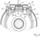
- Fig.1 is a combined service brake and spring brake cylinder 1, hereinafter called combination cylinder shown.
- the combination cylinder 1 consists of a service brake cylinder 2 and a structurally and functionally connected spring brake cylinder 4.
- the service brake cylinder 2 and the spring brake cylinder 4 are separated by an intermediate wall 6 from each other.
- a spring brake piston 8 is slidably disposed, wherein on one side of the spring brake piston 8, a storage spring 10 is present.
- the accumulator spring 10 is supported on its opposite side at the bottom of the spring brake cylinder 4.
- a spring brake chamber 12 is formed, which communicates with a not shown for reasons of scale pressure control module in connection to ventilate and vent.
- the spring brake piston 8 is connected to a hollow spring brake piston rod 18, which extends through the intermediate wall 6 in a service brake chamber 20 of the service brake cylinder 2.
- An inserted in a central bore 21 of the intermediate wall 6 seal assembly 22 seals against the outer wall of the spring brake piston rod 18 during their longitudinal movement.
- In the service brake chamber 20 opens an inlet, not shown, through which compressed air is admitted and discharged for actuating the service brake cylinder 2.
- the compressed air acts on a diaphragm 24 inserted within the service brake cylinder 2, on whose opposite side a thrust piece in the form of a stiff diaphragm plate 26 is provided. More specifically, the diaphragm 24 separates the pressure-relieving and releasable service brake chamber 20 of the service brake cylinder 2 from a spring chamber 31 accommodating a return spring 30 supported on the diaphragm plate 26.
- the diaphragm plate 26 is connected to a push rod 28 which cooperates with a brake actuating mechanism outside of the combination cylinder 1.
- a brake actuating mechanism outside of the combination cylinder 1.
- This may be, for example, actuators of a disc brake of a motor vehicle.
- the service brake cylinder 2 is an active brake cylinder, i. that the service brake is applied by venting the service brake chamber 20 and released by venting.
- the on the one hand on the diaphragm plate 26 and on the other hand at the bottom of the service brake cylinder 2 supporting return spring 30 ensures that the push rod 28 is retrieved at vented service brake chamber 20 in the release position.
- a radially outer fastening edge 32 of the membrane 24 has a wedge-shaped, tapering radially inward cross-section.
- This radially outer fastening edge 32 of the membrane 24 with the wedge-shaped, radially inwardly tapering cross section is clamped in a complementarily shaped receptacle 34 with wedge-shaped, radially outwardly flared cross section between the intermediate wall 6 and the service brake cylinder 2.
- the intermediate wall 6 and the service brake cylinder 2 form their outer edges as radially outwardly bent flanges 36, 38, whose mutually facing inner surfaces form the receptacle 34 with a wedge-shaped cross section between them.
- centering ring 40 is arranged substantially perpendicular to a center plane of the fastening edge 32 and protrudes, for example, on one side away from the membrane 24. It is also conceivable, however, that instead of this one centering ring 40 or additionally another, in the direction of the spring brake cylinder 4 projecting and centering against the radially inner peripheral surface of the wall 50 centering ring is provided.
- the radially inner peripheral surface 42 of the service brake cylinder 2, against which the centering ring 40 is centered preferably on an imaginary cylinder whose central axis is coaxial with the cylinder axis 46.
- the centering ring 40 can, as seen in the circumferential direction, be formed completely circumferentially or consisting of ring sections.
- the diaphragm 24 is preferably made of rubber and the centering ring 40 formed integrally with it.
- an axial component having clamping force of the mutually clamped intermediate wall 6 and service brake cylinder 2 ensures that the centering ring 40 of the diaphragm 24 is pressed against the radially inner peripheral surface 42 of the wall 44 of the service brake cylinder 2.
- the axial component of the clamping force ensures that the fastening edge 32 is pulled radially outwardly due to the wedge effect and thereby the centering ring 40 is pressed with a higher radial force against the radially inner circumferential surface 42 of the wall 44 of the service brake cylinder 2 in the sense of self-amplification of the centering becomes.
- Such an axial clamping force component can be realized, for example, by the edge of the service brake cylinder forming a flange 36 2 and the flange 38 of the intermediate wall 6 are overlapped by an edge 48 of the wall 50 of the spring brake cylinder 4 by a flange 52, which is produced for example by a forming process. This flange 52 then provides the axial component of the clamping force.
- a first bore 54 thereby extends through the flange 38 of the intermediate wall 6, while a second bore 56 as a blind hole although protruding to the flange 38 of the intermediate wall 6, but then formed in a flange 38 and in Fig.2 invisible transverse channel opens, which is in communication with the spring brake chamber 12.
- the first bore passes through the flange 38 of the intermediate wall 6 and opens directly into the service brake chamber 20.
- the first bore 54 is therefore the compressed air transport for loading and bleeding the service brake chamber 20 and the second bore 56 the compressed air transport for loading and bleeding the spring brake chamber 12th ,
- both holes 54, 56 are arranged in an overlap region 58, in which the wall 50 of the spring brake cylinder 4 overlaps the flange 38 of the intermediate wall 6 and the two bores 54, 56 are manufactured with a certain tolerance, there is a risk that, for example As in the prior art in both holes 54, 56 screwed inserts for coupling with compressed air lines moisture and dirt from the outside into the holes 54, 56 penetrates and then intercalated between the wall 50 of the spring brake cylinder 4 and the flange 38 of the intermediate wall 6.
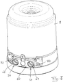
- a fixed to the wall 50 of the spring brake cylinder 4 cover 60 is provided, which extends completely circumferentially radially beyond the bore edges of the two holes 54, 56 and an outer surface 62 of the wall 50 of the spring brake cylinder 4 in a completely circumferential manner sealing contacted.
- coaxially projecting sleeve-shaped and cylindrical coupling parts 64, 66 are formed on the cover 60, a first coupling part 64 and a second coupling part 66, which are each provided for releasable connection to a not shown here partner coupling part ,
- the partner coupling parts are each connected to a compressed air line or to a pneumatic tube.
- the two coupling parts 64, 66 are releasably connected with their associated partner coupling parts, via the coupling parts 64, 66 to direct compressed air into and out of the two holes 54, 56 and on the one hand the service brake chamber 20 and on the other hand, the spring brake chamber 12 ventilate and vent.
- first coupling part 64 projects into the first bore 54 and the second coupling part 66 into the second bore 56 coaxially.
- the coupling parts 64, 66 are integral with the cover 60, e.g. as a single die-cast aluminum part.
- Both coupling parts 64, 66 preferably pass completely through the wall 50 of the spring brake cylinder 4 and open into axial sections of the bores 54, 56 in the flange 38 of the intermediate wall 6 which are not covered by the coupling parts 64, 66.
- the first coupling part 64 is in service brake chamber 20 and second coupling part 66 with the spring brake chamber 12 in flow communication, so that both chambers 12, 20 via the coupling parts 64, 66 and through which these receiving bores 54, 56 are aerated and vented.
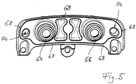
- the cover 60 preferably has a circumferentially circumferential sealing element 68, which by means of caused by the attachment of the cover 60 on the wall 50 of the spring brake cylinder 4 caused axial forces against the outer surface 62 of the wall 50 of the spring brake cylinder 4 and thereby elastically deformed ( Figure 6 ).
- the sealing element 68 is formed for example by a one-piece with the cover 60 and in the circumferential direction preferably on the outer circumference of the cover 60 circumferential sealing rib, which faces the outer surface 62 of the wall 50 of the spring brake cylinder 4.
- the cover 60 is preferably made of aluminum, for example as an aluminum die-cast part. Then, on the one hand, it has the necessary rigidity and material hardness that compressed-air hoses loaded with transverse forces can be connected to it or to the coupling parts 64, 66 received in the bores 54, 56.
- aluminum is soft enough so that, for example, integrally formed with the cover 60 and facing the outer surface 62 of the wall 50 of the spring brake cylinder 4 and circumferential circumferential sealing rib 68 by the attachment (eg by screws 72) originating axial forces in particular in the transverse direction so can be deformed such that the contact line or surface between the sealing rib 68 and the outer surface 62 of the wall 50 of the spring brake cylinder 4 seals Figure 6 shows.
- This sealing rib 68 is then preferably arranged on the outer circumference of the cover 60 ( Figure 5 . Figure 6 ).
- the cover 60 is preferably fastened to the wall 50 of the spring brake cylinder 4 by means of screws 72 projecting through screw eyes 74 of the cover 60, which are then countered by threads in bores in the wall 50 of the spring brake cylinder 4 or in the flange 38 of the intermediate wall 6.
- the combination cylinder 1 with attached to it cover 60 is then in perspective in Figure 3 shown.
- the sealing rib 68 surrounds or wraps around the screw eyes (FIG. Figure 4 ), so that in this way no moisture or dirt from the outside can penetrate into the holes 54, 56.
- a sealing element 76 sealing against the radially inner surface of the respective bore 54, 56 may be provided to prevent dirt and moisture from entering the interior of the combination cylinder 1.
- This sealing element 76 preferably consists in each case in a sealing ring made of elastomer, which is received in a radially outer groove of the respective coupling part 64, 66, as shown in FIG Figure 4 evident.
Landscapes
- Engineering & Computer Science (AREA)
- Transportation (AREA)
- Mechanical Engineering (AREA)
- Braking Arrangements (AREA)
Claims (9)
- Cylindre (1) de frein à actionnement par air comprimé pour des installations de freinage de véhicule, qui a ce qui suit :a) au moins une chambre (12, 20) de frein, qui peut être alimentée en air et purgée d'air et qui est délimitée par un piston de frein mobile ou par une membrane (8, 24) de frein,b) au moins deux parois (38, 50) du cylindre (1) de frein se recouvrant dans une région (58) de recouvrement, dont l'une (50) est une paroi extérieure en contact avec l'atmosphère par sa surface (62) extérieure et dont l'autre (38) est une paroi intérieure, qui est en contact, au moins par endroit, avec la paroi (50) extérieure sur sa surface intérieure tournée vers l'intérieur,c) un trou (54, 56), qui est constitué dans la région (58) de recouvrement, qui, en tant que trou traversant, traverse au moins la paroi (50) extérieure et qui est en liaison d'écoulement avec la au moins une chambre (12, 20) de freinage,
caractérisé en ce qued) il est prévu un recouvrement, qui est fixé au moins à la paroi (50) extérieure, qui s'étend complètement radialement en faisant le tour au-delà d'un bord extérieur du au moins un trou (54, 56) et qui est en contact avec étanchéité d'une manière faisant complètement le tour avec la surface (62) extérieure de la paroi (50) extérieure, dans lequele) sur le recouvrement (60), est constituée une partie (64, 66) d'accouplement en forme de manchon et cylindrique pénétrant coaxialement, au moins en partie, dans le au moins un trou (54, 56), partie (64, 66) d'accouplement qui est prévue, pour le raccordement amovible, à une partie d'accouplement partenaire, laquelle est reliée à un conduit pneumatique ou à un tuyau pneumatique, dans lequelf) la partie (64,66) d'accouplement traverse au moins la paroi (50) extérieure et est en liaison d'écoulement avec la au moins une chambre (12, 20) de frein. - Cylindre de frein à actionnement par air comprimé suivant la revendication 1, caractérisé en ce que le recouvrement (60) a au moins un élément (68) d'étanchéité, qui fait le tour dans la direction périphérique et qui, au moyen des forces axiales provoquées par la fixation de recouvrement (60) à la paroi (50) extérieure, est pressé sur la surface (62) extérieure de la paroi (50) extérieure et est ainsi déformé élastiquement.
- Cylindre de frein à actionnement par air comprimé suivant la revendication 2, caractérisé en ce que l'élément (68) d'étanchéité est formé par au moins une nervure d'étanchéité d'une seule pièce avec le recouvrement et faisant le tour dans la direction périphérique ou par une bague d'étanchéité montée sur le recouvrement (60) et faisant le tour dans la direction périphérique.
- Cylindre de frein à actionnement par air comprimé suivant l'une des revendications précédentes, caractérisé en ce qu'il est prévu, sur une surface périphérique extérieure radialement de la partie (64, 66) d'accouplement, au moins un élément (76) d'étanchéité rendant étanche par rapport à une surface intérieure radialement du au moins un trou (54, 56).
- Cylindre de frein à actionnement par air comprimé suivant l'une des revendications précédentes, caractérisé en ce que la partie (64, 66) d'accouplement est réalisée d'une seule pièce avec le recouvrement (60).
- Cylindre de frein à actionnement par air comprimé suivant l'une des revendications précédentes, caractérisé en ce que le recouvrement (60) est en aluminium.
- Cylindre de frein à actionnement par air comprimé suivant l'une des revendications précédentes, caractérisé en ce que le recouvrement (60) est fixé au moins à la paroi (50) extérieure à l'aide de vis (72) passant dans des trous de vissage du recouvrement (60).
- Cylindre de frein à actionnement par air comprimé suivant l'une des revendications précédentes, caractérisé en ce que c'est un cylindre (1) de frein combiné de frein de service et à ressort accumulateur, comprenanta) un piston (26) de frein de service disposé dans un cylindre (2) de frein de service et délimitant une chambre (20) de frein de service pouvant être alimentée en air et purgée d'air, ainsi queb) un piston (8) de frein à ressort accumulateur disposé dans le cylindre (4) de frein à ressort accumulateur, pouvant être actionné par au moins un ressort (10) accumulateur, délimitant une chambre (12) de frein à ressort accumulateur pouvant être alimentée en air et purgée et ayant une tige (18) de piston de frein de ressort accumulateur, dans lequelc) la tige (18) de piston de frein à ressort accumulateur pénètre par un trou (21) de tige de piston central d'une paroi (6) intermédiaire entre le cylindre (2) de frein de service et le cylindre (4) de frein à ressort accumulateur, de manière à agir sur le piston (26) de frein de service etd) il est prévu deux trous (54, 56), un premier trou (54) et un deuxième trou (56), la chambre (20) de frein de service pouvant être alimentée en air et purgée d'air par le premier tour (54) et la chambre (12) de frein à ressort accumulateur par le deuxième trou (56), dans lequele) une partie de la paroi (50) du cylindre (4) de frein à ressort accumulateur forme la paroi extérieure et une bride (38) extérieure radialement de la paroi (6) intermédiaire la paroi intérieure etf) le recouvrement (60) a deux parties (64, 66) d'accouplement, dont une première partie (64) d'accouplement pénètre dans le premier trou (54) et une deuxième partie (66) d'accouplement dans le deuxième trou (56).
- Cylindre de frein à actionnement par air comprimé suivant la revendication 8, caractérisé en ce que le premier trou (54) est un trou traversant la paroi (50) du cylindre (4) de frein à ressort accumulateur et la bride (38) et le deuxième trou (56) est un trou traversant passant à travers la paroi (50) du cylindre (4) de frein à ressort accumulateur et se poursuivant dans la bride (38) sous la forme d'un trou borgne.
Applications Claiming Priority (2)
| Application Number | Priority Date | Filing Date | Title |
|---|---|---|---|
| DE102013014449.3A DE102013014449A1 (de) | 2013-08-30 | 2013-08-30 | Druckluftbetätigter Bremszylinder mit abgedeckter Be- und Entlüftungsbohrung |
| PCT/EP2014/068220 WO2015028535A2 (fr) | 2013-08-30 | 2014-08-28 | Cylindre de frein actionné par air comprimé, présentant un trou de ventilation double flux recouvert |
Publications (2)
| Publication Number | Publication Date |
|---|---|
| EP3038871A2 EP3038871A2 (fr) | 2016-07-06 |
| EP3038871B1 true EP3038871B1 (fr) | 2017-10-18 |
Family
ID=51453739
Family Applications (1)
| Application Number | Title | Priority Date | Filing Date |
|---|---|---|---|
| EP14758118.5A Active EP3038871B1 (fr) | 2013-08-30 | 2014-08-28 | Cylindre de frein actionné par air comprimé, présentant un trou de ventilation double flux recouvert |
Country Status (3)
| Country | Link |
|---|---|
| EP (1) | EP3038871B1 (fr) |
| DE (1) | DE102013014449A1 (fr) |
| WO (1) | WO2015028535A2 (fr) |
Cited By (1)
| Publication number | Priority date | Publication date | Assignee | Title |
|---|---|---|---|---|
| US11866016B2 (en) | 2020-09-10 | 2024-01-09 | Industrial Machine Service, Inc. | Gas-liquid separating gas exchange device |
Families Citing this family (1)
| Publication number | Priority date | Publication date | Assignee | Title |
|---|---|---|---|---|
| EP4279347A1 (fr) * | 2022-05-17 | 2023-11-22 | Arfesan Arkan Fren Elemanlari Sanayi Ve Ticaret A.S. | Appareil de connexion d'air |
Family Cites Families (5)
| Publication number | Priority date | Publication date | Assignee | Title |
|---|---|---|---|---|
| US3453030A (en) * | 1965-06-22 | 1969-07-01 | Rockwell Standard Co | Vehicle brake system |
| US3411417A (en) * | 1967-01-31 | 1968-11-19 | Certain Teed Prod Corp | Add-on brake actuator with mechanical release feature |
| DE102005018038A1 (de) * | 2005-04-19 | 2006-10-26 | Knorr-Bremse Systeme für Nutzfahrzeuge GmbH | Befestigungsvorrichtung zum äußeren Befestigen von Kabeln oder Leitungen an Gehäusen |
| DE102008047633A1 (de) | 2008-09-17 | 2010-04-15 | Knorr-Bremse Systeme für Nutzfahrzeuge GmbH | Kombinierter Betriebsbrems- und Federspeicherbremszylinder mit aus einem Führungsring und wenigstens einem Dichtungselement bestehenden Dichtungsanordnungen |
| DE102011115122A1 (de) * | 2011-10-07 | 2013-04-11 | Knorr-Bremse Systeme für Nutzfahrzeuge GmbH | Kombinierter Betriebsbrems- und Federspeicherbremszylinder mit Bajonettverschluss |
-
2013
- 2013-08-30 DE DE102013014449.3A patent/DE102013014449A1/de not_active Withdrawn
-
2014
- 2014-08-28 EP EP14758118.5A patent/EP3038871B1/fr active Active
- 2014-08-28 WO PCT/EP2014/068220 patent/WO2015028535A2/fr active Application Filing
Non-Patent Citations (1)
| Title |
|---|
| None * |
Cited By (1)
| Publication number | Priority date | Publication date | Assignee | Title |
|---|---|---|---|---|
| US11866016B2 (en) | 2020-09-10 | 2024-01-09 | Industrial Machine Service, Inc. | Gas-liquid separating gas exchange device |
Also Published As
| Publication number | Publication date |
|---|---|
| DE102013014449A1 (de) | 2015-03-05 |
| WO2015028535A3 (fr) | 2015-10-22 |
| WO2015028535A2 (fr) | 2015-03-05 |
| EP3038871A2 (fr) | 2016-07-06 |
Similar Documents
| Publication | Publication Date | Title |
|---|---|---|
| DE102008061354B4 (de) | Federspeicherbremszylinder mit einer einen Führungsring mit radial äußeren Ausnehmungen beinhaltenden Dichtungsanordnung | |
| DE102005047872B3 (de) | Kombinierter Betriebsbrems- und Federspeicherbremszylinder mit innerer Entlüftung | |
| EP2864169B1 (fr) | Cylindre de frein à ressort accumulateur muni d'une soupape combinée à membrane d'entrée et de sortie | |
| DE102013114897A1 (de) | Federspeicherbremszylinder mit Notlöseeinrichtung | |
| EP1910144B1 (fr) | Cylindre combine de frein a accumulation et de frein de service a ventilation interne | |
| EP2686573B1 (fr) | Dispositif de freinage d'un véhicule sur rails doté d'une unité mâchoire de frein sollicitée en position neutre par ressort | |
| DE102006005031B4 (de) | Federspeicherbremszylinder mit einer mit Ausnehmungen versehenen Federspeicherbremskolbendichtung | |
| EP2686574A1 (fr) | Cylindre de frein pneumatique à conduit d'écoulement en labyrinthe | |
| WO1997001469A1 (fr) | Elements d'etancheite loges dans un maitre-cylindre | |
| DE102005061353A1 (de) | Pneumatischer Bremskraftverstärker | |
| EP2276656B1 (fr) | Cylindre de frein pour des freins actionnés par air comprimé de véhicules | |
| EP3038871B1 (fr) | Cylindre de frein actionné par air comprimé, présentant un trou de ventilation double flux recouvert | |
| EP0452621B1 (fr) | Cylindre de frein de service et à ressort combiné pour systèmes de freinage de véhicules, notamment véhicules utilitaires | |
| EP3806977A2 (fr) | Interface d'étanchéité pour cartouche de dessiccation d'air et socle pour cartouche de dessiccation d'air | |
| EP3114365B1 (fr) | Amplificateur de force d'embrayage comprenant des moyens d'étanchéité dynamiques spécifiques disposés dans la zone de la tige de piston | |
| EP2376318B1 (fr) | Cylindre de frein à ressort accumulateur à ventilation extérieure | |
| EP2125468B1 (fr) | Membrane pour cylindres de frein à commande par fluide sous pression, avec anneau de centrage | |
| EP2353954A1 (fr) | Cylindre de freinage d'accumulateur à ressort doté d'au moins un joint comprenant une rainure périphérique | |
| WO2002009992A1 (fr) | Maitre-cylindre de frein a pistons plongeurs aspirants et gorges radiales integrees dans le carter pour recevoir les joints d'etancheite | |
| DE102006015850A1 (de) | Vorrichtung zur Bremsbestätigung eines Kraftfahrzeuges | |
| DE102011102301A1 (de) | Hydraulikzylinder | |
| DE102014102838A1 (de) | Bewegungsdichtung zum Dichten einer zentralen Kolbenstange eines Bremszylinderkolbens eines Bremszylinders | |
| WO1990012714A2 (fr) | Maître-cylindre pour systemes hydrauliques de freinage et de freins de direction | |
| DE4209648A1 (de) | Betätigungseinheit für eine hydraulische Kraftfahrzeugbremsanlage | |
| DE102013206737A1 (de) | Axialkolbenmaschine in Schrägscheibenbauweise |
Legal Events
| Date | Code | Title | Description |
|---|---|---|---|
| PUAI | Public reference made under article 153(3) epc to a published international application that has entered the european phase |
Free format text: ORIGINAL CODE: 0009012 |
|
| 17P | Request for examination filed |
Effective date: 20160422 |
|
| AK | Designated contracting states |
Kind code of ref document: A2 Designated state(s): AL AT BE BG CH CY CZ DE DK EE ES FI FR GB GR HR HU IE IS IT LI LT LU LV MC MK MT NL NO PL PT RO RS SE SI SK SM TR |
|
| AX | Request for extension of the european patent |
Extension state: BA ME |
|
| DAX | Request for extension of the european patent (deleted) | ||
| GRAP | Despatch of communication of intention to grant a patent |
Free format text: ORIGINAL CODE: EPIDOSNIGR1 |
|
| INTG | Intention to grant announced |
Effective date: 20170516 |
|
| RIN1 | Information on inventor provided before grant (corrected) |
Inventor name: HEMERY, FRANK |
|
| GRAS | Grant fee paid |
Free format text: ORIGINAL CODE: EPIDOSNIGR3 |
|
| GRAA | (expected) grant |
Free format text: ORIGINAL CODE: 0009210 |
|
| AK | Designated contracting states |
Kind code of ref document: B1 Designated state(s): AL AT BE BG CH CY CZ DE DK EE ES FI FR GB GR HR HU IE IS IT LI LT LU LV MC MK MT NL NO PL PT RO RS SE SI SK SM TR |
|
| REG | Reference to a national code |
Ref country code: GB Ref legal event code: FG4D Free format text: NOT ENGLISH |
|
| REG | Reference to a national code |
Ref country code: CH Ref legal event code: EP |
|
| REG | Reference to a national code |
Ref country code: AT Ref legal event code: REF Ref document number: 937650 Country of ref document: AT Kind code of ref document: T Effective date: 20171115 Ref country code: IE Ref legal event code: FG4D Free format text: LANGUAGE OF EP DOCUMENT: GERMAN |
|
| REG | Reference to a national code |
Ref country code: DE Ref legal event code: R096 Ref document number: 502014005884 Country of ref document: DE |
|
| REG | Reference to a national code |
Ref country code: NL Ref legal event code: MP Effective date: 20171018 |
|
| REG | Reference to a national code |
Ref country code: LT Ref legal event code: MG4D |
|
| PG25 | Lapsed in a contracting state [announced via postgrant information from national office to epo] |
Ref country code: NL Free format text: LAPSE BECAUSE OF FAILURE TO SUBMIT A TRANSLATION OF THE DESCRIPTION OR TO PAY THE FEE WITHIN THE PRESCRIBED TIME-LIMIT Effective date: 20171018 |
|
| PG25 | Lapsed in a contracting state [announced via postgrant information from national office to epo] |
Ref country code: NO Free format text: LAPSE BECAUSE OF FAILURE TO SUBMIT A TRANSLATION OF THE DESCRIPTION OR TO PAY THE FEE WITHIN THE PRESCRIBED TIME-LIMIT Effective date: 20180118 Ref country code: FI Free format text: LAPSE BECAUSE OF FAILURE TO SUBMIT A TRANSLATION OF THE DESCRIPTION OR TO PAY THE FEE WITHIN THE PRESCRIBED TIME-LIMIT Effective date: 20171018 Ref country code: LT Free format text: LAPSE BECAUSE OF FAILURE TO SUBMIT A TRANSLATION OF THE DESCRIPTION OR TO PAY THE FEE WITHIN THE PRESCRIBED TIME-LIMIT Effective date: 20171018 Ref country code: ES Free format text: LAPSE BECAUSE OF FAILURE TO SUBMIT A TRANSLATION OF THE DESCRIPTION OR TO PAY THE FEE WITHIN THE PRESCRIBED TIME-LIMIT Effective date: 20171018 Ref country code: SE Free format text: LAPSE BECAUSE OF FAILURE TO SUBMIT A TRANSLATION OF THE DESCRIPTION OR TO PAY THE FEE WITHIN THE PRESCRIBED TIME-LIMIT Effective date: 20171018 |
|
| PG25 | Lapsed in a contracting state [announced via postgrant information from national office to epo] |
Ref country code: IS Free format text: LAPSE BECAUSE OF FAILURE TO SUBMIT A TRANSLATION OF THE DESCRIPTION OR TO PAY THE FEE WITHIN THE PRESCRIBED TIME-LIMIT Effective date: 20180218 Ref country code: RS Free format text: LAPSE BECAUSE OF FAILURE TO SUBMIT A TRANSLATION OF THE DESCRIPTION OR TO PAY THE FEE WITHIN THE PRESCRIBED TIME-LIMIT Effective date: 20171018 Ref country code: HR Free format text: LAPSE BECAUSE OF FAILURE TO SUBMIT A TRANSLATION OF THE DESCRIPTION OR TO PAY THE FEE WITHIN THE PRESCRIBED TIME-LIMIT Effective date: 20171018 Ref country code: BG Free format text: LAPSE BECAUSE OF FAILURE TO SUBMIT A TRANSLATION OF THE DESCRIPTION OR TO PAY THE FEE WITHIN THE PRESCRIBED TIME-LIMIT Effective date: 20180118 Ref country code: LV Free format text: LAPSE BECAUSE OF FAILURE TO SUBMIT A TRANSLATION OF THE DESCRIPTION OR TO PAY THE FEE WITHIN THE PRESCRIBED TIME-LIMIT Effective date: 20171018 Ref country code: GR Free format text: LAPSE BECAUSE OF FAILURE TO SUBMIT A TRANSLATION OF THE DESCRIPTION OR TO PAY THE FEE WITHIN THE PRESCRIBED TIME-LIMIT Effective date: 20180119 |
|
| REG | Reference to a national code |
Ref country code: DE Ref legal event code: R097 Ref document number: 502014005884 Country of ref document: DE |
|
| PG25 | Lapsed in a contracting state [announced via postgrant information from national office to epo] |
Ref country code: CZ Free format text: LAPSE BECAUSE OF FAILURE TO SUBMIT A TRANSLATION OF THE DESCRIPTION OR TO PAY THE FEE WITHIN THE PRESCRIBED TIME-LIMIT Effective date: 20171018 Ref country code: SK Free format text: LAPSE BECAUSE OF FAILURE TO SUBMIT A TRANSLATION OF THE DESCRIPTION OR TO PAY THE FEE WITHIN THE PRESCRIBED TIME-LIMIT Effective date: 20171018 Ref country code: EE Free format text: LAPSE BECAUSE OF FAILURE TO SUBMIT A TRANSLATION OF THE DESCRIPTION OR TO PAY THE FEE WITHIN THE PRESCRIBED TIME-LIMIT Effective date: 20171018 Ref country code: DK Free format text: LAPSE BECAUSE OF FAILURE TO SUBMIT A TRANSLATION OF THE DESCRIPTION OR TO PAY THE FEE WITHIN THE PRESCRIBED TIME-LIMIT Effective date: 20171018 |
|
| PLBE | No opposition filed within time limit |
Free format text: ORIGINAL CODE: 0009261 |
|
| REG | Reference to a national code |
Ref country code: FR Ref legal event code: PLFP Year of fee payment: 5 |
|
| STAA | Information on the status of an ep patent application or granted ep patent |
Free format text: STATUS: NO OPPOSITION FILED WITHIN TIME LIMIT |
|
| PG25 | Lapsed in a contracting state [announced via postgrant information from national office to epo] |
Ref country code: RO Free format text: LAPSE BECAUSE OF FAILURE TO SUBMIT A TRANSLATION OF THE DESCRIPTION OR TO PAY THE FEE WITHIN THE PRESCRIBED TIME-LIMIT Effective date: 20171018 Ref country code: PL Free format text: LAPSE BECAUSE OF FAILURE TO SUBMIT A TRANSLATION OF THE DESCRIPTION OR TO PAY THE FEE WITHIN THE PRESCRIBED TIME-LIMIT Effective date: 20171018 Ref country code: SM Free format text: LAPSE BECAUSE OF FAILURE TO SUBMIT A TRANSLATION OF THE DESCRIPTION OR TO PAY THE FEE WITHIN THE PRESCRIBED TIME-LIMIT Effective date: 20171018 Ref country code: IT Free format text: LAPSE BECAUSE OF FAILURE TO SUBMIT A TRANSLATION OF THE DESCRIPTION OR TO PAY THE FEE WITHIN THE PRESCRIBED TIME-LIMIT Effective date: 20171018 |
|
| 26N | No opposition filed |
Effective date: 20180719 |
|
| PG25 | Lapsed in a contracting state [announced via postgrant information from national office to epo] |
Ref country code: MT Free format text: LAPSE BECAUSE OF FAILURE TO SUBMIT A TRANSLATION OF THE DESCRIPTION OR TO PAY THE FEE WITHIN THE PRESCRIBED TIME-LIMIT Effective date: 20171018 |
|
| PG25 | Lapsed in a contracting state [announced via postgrant information from national office to epo] |
Ref country code: SI Free format text: LAPSE BECAUSE OF FAILURE TO SUBMIT A TRANSLATION OF THE DESCRIPTION OR TO PAY THE FEE WITHIN THE PRESCRIBED TIME-LIMIT Effective date: 20171018 |
|
| PG25 | Lapsed in a contracting state [announced via postgrant information from national office to epo] |
Ref country code: MC Free format text: LAPSE BECAUSE OF FAILURE TO SUBMIT A TRANSLATION OF THE DESCRIPTION OR TO PAY THE FEE WITHIN THE PRESCRIBED TIME-LIMIT Effective date: 20171018 |
|
| REG | Reference to a national code |
Ref country code: CH Ref legal event code: PL |
|
| GBPC | Gb: european patent ceased through non-payment of renewal fee |
Effective date: 20180828 |
|
| PG25 | Lapsed in a contracting state [announced via postgrant information from national office to epo] |
Ref country code: CH Free format text: LAPSE BECAUSE OF NON-PAYMENT OF DUE FEES Effective date: 20180831 Ref country code: LU Free format text: LAPSE BECAUSE OF NON-PAYMENT OF DUE FEES Effective date: 20180828 Ref country code: LI Free format text: LAPSE BECAUSE OF NON-PAYMENT OF DUE FEES Effective date: 20180831 |
|
| REG | Reference to a national code |
Ref country code: BE Ref legal event code: MM Effective date: 20180831 |
|
| PG25 | Lapsed in a contracting state [announced via postgrant information from national office to epo] |
Ref country code: BE Free format text: LAPSE BECAUSE OF NON-PAYMENT OF DUE FEES Effective date: 20180831 |
|
| PG25 | Lapsed in a contracting state [announced via postgrant information from national office to epo] |
Ref country code: GB Free format text: LAPSE BECAUSE OF NON-PAYMENT OF DUE FEES Effective date: 20180828 |
|
| PG25 | Lapsed in a contracting state [announced via postgrant information from national office to epo] |
Ref country code: TR Free format text: LAPSE BECAUSE OF FAILURE TO SUBMIT A TRANSLATION OF THE DESCRIPTION OR TO PAY THE FEE WITHIN THE PRESCRIBED TIME-LIMIT Effective date: 20171018 |
|
| PG25 | Lapsed in a contracting state [announced via postgrant information from national office to epo] |
Ref country code: PT Free format text: LAPSE BECAUSE OF FAILURE TO SUBMIT A TRANSLATION OF THE DESCRIPTION OR TO PAY THE FEE WITHIN THE PRESCRIBED TIME-LIMIT Effective date: 20171018 |
|
| PG25 | Lapsed in a contracting state [announced via postgrant information from national office to epo] |
Ref country code: CY Free format text: LAPSE BECAUSE OF FAILURE TO SUBMIT A TRANSLATION OF THE DESCRIPTION OR TO PAY THE FEE WITHIN THE PRESCRIBED TIME-LIMIT Effective date: 20171018 Ref country code: MK Free format text: LAPSE BECAUSE OF NON-PAYMENT OF DUE FEES Effective date: 20171018 Ref country code: HU Free format text: LAPSE BECAUSE OF FAILURE TO SUBMIT A TRANSLATION OF THE DESCRIPTION OR TO PAY THE FEE WITHIN THE PRESCRIBED TIME-LIMIT; INVALID AB INITIO Effective date: 20140828 Ref country code: IE Free format text: LAPSE BECAUSE OF NON-PAYMENT OF DUE FEES Effective date: 20180828 |
|
| PG25 | Lapsed in a contracting state [announced via postgrant information from national office to epo] |
Ref country code: AL Free format text: LAPSE BECAUSE OF FAILURE TO SUBMIT A TRANSLATION OF THE DESCRIPTION OR TO PAY THE FEE WITHIN THE PRESCRIBED TIME-LIMIT Effective date: 20171018 |
|
| REG | Reference to a national code |
Ref country code: AT Ref legal event code: MM01 Ref document number: 937650 Country of ref document: AT Kind code of ref document: T Effective date: 20190828 |
|
| PG25 | Lapsed in a contracting state [announced via postgrant information from national office to epo] |
Ref country code: AT Free format text: LAPSE BECAUSE OF NON-PAYMENT OF DUE FEES Effective date: 20190828 |
|
| P01 | Opt-out of the competence of the unified patent court (upc) registered |
Effective date: 20230523 |
|
| PGFP | Annual fee paid to national office [announced via postgrant information from national office to epo] |
Ref country code: FR Payment date: 20230821 Year of fee payment: 10 Ref country code: DE Payment date: 20230822 Year of fee payment: 10 |