EP3038812B1 - Method and device for overmolding uv-curable material over polymer inserts - Google Patents
Method and device for overmolding uv-curable material over polymer inserts Download PDFInfo
- Publication number
- EP3038812B1 EP3038812B1 EP14838968.7A EP14838968A EP3038812B1 EP 3038812 B1 EP3038812 B1 EP 3038812B1 EP 14838968 A EP14838968 A EP 14838968A EP 3038812 B1 EP3038812 B1 EP 3038812B1
- Authority
- EP
- European Patent Office
- Prior art keywords
- connector
- silicone
- fluid management
- interface
- management assembly
- Prior art date
- Legal status (The legal status is an assumption and is not a legal conclusion. Google has not performed a legal analysis and makes no representation as to the accuracy of the status listed.)
- Active
Links
- 238000000034 method Methods 0.000 title claims description 29
- 239000000463 material Substances 0.000 title claims description 12
- 229920000642 polymer Polymers 0.000 title description 9
- 229920001296 polysiloxane Polymers 0.000 claims description 56
- 239000012530 fluid Substances 0.000 claims description 39
- 229920002379 silicone rubber Polymers 0.000 claims description 13
- 239000004033 plastic Substances 0.000 claims description 10
- 229920003023 plastic Polymers 0.000 claims description 10
- -1 polyethylene Polymers 0.000 claims description 9
- 239000004944 Liquid Silicone Rubber Substances 0.000 claims description 8
- 239000002033 PVDF binder Substances 0.000 claims description 6
- 229920001774 Perfluoroether Polymers 0.000 claims description 6
- 239000004698 Polyethylene Substances 0.000 claims description 6
- 239000004743 Polypropylene Substances 0.000 claims description 6
- 229920000573 polyethylene Polymers 0.000 claims description 6
- 229920001155 polypropylene Polymers 0.000 claims description 6
- 229920001343 polytetrafluoroethylene Polymers 0.000 claims description 6
- 239000004810 polytetrafluoroethylene Substances 0.000 claims description 6
- 229920002981 polyvinylidene fluoride Polymers 0.000 claims description 6
- 230000008878 coupling Effects 0.000 claims description 5
- 238000010168 coupling process Methods 0.000 claims description 5
- 238000005859 coupling reaction Methods 0.000 claims description 5
- 230000005855 radiation Effects 0.000 claims description 4
- 239000003638 chemical reducing agent Substances 0.000 claims description 3
- 239000004417 polycarbonate Substances 0.000 claims description 3
- 229920000515 polycarbonate Polymers 0.000 claims description 3
- XUIMIQQOPSSXEZ-UHFFFAOYSA-N Silicon Chemical compound [Si] XUIMIQQOPSSXEZ-UHFFFAOYSA-N 0.000 claims 1
- 229910052710 silicon Inorganic materials 0.000 claims 1
- 239000010703 silicon Substances 0.000 claims 1
- 230000008569 process Effects 0.000 description 16
- 239000000047 product Substances 0.000 description 12
- 238000001723 curing Methods 0.000 description 6
- 238000003848 UV Light-Curing Methods 0.000 description 5
- 229960000074 biopharmaceutical Drugs 0.000 description 5
- 239000003814 drug Substances 0.000 description 5
- 229940079593 drug Drugs 0.000 description 4
- 239000007788 liquid Substances 0.000 description 4
- 239000004945 silicone rubber Substances 0.000 description 4
- 239000000126 substance Substances 0.000 description 4
- 229920002725 thermoplastic elastomer Polymers 0.000 description 4
- 230000008901 benefit Effects 0.000 description 3
- 238000004140 cleaning Methods 0.000 description 3
- 229920001971 elastomer Polymers 0.000 description 3
- 239000012467 final product Substances 0.000 description 3
- 238000010438 heat treatment Methods 0.000 description 3
- 238000004519 manufacturing process Methods 0.000 description 3
- 238000000465 moulding Methods 0.000 description 3
- 239000005060 rubber Substances 0.000 description 3
- 239000007787 solid Substances 0.000 description 3
- 238000004659 sterilization and disinfection Methods 0.000 description 3
- 230000015572 biosynthetic process Effects 0.000 description 2
- 239000002775 capsule Substances 0.000 description 2
- 238000002156 mixing Methods 0.000 description 2
- 239000013500 performance material Substances 0.000 description 2
- BASFCYQUMIYNBI-UHFFFAOYSA-N platinum Chemical compound [Pt] BASFCYQUMIYNBI-UHFFFAOYSA-N 0.000 description 2
- 229920003229 poly(methyl methacrylate) Polymers 0.000 description 2
- 239000002861 polymer material Substances 0.000 description 2
- 239000004926 polymethyl methacrylate Substances 0.000 description 2
- 230000001954 sterilising effect Effects 0.000 description 2
- 238000001029 thermal curing Methods 0.000 description 2
- 239000012815 thermoplastic material Substances 0.000 description 2
- 238000010146 3D printing Methods 0.000 description 1
- 206010002329 Aneurysm Diseases 0.000 description 1
- 229920002943 EPDM rubber Polymers 0.000 description 1
- 230000010757 Reduction Activity Effects 0.000 description 1
- VYPSYNLAJGMNEJ-UHFFFAOYSA-N Silicium dioxide Chemical compound O=[Si]=O VYPSYNLAJGMNEJ-UHFFFAOYSA-N 0.000 description 1
- 229920004482 WACKER® Polymers 0.000 description 1
- 230000031018 biological processes and functions Effects 0.000 description 1
- 239000003054 catalyst Substances 0.000 description 1
- 239000003795 chemical substances by application Substances 0.000 description 1
- 230000000295 complement effect Effects 0.000 description 1
- 150000001875 compounds Chemical class 0.000 description 1
- 230000001010 compromised effect Effects 0.000 description 1
- 238000010276 construction Methods 0.000 description 1
- 238000012864 cross contamination Methods 0.000 description 1
- 230000002950 deficient Effects 0.000 description 1
- 230000002939 deleterious effect Effects 0.000 description 1
- 238000005265 energy consumption Methods 0.000 description 1
- 238000005516 engineering process Methods 0.000 description 1
- 238000000855 fermentation Methods 0.000 description 1
- 230000004151 fermentation Effects 0.000 description 1
- 238000001914 filtration Methods 0.000 description 1
- 229920002313 fluoropolymer Polymers 0.000 description 1
- 239000004811 fluoropolymer Substances 0.000 description 1
- 230000036512 infertility Effects 0.000 description 1
- 230000003993 interaction Effects 0.000 description 1
- 238000005304 joining Methods 0.000 description 1
- 239000000203 mixture Substances 0.000 description 1
- 238000012986 modification Methods 0.000 description 1
- 230000004048 modification Effects 0.000 description 1
- 102000039446 nucleic acids Human genes 0.000 description 1
- 108020004707 nucleic acids Proteins 0.000 description 1
- 150000007523 nucleic acids Chemical class 0.000 description 1
- 235000015097 nutrients Nutrition 0.000 description 1
- 239000000825 pharmaceutical preparation Substances 0.000 description 1
- 229910052697 platinum Inorganic materials 0.000 description 1
- 229920000098 polyolefin Polymers 0.000 description 1
- 238000002360 preparation method Methods 0.000 description 1
- 102000004169 proteins and genes Human genes 0.000 description 1
- 108090000623 proteins and genes Proteins 0.000 description 1
- 239000000376 reactant Substances 0.000 description 1
- 230000009467 reduction Effects 0.000 description 1
- 238000011012 sanitization Methods 0.000 description 1
- 238000000926 separation method Methods 0.000 description 1
- 239000002210 silicon-based material Substances 0.000 description 1
- 229920001169 thermoplastic Polymers 0.000 description 1
- 239000004416 thermosoftening plastic Substances 0.000 description 1
- 238000010200 validation analysis Methods 0.000 description 1
- 239000004636 vulcanized rubber Substances 0.000 description 1
- 239000002699 waste material Substances 0.000 description 1
Images



Classifications
-
- B—PERFORMING OPERATIONS; TRANSPORTING
- B29—WORKING OF PLASTICS; WORKING OF SUBSTANCES IN A PLASTIC STATE IN GENERAL
- B29C—SHAPING OR JOINING OF PLASTICS; SHAPING OF MATERIAL IN A PLASTIC STATE, NOT OTHERWISE PROVIDED FOR; AFTER-TREATMENT OF THE SHAPED PRODUCTS, e.g. REPAIRING
- B29C65/00—Joining or sealing of preformed parts, e.g. welding of plastics materials; Apparatus therefor
- B29C65/70—Joining or sealing of preformed parts, e.g. welding of plastics materials; Apparatus therefor by moulding
-
- B—PERFORMING OPERATIONS; TRANSPORTING
- B29—WORKING OF PLASTICS; WORKING OF SUBSTANCES IN A PLASTIC STATE IN GENERAL
- B29C—SHAPING OR JOINING OF PLASTICS; SHAPING OF MATERIAL IN A PLASTIC STATE, NOT OTHERWISE PROVIDED FOR; AFTER-TREATMENT OF THE SHAPED PRODUCTS, e.g. REPAIRING
- B29C45/00—Injection moulding, i.e. forcing the required volume of moulding material through a nozzle into a closed mould; Apparatus therefor
- B29C45/14—Injection moulding, i.e. forcing the required volume of moulding material through a nozzle into a closed mould; Apparatus therefor incorporating preformed parts or layers, e.g. injection moulding around inserts or for coating articles
- B29C45/14467—Joining articles or parts of a single article
-
- A—HUMAN NECESSITIES
- A61—MEDICAL OR VETERINARY SCIENCE; HYGIENE
- A61M—DEVICES FOR INTRODUCING MEDIA INTO, OR ONTO, THE BODY; DEVICES FOR TRANSDUCING BODY MEDIA OR FOR TAKING MEDIA FROM THE BODY; DEVICES FOR PRODUCING OR ENDING SLEEP OR STUPOR
- A61M39/00—Tubes, tube connectors, tube couplings, valves, access sites or the like, specially adapted for medical use
- A61M39/10—Tube connectors; Tube couplings
- A61M39/12—Tube connectors; Tube couplings for joining a flexible tube to a rigid attachment
-
- B—PERFORMING OPERATIONS; TRANSPORTING
- B29—WORKING OF PLASTICS; WORKING OF SUBSTANCES IN A PLASTIC STATE IN GENERAL
- B29C—SHAPING OR JOINING OF PLASTICS; SHAPING OF MATERIAL IN A PLASTIC STATE, NOT OTHERWISE PROVIDED FOR; AFTER-TREATMENT OF THE SHAPED PRODUCTS, e.g. REPAIRING
- B29C45/00—Injection moulding, i.e. forcing the required volume of moulding material through a nozzle into a closed mould; Apparatus therefor
- B29C45/14—Injection moulding, i.e. forcing the required volume of moulding material through a nozzle into a closed mould; Apparatus therefor incorporating preformed parts or layers, e.g. injection moulding around inserts or for coating articles
- B29C45/14598—Coating tubular articles
-
- B—PERFORMING OPERATIONS; TRANSPORTING
- B29—WORKING OF PLASTICS; WORKING OF SUBSTANCES IN A PLASTIC STATE IN GENERAL
- B29C—SHAPING OR JOINING OF PLASTICS; SHAPING OF MATERIAL IN A PLASTIC STATE, NOT OTHERWISE PROVIDED FOR; AFTER-TREATMENT OF THE SHAPED PRODUCTS, e.g. REPAIRING
- B29C45/00—Injection moulding, i.e. forcing the required volume of moulding material through a nozzle into a closed mould; Apparatus therefor
- B29C45/14—Injection moulding, i.e. forcing the required volume of moulding material through a nozzle into a closed mould; Apparatus therefor incorporating preformed parts or layers, e.g. injection moulding around inserts or for coating articles
- B29C45/14598—Coating tubular articles
- B29C45/14614—Joining tubular articles
-
- B—PERFORMING OPERATIONS; TRANSPORTING
- B29—WORKING OF PLASTICS; WORKING OF SUBSTANCES IN A PLASTIC STATE IN GENERAL
- B29C—SHAPING OR JOINING OF PLASTICS; SHAPING OF MATERIAL IN A PLASTIC STATE, NOT OTHERWISE PROVIDED FOR; AFTER-TREATMENT OF THE SHAPED PRODUCTS, e.g. REPAIRING
- B29C66/00—General aspects of processes or apparatus for joining preformed parts
- B29C66/50—General aspects of joining tubular articles; General aspects of joining long products, i.e. bars or profiled elements; General aspects of joining single elements to tubular articles, hollow articles or bars; General aspects of joining several hollow-preforms to form hollow or tubular articles
- B29C66/51—Joining tubular articles, profiled elements or bars; Joining single elements to tubular articles, hollow articles or bars; Joining several hollow-preforms to form hollow or tubular articles
- B29C66/52—Joining tubular articles, bars or profiled elements
- B29C66/522—Joining tubular articles
- B29C66/5221—Joining tubular articles for forming coaxial connections, i.e. the tubular articles to be joined forming a zero angle relative to each other
-
- B—PERFORMING OPERATIONS; TRANSPORTING
- B29—WORKING OF PLASTICS; WORKING OF SUBSTANCES IN A PLASTIC STATE IN GENERAL
- B29C—SHAPING OR JOINING OF PLASTICS; SHAPING OF MATERIAL IN A PLASTIC STATE, NOT OTHERWISE PROVIDED FOR; AFTER-TREATMENT OF THE SHAPED PRODUCTS, e.g. REPAIRING
- B29C66/00—General aspects of processes or apparatus for joining preformed parts
- B29C66/50—General aspects of joining tubular articles; General aspects of joining long products, i.e. bars or profiled elements; General aspects of joining single elements to tubular articles, hollow articles or bars; General aspects of joining several hollow-preforms to form hollow or tubular articles
- B29C66/63—Internally supporting the article during joining
- B29C66/636—Internally supporting the article during joining using a support which remains in the joined object
-
- F—MECHANICAL ENGINEERING; LIGHTING; HEATING; WEAPONS; BLASTING
- F16—ENGINEERING ELEMENTS AND UNITS; GENERAL MEASURES FOR PRODUCING AND MAINTAINING EFFECTIVE FUNCTIONING OF MACHINES OR INSTALLATIONS; THERMAL INSULATION IN GENERAL
- F16L—PIPES; JOINTS OR FITTINGS FOR PIPES; SUPPORTS FOR PIPES, CABLES OR PROTECTIVE TUBING; MEANS FOR THERMAL INSULATION IN GENERAL
- F16L33/00—Arrangements for connecting hoses to rigid members; Rigid hose-connectors, i.e. single members engaging both hoses
- F16L33/34—Arrangements for connecting hoses to rigid members; Rigid hose-connectors, i.e. single members engaging both hoses with bonding obtained by vulcanisation, gluing, melting, or the like
-
- F—MECHANICAL ENGINEERING; LIGHTING; HEATING; WEAPONS; BLASTING
- F16—ENGINEERING ELEMENTS AND UNITS; GENERAL MEASURES FOR PRODUCING AND MAINTAINING EFFECTIVE FUNCTIONING OF MACHINES OR INSTALLATIONS; THERMAL INSULATION IN GENERAL
- F16L—PIPES; JOINTS OR FITTINGS FOR PIPES; SUPPORTS FOR PIPES, CABLES OR PROTECTIVE TUBING; MEANS FOR THERMAL INSULATION IN GENERAL
- F16L47/00—Connecting arrangements or other fittings specially adapted to be made of plastics or to be used with pipes made of plastics
- F16L47/26—Connecting arrangements or other fittings specially adapted to be made of plastics or to be used with pipes made of plastics for branching pipes; for joining pipes to walls; Adaptors therefor
- F16L47/32—Branch units, e.g. made in one piece, welded, riveted
-
- A—HUMAN NECESSITIES
- A61—MEDICAL OR VETERINARY SCIENCE; HYGIENE
- A61M—DEVICES FOR INTRODUCING MEDIA INTO, OR ONTO, THE BODY; DEVICES FOR TRANSDUCING BODY MEDIA OR FOR TAKING MEDIA FROM THE BODY; DEVICES FOR PRODUCING OR ENDING SLEEP OR STUPOR
- A61M39/00—Tubes, tube connectors, tube couplings, valves, access sites or the like, specially adapted for medical use
- A61M39/10—Tube connectors; Tube couplings
- A61M2039/1088—Tube connectors; Tube couplings having a plurality of male connectors, e.g. Luer connectors
-
- B—PERFORMING OPERATIONS; TRANSPORTING
- B29—WORKING OF PLASTICS; WORKING OF SUBSTANCES IN A PLASTIC STATE IN GENERAL
- B29K—INDEXING SCHEME ASSOCIATED WITH SUBCLASSES B29B, B29C OR B29D, RELATING TO MOULDING MATERIALS OR TO MATERIALS FOR MOULDS, REINFORCEMENTS, FILLERS OR PREFORMED PARTS, e.g. INSERTS
- B29K2083/00—Use of polymers having silicon, with or without sulfur, nitrogen, oxygen, or carbon only, in the main chain, as moulding material
-
- B—PERFORMING OPERATIONS; TRANSPORTING
- B29—WORKING OF PLASTICS; WORKING OF SUBSTANCES IN A PLASTIC STATE IN GENERAL
- B29K—INDEXING SCHEME ASSOCIATED WITH SUBCLASSES B29B, B29C OR B29D, RELATING TO MOULDING MATERIALS OR TO MATERIALS FOR MOULDS, REINFORCEMENTS, FILLERS OR PREFORMED PARTS, e.g. INSERTS
- B29K2083/00—Use of polymers having silicon, with or without sulfur, nitrogen, oxygen, or carbon only, in the main chain, as moulding material
- B29K2083/005—LSR, i.e. liquid silicone rubbers, or derivatives thereof
-
- B—PERFORMING OPERATIONS; TRANSPORTING
- B29—WORKING OF PLASTICS; WORKING OF SUBSTANCES IN A PLASTIC STATE IN GENERAL
- B29K—INDEXING SCHEME ASSOCIATED WITH SUBCLASSES B29B, B29C OR B29D, RELATING TO MOULDING MATERIALS OR TO MATERIALS FOR MOULDS, REINFORCEMENTS, FILLERS OR PREFORMED PARTS, e.g. INSERTS
- B29K2105/00—Condition, form or state of moulded material or of the material to be shaped
- B29K2105/24—Condition, form or state of moulded material or of the material to be shaped crosslinked or vulcanised
- B29K2105/246—Uncured, e.g. green
-
- B—PERFORMING OPERATIONS; TRANSPORTING
- B29—WORKING OF PLASTICS; WORKING OF SUBSTANCES IN A PLASTIC STATE IN GENERAL
- B29L—INDEXING SCHEME ASSOCIATED WITH SUBCLASS B29C, RELATING TO PARTICULAR ARTICLES
- B29L2031/00—Other particular articles
- B29L2031/24—Pipe joints or couplings
Definitions
- the field of the invention generally relates to fluid management devices and, in particular, connectors or interfaces used therein. More specifically, the invention pertains to connectors or interfaces used by pharmaceutical and biological applications or other hygienic process industries involving silicone tubing or other conduits.
- biologics are drugs or other compounds that are produced or isolated from living entities such as cells or tissue. Biologics can be composed of proteins, nucleic acids, or complex combinations of these substances. They may even include living entities such as cells. In order to produce biologics on a commercial scale, sophisticated and expensive equipment is needed. In both pharmaceutical and biologics, for example, various processes need to occur before the final product is obtained. For example, in the case of biologics, cells may be grown in a growth chamber or the like and nutrients may need to be carefully modulated into the growth chamber. Waste products produced by cells may also have to be removed on a controlled basis from the fermentation chamber. As another example, biologic products produced by living cells or other organisms may need to be extracted and concentrated. This process may involve a variety of filtration and separation techniques.
- silicone tubing often connects to other connectors or junctions (e.g., Tees, Wyes, unions, elbows) as part of the overall system.
- Current interfaces between silicone tubing and various connectors are deficient in a number of respects.
- existing connections between silicone tubing and connectors can operate at pressures at or below about 2.07 bar (30 psi).
- an external clamping member such as a zip tie which surrounds the junction between the silicone tubing and the inner connector.
- junctions and interfaces between silicone tubing and various devices are the fact that they introduce another material that contacts the pharmaceutical or biological component that is carried through the system. While plastics and silicone have known interactions with pharmaceutical and biological components, other materials have unknown or deleterious effects on the final product. This tertiary contact with the product may jeopardize the purity and sterility of the ultimate product.
- connectors and junctions are sometimes created using an internal mandrel. During the manufacturing process, the use of the mandrel produces flash which may have to be manually removed prior to final assembly and use. Inevitably, however, some flash may remain which can clog or otherwise disrupt the process. It also introduces a variable in the form of the overmolding or joining silicone that is now a product contact material that needs to be monitored and qualified for the manufacturer's validation documentation.
- U.S. Patent No. 5,447,341 illustrates a molded hose branch of rubber that is formed by slipping completely vulcanized rubber hose lengths with ends onto the free ends of a plastic tubing branching piece.
- the assembly is placed into a mold and a thermoplastic material such as a blended mixture of polyproplylene and EPDM is injected molded around the assembly so as to join the thermoplastic material to the rubber hose lengths.
- a thermoplastic material such as a blended mixture of polyproplylene and EPDM is injected molded around the assembly so as to join the thermoplastic material to the rubber hose lengths.
- U.S. Patent No. 6,290,265 discloses a tubing and connector assembly that includes a multi-lumen connector having at least three flexible tubes molded onto the connector.
- the process of making the connector and tubing assembly includes forming a first part of the connector with two tubes molded therein and then removing an internal mold member prior to molding the final connector portion and third tube in place.
- an internal mandrel-type structure is used as the method uses an inner mold member and mold insert.
- U.S. Patent No. 6,432,345 illustrates a single-step method of manufacturing a silicone tube manifold.
- the method forms, in a single step, a silicone manifold interconnecting a plurality of silicone tubes.
- the method is performed by providing a silicone insert piece having a network of interior channels dimensioned the same as the silicone tube interiors. Solid non-silicone plugs are inserted into the insert piece and the ends of the silicone tubes and the resulting assembly is placed in a mold cavity. Liquid silicone is added to the mold cavity and is then heated and cured to form the desired manifold interconnecting the tubes.
- the manifold is then removed from the mold and a source of pressurized air is used to blow out the plugs.
- U.S. Patent No. 8,424,923 illustrates a fluid transfer assembly for transporting medicinal substances.
- the fluid transfer assembly includes flexible tubes and a manifold each comprising silicone.
- the manifold has an inner protrusion and connector portions having inner walls. Free ends of the tubes are inserted into complementary configured inner walls of the connector portions until each of the free ends abut the inner protrusion, which creates a continuous uninterrupted passageway between the inner bores of the tubes through the manifold.
- This patent discloses the formation of an outer capsule by using silicone rubber that is introduced into a molding assembly.
- WO 2007/048072 shows a fluid transfer assembly comprising a manifold, flexible tubes and an outer capsule made from silicone based materials.
- the invention as defined in claim 1 and 9 aims at overcoming the drawbacks of the prior art.
- the subject-matter of claim 1 defines a fluid management assembly according to the invention.
- the subject-matter of claim 9 defines a method of forming a fluid management assembly according to the invention.
- FIG. 1 illustrates a fluid management assembly 10 according to one embodiment.
- the fluid management assembly as illustrated in FIG. 1 includes a first tubing segment 12, a second tubing segment 14, and a third tubing segment 16.
- Each tubing segment 12, 14, 16 includes a lumen or passageway therein 18 for the passage of fluids.
- the tubing segments 12, 14, 16 may be formed from a number of materials including silicone, braided and/or reinforced silicone, a thermoplastic elastomer (TPE) or a thermoplastic rubber (TPR).
- TPE thermoplastic elastomer
- TPR thermoplastic rubber
- the tubing segments 12, 14, 16 can have any number of dimensions but the invention is particularly suited for larger diameter tubing (e.g., between 3 ⁇ 4 inch ID and 2 inch ID although this range is not limiting).
- the free ends of the tubing segments 12, 14, 16 are connected to ends of a connector 20.
- the connector 20 illustrated in FIG. 1 includes ends 22, 24, and 26.
- the ends 22, 24, 26 are preferably barbed ends as illustrated although in other embodiments the ends 22, 24, 26 may not be barbed.
- a frictional interface is formed where each tubing segment 12, 14, 16 joins with the respective ends 22, 24, and 26 of the connector 20.
- one tubing segment (e.g., segment 12) may serve as an inlet while the remaining tubing segments 14, 16 may serve as outlets for fluid.
- the connector 20 As described herein, a variety of different configurations of the connector 20 are contemplated. In all the embodiments, there is at least one inlet and at least one outlet on the connector 20.
- clamps 28 are illustrated surrounding the tubing segments 12, 14, 16 at interface formed between the tubing segments 12, 14, 16 and the ends 22, 24, 26.
- the clamps 28 are optional and may increase the robustness of the fluid management assembly 10 enabling the same to operate at higher pressures.
- the clamps 28 may take any number of forms. For example, the clamps 28 may include hose clamps or zip ties commonly used in fluid applications.
- the connector 20 may be made from a number of polymer materials.
- the connector 20 may be made from a plastic material.
- Plastic materials include standard thermoplastics and polyolefins such as polyethylene (PE) and polypropylene (PP).
- the connector 20 may also be formed from fluoropolymers such as polyvinylidene fluoride (PVDF) or Perfluoroalkoxy (PFA), Polytetrafluoroethylene (PTFE), Polycarbonate (which may be more thermally resistant) and the like.
- PVDF polyvinylidene fluoride
- PFA Perfluoroalkoxy
- PTFE Polytetrafluoroethylene
- Polycarbonate which may be more thermally resistant
- the connector 20 is made from a polymer material that would be compromised upon exposure to high thermal temperatures like those experienced in conventional thermal curing processes.
- the fluid management assembly 10 includes a polymer-based overmolding 30.
- the polymer-based overmolding 30 as explained in more detail below is a solid section that becomes solid after exposure to ultraviolet (UV) radiation during a curing process.
- the overmolding 30 covers the entirety of the connector 20 as well as the interface formed between tubing segments 12, 14, 16 and ends 22, 24, and 26.
- the overmolding 30 adds additional strength to the respective interfaces formed between the tubing segments 12, 14, 16 and the ends 22, 24, and 26. This enables the fluid management assembly 10 to be very robust and can operate at very high operating pressures. For example, typical connectors are believed to operate at maximum pressures of around 1.72 - 2.07 bar (25-30 psi).
- the fluid management assembly 10 is able to operate at much higher pressures - e.g., above 3.45 bar 50 (psi) or6.89 bar (100 psi).
- the presence of the optional clamps 28 can be used for applications requiring particularly high pressures.
- the polymer-based overmolding 30 is silicone based.
- SILOPREN available from Momentive Performance Materials Inc. (Albany, NY) is a UV cured Liquid Silicone Rubber (LSR) that may be used as the overmolding 30.
- LSR UV cured Liquid Silicone Rubber
- SILOPREN is a two-component LSR what uses a mixing ratio of 100:2.
- ADDISIL silicone rubber is a two component solution that uses a mixing ratio of 100:0.5 (Rubber Base:Catalyst). The benefits of using a UV curable overmolding 30 are numerous.
- the overmolding 30 may be formed at substantially room temperatures. If the polymer based connector 20 described herein were to be overmolded with conventional thermally-cured silicone, the connector 20 itself would melt, deform, or otherwise fail during the curing process. Here, using the UV curing process, the connector 20 remains unaffected by the curing process. Because no heating is required, the process also has low energy consumption. Further, the UV curing process uses less equipment and can increase throughput as heating up and cool-down tend to consume a considerable amount of time. Another example of a UV curable silicone is the SEMICOSIL UV product made by Wacker Chemie AG (Munich, Germany).
- UV-cured LSR parts can be made with transparent molds cured by UV light as explained herein. UV curing typically occurs at ambient or slightly above ambient temperatures (e.g., 25-40°C). For thick parts, UV curing is advantageous because the product may cross-link much more quickly than with thermal curing because the low thermal conductivity of the silicone rubber is not a factor. Another advantage of UV curing is that the curing is initiated when the light is first turned on rather than on first contact with the heated mold. This difference eliminates the problem of silicone rubber scorching. Related to this, the liquid silicone (or other polymer) can be pumped into the mold relatively slowly and at low pressures.
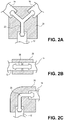
- FIGS. 2A-2E illustrates various different embodiments of a fluid management assembly 10.
- the connector 20 may take a number of different forms and configurations.
- the connector 20 may be a wye, tee, elbow, coupling, or connector.
- FIG. 2A illustrates a connector 20 in the form of a wye (or "Y").
- FIG. 2B illustrates the connector 20 in the form of a coupler.
- FIG. 2C illustrates a connector in the form of an elbow.
- FIG. 2D illustrates another embodiment of a connector 20 in the form of a manifold.
- FIG. 2E illustrates another embodiment of a connector 20 in the form of a reducer.
- the connector 20 is able to couple tubes having different internal diameters (ID).
- ID internal diameters
- Other configurations may also be used for the connector 20.
- the connector 20 may be a union member, or multi inlet/outlet member.
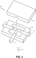
- FIG. 3 illustrates a mold 40 used in connection with the formation of the fluid management assembly 10.
- the mold 40 illustrated in FIG. 3 includes first and second halves 42, 44.
- a cavity 46 is formed in the mold as illustrated in FIG. 3 that is used to receive the polymer-based overmolding 30 in liquid form.
- the mold 40 should be transparent to UV radiation and stable during the curing process.
- the mold 40 is made from quartz glass or polymethyl methacrylate (PMMA).
- a UV light source 48 is also provided as seen in FIG. 3 .
- the UV light source 48 may be provided external to the mold 40 or, in other embodiments, may be integrated into a portion of the mold 40 itself.
- the UV light source 48 may include gas discharge lamps (microwave or electrode systems) or LED lamps.
- LED lamps may be preferred because they generate less heat and may result in molds 40 having a longer life.
- the molds 40 may be made using conventional mold-making processes.
- the molds 40 can also be made using three-dimensional printing technologies such that designs can be rapidly and cheaply turned into products.
- a method of forming a fluid management assembly 10 includes coupling first and second silicone tubing portions (e.g., 12, 14, 16) to a connector 20 having at least one inlet and at least one outlet and a lumen extending there between, wherein the at least one inlet is coupled to the first silicone tubing portion at a first interface and wherein the at least one outlet is coupled to the second silicone tubing portion at a second interface.
- the connector 20 is inserted into a cavity of a mold 40.
- the silicone tubing portions 12, 14, 16 may be connected to the connecter 20 after it has been inserted into the mold 40.
- a liquid silicone rubber is injected into the mold cavity 46 and surrounds the connector 20 and connected tubing portions 12, 14, 16. UV radiation from the UV light source 48 is applied to the liquid silicone rubber to cure the silicone. While this embodiment is described in the context of a UV-curable silicone, it should be understood that other UV-curable polymers are also contemplated.
- FIG. 4 illustrates another embodiment of a fluid management assembly 10.
- the overmolding 30 encapsulates an interior connector like the manifold of FIG. 2D that is connected to varying tubing segments.
- valves 50 are provided on the overmolding 30 and selectively engage or pinch portions of the interior connector to valve fluid to one or more particular tubing segments.
- the valves 50 may be manual bonnet-style valves or the valves may be automatically actuated valves (e.g., pneumatic or servo-based).
- the fluid management assembly 10 of FIG. 10 has particular robustness and can operate at high pressures.
- the fluid management assembly 10 is designed to be disposable. Systems that are disposable or incorporate disposable elements are advantageous because they avoid the need for cleaning-in-place (CIP) cleaning, sanitization, or re-sterilization.
- CIP cleaning-in-place
- a major advantage of the embodiments described herein is that the product contained within the system only contacts two components - the interior surface of the tubing 12, 14, 16 as well as the interior surface of the connector 20. The product does not contact any third substance such as a mandrel or flashing material left from some other component used during the manufacturing process.
- the fluid management assembly 10 is also scalable meaning that large diameter tubes can be used. Further, the fluid management assembly 10 is very robust and able to handle large pressures.
- a fluid management assembly may be made using a mandrel using one or more techniques described above, for example, as noted in U.S. Patent 6,290,265 , however the mandrel is used in conjunction with a UV-curable overmolding as described herein. In such an alternative embodiment, there is no need for a separate connector.
Landscapes
- Engineering & Computer Science (AREA)
- Mechanical Engineering (AREA)
- General Engineering & Computer Science (AREA)
- Health & Medical Sciences (AREA)
- Heart & Thoracic Surgery (AREA)
- Manufacturing & Machinery (AREA)
- Anesthesiology (AREA)
- Life Sciences & Earth Sciences (AREA)
- Animal Behavior & Ethology (AREA)
- General Health & Medical Sciences (AREA)
- Public Health (AREA)
- Veterinary Medicine (AREA)
- Hematology (AREA)
- Biomedical Technology (AREA)
- Pulmonology (AREA)
- Casting Or Compression Moulding Of Plastics Or The Like (AREA)
- Moulds For Moulding Plastics Or The Like (AREA)
Description
- The field of the invention generally relates to fluid management devices and, in particular, connectors or interfaces used therein. More specifically, the invention pertains to connectors or interfaces used by pharmaceutical and biological applications or other hygienic process industries involving silicone tubing or other conduits.
- Many commercial products are produced using chemical as well as biological processes. Pharmaceuticals, for example, are produced in commercial quantities using scaled-up reactors and other equipment. So-called biologics are drugs or other compounds that are produced or isolated from living entities such as cells or tissue. Biologics can be composed of proteins, nucleic acids, or complex combinations of these substances. They may even include living entities such as cells. In order to produce biologics on a commercial scale, sophisticated and expensive equipment is needed. In both pharmaceutical and biologics, for example, various processes need to occur before the final product is obtained. For example, in the case of biologics, cells may be grown in a growth chamber or the like and nutrients may need to be carefully modulated into the growth chamber. Waste products produced by cells may also have to be removed on a controlled basis from the fermentation chamber. As another example, biologic products produced by living cells or other organisms may need to be extracted and concentrated. This process may involve a variety of filtration and separation techniques.
- Because there are a number of individual processes required to be produce the final product, various reactants, solutions, and washes are often pumped or otherwise transported to various subsystems using conduits and associated valves. These systems may be quite cumbersome and organizationally complex due to the large numbers of conduits, valves, sensors, and the like that may be needed in such systems. Not only are these systems visually complex (e.g., resembling spaghetti) they also include many components that are required to sterilized between uses to avoid cross-contamination issues. Indeed, the case of drug and biologic preparation, the Federal Food and Drug Administration (FDA) is becoming increasingly strict on cleaning, sterilization or bio-burden reduction procedures that are required for drug and pharmaceutical preparations. This is particularly of a concern because many of these products are produced in batches which would require repeated cleaning, sterilization or bio-burden reduction activities on a variety of components.
- Some attempts have been made at incorporating various disposable elements into the system. For example, conduits or lines connecting various systems or elements have been made of silicone. Unfortunately, silicone tubing or conduits often have to be reinforced along their periphery to avoid the possibility of leakage through an aneurysm or the like that develops at the wall of the tubing. Reinforced silicone tubing is, however, rather expensive and is not as flexible as un-reinforced silicone.
- In addition, silicone tubing often connects to other connectors or junctions (e.g., Tees, Wyes, unions, elbows) as part of the overall system. Current interfaces between silicone tubing and various connectors are deficient in a number of respects. First, current interfaces are limited in the pressure that they can handle. For example, existing connections between silicone tubing and connectors can operate at pressures at or below about 2.07 bar (30 psi). There is a growing need to utilize higher pressures within systems because higher pressures (as well as larger tubing diameters) enables higher throughput. In addition, the interface between the silicone tubing and the connector often requires an external clamping member such as a zip tie which surrounds the junction between the silicone tubing and the inner connector. Unfortunately, the presence of these zip ties or other clamping members on the exterior tubing can lead to tears or breakages in the disposable gloves used by workers which jeopardizes the sterile environment in which these systems are typically used.
- Another disadvantage of current junctions and interfaces between silicone tubing and various devices is the fact that they introduce another material that contacts the pharmaceutical or biological component that is carried through the system. While plastics and silicone have known interactions with pharmaceutical and biological components, other materials have unknown or deleterious effects on the final product. This tertiary contact with the product may jeopardize the purity and sterility of the ultimate product. For example, connectors and junctions are sometimes created using an internal mandrel. During the manufacturing process, the use of the mandrel produces flash which may have to be manually removed prior to final assembly and use. Inevitably, however, some flash may remain which can clog or otherwise disrupt the process. It also introduces a variable in the form of the overmolding or joining silicone that is now a product contact material that needs to be monitored and qualified for the manufacturer's validation documentation.
-
U.S. Patent No. 5,447,341 illustrates a molded hose branch of rubber that is formed by slipping completely vulcanized rubber hose lengths with ends onto the free ends of a plastic tubing branching piece. The assembly is placed into a mold and a thermoplastic material such as a blended mixture of polyproplylene and EPDM is injected molded around the assembly so as to join the thermoplastic material to the rubber hose lengths. The problem with such a construction in connection with systems that rely on silicone, in conventional silicone molding processes, the temperature at which silicone cures would cause the inner plastic branching piece to melt. Standard platinum cured silicone may require extended temperature of around 180 °C to cross-link silicone. These high temperatures would melt or otherwise destroy the underlying plastic branching piece. -
U.S. Patent No. 6,290,265 discloses a tubing and connector assembly that includes a multi-lumen connector having at least three flexible tubes molded onto the connector. The process of making the connector and tubing assembly includes forming a first part of the connector with two tubes molded therein and then removing an internal mold member prior to molding the final connector portion and third tube in place. As noted above, in this method, an internal mandrel-type structure is used as the method uses an inner mold member and mold insert. -
U.S. Patent No. 6,432,345 illustrates a single-step method of manufacturing a silicone tube manifold. The method forms, in a single step, a silicone manifold interconnecting a plurality of silicone tubes. The method is performed by providing a silicone insert piece having a network of interior channels dimensioned the same as the silicone tube interiors. Solid non-silicone plugs are inserted into the insert piece and the ends of the silicone tubes and the resulting assembly is placed in a mold cavity. Liquid silicone is added to the mold cavity and is then heated and cured to form the desired manifold interconnecting the tubes. The manifold is then removed from the mold and a source of pressurized air is used to blow out the plugs. -
U.S. Patent No. 8,424,923 illustrates a fluid transfer assembly for transporting medicinal substances. The fluid transfer assembly includes flexible tubes and a manifold each comprising silicone. The manifold has an inner protrusion and connector portions having inner walls. Free ends of the tubes are inserted into complementary configured inner walls of the connector portions until each of the free ends abut the inner protrusion, which creates a continuous uninterrupted passageway between the inner bores of the tubes through the manifold. This patent discloses the formation of an outer capsule by using silicone rubber that is introduced into a molding assembly. -
WO 2007/048072 shows a fluid transfer assembly comprising a manifold, flexible tubes and an outer capsule made from silicone based materials. - The invention as defined in
claim 1 and 9 aims at overcoming the drawbacks of the prior art. The subject-matter ofclaim 1 defines a fluid management assembly according to the invention. The subject-matter of claim 9 defines a method of forming a fluid management assembly according to the invention. -
-
FIG. 1 illustrates a fluid management assembly according to one embodiment. -
FIG. 2A illustrates a fluid management assembly with a connector formed as a wye. -
FIG. 2B illustrates a fluid management assembly with a connector formed as a connector. -
FIG. 2C illustrates a fluid management assembly with a connector formed as an elbow. -
FIG. 2D illustrates another embodiment of a connector in the form of a manifold. -
FIG. 2E illustrates another embodiment of a connector in the form of a reducer. -
FIG. 3 illustrates a mold containing a connector and tubing segments ready to receive the liquid polymer. -
FIG. 4 illustrates a fluid management assembly according to another embodiment. -
FIG. 1 illustrates afluid management assembly 10 according to one embodiment. The fluid management assembly as illustrated inFIG. 1 includes afirst tubing segment 12, asecond tubing segment 14, and athird tubing segment 16. Eachtubing segment tubing segments tubing segments tubing segments connector 20. Theconnector 20 illustrated inFIG. 1 includes ends 22, 24, and 26. The ends 22, 24, 26 are preferably barbed ends as illustrated although in other embodiments theends tubing segment connector 20. - In the embodiment of
FIG. 1 , one tubing segment (e.g., segment 12) may serve as an inlet while the remainingtubing segments connector 20 are contemplated. In all the embodiments, there is at least one inlet and at least one outlet on theconnector 20. Still referring toFIG. 1 , clamps 28 are illustrated surrounding thetubing segments tubing segments ends clamps 28 are optional and may increase the robustness of thefluid management assembly 10 enabling the same to operate at higher pressures. Theclamps 28 may take any number of forms. For example, theclamps 28 may include hose clamps or zip ties commonly used in fluid applications. - The
connector 20 may be made from a number of polymer materials. For example, theconnector 20 may be made from a plastic material. Plastic materials include standard thermoplastics and polyolefins such as polyethylene (PE) and polypropylene (PP). Theconnector 20 may also be formed from fluoropolymers such as polyvinylidene fluoride (PVDF) or Perfluoroalkoxy (PFA), Polytetrafluoroethylene (PTFE), Polycarbonate (which may be more thermally resistant) and the like. Typically, theconnector 20 is made from a polymer material that would be compromised upon exposure to high thermal temperatures like those experienced in conventional thermal curing processes. - Still referring to
FIG. 1 , thefluid management assembly 10 includes a polymer-basedovermolding 30. The polymer-basedovermolding 30 as explained in more detail below is a solid section that becomes solid after exposure to ultraviolet (UV) radiation during a curing process. Theovermolding 30 covers the entirety of theconnector 20 as well as the interface formed betweentubing segments overmolding 30 adds additional strength to the respective interfaces formed between thetubing segments ends fluid management assembly 10 to be very robust and can operate at very high operating pressures. For example, typical connectors are believed to operate at maximum pressures of around 1.72 - 2.07 bar (25-30 psi). However, in thefluid management assembly 10 is able to operate at much higher pressures - e.g., above 3.45 bar 50 (psi) or6.89 bar (100 psi). The presence of theoptional clamps 28 can be used for applications requiring particularly high pressures. - In one aspect of the invention, the polymer-based
overmolding 30 is silicone based. For example, SILOPREN available from Momentive Performance Materials Inc. (Albany, NY) is a UV cured Liquid Silicone Rubber (LSR) that may be used as theovermolding 30. SILOPREN is a two-component LSR what uses a mixing ratio of 100:2. Another example of a UV cured silicone is ADDISIL available from Momentive Performance Materials Inc. (Albany, NY) which offers high cure speed at room temperatures. ADDISIL silicone rubber is a two component solution that uses a mixing ratio of 100:0.5 (Rubber Base:Catalyst). The benefits of using a UVcurable overmolding 30 are numerous. First, there is no heating of the materials as is required in conventional silicone curing techniques. Thus, theovermolding 30 may be formed at substantially room temperatures. If the polymer basedconnector 20 described herein were to be overmolded with conventional thermally-cured silicone, theconnector 20 itself would melt, deform, or otherwise fail during the curing process. Here, using the UV curing process, theconnector 20 remains unaffected by the curing process. Because no heating is required, the process also has low energy consumption. Further, the UV curing process uses less equipment and can increase throughput as heating up and cool-down tend to consume a considerable amount of time. Another example of a UV curable silicone is the SEMICOSIL UV product made by Wacker Chemie AG (Munich, Germany). - Standard liquid silicone rubbers are processed in molds generally at temperatures between 180 and 200°C. UV-cured LSR parts can be made with transparent molds cured by UV light as explained herein. UV curing typically occurs at ambient or slightly above ambient temperatures (e.g., 25-40°C). For thick parts, UV curing is advantageous because the product may cross-link much more quickly than with thermal curing because the low thermal conductivity of the silicone rubber is not a factor. Another advantage of UV curing is that the curing is initiated when the light is first turned on rather than on first contact with the heated mold. This difference eliminates the problem of silicone rubber scorching. Related to this, the liquid silicone (or other polymer) can be pumped into the mold relatively slowly and at low pressures.
-
FIGS. 2A-2E illustrates various different embodiments of afluid management assembly 10. Theconnector 20 may take a number of different forms and configurations. For example, theconnector 20 may be a wye, tee, elbow, coupling, or connector.FIG. 2A illustrates aconnector 20 in the form of a wye (or "Y").FIG. 2B illustrates theconnector 20 in the form of a coupler.FIG. 2C illustrates a connector in the form of an elbow.FIG. 2D illustrates another embodiment of aconnector 20 in the form of a manifold.FIG. 2E illustrates another embodiment of aconnector 20 in the form of a reducer. Here, theconnector 20 is able to couple tubes having different internal diameters (ID). Other configurations may also be used for theconnector 20. For example, theconnector 20 may be a union member, or multi inlet/outlet member. Theconnector 20, in a general sense, includes at least one inlet and at least one outlet. -
FIG. 3 illustrates amold 40 used in connection with the formation of thefluid management assembly 10. Themold 40 illustrated inFIG. 3 includes first andsecond halves cavity 46 is formed in the mold as illustrated inFIG. 3 that is used to receive the polymer-basedovermolding 30 in liquid form. Themold 40 should be transparent to UV radiation and stable during the curing process. In one aspect, themold 40 is made from quartz glass or polymethyl methacrylate (PMMA). AUV light source 48 is also provided as seen inFIG. 3 . TheUV light source 48 may be provided external to themold 40 or, in other embodiments, may be integrated into a portion of themold 40 itself. TheUV light source 48 may include gas discharge lamps (microwave or electrode systems) or LED lamps. LED lamps may be preferred because they generate less heat and may result inmolds 40 having a longer life. Themolds 40 may be made using conventional mold-making processes. Themolds 40 can also be made using three-dimensional printing technologies such that designs can be rapidly and cheaply turned into products. - In one aspect of the invention, a method of forming a
fluid management assembly 10 includes coupling first and second silicone tubing portions (e.g., 12, 14, 16) to aconnector 20 having at least one inlet and at least one outlet and a lumen extending there between, wherein the at least one inlet is coupled to the first silicone tubing portion at a first interface and wherein the at least one outlet is coupled to the second silicone tubing portion at a second interface. Theconnector 20 is inserted into a cavity of amold 40. Alternatively, thesilicone tubing portions connecter 20 after it has been inserted into themold 40. A liquid silicone rubber is injected into themold cavity 46 and surrounds theconnector 20 and connectedtubing portions light source 48 is applied to the liquid silicone rubber to cure the silicone. While this embodiment is described in the context of a UV-curable silicone, it should be understood that other UV-curable polymers are also contemplated. -
FIG. 4 illustrates another embodiment of afluid management assembly 10. In this embodiment, theovermolding 30 encapsulates an interior connector like the manifold ofFIG. 2D that is connected to varying tubing segments. In this embodiment,valves 50 are provided on theovermolding 30 and selectively engage or pinch portions of the interior connector to valve fluid to one or more particular tubing segments. Thevalves 50 may be manual bonnet-style valves or the valves may be automatically actuated valves (e.g., pneumatic or servo-based). Thefluid management assembly 10 of FIG. 10 has particular robustness and can operate at high pressures. - It should be understood that the
fluid management assembly 10 is designed to be disposable. Systems that are disposable or incorporate disposable elements are advantageous because they avoid the need for cleaning-in-place (CIP) cleaning, sanitization, or re-sterilization. A major advantage of the embodiments described herein is that the product contained within the system only contacts two components - the interior surface of thetubing connector 20. The product does not contact any third substance such as a mandrel or flashing material left from some other component used during the manufacturing process. Thefluid management assembly 10 is also scalable meaning that large diameter tubes can be used. Further, thefluid management assembly 10 is very robust and able to handle large pressures. - In another alternative embodiment of the invention, a fluid management assembly may be made using a mandrel using one or more techniques described above, for example, as noted in
U.S. Patent 6,290,265 , however the mandrel is used in conjunction with a UV-curable overmolding as described herein. In such an alternative embodiment, there is no need for a separate connector. - While embodiments of the present invention have been shown and described, various modifications may be made without departing from the scope of the present invention. The invention, therefore, should not be limited, except to the following claims.
Claims (12)
- A fluid management assembly (10) comprising:a connector (20) having at least one inlet and at least one outlet and a lumen extending there between, wherein the connector (20) comprises a plastic material comprising one of polyethylene (PE), polypropylene (PP), polyvinylidene fluoride (PVDF), perfluoroalkoxy (PFA), polytetrafluoroethylene (PTFE), orpolycarbonate;a first silicone tubing (12) connected to the at least one inlet at a first interface; a second silicone tubing (14, 16) connected to the at least one outlet at a second interface;a silicone overmolding (30) surrounding the connector (20), the first interface, and the second interface, wherein the silicone overmolding (30) comprises a UV-cured silicone cured at ambient or slightly above temperatures.
- The fluid management assembly (10) of claim 1, wherein the connector (20) comprises a Tee connector, a Wye conector, a union, a coupler, an elbow, a reducer.
- The fluid management assembly (10) of claim 1, further comprising a clamp (28) surrounding the first silicone tubing at the first interface.
- The fluid management assembly (10) of claim 1, further comprising a clamp (28) surrounding the second silicone tubing at the second interface.
- The fluid management assembly (10) of claim 1, wherein the burst pressure of the assembly exceeds 3.45 bar (50 psi).
- The fluid management assembly (10) of claim 1, wherein the burst pressure of the assembly exceeds 6.89 bar (100 psi).
- The fluid management assembly (10) of claim 1, wherein the at least one inlet and the at least one outlet comprise barbed ends (22, 24, 26) formed about the exterior of the connector.
- The fluid management assembly of claim 1, further comprising valves disposed on the silicon overmolding and configured to selectively engage or pinch portions of the connector.
- A method of forming a fluid management assembly (10) comprising:coupling first and second silicone tubing portions to a plastic connector comprising one of polyethylene (PE), polypropylene (PP), polyvinylidene fluoride (PVDF), perfluoroalkoxy (PFA), polytetrafluoroethylene (PTFE), orpolycarbonate and having at least one inlet and at least one outlet and a lumen extending there between, wherein the at least one inlet is coupled to the first silicone tubing portion at a first interface and wherein the at least one outlet is coupled to the second silicone tubing portion at a second interface;inserting the connector (20) into a cavity of a mold (40);injecting a liquid silicone rubber into the mold cavity cured at ambient or slightly above temperatures; andapplying UV radiation to the liquid silicone rubber through the mold to cure the silicone.
- The method of claim 9, wherein the connector (20) is inserted into the cavity of the mold (40) prior to coupling the first and second silicone tubing portions to the plastic material connector (20).
- The method of claim 9, wherein the connector (20) is inserted into the cavity of the mold (40) after coupling the first and second silicone tubing portions to the plastic material connector (20).
- The method of claim9, further comprising securing a clamp (28) around the first silicone tubing portion at the first interface or a clamp around the second silicone tubing portion at the second interface.
Applications Claiming Priority (2)
| Application Number | Priority Date | Filing Date | Title |
|---|---|---|---|
| US201361871752P | 2013-08-29 | 2013-08-29 | |
| PCT/US2014/052383 WO2015031207A1 (en) | 2013-08-29 | 2014-08-22 | Method and device for overmolding uv-curable material over polymer inserts |
Publications (3)
| Publication Number | Publication Date |
|---|---|
| EP3038812A1 EP3038812A1 (en) | 2016-07-06 |
| EP3038812A4 EP3038812A4 (en) | 2017-03-29 |
| EP3038812B1 true EP3038812B1 (en) | 2019-11-20 |
Family
ID=52587233
Family Applications (1)
| Application Number | Title | Priority Date | Filing Date |
|---|---|---|---|
| EP14838968.7A Active EP3038812B1 (en) | 2013-08-29 | 2014-08-22 | Method and device for overmolding uv-curable material over polymer inserts |
Country Status (6)
| Country | Link |
|---|---|
| US (1) | US20160200038A1 (en) |
| EP (1) | EP3038812B1 (en) |
| KR (1) | KR20160048871A (en) |
| SG (1) | SG11201601255WA (en) |
| TW (1) | TWI595182B (en) |
| WO (1) | WO2015031207A1 (en) |
Cited By (1)
| Publication number | Priority date | Publication date | Assignee | Title |
|---|---|---|---|---|
| DE102023206594A1 (en) | 2023-07-11 | 2025-01-16 | Raumedic Ag | Device for connecting two silicone hose sections in a pharmaceutical media transfer process |
Families Citing this family (19)
| Publication number | Priority date | Publication date | Assignee | Title |
|---|---|---|---|---|
| BR112013003354A2 (en) * | 2010-08-13 | 2019-09-24 | Petterson Bart | aluminum-based solderless hvac system |
| US10240704B2 (en) * | 2014-12-31 | 2019-03-26 | Saint-Gobain Performance Plastics Corporation | Molded fluid transfer assemblies having increased working pressures and burst pressures |
| US11357966B2 (en) * | 2015-04-23 | 2022-06-14 | B. Braun Medical Inc. | Compounding device, system, kit, software, and method |
| US11020921B2 (en) * | 2016-10-03 | 2021-06-01 | The Goodyear Tire & Rubber Company | Connecting member for an air maintenance tire and method of forming the same |
| SG11201906632WA (en) | 2017-01-31 | 2019-08-27 | Alphinity Llc | Bioprocess vessels with integrated pump |
| DE202017101274U1 (en) * | 2017-03-06 | 2017-03-24 | TI Automotive (Fuldabrück) GmbH | Physical connection |
| US10649472B2 (en) * | 2017-07-10 | 2020-05-12 | Tse Industries, Inc. | Tubing system |
| EP3837003A4 (en) * | 2018-08-13 | 2022-05-11 | Invetech, Inc. | FUNCTIONALIZED UNITARY MOLDED MANIFOLDS FOR CLOSED FLUID HANDLING SYSTEMS |
| EP3993991B1 (en) | 2019-07-01 | 2025-05-21 | Saint-Gobain Performance Plastics Corporation | Profile connection |
| KR102823017B1 (en) * | 2019-12-27 | 2025-06-23 | 생-고뱅 퍼포먼스 플라스틱스 코포레이션 | Link profile |
| CN111202593B (en) * | 2020-03-20 | 2025-04-04 | 上海加奇生物科技苏州有限公司 | Medical device handles |
| KR102927869B1 (en) | 2020-03-20 | 2026-02-20 | 생-고뱅 퍼포먼스 플라스틱스 코포레이션 | Sterile sealing device |
| EP4171920A4 (en) | 2020-06-19 | 2024-11-06 | Saint-Gobain Performance Plastics Corporation | COMPOSITE ARTICLE AND METHOD OF FORMING COMPOSITE ARTICLE |
| US20240093815A1 (en) * | 2020-11-10 | 2024-03-21 | Composite Fluid Transfer LLC | Universal high-pressure fittings for composite pipes |
| WO2022103508A1 (en) * | 2020-11-10 | 2022-05-19 | Composite Fluid Transfer LLC | Universal high-pressure fittings for composite pipes |
| DE102022200748A1 (en) * | 2022-01-24 | 2023-07-27 | Raumedic Ag | Method for connecting two silicone hose sections and pharmaceutical media transfer method with such a connecting method and device for carrying out the method |
| KR20240169056A (en) | 2022-03-31 | 2024-12-02 | 엔테그리스, 아이엔씨. | Overmolding specialty tooling and methods for manufacturing flexible substrate components |
| US20240351847A1 (en) * | 2023-04-21 | 2024-10-24 | Sartorius Stedim North America Ins. | Tube holding apparatuses for filling of multiple containers and methods for using the same |
| DE102023205431A1 (en) | 2023-06-12 | 2024-12-12 | Raumedic Ag | Device for connecting two silicone hose sections in a pharmaceutical media transfer process |
Family Cites Families (13)
| Publication number | Priority date | Publication date | Assignee | Title |
|---|---|---|---|---|
| SE455470B (en) * | 1981-06-23 | 1988-07-18 | Terumo Corp | CONNECTING TWO HOSE FOR MEDICAL, THERAPEUTICAL USE HOSE |
| US5447341A (en) | 1988-06-13 | 1995-09-05 | Metzeler Automotive Profiles Gmbh | Molder rubber hose branch |
| US5411300A (en) * | 1993-03-16 | 1995-05-02 | Toyoda Gosei Co., Ltd. | Hose connecting assembly |
| US6290265B1 (en) | 1997-08-11 | 2001-09-18 | Saint-Gobain Performance Plastics Corporation | Tubing and connector assembly and method and molding |
| US6432345B1 (en) | 1999-12-29 | 2002-08-13 | Truseal Usa, Inc. | Single-step method of manufacturing a silicone tube manifold |
| US8005624B1 (en) * | 2004-04-26 | 2011-08-23 | Starr Life Sciences Corp. | Medical devices and techniques for rodent and small mammalian based research |
| EP2383502B1 (en) | 2005-10-21 | 2013-11-20 | Dow Corning Corporation | Fluid transfer assembly |
| US8292875B2 (en) * | 2006-09-12 | 2012-10-23 | Clay Kennard | Fluid delivery device |
| US20110276033A1 (en) * | 2008-12-30 | 2011-11-10 | Cook Medical Technologies Llc | Wire guide and method of making same |
| SG191998A1 (en) * | 2011-03-03 | 2013-08-30 | Emd Millipore Corp | Tubing and connector and method making the same |
| WO2012170008A1 (en) * | 2011-06-06 | 2012-12-13 | Abb Research Ltd. | Method of producing shaped articles from a uv-curable silicone rubber composition |
| US20130043676A1 (en) * | 2011-08-16 | 2013-02-21 | Newage Industries, Inc. | Overmolded seal for barbed tubing connection |
| US9901725B2 (en) * | 2012-10-01 | 2018-02-27 | Bayer Healthcare Llc | Overmolded medical connector tubing and method |
-
2014
- 2014-08-22 SG SG11201601255WA patent/SG11201601255WA/en unknown
- 2014-08-22 EP EP14838968.7A patent/EP3038812B1/en active Active
- 2014-08-22 WO PCT/US2014/052383 patent/WO2015031207A1/en not_active Ceased
- 2014-08-22 US US14/912,693 patent/US20160200038A1/en not_active Abandoned
- 2014-08-22 KR KR1020167007799A patent/KR20160048871A/en not_active Withdrawn
- 2014-08-29 TW TW103129915A patent/TWI595182B/en not_active IP Right Cessation
Non-Patent Citations (1)
| Title |
|---|
| None * |
Cited By (1)
| Publication number | Priority date | Publication date | Assignee | Title |
|---|---|---|---|---|
| DE102023206594A1 (en) | 2023-07-11 | 2025-01-16 | Raumedic Ag | Device for connecting two silicone hose sections in a pharmaceutical media transfer process |
Also Published As
| Publication number | Publication date |
|---|---|
| SG11201601255WA (en) | 2016-03-30 |
| US20160200038A1 (en) | 2016-07-14 |
| TWI595182B (en) | 2017-08-11 |
| EP3038812A1 (en) | 2016-07-06 |
| KR20160048871A (en) | 2016-05-04 |
| WO2015031207A1 (en) | 2015-03-05 |
| TW201510402A (en) | 2015-03-16 |
| EP3038812A4 (en) | 2017-03-29 |
Similar Documents
| Publication | Publication Date | Title |
|---|---|---|
| US20160200038A1 (en) | Method and device for overmolding uv-curable material over polymer inserts | |
| JP7144877B2 (en) | Valve assembly with directional flow path | |
| CN107110412B (en) | Molded fluid delivery assemblies with increased working and burst pressures | |
| EP3063506B1 (en) | Fluid monitoring device with disposable inner liner with sensor integration | |
| US12372156B2 (en) | Encapsulated system for pressurized fluid processes | |
| US12304116B2 (en) | Fluid transfer assembly, a fluid transfer system, and a related method | |
| US11530772B2 (en) | Fluid plug for sterile processes and methods of using the same | |
| AU2019321409A1 (en) | Functionalized unitary molded manifolds for closed fluid handling systems | |
| CN118414240A (en) | Pipe coupling moldings and systems and related methods |
Legal Events
| Date | Code | Title | Description |
|---|---|---|---|
| PUAI | Public reference made under article 153(3) epc to a published international application that has entered the european phase |
Free format text: ORIGINAL CODE: 0009012 |
|
| 17P | Request for examination filed |
Effective date: 20160229 |
|
| AK | Designated contracting states |
Kind code of ref document: A1 Designated state(s): AL AT BE BG CH CY CZ DE DK EE ES FI FR GB GR HR HU IE IS IT LI LT LU LV MC MK MT NL NO PL PT RO RS SE SI SK SM TR |
|
| AX | Request for extension of the european patent |
Extension state: BA ME |
|
| RIN1 | Information on inventor provided before grant (corrected) |
Inventor name: RICHARDS, DEAN Inventor name: CATES, STEVEN V. Inventor name: GAGNE, MICHAEL C. |
|
| DAX | Request for extension of the european patent (deleted) | ||
| A4 | Supplementary search report drawn up and despatched |
Effective date: 20170227 |
|
| RIC1 | Information provided on ipc code assigned before grant |
Ipc: B29C 65/70 20060101AFI20170221BHEP Ipc: B29C 45/14 20060101ALI20170221BHEP |
|
| STAA | Information on the status of an ep patent application or granted ep patent |
Free format text: STATUS: EXAMINATION IS IN PROGRESS |
|
| 17Q | First examination report despatched |
Effective date: 20180515 |
|
| GRAP | Despatch of communication of intention to grant a patent |
Free format text: ORIGINAL CODE: EPIDOSNIGR1 |
|
| STAA | Information on the status of an ep patent application or granted ep patent |
Free format text: STATUS: GRANT OF PATENT IS INTENDED |
|
| RIC1 | Information provided on ipc code assigned before grant |
Ipc: A61M 39/10 20060101ALI20190429BHEP Ipc: B29C 45/14 20060101ALI20190429BHEP Ipc: B29C 65/70 20060101AFI20190429BHEP Ipc: B29K 83/00 20060101ALN20190429BHEP Ipc: A61M 39/12 20060101ALI20190429BHEP Ipc: F16L 47/32 20060101ALI20190429BHEP Ipc: B29L 31/24 20060101ALN20190429BHEP Ipc: B29K 105/24 20060101ALN20190429BHEP Ipc: F16L 33/34 20060101ALI20190429BHEP Ipc: B29C 65/00 20060101ALI20190429BHEP |
|
| INTG | Intention to grant announced |
Effective date: 20190523 |
|
| GRAS | Grant fee paid |
Free format text: ORIGINAL CODE: EPIDOSNIGR3 |
|
| GRAA | (expected) grant |
Free format text: ORIGINAL CODE: 0009210 |
|
| STAA | Information on the status of an ep patent application or granted ep patent |
Free format text: STATUS: THE PATENT HAS BEEN GRANTED |
|
| AK | Designated contracting states |
Kind code of ref document: B1 Designated state(s): AL AT BE BG CH CY CZ DE DK EE ES FI FR GB GR HR HU IE IS IT LI LT LU LV MC MK MT NL NO PL PT RO RS SE SI SK SM TR |
|
| REG | Reference to a national code |
Ref country code: GB Ref legal event code: FG4D |
|
| REG | Reference to a national code |
Ref country code: CH Ref legal event code: EP |
|
| REG | Reference to a national code |
Ref country code: IE Ref legal event code: FG4D |
|
| REG | Reference to a national code |
Ref country code: DE Ref legal event code: R096 Ref document number: 602014057242 Country of ref document: DE |
|
| REG | Reference to a national code |
Ref country code: AT Ref legal event code: REF Ref document number: 1203710 Country of ref document: AT Kind code of ref document: T Effective date: 20191215 |
|
| REG | Reference to a national code |
Ref country code: CH Ref legal event code: NV Representative=s name: DR. ALEXANDER MILLER, LL.M. RECHTSANWALT (D), CH |
|
| REG | Reference to a national code |
Ref country code: NL Ref legal event code: MP Effective date: 20191120 |
|
| REG | Reference to a national code |
Ref country code: LT Ref legal event code: MG4D |
|
| PG25 | Lapsed in a contracting state [announced via postgrant information from national office to epo] |
Ref country code: FI Free format text: LAPSE BECAUSE OF FAILURE TO SUBMIT A TRANSLATION OF THE DESCRIPTION OR TO PAY THE FEE WITHIN THE PRESCRIBED TIME-LIMIT Effective date: 20191120 Ref country code: SE Free format text: LAPSE BECAUSE OF FAILURE TO SUBMIT A TRANSLATION OF THE DESCRIPTION OR TO PAY THE FEE WITHIN THE PRESCRIBED TIME-LIMIT Effective date: 20191120 Ref country code: NL Free format text: LAPSE BECAUSE OF FAILURE TO SUBMIT A TRANSLATION OF THE DESCRIPTION OR TO PAY THE FEE WITHIN THE PRESCRIBED TIME-LIMIT Effective date: 20191120 Ref country code: BG Free format text: LAPSE BECAUSE OF FAILURE TO SUBMIT A TRANSLATION OF THE DESCRIPTION OR TO PAY THE FEE WITHIN THE PRESCRIBED TIME-LIMIT Effective date: 20200220 Ref country code: LT Free format text: LAPSE BECAUSE OF FAILURE TO SUBMIT A TRANSLATION OF THE DESCRIPTION OR TO PAY THE FEE WITHIN THE PRESCRIBED TIME-LIMIT Effective date: 20191120 Ref country code: GR Free format text: LAPSE BECAUSE OF FAILURE TO SUBMIT A TRANSLATION OF THE DESCRIPTION OR TO PAY THE FEE WITHIN THE PRESCRIBED TIME-LIMIT Effective date: 20200221 Ref country code: NO Free format text: LAPSE BECAUSE OF FAILURE TO SUBMIT A TRANSLATION OF THE DESCRIPTION OR TO PAY THE FEE WITHIN THE PRESCRIBED TIME-LIMIT Effective date: 20200220 Ref country code: LV Free format text: LAPSE BECAUSE OF FAILURE TO SUBMIT A TRANSLATION OF THE DESCRIPTION OR TO PAY THE FEE WITHIN THE PRESCRIBED TIME-LIMIT Effective date: 20191120 |
|
| PG25 | Lapsed in a contracting state [announced via postgrant information from national office to epo] |
Ref country code: IS Free format text: LAPSE BECAUSE OF FAILURE TO SUBMIT A TRANSLATION OF THE DESCRIPTION OR TO PAY THE FEE WITHIN THE PRESCRIBED TIME-LIMIT Effective date: 20200320 Ref country code: HR Free format text: LAPSE BECAUSE OF FAILURE TO SUBMIT A TRANSLATION OF THE DESCRIPTION OR TO PAY THE FEE WITHIN THE PRESCRIBED TIME-LIMIT Effective date: 20191120 Ref country code: RS Free format text: LAPSE BECAUSE OF FAILURE TO SUBMIT A TRANSLATION OF THE DESCRIPTION OR TO PAY THE FEE WITHIN THE PRESCRIBED TIME-LIMIT Effective date: 20191120 |
|
| PG25 | Lapsed in a contracting state [announced via postgrant information from national office to epo] |
Ref country code: AL Free format text: LAPSE BECAUSE OF FAILURE TO SUBMIT A TRANSLATION OF THE DESCRIPTION OR TO PAY THE FEE WITHIN THE PRESCRIBED TIME-LIMIT Effective date: 20191120 |
|
| PG25 | Lapsed in a contracting state [announced via postgrant information from national office to epo] |
Ref country code: ES Free format text: LAPSE BECAUSE OF FAILURE TO SUBMIT A TRANSLATION OF THE DESCRIPTION OR TO PAY THE FEE WITHIN THE PRESCRIBED TIME-LIMIT Effective date: 20191120 Ref country code: RO Free format text: LAPSE BECAUSE OF FAILURE TO SUBMIT A TRANSLATION OF THE DESCRIPTION OR TO PAY THE FEE WITHIN THE PRESCRIBED TIME-LIMIT Effective date: 20191120 Ref country code: CZ Free format text: LAPSE BECAUSE OF FAILURE TO SUBMIT A TRANSLATION OF THE DESCRIPTION OR TO PAY THE FEE WITHIN THE PRESCRIBED TIME-LIMIT Effective date: 20191120 Ref country code: DK Free format text: LAPSE BECAUSE OF FAILURE TO SUBMIT A TRANSLATION OF THE DESCRIPTION OR TO PAY THE FEE WITHIN THE PRESCRIBED TIME-LIMIT Effective date: 20191120 Ref country code: EE Free format text: LAPSE BECAUSE OF FAILURE TO SUBMIT A TRANSLATION OF THE DESCRIPTION OR TO PAY THE FEE WITHIN THE PRESCRIBED TIME-LIMIT Effective date: 20191120 Ref country code: PT Free format text: LAPSE BECAUSE OF FAILURE TO SUBMIT A TRANSLATION OF THE DESCRIPTION OR TO PAY THE FEE WITHIN THE PRESCRIBED TIME-LIMIT Effective date: 20200412 |
|
| REG | Reference to a national code |
Ref country code: AT Ref legal event code: MK05 Ref document number: 1203710 Country of ref document: AT Kind code of ref document: T Effective date: 20191120 |
|
| REG | Reference to a national code |
Ref country code: DE Ref legal event code: R097 Ref document number: 602014057242 Country of ref document: DE |
|
| PG25 | Lapsed in a contracting state [announced via postgrant information from national office to epo] |
Ref country code: SK Free format text: LAPSE BECAUSE OF FAILURE TO SUBMIT A TRANSLATION OF THE DESCRIPTION OR TO PAY THE FEE WITHIN THE PRESCRIBED TIME-LIMIT Effective date: 20191120 Ref country code: SM Free format text: LAPSE BECAUSE OF FAILURE TO SUBMIT A TRANSLATION OF THE DESCRIPTION OR TO PAY THE FEE WITHIN THE PRESCRIBED TIME-LIMIT Effective date: 20191120 |
|
| PLBE | No opposition filed within time limit |
Free format text: ORIGINAL CODE: 0009261 |
|
| STAA | Information on the status of an ep patent application or granted ep patent |
Free format text: STATUS: NO OPPOSITION FILED WITHIN TIME LIMIT |
|
| 26N | No opposition filed |
Effective date: 20200821 |
|
| PG25 | Lapsed in a contracting state [announced via postgrant information from national office to epo] |
Ref country code: PL Free format text: LAPSE BECAUSE OF FAILURE TO SUBMIT A TRANSLATION OF THE DESCRIPTION OR TO PAY THE FEE WITHIN THE PRESCRIBED TIME-LIMIT Effective date: 20191120 Ref country code: AT Free format text: LAPSE BECAUSE OF FAILURE TO SUBMIT A TRANSLATION OF THE DESCRIPTION OR TO PAY THE FEE WITHIN THE PRESCRIBED TIME-LIMIT Effective date: 20191120 Ref country code: SI Free format text: LAPSE BECAUSE OF FAILURE TO SUBMIT A TRANSLATION OF THE DESCRIPTION OR TO PAY THE FEE WITHIN THE PRESCRIBED TIME-LIMIT Effective date: 20191120 |
|
| PG25 | Lapsed in a contracting state [announced via postgrant information from national office to epo] |
Ref country code: IT Free format text: LAPSE BECAUSE OF FAILURE TO SUBMIT A TRANSLATION OF THE DESCRIPTION OR TO PAY THE FEE WITHIN THE PRESCRIBED TIME-LIMIT Effective date: 20191120 |
|
| PGFP | Annual fee paid to national office [announced via postgrant information from national office to epo] |
Ref country code: LU Payment date: 20210810 Year of fee payment: 8 |
|
| PGFP | Annual fee paid to national office [announced via postgrant information from national office to epo] |
Ref country code: MC Payment date: 20210729 Year of fee payment: 8 |
|
| PGFP | Annual fee paid to national office [announced via postgrant information from national office to epo] |
Ref country code: MT Payment date: 20210819 Year of fee payment: 8 |
|
| PG25 | Lapsed in a contracting state [announced via postgrant information from national office to epo] |
Ref country code: TR Free format text: LAPSE BECAUSE OF FAILURE TO SUBMIT A TRANSLATION OF THE DESCRIPTION OR TO PAY THE FEE WITHIN THE PRESCRIBED TIME-LIMIT Effective date: 20191120 Ref country code: CY Free format text: LAPSE BECAUSE OF FAILURE TO SUBMIT A TRANSLATION OF THE DESCRIPTION OR TO PAY THE FEE WITHIN THE PRESCRIBED TIME-LIMIT Effective date: 20191120 |
|
| PG25 | Lapsed in a contracting state [announced via postgrant information from national office to epo] |
Ref country code: MK Free format text: LAPSE BECAUSE OF FAILURE TO SUBMIT A TRANSLATION OF THE DESCRIPTION OR TO PAY THE FEE WITHIN THE PRESCRIBED TIME-LIMIT Effective date: 20191120 |
|
| PGFP | Annual fee paid to national office [announced via postgrant information from national office to epo] |
Ref country code: IE Payment date: 20220609 Year of fee payment: 9 Ref country code: GB Payment date: 20220630 Year of fee payment: 9 |
|
| PGFP | Annual fee paid to national office [announced via postgrant information from national office to epo] |
Ref country code: DE Payment date: 20220608 Year of fee payment: 9 |
|
| PGFP | Annual fee paid to national office [announced via postgrant information from national office to epo] |
Ref country code: FR Payment date: 20220709 Year of fee payment: 9 Ref country code: BE Payment date: 20220718 Year of fee payment: 9 |
|
| PGFP | Annual fee paid to national office [announced via postgrant information from national office to epo] |
Ref country code: CH Payment date: 20220901 Year of fee payment: 9 |
|
| PG25 | Lapsed in a contracting state [announced via postgrant information from national office to epo] |
Ref country code: MC Free format text: LAPSE BECAUSE OF NON-PAYMENT OF DUE FEES Effective date: 20220831 |
|
| PG25 | Lapsed in a contracting state [announced via postgrant information from national office to epo] |
Ref country code: LU Free format text: LAPSE BECAUSE OF NON-PAYMENT OF DUE FEES Effective date: 20220822 |
|
| P01 | Opt-out of the competence of the unified patent court (upc) registered |
Effective date: 20230608 |
|
| REG | Reference to a national code |
Ref country code: DE Ref legal event code: R119 Ref document number: 602014057242 Country of ref document: DE |
|
| REG | Reference to a national code |
Ref country code: CH Ref legal event code: PL |
|
| GBPC | Gb: european patent ceased through non-payment of renewal fee |
Effective date: 20230822 |
|
| PG25 | Lapsed in a contracting state [announced via postgrant information from national office to epo] |
Ref country code: CH Free format text: LAPSE BECAUSE OF NON-PAYMENT OF DUE FEES Effective date: 20230831 |
|
| REG | Reference to a national code |
Ref country code: BE Ref legal event code: MM Effective date: 20230831 |
|
| REG | Reference to a national code |
Ref country code: IE Ref legal event code: MM4A |
|
| PG25 | Lapsed in a contracting state [announced via postgrant information from national office to epo] |
Ref country code: IE Free format text: LAPSE BECAUSE OF NON-PAYMENT OF DUE FEES Effective date: 20230822 |
|
| PG25 | Lapsed in a contracting state [announced via postgrant information from national office to epo] |
Ref country code: GB Free format text: LAPSE BECAUSE OF NON-PAYMENT OF DUE FEES Effective date: 20230822 |
|
| PG25 | Lapsed in a contracting state [announced via postgrant information from national office to epo] |
Ref country code: IE Free format text: LAPSE BECAUSE OF NON-PAYMENT OF DUE FEES Effective date: 20230822 Ref country code: GB Free format text: LAPSE BECAUSE OF NON-PAYMENT OF DUE FEES Effective date: 20230822 Ref country code: FR Free format text: LAPSE BECAUSE OF NON-PAYMENT OF DUE FEES Effective date: 20230831 Ref country code: DE Free format text: LAPSE BECAUSE OF NON-PAYMENT OF DUE FEES Effective date: 20240301 |
|
| PG25 | Lapsed in a contracting state [announced via postgrant information from national office to epo] |
Ref country code: MT Free format text: LAPSE BECAUSE OF NON-PAYMENT OF DUE FEES Effective date: 20220822 Ref country code: BE Free format text: LAPSE BECAUSE OF NON-PAYMENT OF DUE FEES Effective date: 20230831 |