EP3038365B1 - Encoding device, encoding method, transmission device, decoding device, decoding method, and reception device - Google Patents
Encoding device, encoding method, transmission device, decoding device, decoding method, and reception device Download PDFInfo
- Publication number
- EP3038365B1 EP3038365B1 EP14837995.1A EP14837995A EP3038365B1 EP 3038365 B1 EP3038365 B1 EP 3038365B1 EP 14837995 A EP14837995 A EP 14837995A EP 3038365 B1 EP3038365 B1 EP 3038365B1
- Authority
- EP
- European Patent Office
- Prior art keywords
- picture
- image data
- decoding
- unit
- encoding
- Prior art date
- Legal status (The legal status is an assumption and is not a legal conclusion. Google has not performed a legal analysis and makes no representation as to the accuracy of the status listed.)
- Active
Links
- 230000005540 biological transmission Effects 0.000 title claims description 31
- 238000000034 method Methods 0.000 title claims description 18
- 238000012805 post-processing Methods 0.000 claims description 17
- 230000001419 dependent effect Effects 0.000 claims description 12
- 230000000750 progressive effect Effects 0.000 claims description 10
- 238000006243 chemical reaction Methods 0.000 claims description 9
- 238000010586 diagram Methods 0.000 description 15
- 230000002123 temporal effect Effects 0.000 description 7
- 238000003780 insertion Methods 0.000 description 5
- 230000037431 insertion Effects 0.000 description 5
- 230000000694 effects Effects 0.000 description 3
Images


Classifications
-
- H—ELECTRICITY
- H04—ELECTRIC COMMUNICATION TECHNIQUE
- H04N—PICTORIAL COMMUNICATION, e.g. TELEVISION
- H04N19/00—Methods or arrangements for coding, decoding, compressing or decompressing digital video signals
- H04N19/10—Methods or arrangements for coding, decoding, compressing or decompressing digital video signals using adaptive coding
- H04N19/169—Methods or arrangements for coding, decoding, compressing or decompressing digital video signals using adaptive coding characterised by the coding unit, i.e. the structural portion or semantic portion of the video signal being the object or the subject of the adaptive coding
- H04N19/177—Methods or arrangements for coding, decoding, compressing or decompressing digital video signals using adaptive coding characterised by the coding unit, i.e. the structural portion or semantic portion of the video signal being the object or the subject of the adaptive coding the unit being a group of pictures [GOP]
-
- H—ELECTRICITY
- H04—ELECTRIC COMMUNICATION TECHNIQUE
- H04N—PICTORIAL COMMUNICATION, e.g. TELEVISION
- H04N19/00—Methods or arrangements for coding, decoding, compressing or decompressing digital video signals
- H04N19/70—Methods or arrangements for coding, decoding, compressing or decompressing digital video signals characterised by syntax aspects related to video coding, e.g. related to compression standards
-
- H—ELECTRICITY
- H04—ELECTRIC COMMUNICATION TECHNIQUE
- H04N—PICTORIAL COMMUNICATION, e.g. TELEVISION
- H04N19/00—Methods or arrangements for coding, decoding, compressing or decompressing digital video signals
- H04N19/10—Methods or arrangements for coding, decoding, compressing or decompressing digital video signals using adaptive coding
- H04N19/102—Methods or arrangements for coding, decoding, compressing or decompressing digital video signals using adaptive coding characterised by the element, parameter or selection affected or controlled by the adaptive coding
- H04N19/103—Selection of coding mode or of prediction mode
- H04N19/107—Selection of coding mode or of prediction mode between spatial and temporal predictive coding, e.g. picture refresh
-
- H—ELECTRICITY
- H04—ELECTRIC COMMUNICATION TECHNIQUE
- H04N—PICTORIAL COMMUNICATION, e.g. TELEVISION
- H04N19/00—Methods or arrangements for coding, decoding, compressing or decompressing digital video signals
- H04N19/10—Methods or arrangements for coding, decoding, compressing or decompressing digital video signals using adaptive coding
- H04N19/102—Methods or arrangements for coding, decoding, compressing or decompressing digital video signals using adaptive coding characterised by the element, parameter or selection affected or controlled by the adaptive coding
- H04N19/103—Selection of coding mode or of prediction mode
- H04N19/114—Adapting the group of pictures [GOP] structure, e.g. number of B-frames between two anchor frames
-
- H—ELECTRICITY
- H04—ELECTRIC COMMUNICATION TECHNIQUE
- H04N—PICTORIAL COMMUNICATION, e.g. TELEVISION
- H04N19/00—Methods or arrangements for coding, decoding, compressing or decompressing digital video signals
- H04N19/10—Methods or arrangements for coding, decoding, compressing or decompressing digital video signals using adaptive coding
- H04N19/134—Methods or arrangements for coding, decoding, compressing or decompressing digital video signals using adaptive coding characterised by the element, parameter or criterion affecting or controlling the adaptive coding
- H04N19/157—Assigned coding mode, i.e. the coding mode being predefined or preselected to be further used for selection of another element or parameter
- H04N19/16—Assigned coding mode, i.e. the coding mode being predefined or preselected to be further used for selection of another element or parameter for a given display mode, e.g. for interlaced or progressive display mode
-
- H—ELECTRICITY
- H04—ELECTRIC COMMUNICATION TECHNIQUE
- H04N—PICTORIAL COMMUNICATION, e.g. TELEVISION
- H04N19/00—Methods or arrangements for coding, decoding, compressing or decompressing digital video signals
- H04N19/10—Methods or arrangements for coding, decoding, compressing or decompressing digital video signals using adaptive coding
- H04N19/169—Methods or arrangements for coding, decoding, compressing or decompressing digital video signals using adaptive coding characterised by the coding unit, i.e. the structural portion or semantic portion of the video signal being the object or the subject of the adaptive coding
- H04N19/17—Methods or arrangements for coding, decoding, compressing or decompressing digital video signals using adaptive coding characterised by the coding unit, i.e. the structural portion or semantic portion of the video signal being the object or the subject of the adaptive coding the unit being an image region, e.g. an object
- H04N19/172—Methods or arrangements for coding, decoding, compressing or decompressing digital video signals using adaptive coding characterised by the coding unit, i.e. the structural portion or semantic portion of the video signal being the object or the subject of the adaptive coding the unit being an image region, e.g. an object the region being a picture, frame or field
-
- H—ELECTRICITY
- H04—ELECTRIC COMMUNICATION TECHNIQUE
- H04N—PICTORIAL COMMUNICATION, e.g. TELEVISION
- H04N19/00—Methods or arrangements for coding, decoding, compressing or decompressing digital video signals
- H04N19/10—Methods or arrangements for coding, decoding, compressing or decompressing digital video signals using adaptive coding
- H04N19/169—Methods or arrangements for coding, decoding, compressing or decompressing digital video signals using adaptive coding characterised by the coding unit, i.e. the structural portion or semantic portion of the video signal being the object or the subject of the adaptive coding
- H04N19/17—Methods or arrangements for coding, decoding, compressing or decompressing digital video signals using adaptive coding characterised by the coding unit, i.e. the structural portion or semantic portion of the video signal being the object or the subject of the adaptive coding the unit being an image region, e.g. an object
- H04N19/174—Methods or arrangements for coding, decoding, compressing or decompressing digital video signals using adaptive coding characterised by the coding unit, i.e. the structural portion or semantic portion of the video signal being the object or the subject of the adaptive coding the unit being an image region, e.g. an object the region being a slice, e.g. a line of blocks or a group of blocks
-
- H—ELECTRICITY
- H04—ELECTRIC COMMUNICATION TECHNIQUE
- H04N—PICTORIAL COMMUNICATION, e.g. TELEVISION
- H04N19/00—Methods or arrangements for coding, decoding, compressing or decompressing digital video signals
- H04N19/10—Methods or arrangements for coding, decoding, compressing or decompressing digital video signals using adaptive coding
- H04N19/169—Methods or arrangements for coding, decoding, compressing or decompressing digital video signals using adaptive coding characterised by the coding unit, i.e. the structural portion or semantic portion of the video signal being the object or the subject of the adaptive coding
- H04N19/187—Methods or arrangements for coding, decoding, compressing or decompressing digital video signals using adaptive coding characterised by the coding unit, i.e. the structural portion or semantic portion of the video signal being the object or the subject of the adaptive coding the unit being a scalable video layer
-
- H—ELECTRICITY
- H04—ELECTRIC COMMUNICATION TECHNIQUE
- H04N—PICTORIAL COMMUNICATION, e.g. TELEVISION
- H04N19/00—Methods or arrangements for coding, decoding, compressing or decompressing digital video signals
- H04N19/10—Methods or arrangements for coding, decoding, compressing or decompressing digital video signals using adaptive coding
- H04N19/169—Methods or arrangements for coding, decoding, compressing or decompressing digital video signals using adaptive coding characterised by the coding unit, i.e. the structural portion or semantic portion of the video signal being the object or the subject of the adaptive coding
- H04N19/188—Methods or arrangements for coding, decoding, compressing or decompressing digital video signals using adaptive coding characterised by the coding unit, i.e. the structural portion or semantic portion of the video signal being the object or the subject of the adaptive coding the unit being a video data packet, e.g. a network abstraction layer [NAL] unit
-
- H—ELECTRICITY
- H04—ELECTRIC COMMUNICATION TECHNIQUE
- H04N—PICTORIAL COMMUNICATION, e.g. TELEVISION
- H04N19/00—Methods or arrangements for coding, decoding, compressing or decompressing digital video signals
- H04N19/30—Methods or arrangements for coding, decoding, compressing or decompressing digital video signals using hierarchical techniques, e.g. scalability
- H04N19/31—Methods or arrangements for coding, decoding, compressing or decompressing digital video signals using hierarchical techniques, e.g. scalability in the temporal domain
-
- H—ELECTRICITY
- H04—ELECTRIC COMMUNICATION TECHNIQUE
- H04N—PICTORIAL COMMUNICATION, e.g. TELEVISION
- H04N19/00—Methods or arrangements for coding, decoding, compressing or decompressing digital video signals
- H04N19/50—Methods or arrangements for coding, decoding, compressing or decompressing digital video signals using predictive coding
- H04N19/593—Methods or arrangements for coding, decoding, compressing or decompressing digital video signals using predictive coding involving spatial prediction techniques
Definitions
- the present technology relates to an encoding device, an encoding method, a transmission device, a decoding device, a decoding method, and a reception device. More particularly, the present technology relates to an encoding device which encodes image data in an interlacing scheme in an NAL unit structure.
- Non-Patent Literature 1 discloses encoding in a High Efficiency Video Coding (HEVC) scheme.
- HEVC High Efficiency Video Coding
- Non-Patent Literature 1 " Overview of the High Efficiency Video Coding (HEVC) Standard” written by Gary J. Sullivan, Jens-Rainer Ohm, Woo-Jin Han, and Thomas Wiegand, IEEE TRANSACTIONS ON CIRCUITS AND SYSTEMS FOR VIDEO TECNOROGY, VOL. 22, NO. 12, pp. 1649-1668, December 2012 .
- HEVC High Efficiency Video Coding
- An objective of the present technology is to enable image data of the interlacing scheme to undergo encoding of an open GOP.
- an encoding device is provided as set out in appended claim 1, an encoding method as set out in appended claim 3, as well as a transmission device as set out in appended claim 4.
- the NAL unit type of a slice of encoded image data of a picture forming a field pair with an intra picture constituting a random access point is set to a unique type which indicates a picture that is dependent on the intra picture and forms the field pair with the intra picture. For this reason, an LP can be inserted as a succeeding picture and thus encoding of an open GOP becomes possible.
- a decoding device is provided as set out in appended claim 5, a decoding method as set out in appended claim 7, as well as a reception device as set out in appended claim 8.
- the NAL unit type of a slice of encoded image data of a picture forming a field pair with an intra picture constituting a random access point is set to a unique type which indicates a picture that is dependent on the intra picture and forms the field pair with the intra picture. For this reason, the video stream may be subject to encoding of an open GOP which includes an LP.
- encoding of an open GOP can also be performed for image data in an interlacing scheme. It should be noted that the effects described herein are not necessarily limitative, and any effect described in the present disclosure may be exhibited.
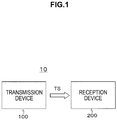
- FIG. 1 shows a configuration example of a transmission and reception system 10 as an embodiment.
- This transmission and reception system 10 is configured to have a transmission device 100 and a reception device 200.
- the transmission device 100 transmits a transport stream TS as a container by causing the stream to be carried on broadcast waves.
- the transport stream TS includes a video stream having encoded image data of each of pictures which is obtained by encoding image data of the pictures which constitute image data of the interlacing scheme in the NAL unit structure.
- image data of the interlacing scheme is encoded in the High Efficiency Video Coding (HEVC) scheme.
- HEVC High Efficiency Video Coding
- this video stream is set to have encoded data of image data of pictures of each layer which is obtained by classifying image data of each picture constituting image data of the interlacing scheme into a plurality of layers.
- encoding is performed such that a reference source picture is affiliated to its own layer and/or a layer lower than its own layer.
- Layer identification information for identifying an affiliated layer of each picture is added to encoded image data of pictures of each layer.
- Layer identification information (“nuh_temporal_id_plus1" which means temporal_id) is disposed in the header part of an NAL unit (nal unit) of each picture.
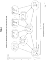
- FIG. 2 shows an example of hierarchical encoding performed by an encoder.
- layers are classified into four layers from 0 to 3, and encoding is performed on image data of pictures of each of the layers.
- the vertical axis represents layers. 0 to 3 are respectively set as temporal_id (layer identification information) which is disposed in the header part of an NAL unit (nal_unit) which constitutes encoded image data of pictures in Layers 0 to 3.
- the horizontal axis represents a display order (picture order of composition (POC)) with the left side thereof representing earlier positions and the right side thereof representing later positions in that order.
- POC picture order of composition
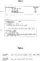
- FIG. 3(a) shows a structure example (syntax) of the header of an NAL unit
- FIG. 3(b) shows the content (semantics) of principal parameters in the structure example.
- the one-bit field of "forbidden_zero_bit” should have 0.
- the six-bit field of "nal_unit_type” represents the type of NAL unit.
- the six-bit field of "nuh_layer_id” is assumed to have 0.
- the three-bit field of "nuh_temporal_id_plusl” represents temporal_id, and has the value obtained by adding one (1 to 7).
- each of the rectangular frames represents a picture, and the number therein represents the position of a picture being encoded, i.e., in an encoding order (decoding order on a reception side).
- the solid-line arrows represent encoding reference relations between pictures.
- a structure of pictures (SOP) is constituted with 16 pictures from “0” to "17” (excluding “2” and “3"), and "0" is the leading picture.
- “2" is the leading picture of the next SOP.
- the structure of pictures (SOP) is constituted by 16 pictures from “2" to "3" and up to "17,” and in this case, "2" is the leading picture of the SOP.
- Two pictures surrounded by a dotted-line oval represent a field pair, "F” represents a first field (top field), and "S” represents a second field (bottom field). It should be noted that layers of two pictures forming a field pair are the same.
- the picture of "1" can be the leading picture of a group of pictures (GOP).
- Encoded image data of the leading picture of a GOP is composed of NAL units that are AUD, VPS, SPS, PPS, PSEI, SLICE, SSEI, and EOS as shown in FIG. 4 .
- a picture other than the leading picture of the GOP is composed of NAL units that are AUD, PPS, PSEI, SLICE, SSEI, and EOS.
- the VPS can be transmitted along with the SPS once in a sequence (GOP), and the PPS can be transmitted for each picture.
- an NAL unit type of a slice of encoded image data of a picture forming a field pair with a picture of an IRAP is set to a unique type which indicates a picture that is dependent on the picture of the IRAP and forms the field pair with the picture of the IRAP.
- an intra random access point (IRAP), a trailing picture (TP), and a leading picture (LP) are defined as the NAL unit types of a slice.
- An "IRAP” indicates an intra picture constituting a random access point, and includes each type of "BLA_W_LP,” “BLA W RADL,” “BLA_N_LP,” “IDR W RADL,” “IDR_N_LP,” and "CRA_NUT.”
- a "TP” indicates a picture later in a decoding order than the IRAP and later in a display order than the IRAP, and includes each type of "TRAIL_N” and “TRAIL_R.”
- An "LP” indicates a picture later in a decoding order than the IRAP and earlier in a display order than the IRAP, and includes each type of "RADL N,” “RADL_R,” “RASL_N,” and “RASL_R.”
- a picture forming a field pair with a picture of an IRAP becomes a TP later in a decoding order than the IRAP and later in a display order than the IRAP.
- the TP can serve as a succeeding picture as shown in FIG. 5 , leaving no room for insertion of an LP, and thus encoding of an open GOP is not possible.
- RAP_dependent a type called "RAP_dependent" is newly defined.
- This type indicates a picture which is not a picture of an IRAP but is dependent on a picture of an IRAP, and forms a field pair with the picture of the IRAP.
- an NAL unit type of a slice of encoded image data of a picture forming a field pair with a picture of an IRAP is set to RAP_dependent.
- an LP can be inserted as a succeeding picture, and thus encoding of an open GOP is possible.
- FIG. 7(a) schematically shows a closed GOP.
- a closed GOP is a GOP in which the leading I-picture in a decoding order is an instantaneous decoding refresh (IDR) picture.
- FIG. 7(b) schematically shows an open GOP.
- An open GOP is a GOP in which the leading I-picture in a decoding order is a non-IDR picture.
- an N-th GOP is assumed to be a GOP Nth and an (N-1)-th GOP is assumed to be a GOP (N-1)th.
- a GOP Nth an IDR picture comes first in a decoding order, an LP comes next, and a TP comes next after that.
- an LP comes first in a display order, an IDR picture of a non-IDR picture comes next, and a TP comes next after that.
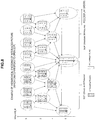
- FIG. 8 shows an example of hierarchical encoding when an NAL unit type of a slice of encoded image data of a picture forming a field pair with a picture of an IRAP is set to RAP_dependent.
- the vertical axis represents layers.
- the horizontal axis represents a display order (picture order of composition or POC) with the left side thereof representing earlier display times and the right side thereof representing later display times.
- layers are classified into four layers of 0 to 3 and encoding is performed on image data of pictures of each of the layers as in the example of FIG. 2 described above.
- each of the rectangular frames represents a picture
- the number therein represents the position of a picture being encoded, i.e., in the encoding order (decoding order on the reception side).
- the solid-line arrows represent encoding reference relations between pictures. Two pictures surrounded by a dotted-line oval represent a field pair, "F” represents a first field (top field), and "S” represents a second field (bottom field).
- a picture of "0" in Layer 0 is encoded as a picture of an IRAP.
- a picture of "1" forming a field pair with the picture of "0” is encoded as a picture of RAP_dependent.
- pictures of "2" to "15” in Layers 1 to 3 are encoded as LPs, and then pictures of "16" and “17” in Layer 0 and pictures of "18" to "31” in Layers 1 to 3 are encoded as TPs.
- enabling an LP to be inserted as a succeeding picture by setting an NAL unit type of a slice of encoded image data of a picture forming a field pair with a picture of an IRAP to RAP_dependent is not limited in hierarchical encoding.
- FIG. 9 shows an example of encoding in a stream order and a display order.
- an N-th GOP is assumed to be a GOP Nth
- an (N-1)-th GOP is assumed to be a GOP (N-1)th.
- each of the solid-line rectangular frames represent a picture, and the number therein represents the position of a picture being encoded, i.e., in an encoding order (a decoding order on a reception side).
- Two pictures surrounded by a dashed-line rectangular frame represent a field pair with a first field (top field) and a second field (bottom field).
- each picture of the GOP Nth is encoded as below, and thereby a video stream is generated.
- the picture of "0” is encoded as a picture of the IRAP.
- the picture of "1" forming a field pair with the picture of "0” is encoded as a picture of RAP_dependent.
- the pictures of "2" to "5" positioned before the picture of "0” in the display order are encoded as LPs, and then the pictures of "6" to "9” positioned after the picture of "1” in the display order are encoded as TPs.
- FIG. 10 also shows an example of encoding in a stream order and a display order. This example shows a case in which an NAL unit type of a slice of encoded image data of a picture forming a field pair with a picture of an IRAP is set to a TP, rather than RAP_dependent.
- the respective pictures of the GOP Nth are encoded as below, and thereby a video stream is generated.
- the picture of "0” is encoded as a picture of an IRAP.
- the picture of "1" forming the field pair with the picture of "0” is encoded as a TP.
- the pictures of "2" to “9” positioned after the picture of "1" in the display order are encoded as TPs.
- the reception device 200 receives the transport stream TS carried on and sent by broadcast waves from the transmission device 100.
- the reception device 200 selectively takes and decodes encoded image data of a layer equal to or lower than a predetermined layer from a video stream included in this transport stream TS according to its own decoding capability, acquires image data of each of pictures, and thereby obtains image data in the interlacing scheme.
- the reception device 200 converts the image data in the interlacing scheme obtained through the decoding described above into image data in a progressive scheme, and further performs post-processing to cause the frame rate thereof to match a display capability. Through this post-processing, it is possible to obtain image data of a frame rate commensurate with a high display capability even when, for example, a decoding capability is low.
- FIG. 11 shows a configuration example of the transmission device 100.
- This transmission device 100 has an encoder 102, a compressed data buffer (coded picture buffer or cpb) 103, a multiplexer 104, and a transmission unit 105.
- a compressed data buffer coded picture buffer or cpb
- the encoder 102 receives an input of uncompressed image data in the interlacing scheme and performs hierarchical encoding in the HEVC scheme.
- the encoder 102 classifies image data of each of pictures constituting the image data in the interlacing scheme into a plurality of layers, and generates a video stream having encoded data of the image data of pictures of each layer.
- the encoder 102 encodes data such that a picture to be referred to (reference source picture) is affiliated to its own layer and/or a layer lower than its own layer (see FIG. 2 ).
- the encoder 102 encodes each picture such that encoding of the open GOP becomes possible.
- the encoder 102 sets an NAL unit type of a slice of encoded image data of a picture forming a field pair with a picture of an IRAP to a unique type which indicates a picture that is dependent on the picture of the IRAP and forms the field pair with the picture of the IRAP.
- this unique type is the newly defined "RAP_dependent" as described above (see FIGS. 8 and 9 ).
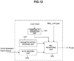
- FIG. 12 shows a configuration example of the encoder 102.
- This encoder 102 has a parameter set/SEI encoding unit 121, a slice encoding unit 122, an NAL packetizing unit 123, and a temporal ID generation unit 124.
- the parameter set/SEI encoding unit 121 generates parameter sets such as a VPS, an SPS, a PPS, and the like and SEI of pictures of each layer according to the number of streams to be encoded.
- the slice encoding unit 122 obtains slice data by encoding image data of pictures of each layer.
- the NAL packetizing unit 123 generates encoded image data of the pictures of each layer based on the parameter sets and SEI generated by the parameter set/SEI encoding unit 121 and the slice data generated by the slice encoding unit 122, and obtains video streams (encoded streams).
- the temporal ID generation unit 124 generates temporal_id for each picture to be encoded based on layer information of the picture, and sends the data to the NAL packetizing unit 123.
- the NAL packetizing unit 123 receives information of the NAL unit type of each picture to be encoded.
- the NAL packetizing unit 123 inserts temporal_id corresponding to a picture of each layer into the header of the NAL unit constituting encoded image data of the picture and further sets an NAL unit type (see FIG. 3 ).
- the compressed data buffer (cpb) 103 temporarily accumulates a video stream including the encoded data of the pictures of each layer obtained by the encoder 102.
- the multiplexer 104 reads the video stream accumulated in the compressed data buffer 103, makes them into PES packets, further makes them into transport packets and multiplexes them, and thereby obtains a transport stream TS as a multiplexed stream.
- This transport stream TS includes a single video stream having the encoded image data of the pictures of each layer, or a predetermined number of video streams having the encoded image data of the pictures of each layer set that is obtained by dividing the plurality layers into a predetermined number of layer sets, the number being equal to or greater than two.
- the multiplexer 104 inserts layer information and stream configuration information into the transport stream TS.
- the transport stream TS includes a program map table (PMT).
- PMT program map table
- This PMT has a video elementary loop (video ES1 loop) with information relating to each video stream.
- video ES1 loop information of a stream type, a packet identifier (PID), and the like as well as a descriptor describing the information relating to the video stream are disposed to correspond to each video stream.
- PID packet identifier
- the transmission unit 105 modulates the transport stream TS in a modulation scheme proper for broadcasting, for example, QPSK-OFDM, and transmits an RF modulation signal from a transmission antenna.
- a modulation scheme proper for broadcasting for example, QPSK-OFDM
- the encoder 102 receives an input of uncompressed image data in an interlacing scheme.
- the encoder 102 performs hierarchical encoding on this image data in an HEVC scheme.
- the encoder 102 classifies image data of respective pictures constituting the image data into a plurality of layers and encodes the data, and thereby generates a video stream having encoded image data of the pictures of each layer.
- encoding is performed such that a picture to be referred to is affiliated to its own layer and/or a layer lower than its own layer.
- each picture is encoded such that encoding of an open GOP becomes possible.
- an NAL unit type of a slice of encoded image data of a picture forming a field pair with a picture of an IRAP is set to "RAP_dependent" which is a unique type which indicates a picture that is dependent on the picture of the IRAP and forms the field pair with the picture of the IRAP.
- the video stream which is generated by the encoder 102, including the encoded data of the pictures of each layer, is supplied to the compressed data buffer (cpb) 103 and temporarily stored therein.
- the video stream accumulated in the compressed data buffer 103 is read, PES packetized, and further transport packetized and multiplexed, and thereby a transport stream TS is obtained as a multiplexed stream.
- the transport stream TS obtained by the multiplexer 104 is sent to the transmission unit 105.
- the transport stream TS is modulated in a modulation scheme proper for broadcasting, for example, QPSK-OFDM, and an RF modulation signal is transmitted from a transmission antenna.
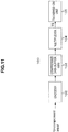
- FIG. 13 shows a configuration example of the reception device 200.
- This reception device 200 has a reception unit 202, a demultiplexer 203, and a compressed data buffer (coded picture buffer or cpb) 204. Further, the reception device 200 has a decoder 205, an uncompressed data buffer (decoded picture buffer or dpb) 206, and a post-processing unit 207.
- the reception unit 202 demodulates an RF modulation signal received by a reception antenna to acquire the transport stream TS.
- the demultiplexer 203 takes out a video stream (encoded stream) by performing a depacketizing process on the transport stream TS and sends the stream to the compressed data buffer (coded picture buffer or cpb) 204.
- the compressed data buffer (cpb) 204 temporarily accumulates the video stream taken out by the demultiplexer 203.
- the decoder 205 takes out encoded image data of pictures of a layer that has been designated as a layer to be decoded from the video stream accumulated in the compressed data buffer 204. Then, the decoder 205 decodes the taken encoded image data of each picture at each decoding timing of the picture, and sends the data to the uncompressed data buffer (dpb) 206.
- the decoder 205 reads and uses image data of a reference source picture from the uncompressed data buffer 206 when necessary.
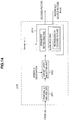
- FIG. 14 shows a configuration example of the decoder 205.
- This decoder 205 has a temporal ID analysis unit 251, a target layer selection unit 252, and a decoding unit 253.
- the temporal ID analysis unit 251 reads the video stream (encoded stream) accumulated in the compressed data buffer 204 and analyzes temporal_id inserted into the NAL unit header of the encoded image data of each picture.
- the target layer selection unit 252 takes out encoded image data of each picture of a layer designated as a layer to be decoded from the video stream read from the compressed data buffer 204 based on the analysis result of the temporal ID analysis unit 251, and sends the data to the decoding unit 253.
- the decoding unit 253 sequentially decodes the encoded image data of each picture acquired by the target layer selection unit 252 at decoding timings, and sends the data to the uncompressed data buffer (dpb) 206.
- the decoding unit 253 analyzes the VPS and the SPS to ascertain a level designation value of a bit rate of each sublayer "sublayer_level_idc,” and checks whether decoding is possible within the decoding capability. In addition, in this case, the decoding unit 253 analyzes the SEI to ascertain, for example, "initial_cpb_removal_time” and "cpb_removal_delay,” and checks whether a decoding timing is proper. Alternatively, decoding is started at a decoding timing obtained from a DTS (decoding timestamp) obtained by the demultiplexer 203. In addition, display is performed at a display timing obtained from a PTS (presentation timestamp) obtained by the demultiplexer 203.
- DTS decoding timestamp
- PTS presentation timestamp
- the decoding unit 253 acquires information which indicates a prediction destination in a time direction from a slice header when a slice is decoded to perform time-direction prediction. In addition, when a slice is decoded, the decoding unit 253 manages a reading order after decoding for each type of the IRAP, RAP_dependent, an LP and a TP described in the NAL unit type of the NAL unit header.
- the uncompressed data buffer (dpb) 206 temporarily accumulates the image data of each picture decoded by the decoder 205.
- the post-processing unit 207 converts the image data in the interlacing scheme sequentially read from the uncompressed data buffer (dpb) 206 at display timings into image data in the progressive scheme. Furthermore, the post-processing unit 207 performs a process of causing the frame rate of the image data of each picture converted into the progressive scheme to match the display capability.
- the post-processing unit 207 sends the decoded image data of the pictures to a display as it is.
- the post-processing unit 207 performs a subsampling process so that time-direction resolution is half that of the decoded image data of the pictures, and sends the data to the display as image data of 60 fps.
- the post-processing unit 207 performs I-P conversion on the decoded image data of each picture to set the progressive frame rate to 60 fps, further performs an interpolation process to set time direction resolution to twice that of pictures of the 60 fps, and sends the data to a display as image data of 120 fps.
- the post-processing unit 207 sends the decoded image data of each picture directly to the display.
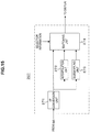
- FIG. 15 shows a configuration example of the post-processing unit 270. This is an example which can deal with the case described above in which the frame rate of the decoded image data of the pictures is 120 fps or 60 fps and the display capability is 120 fps or 60 fps,
- the post-processing unit 207 has an I-P conversion unit 271, an interpolation unit 272, a subsampling unit 273, and a switching unit 274.
- the I-P conversion unit 271 converts image data of each picture after decoding (image data in the interlacing scheme) from the uncompressed data buffer 206 into image data in the progressive scheme.
- the interpolation unit 272 performs an interpolation process in the time direction on the image data obtained by the I-P conversion unit 271 to double the frame rate.
- the subsampling unit 273 performs a subsampling process in the time direction on the image data obtained by the I-P conversion unit 271 to halve the frame rate.
- the switching unit 274 selectively outputs any output image data of the I-P conversion unit 271, the interpolation unit 272, and the subsampling unit 273 based on selection information.
- the selection information is automatically generated by, for example, a control unit that is not illustrated or according to a user operation. Accordingly, image data of each picture sequentially read from the uncompressed data buffer (dpb) 206 at display timings is converted into the progressive scheme, and the frame rate matches the display capability.
- the reception unit 202 demodulates the RF modulation signal received by the reception antenna to acquire the transport stream TS.
- This transport stream TS is sent to the demultiplexer 203.
- the demultiplexer 203 takes a video stream (encoded stream) by performing a depacketizing process on the transport stream TS.
- This video stream is sent to and temporarily accumulated in the compressed data buffer (cpb) 204.
- the decoder 205 takes the encoded image data of the pictures of the layer designated as a layer to be decoded from the video stream accumulated in the compressed data buffer 204. Then, the decoder 205 decodes the encoded image data of each of the taken pictures at decoding timings of the pictures, and sends the data to the uncompressed data buffer (dpb) 206 to cause the data to be temporarily stored. In this case, when the encoded image data of the respective pictures is to be decoded, image data of a reference source picture is read from the uncompressed data buffer 206 to be used.
- the image data of the pictures sequentially read from the uncompressed data buffer (dpb) 206 at display timings is sent to the post-processing unit 207.
- the post-processing unit 207 converts the image data in the interlacing scheme into image data in the progressive scheme, and further performs an interpolation process or a subsampling process on the image data of each picture converted into the progressive scheme to cause the frame rate thereof to match the display capability.
- the image data of the pictures processed by the post-processing unit 207 is supplied to the display and a dynamic image of the image data of the pictures is displayed.
- the transmission side sets an NAL unit type of a slice of encoded image data of a picture forming a field pair with an intra picture constituting a random access point to a unique type which indicates a picture that is dependent on the intra picture and forms the field pair with the intra picture (to "RAP_dependent").
- RAP_dependent a unique type which indicates a picture that is dependent on the intra picture and forms the field pair with the intra picture
- the transmission and reception system 10 constituted by the transmission device 100 and the reception device 200
- a configuration of a transmission and reception system to which the present technology can be applied is not limited thereto.
- the reception device 200 part may be configured with a set-top box connected with a digital interface such as High-Definition Multimedia Interface (HDMI) and a monitor, or the like.
- HDMI High-Definition Multimedia Interface
- the above-described embodiment shows the example in which the container is a transport stream (MPEG-2 TS).
- MPEG-2 TS transport stream
- the present technology can also be similarly applied to a system configured to distribute data to a reception terminal using a network such as the Internet.
- a network such as the Internet.
- MP4 transport stream
- the main feature of the present technology is to enable insertion of an LP as a succeeding picture possible and encoding of an open GOP possible by setting, when image data in the interlacing scheme is encoded in the form of an NAL unit, an NAL unit type of a slice of encoded image data of a picture forming a field pair with an intra picture constituting a random access point to a unique type which indicates a picture that is dependent on the intra picture and forms the field pair with the intra picture (see FIGS. 8 and 9 ).
Description
- The present technology relates to an encoding device, an encoding method, a transmission device, a decoding device, a decoding method, and a reception device. More particularly, the present technology relates to an encoding device which encodes image data in an interlacing scheme in an NAL unit structure.
- Encoding schemes of encoding image data in an NAL unit structure are known in the related art. For example,
Non-Patent Literature 1 discloses encoding in a High Efficiency Video Coding (HEVC) scheme. - Non-Patent Literature 1: "Overview of the High Efficiency Video Coding (HEVC) Standard" written by Gary J. Sullivan, Jens-Rainer Ohm, Woo-Jin Han, and Thomas Wiegand, IEEE TRANSACTIONS ON CIRCUITS AND SYSTEMS FOR VIDEO TECNOROGY, VOL. 22, NO. 12, pp. 1649-1668, December 2012.
- Document BARROUX G ET AL: "Proposal of interlace coding tools for HEVC", 105. MPEG MEETING; 29-7-2013 - 2-8-2013; VIENNA; (MOTION PICTURE EXPERT GROUP OR ISO/IEC JTC1/SC29/WG11), no. m30452, 27 July 2013, discloses a summary of interlace coding tools proposed in HEVC, disclosing sequence-adaptive frame-field coding (SAFF), and picture-adaptive frame-field coding (PAFF). In PAFF, each field-pair is encoded as two distinct field pictures, the second field in display order is decoded immediately after the first field in display order.
- Document CHOI B ET AL: "MV-HEVC/SHVC HLS: Random access of multiple layers", 14. JCT-VC MEETING; 25-7-2013 - 2-8-2013; VIENNA; (JOINT COLLABORATIVE TEAM ON VIDEO CODING OF ISO/IEC JTC1/SC29/WG11 AND ITU-T SG.16); URL: HTTP://WFTP3.ITU.INT/ AV-ARCH/JCTVC-SITE/, no. JCTVC-N0121, 18 July 2013, discloses a definition of IRAP Access Units (AU), for random access in HEVC layered coding, for field coded pictures.
- When image data of the interlacing scheme is encoded in the HEVC scheme, if a picture forming a field pair with an intra picture constituting a random access point is set to a trailing picture (TP), there is no way to insert a leading picture (LP). Thus, in that case, it is not possible to encode an open Group of Pictures (open GOP).
- An objective of the present technology is to enable image data of the interlacing scheme to undergo encoding of an open GOP.
- In accordance with the invention, an encoding device is provided as set out in appended
claim 1, an encoding method as set out in appendedclaim 3, as well as a transmission device as set out in appendedclaim 4. - Here, the NAL unit type of a slice of encoded image data of a picture forming a field pair with an intra picture constituting a random access point is set to a unique type which indicates a picture that is dependent on the intra picture and forms the field pair with the intra picture. For this reason, an LP can be inserted as a succeeding picture and thus encoding of an open GOP becomes possible.
- Furthermore, in accordance with the invention, a decoding device is provided as set out in appended
claim 5, a decoding method as set out in appendedclaim 7, as well as a reception device as set out in appendedclaim 8. - In the video stream, the NAL unit type of a slice of encoded image data of a picture forming a field pair with an intra picture constituting a random access point is set to a unique type which indicates a picture that is dependent on the intra picture and forms the field pair with the intra picture. For this reason, the video stream may be subject to encoding of an open GOP which includes an LP.
- According to the present technology, encoding of an open GOP can also be performed for image data in an interlacing scheme. It should be noted that the effects described herein are not necessarily limitative, and any effect described in the present disclosure may be exhibited.
-
- [
FIG. 1] FIG. 1 is a block diagram showing a configuration example of a transmission and reception system of an embodiment. - [
FIG. 2] FIG. 2 is a diagram showing an example of hierarchical encoding of image data of the interlacing scheme performed by an encoder. - [
FIG. 3] FIG. 3 is a diagram showing a structure example (syntax) of an NAL unit header and the content (semantics) of principal parameters in the structure example. - [
FIG. 4] FIG. 4 is a diagram for describing a configuration of encoded image data of each picture based on HEVC. - [
FIG. 5] FIG. 5 is a diagram showing an example of hierarchical encoding of image data of the interlacing scheme performed by an encoder. - [
FIG. 6] FIG. 6 is a diagram showing an example of hierarchical encoding of image data of the interlacing scheme performed by an encoder. - [
FIG. 7] FIG. 7 is a diagram for describing a closed GOP and an open GOP. - [
FIG. 8] FIG. 8 is a diagram showing an example of hierarchical encoding when an NAL unit type of slice of encoded image data of a picture forming a field pair with a picture of an IRAP is set to RAP_dependent. - [
FIG. 9] FIG. 9 is a diagram showing an example of encoding of image data of the interlacing scheme by an encoder. - [
FIG. 10] FIG. 10 is a diagram showing another example of encoding of image data of the interlacing scheme by an encoder. - [
FIG. 11] FIG. 11 is a block diagram showing a configuration example of a transmission device. - [
FIG. 12] FIG. 12 is a block diagram showing a configuration example of an encoder. - [
FIG. 13] FIG. 13 is a block diagram showing a configuration example of a reception device. - [
FIG. 14] FIG. 14 is a block diagram showing a configuration example of a decoder. - [
FIG. 15] FIG. 15 is a block diagram showing a configuration example of a post-processing unit. - Hereinafter, embodiments for implementing this technology (hereinafter referred to as "embodiments") will be described. Note that description will be provided in the following order.
- 1. Embodiment
- 2. Modified example
-
FIG. 1 shows a configuration example of a transmission andreception system 10 as an embodiment. This transmission andreception system 10 is configured to have atransmission device 100 and areception device 200. - The
transmission device 100 transmits a transport stream TS as a container by causing the stream to be carried on broadcast waves. The transport stream TS includes a video stream having encoded image data of each of pictures which is obtained by encoding image data of the pictures which constitute image data of the interlacing scheme in the NAL unit structure. In this embodiment, image data of the interlacing scheme is encoded in the High Efficiency Video Coding (HEVC) scheme. - In addition, this video stream is set to have encoded data of image data of pictures of each layer which is obtained by classifying image data of each picture constituting image data of the interlacing scheme into a plurality of layers. In this case, encoding is performed such that a reference source picture is affiliated to its own layer and/or a layer lower than its own layer.
- Layer identification information for identifying an affiliated layer of each picture is added to encoded image data of pictures of each layer. Layer identification information ("nuh_temporal_id_plus1" which means temporal_id) is disposed in the header part of an NAL unit (nal unit) of each picture. By adding the layer identification information in this manner, a reception side can selectively take out encoded image data of a layer equal to or lower than a predetermined layer and perform a decoding process thereon.
-
FIG. 2 shows an example of hierarchical encoding performed by an encoder. In this example, layers are classified into four layers from 0 to 3, and encoding is performed on image data of pictures of each of the layers. The vertical axis represents layers. 0 to 3 are respectively set as temporal_id (layer identification information) which is disposed in the header part of an NAL unit (nal_unit) which constitutes encoded image data of pictures inLayers 0 to 3. The horizontal axis represents a display order (picture order of composition (POC)) with the left side thereof representing earlier positions and the right side thereof representing later positions in that order. -
FIG. 3(a) shows a structure example (syntax) of the header of an NAL unit, andFIG. 3(b) shows the content (semantics) of principal parameters in the structure example. The one-bit field of "forbidden_zero_bit" should have 0. The six-bit field of "nal_unit_type" represents the type of NAL unit. The six-bit field of "nuh_layer_id" is assumed to have 0. The three-bit field of "nuh_temporal_id_plusl" represents temporal_id, and has the value obtained by adding one (1 to 7). - Returning to
FIG. 2 , each of the rectangular frames represents a picture, and the number therein represents the position of a picture being encoded, i.e., in an encoding order (decoding order on a reception side). The solid-line arrows represent encoding reference relations between pictures. A structure of pictures (SOP) is constituted with 16 pictures from "0" to "17" (excluding "2" and "3"), and "0" is the leading picture. "2" is the leading picture of the next SOP. Alternatively, excluding "0" and "1," the structure of pictures (SOP) is constituted by 16 pictures from "2" to "3" and up to "17," and in this case, "2" is the leading picture of the SOP. Two pictures surrounded by a dotted-line oval represent a field pair, "F" represents a first field (top field), and "S" represents a second field (bottom field). It should be noted that layers of two pictures forming a field pair are the same. - The picture of "1" can be the leading picture of a group of pictures (GOP). Encoded image data of the leading picture of a GOP is composed of NAL units that are AUD, VPS, SPS, PPS, PSEI, SLICE, SSEI, and EOS as shown in
FIG. 4 . On the other hand, a picture other than the leading picture of the GOP is composed of NAL units that are AUD, PPS, PSEI, SLICE, SSEI, and EOS. The VPS can be transmitted along with the SPS once in a sequence (GOP), and the PPS can be transmitted for each picture. - In the present embodiment, encoding of an open GOP is possible. In other words, an NAL unit type of a slice of encoded image data of a picture forming a field pair with a picture of an IRAP is set to a unique type which indicates a picture that is dependent on the picture of the IRAP and forms the field pair with the picture of the IRAP.
- In encoding in the HEVC scheme, an intra random access point (IRAP), a trailing picture (TP), and a leading picture (LP) are defined as the NAL unit types of a slice. An "IRAP" indicates an intra picture constituting a random access point, and includes each type of "BLA_W_LP," "BLA W RADL," "BLA_N_LP," "IDR W RADL," "IDR_N_LP," and "CRA_NUT."
- A "TP" indicates a picture later in a decoding order than the IRAP and later in a display order than the IRAP, and includes each type of "TRAIL_N" and "TRAIL_R." An "LP" indicates a picture later in a decoding order than the IRAP and earlier in a display order than the IRAP, and includes each type of "RADL N," "RADL_R," "RASL_N," and "RASL_R."
- Originally, a picture forming a field pair with a picture of an IRAP becomes a TP later in a decoding order than the IRAP and later in a display order than the IRAP. In this case, only the TP can serve as a succeeding picture as shown in
FIG. 5 , leaving no room for insertion of an LP, and thus encoding of an open GOP is not possible. - In this embodiment, a type called "RAP_dependent" is newly defined. This type indicates a picture which is not a picture of an IRAP but is dependent on a picture of an IRAP, and forms a field pair with the picture of the IRAP. Accordingly, an NAL unit type of a slice of encoded image data of a picture forming a field pair with a picture of an IRAP is set to RAP_dependent. In this case, an LP can be inserted as a succeeding picture, and thus encoding of an open GOP is possible.
- The concepts of a closed GOP and an open GOP will be described.
FIG. 7(a) schematically shows a closed GOP. A closed GOP is a GOP in which the leading I-picture in a decoding order is an instantaneous decoding refresh (IDR) picture.FIG. 7(b) schematically shows an open GOP. An open GOP is a GOP in which the leading I-picture in a decoding order is a non-IDR picture. - As shown in the drawing, an N-th GOP is assumed to be a GOP Nth and an (N-1)-th GOP is assumed to be a GOP (N-1)th. In a GOP Nth, an IDR picture comes first in a decoding order, an LP comes next, and a TP comes next after that. In addition, in the GOP Nth, an LP comes first in a display order, an IDR picture of a non-IDR picture comes next, and a TP comes next after that.
- In the case of a closed GOP, when decoding starts from the beginning of a GOP Nth, decoding of all pictures included in the GOP Nth is guaranteed. In other words, the IDR picture is decoded first and then the LP is decoded. This LP is prohibited from overtaking the IDR picture in the decoding order to refer to a GOP (N-1)th. For this reason, when there is an LP, the LP is permitted only to refer to a picture include in the GOP Nth, and thus it can be decoded without information of the GOP (N-1)th. Likewise, since a TP is also prohibited to refer to the GOP (N-1)th, it can be decoded without information of the GOP (N-1)th.
- On the other hand, in the case of an open GOP, when decoding starts from the beginning of a GOP Nth, an LP which is earlier than a non-IDR picture in a display order is permitted to refer to a GOP (N-1)th, and thus it may be undecodable. It should be noted that, since a TP is prohibited from referring to the GOP (N-1)th, it can be decoded without information of the GOP (N-1)th.
- In this manner, when decoding starts from the beginning of a GOP Nth, all pictures included in the GOP Nth, can be decoded in the case of a closed GOP, but in the case of an open GOP, it is not possible to decode an LP. On the other hand, since referring to a GOP (N-1)th is not permitted in the case of a closed GOP, a bit rate thereof becomes higher than an open GOP to obtain the same image quality. For this reason, a closed GOP and an open GOP were separately used according to a situation in the past.
-
FIG. 8 shows an example of hierarchical encoding when an NAL unit type of a slice of encoded image data of a picture forming a field pair with a picture of an IRAP is set to RAP_dependent. The vertical axis represents layers. The horizontal axis represents a display order (picture order of composition or POC) with the left side thereof representing earlier display times and the right side thereof representing later display times. In this example, layers are classified into four layers of 0 to 3 and encoding is performed on image data of pictures of each of the layers as in the example ofFIG. 2 described above. - In this example, each of the rectangular frames represents a picture, and the number therein represents the position of a picture being encoded, i.e., in the encoding order (decoding order on the reception side). The solid-line arrows represent encoding reference relations between pictures. Two pictures surrounded by a dotted-line oval represent a field pair, "F" represents a first field (top field), and "S" represents a second field (bottom field).
- In this example, a picture of "0" in
Layer 0 is encoded as a picture of an IRAP. Next, a picture of "1" forming a field pair with the picture of "0" is encoded as a picture of RAP_dependent. Then, pictures of "2" to "15" inLayers 1 to 3 are encoded as LPs, and then pictures of "16" and "17" inLayer 0 and pictures of "18" to "31" inLayers 1 to 3 are encoded as TPs. - In this example, by encoding the picture of "1" forming a field pair with the picture of "0" which is the picture of the IRAP as a picture of RAP_dependent, insertion of an LP thereafter is possible. For this reason, encoding of an open GOP is possible.
- It should be noted that enabling an LP to be inserted as a succeeding picture by setting an NAL unit type of a slice of encoded image data of a picture forming a field pair with a picture of an IRAP to RAP_dependent is not limited in hierarchical encoding.
-
FIG. 9 shows an example of encoding in a stream order and a display order. In this example, an N-th GOP is assumed to be a GOP Nth, and an (N-1)-th GOP is assumed to be a GOP (N-1)th. In addition, each of the solid-line rectangular frames represent a picture, and the number therein represents the position of a picture being encoded, i.e., in an encoding order (a decoding order on a reception side). Two pictures surrounded by a dashed-line rectangular frame represent a field pair with a first field (top field) and a second field (bottom field). - In this example, each picture of the GOP Nth is encoded as below, and thereby a video stream is generated. In other words, the picture of "0" is encoded as a picture of the IRAP. Next, the picture of "1" forming a field pair with the picture of "0" is encoded as a picture of RAP_dependent. Then, the pictures of "2" to "5" positioned before the picture of "0" in the display order are encoded as LPs, and then the pictures of "6" to "9" positioned after the picture of "1" in the display order are encoded as TPs.
- In this example, by encoding the picture of "1" as a picture of RAP_dependent as described above, insertion of an LP thereafter is possible. Thus, encoding of an open GOP is possible.
-
FIG. 10 also shows an example of encoding in a stream order and a display order. This example shows a case in which an NAL unit type of a slice of encoded image data of a picture forming a field pair with a picture of an IRAP is set to a TP, rather than RAP_dependent. - In this example, the respective pictures of the GOP Nth are encoded as below, and thereby a video stream is generated. In other words, the picture of "0" is encoded as a picture of an IRAP. Next, the picture of "1" forming the field pair with the picture of "0" is encoded as a TP. Then, the pictures of "2" to "9" positioned after the picture of "1" in the display order are encoded as TPs.
- In this example, by encoding the picture of "1" as a TP as described above, succeeding pictures become only TPs. For this reason, encoding of an open GOP that is based on the premise of insertion of an LP is not possible.
- Returning to
FIG. 1 , thereception device 200 receives the transport stream TS carried on and sent by broadcast waves from thetransmission device 100. Thereception device 200 selectively takes and decodes encoded image data of a layer equal to or lower than a predetermined layer from a video stream included in this transport stream TS according to its own decoding capability, acquires image data of each of pictures, and thereby obtains image data in the interlacing scheme. - In addition, the
reception device 200 converts the image data in the interlacing scheme obtained through the decoding described above into image data in a progressive scheme, and further performs post-processing to cause the frame rate thereof to match a display capability. Through this post-processing, it is possible to obtain image data of a frame rate commensurate with a high display capability even when, for example, a decoding capability is low. -
FIG. 11 shows a configuration example of thetransmission device 100. Thistransmission device 100 has anencoder 102, a compressed data buffer (coded picture buffer or cpb) 103, amultiplexer 104, and atransmission unit 105. - The
encoder 102 receives an input of uncompressed image data in the interlacing scheme and performs hierarchical encoding in the HEVC scheme. Theencoder 102 classifies image data of each of pictures constituting the image data in the interlacing scheme into a plurality of layers, and generates a video stream having encoded data of the image data of pictures of each layer. In this case, theencoder 102 encodes data such that a picture to be referred to (reference source picture) is affiliated to its own layer and/or a layer lower than its own layer (seeFIG. 2 ). - At this time, the
encoder 102 encodes each picture such that encoding of the open GOP becomes possible. In other words, theencoder 102 sets an NAL unit type of a slice of encoded image data of a picture forming a field pair with a picture of an IRAP to a unique type which indicates a picture that is dependent on the picture of the IRAP and forms the field pair with the picture of the IRAP. In this embodiment, this unique type is the newly defined "RAP_dependent" as described above (seeFIGS. 8 and9 ). -
FIG. 12 shows a configuration example of theencoder 102. Thisencoder 102 has a parameter set/SEI encoding unit 121, aslice encoding unit 122, anNAL packetizing unit 123, and a temporal ID generation unit 124. - The parameter set/
SEI encoding unit 121 generates parameter sets such as a VPS, an SPS, a PPS, and the like and SEI of pictures of each layer according to the number of streams to be encoded. Theslice encoding unit 122 obtains slice data by encoding image data of pictures of each layer. - The
NAL packetizing unit 123 generates encoded image data of the pictures of each layer based on the parameter sets and SEI generated by the parameter set/SEI encoding unit 121 and the slice data generated by theslice encoding unit 122, and obtains video streams (encoded streams). - The temporal ID generation unit 124 generates temporal_id for each picture to be encoded based on layer information of the picture, and sends the data to the
NAL packetizing unit 123. TheNAL packetizing unit 123 receives information of the NAL unit type of each picture to be encoded. TheNAL packetizing unit 123 inserts temporal_id corresponding to a picture of each layer into the header of the NAL unit constituting encoded image data of the picture and further sets an NAL unit type (seeFIG. 3 ). - Returning to
FIG. 11 , the compressed data buffer (cpb) 103 temporarily accumulates a video stream including the encoded data of the pictures of each layer obtained by theencoder 102. Themultiplexer 104 reads the video stream accumulated in thecompressed data buffer 103, makes them into PES packets, further makes them into transport packets and multiplexes them, and thereby obtains a transport stream TS as a multiplexed stream. - This transport stream TS includes a single video stream having the encoded image data of the pictures of each layer, or a predetermined number of video streams having the encoded image data of the pictures of each layer set that is obtained by dividing the plurality layers into a predetermined number of layer sets, the number being equal to or greater than two. The
multiplexer 104 inserts layer information and stream configuration information into the transport stream TS. - As one of program specific information (PSI), the transport stream TS includes a program map table (PMT). This PMT has a video elementary loop (video ES1 loop) with information relating to each video stream. In this video elementary loop, information of a stream type, a packet identifier (PID), and the like as well as a descriptor describing the information relating to the video stream are disposed to correspond to each video stream.
- The
transmission unit 105 modulates the transport stream TS in a modulation scheme proper for broadcasting, for example, QPSK-OFDM, and transmits an RF modulation signal from a transmission antenna. - An operation of the
transmission device 100 shown inFIG. 11 will be briefly described. Theencoder 102 receives an input of uncompressed image data in an interlacing scheme. Theencoder 102 performs hierarchical encoding on this image data in an HEVC scheme. In other words, theencoder 102 classifies image data of respective pictures constituting the image data into a plurality of layers and encodes the data, and thereby generates a video stream having encoded image data of the pictures of each layer. At this time, encoding is performed such that a picture to be referred to is affiliated to its own layer and/or a layer lower than its own layer. - In addition, at this time, each picture is encoded such that encoding of an open GOP becomes possible. In other words, an NAL unit type of a slice of encoded image data of a picture forming a field pair with a picture of an IRAP is set to "RAP_dependent" which is a unique type which indicates a picture that is dependent on the picture of the IRAP and forms the field pair with the picture of the IRAP.
- The video stream which is generated by the
encoder 102, including the encoded data of the pictures of each layer, is supplied to the compressed data buffer (cpb) 103 and temporarily stored therein. In themultiplexer 104, the video stream accumulated in thecompressed data buffer 103 is read, PES packetized, and further transport packetized and multiplexed, and thereby a transport stream TS is obtained as a multiplexed stream. - The transport stream TS obtained by the
multiplexer 104 is sent to thetransmission unit 105. In thetransmission unit 105, the transport stream TS is modulated in a modulation scheme proper for broadcasting, for example, QPSK-OFDM, and an RF modulation signal is transmitted from a transmission antenna. -
FIG. 13 shows a configuration example of thereception device 200. Thisreception device 200 has areception unit 202, ademultiplexer 203, and a compressed data buffer (coded picture buffer or cpb) 204. Further, thereception device 200 has adecoder 205, an uncompressed data buffer (decoded picture buffer or dpb) 206, and apost-processing unit 207. - The
reception unit 202 demodulates an RF modulation signal received by a reception antenna to acquire the transport stream TS. Thedemultiplexer 203 takes out a video stream (encoded stream) by performing a depacketizing process on the transport stream TS and sends the stream to the compressed data buffer (coded picture buffer or cpb) 204. - The compressed data buffer (cpb) 204 temporarily accumulates the video stream taken out by the
demultiplexer 203. Thedecoder 205 takes out encoded image data of pictures of a layer that has been designated as a layer to be decoded from the video stream accumulated in thecompressed data buffer 204. Then, thedecoder 205 decodes the taken encoded image data of each picture at each decoding timing of the picture, and sends the data to the uncompressed data buffer (dpb) 206. When decoding the encoded image data of each picture, thedecoder 205 reads and uses image data of a reference source picture from theuncompressed data buffer 206 when necessary. -
FIG. 14 shows a configuration example of thedecoder 205. Thisdecoder 205 has a temporalID analysis unit 251, a targetlayer selection unit 252, and adecoding unit 253. The temporalID analysis unit 251 reads the video stream (encoded stream) accumulated in thecompressed data buffer 204 and analyzes temporal_id inserted into the NAL unit header of the encoded image data of each picture. - The target
layer selection unit 252 takes out encoded image data of each picture of a layer designated as a layer to be decoded from the video stream read from the compresseddata buffer 204 based on the analysis result of the temporalID analysis unit 251, and sends the data to thedecoding unit 253. Thedecoding unit 253 sequentially decodes the encoded image data of each picture acquired by the targetlayer selection unit 252 at decoding timings, and sends the data to the uncompressed data buffer (dpb) 206. - In this case, the
decoding unit 253 analyzes the VPS and the SPS to ascertain a level designation value of a bit rate of each sublayer "sublayer_level_idc," and checks whether decoding is possible within the decoding capability. In addition, in this case, thedecoding unit 253 analyzes the SEI to ascertain, for example, "initial_cpb_removal_time" and "cpb_removal_delay," and checks whether a decoding timing is proper. Alternatively, decoding is started at a decoding timing obtained from a DTS (decoding timestamp) obtained by thedemultiplexer 203. In addition, display is performed at a display timing obtained from a PTS (presentation timestamp) obtained by thedemultiplexer 203. - The
decoding unit 253 acquires information which indicates a prediction destination in a time direction from a slice header when a slice is decoded to perform time-direction prediction. In addition, when a slice is decoded, thedecoding unit 253 manages a reading order after decoding for each type of the IRAP, RAP_dependent, an LP and a TP described in the NAL unit type of the NAL unit header. - Returning to
FIG. 13 , the uncompressed data buffer (dpb) 206 temporarily accumulates the image data of each picture decoded by thedecoder 205. Thepost-processing unit 207 converts the image data in the interlacing scheme sequentially read from the uncompressed data buffer (dpb) 206 at display timings into image data in the progressive scheme. Furthermore, thepost-processing unit 207 performs a process of causing the frame rate of the image data of each picture converted into the progressive scheme to match the display capability. - For example, when the frame rate of the decoded image data of the pictures is 120 fps and the display capability is 120 fps, the
post-processing unit 207 sends the decoded image data of the pictures to a display as it is. In addition, when, for example, the frame rate of the decoded image data of the pictures is 120 fps and the display capability is 60 fps, thepost-processing unit 207 performs a subsampling process so that time-direction resolution is half that of the decoded image data of the pictures, and sends the data to the display as image data of 60 fps. - In addition, when the decoded image data of each picture has an interlaced field rate of 60 fps and the display capability thereof is a progressive frame rate of 120 fps, the
post-processing unit 207 performs I-P conversion on the decoded image data of each picture to set the progressive frame rate to 60 fps, further performs an interpolation process to set time direction resolution to twice that of pictures of the 60 fps, and sends the data to a display as image data of 120 fps. In addition, for example, when the image data of each picture after decoding has a frame rate of 60 fps and the display capability thereof is 60 fps, thepost-processing unit 207 sends the decoded image data of each picture directly to the display. -
FIG. 15 shows a configuration example of the post-processing unit 270. This is an example which can deal with the case described above in which the frame rate of the decoded image data of the pictures is 120 fps or 60 fps and the display capability is 120 fps or 60 fps, - The
post-processing unit 207 has anI-P conversion unit 271, aninterpolation unit 272, asubsampling unit 273, and aswitching unit 274. TheI-P conversion unit 271 converts image data of each picture after decoding (image data in the interlacing scheme) from theuncompressed data buffer 206 into image data in the progressive scheme. - The
interpolation unit 272 performs an interpolation process in the time direction on the image data obtained by theI-P conversion unit 271 to double the frame rate. Thesubsampling unit 273 performs a subsampling process in the time direction on the image data obtained by theI-P conversion unit 271 to halve the frame rate. Theswitching unit 274 selectively outputs any output image data of theI-P conversion unit 271, theinterpolation unit 272, and thesubsampling unit 273 based on selection information. - The selection information is automatically generated by, for example, a control unit that is not illustrated or according to a user operation. Accordingly, image data of each picture sequentially read from the uncompressed data buffer (dpb) 206 at display timings is converted into the progressive scheme, and the frame rate matches the display capability.
- An operation of the
reception device 200 shown inFIG. 15 will be briefly described. Thereception unit 202 demodulates the RF modulation signal received by the reception antenna to acquire the transport stream TS. This transport stream TS is sent to thedemultiplexer 203. Thedemultiplexer 203 takes a video stream (encoded stream) by performing a depacketizing process on the transport stream TS. This video stream is sent to and temporarily accumulated in the compressed data buffer (cpb) 204. - The
decoder 205 takes the encoded image data of the pictures of the layer designated as a layer to be decoded from the video stream accumulated in thecompressed data buffer 204. Then, thedecoder 205 decodes the encoded image data of each of the taken pictures at decoding timings of the pictures, and sends the data to the uncompressed data buffer (dpb) 206 to cause the data to be temporarily stored. In this case, when the encoded image data of the respective pictures is to be decoded, image data of a reference source picture is read from theuncompressed data buffer 206 to be used. - The image data of the pictures sequentially read from the uncompressed data buffer (dpb) 206 at display timings is sent to the
post-processing unit 207. Thepost-processing unit 207 converts the image data in the interlacing scheme into image data in the progressive scheme, and further performs an interpolation process or a subsampling process on the image data of each picture converted into the progressive scheme to cause the frame rate thereof to match the display capability. The image data of the pictures processed by thepost-processing unit 207 is supplied to the display and a dynamic image of the image data of the pictures is displayed. - As described above, in the transmission and
reception system 10 shown inFIG. 1 , when image data in the interlacing scheme is encoded in the HEVC scheme, the transmission side sets an NAL unit type of a slice of encoded image data of a picture forming a field pair with an intra picture constituting a random access point to a unique type which indicates a picture that is dependent on the intra picture and forms the field pair with the intra picture (to "RAP_dependent"). Thus, inserting an LP as a succeeding picture becomes possible and thereby encoding of an open GOP becomes possible. - It should be noted that, although the above-described embodiment shows the transmission and
reception system 10 constituted by thetransmission device 100 and thereception device 200, a configuration of a transmission and reception system to which the present technology can be applied is not limited thereto. For example, thereception device 200 part may be configured with a set-top box connected with a digital interface such as High-Definition Multimedia Interface (HDMI) and a monitor, or the like. Note that "HDMI" is a registered trademark. - In addition, although a case of an interlaced-type image has been described in the above embodiment, also in the case of a progressive-type image, a picture is allowed to be disposed later than an IRAP in its decoding order and display order due to the type of RAP_dependent, and thus a stream in which LPs and RPs are flexibly arranged can be configured.
- In addition, the above-described embodiment shows the example in which the container is a transport stream (MPEG-2 TS). The present technology, however, can also be similarly applied to a system configured to distribute data to a reception terminal using a network such as the Internet. In distribution on the Internet, there are many cases of distribution using a container in MP4 or other formats. In other words, as containers, various formats including transport streams (MPEG-2 TS) employed in digital broadcasting standards, MP4 used in Internet distribution, and the like are equivalent thereto.
- The main feature of the present technology is to enable insertion of an LP as a succeeding picture possible and encoding of an open GOP possible by setting, when image data in the interlacing scheme is encoded in the form of an NAL unit, an NAL unit type of a slice of encoded image data of a picture forming a field pair with an intra picture constituting a random access point to a unique type which indicates a picture that is dependent on the intra picture and forms the field pair with the intra picture (see
FIGS. 8 and9 ). - The invention is set out in the appended claims.
-
- 10
- transmission and reception system
- 100
- transmission device
- 102
- encoder
- 103
- compressed data buffer (cpb)
- 104
- multiplexer
- 105
- transmission unit
- 121
- parameter set/SEI encoding unit
- 122
- slice encoding unit
- 123
- NAL packetizing unit
- 124
- temporal ID generation unit
- 200
- reception device
- 202
- reception unit
- 203
- demultiplexer
- 204
- compressed data buffer (cpb)
- 205
- decoder
- 206
- uncompressed data buffer (dpb)
- 207
- post-processing unit
- 251
- temporal ID analysis unit
- 252
- target layer selection unit
- 253
- decoding unit
- 271
- I-P conversion unit
- 272
- interpolation unit
- 273
- subsampling unit
- 274
- switching unit
Claims (8)
- An encoding device comprising:an image encoding unit (102) configured to encode image data of each picture constituting image data in an interlacing scheme in an NAL unit structure and generate a video stream having the encoded image data of each picture,wherein the image encoding unit is configured to set an NAL unit type of a slice of encoded image data of a picture, the picture forming a field pair with an intra picture constituting a random access point (IRAP), wherein the NAL unit type is set to a unique type which indicates that the picture is dependent on the intra picture and forms the field pair with the intra picture, andwherein the image encoding unit is configured to classify the image data of each picture constituting the image data in the interlacing scheme into a plurality of layers, encodes image data of a picture of each classified layer, and generates a video stream having the encoded image data of the picture of each layer.
- The encoding device according to claim 1, wherein the image encoding unit (102) encodes the image data in the interlacing scheme in an HEVC scheme.
- An encoding method comprising:an image encoding step by an image encoding unit of encoding image data of each picture constituting image data in an interlacing scheme in an NAL unit structure and generating a video stream having the encoded image data of each picture,wherein, in the image encoding step, an NAL unit type of a slice of encoded image data of a picture, the picture forming a field pair with an intra picture constituting a random access point (IRAP), wherein the NAL unit type is set to a unique type which indicates that the picture is dependent on the intra picture and forms the field pair with the intra picture, andwherein the image encoding unit classifies the image data of each picture constituting the image data in the interlacing scheme into a plurality of layers, encodes image data of a picture of each classified layer, and generates a video stream having the encoded image data of the picture of each layer.
- A transmission device comprising:the encoding device according to claim 1; anda transmission unit (105) configured to transmit a container in a predetermined format which includes a video stream generated by the encoding device.
- A decoding device comprising:an image decoding unit (205) configured to decode a video stream comprising a plurality of hierarchical layers of image data constituting image data in an interlacing scheme in an NAL unit structure, to obtain the image data in the interlacing scheme,wherein the image decoding unit (205) is configured to decode, from the video stream, an NAL unit type of a slice of encoded image data of a picture, wherein the NAL unit type is a unique type which indicates that the picture is dependent on an intra picture and forms a field pair with the intra picture, and the image decoding unit (205) is further configured to decode, based on the decoded NAL unit type, the picture forming the field pair with i the intra picture constituting a random access point (IRAP), andwherein the image decoding unit (205) is configured to decode, from the video stream, image data of each picture of each layer constituting the image data.
- The decoding device according to claim 5, further comprising:a scheme conversion unit configured to convert the image data in the interlacing scheme obtained by the image decoding unit into image data in a progressive scheme; anda post-processing unit configured to cause a frame rate of image data of each picture obtained by the scheme conversion unit to match a display capability.
- A decoding method comprising:an image decoding step by an image decoding unit of decoding a video stream comprising a plurality of hierarchical layers of image data constituting image data in an interlacing scheme in an NAL unit structure, to obtain the image data in the interlacing scheme,wherein decoding the video stream comprises decoding an NAL unit type of a slice of encoded image data of a picture, wherein the NAL unit type is a unique type which indicates that the picture is dependent on an intra picture and forms a field pair with the intra picture, and decoding the picture forming the field pair with the intra picture constituting a random access point , andwherein decoding the video stream comprises decoding image data of each picture of each layer constituting the image data
- A reception device comprising:a reception unit (200, 202) configured to receive a container in a predetermined format which includes a video stream comprising a plurality of hierarchical layers of image data constituting image data in an interlacing scheme in an NAL unit structure; andthe image decoding device according to claim 5, configured to decode the video stream included in the received container.
Applications Claiming Priority (2)
| Application Number | Priority Date | Filing Date | Title |
|---|---|---|---|
| JP2013172734 | 2013-08-22 | ||
| PCT/JP2014/071105 WO2015025747A1 (en) | 2013-08-22 | 2014-08-08 | Encoding device, encoding method, transmission device, decoding device, decoding method, and reception device |
Publications (3)
| Publication Number | Publication Date |
|---|---|
| EP3038365A1 EP3038365A1 (en) | 2016-06-29 |
| EP3038365A4 EP3038365A4 (en) | 2017-03-15 |
| EP3038365B1 true EP3038365B1 (en) | 2021-01-13 |
Family
ID=52483525
Family Applications (1)
| Application Number | Title | Priority Date | Filing Date |
|---|---|---|---|
| EP14837995.1A Active EP3038365B1 (en) | 2013-08-22 | 2014-08-08 | Encoding device, encoding method, transmission device, decoding device, decoding method, and reception device |
Country Status (7)
| Country | Link |
|---|---|
| US (1) | US10187646B2 (en) |
| EP (1) | EP3038365B1 (en) |
| JP (1) | JP6344392B2 (en) |
| CN (1) | CN105340277B (en) |
| BR (1) | BR112016003135B1 (en) |
| RU (1) | RU2678149C2 (en) |
| WO (1) | WO2015025747A1 (en) |
Families Citing this family (9)
| Publication number | Priority date | Publication date | Assignee | Title |
|---|---|---|---|---|
| KR101895176B1 (en) | 2014-06-18 | 2018-09-04 | 텔레폰악티에볼라겟엘엠에릭슨(펍) | Dependent random access point pictures |
| WO2015192991A1 (en) | 2014-06-18 | 2015-12-23 | Telefonaktiebolaget L M Ericsson (Publ) | Random access in a video bitstream |
| US9832463B2 (en) * | 2014-06-18 | 2017-11-28 | Telefonaktiebolaget L M Ericsson (Publ) | Robust encoding and decoding of pictures in video |
| JP6489227B2 (en) * | 2015-09-25 | 2019-03-27 | 日本電気株式会社 | Video encoding apparatus and video encoding method |
| US10257528B2 (en) * | 2015-10-08 | 2019-04-09 | Electronics And Telecommunications Research Institute | Method and apparatus for adaptive encoding and decoding based on image quality |
| WO2018150934A1 (en) * | 2017-02-20 | 2018-08-23 | ソニー株式会社 | Image processing device and method |
| CN113632478A (en) * | 2019-04-03 | 2021-11-09 | 华为技术有限公司 | Interlaced video coding with pre-pictures |
| EP3975566A4 (en) | 2019-05-20 | 2022-08-03 | Panasonic Intellectual Property Corporation of America | Encoding device, decoding device, encoding method, and decoding method |
| CN111160123B (en) * | 2019-12-11 | 2023-06-09 | 桂林长海发展有限责任公司 | Aircraft target identification method, device and storage medium |
Family Cites Families (11)
| Publication number | Priority date | Publication date | Assignee | Title |
|---|---|---|---|---|
| JP3187097B2 (en) | 1991-10-17 | 2001-07-11 | 株式会社東芝 | Code amount distribution method in moving picture coding and moving picture coding method and apparatus using the same |
| US5317397A (en) * | 1991-05-31 | 1994-05-31 | Kabushiki Kaisha Toshiba | Predictive coding using spatial-temporal filtering and plural motion vectors |
| CN101232616B (en) * | 2002-07-16 | 2015-07-22 | 诺基亚有限公司 | Method for random access and gradual picture refresh in video coding |
| MXPA05008404A (en) * | 2003-02-18 | 2005-10-05 | Nokia Corp | Picture coding method. |
| ES2383655T3 (en) * | 2004-04-28 | 2012-06-25 | Panasonic Corporation | Apparatus for generating moving image flows, encoding apparatus for moving images, multiplexing apparatus for moving images and decoding apparatus for moving images |
| US8050328B2 (en) * | 2005-01-17 | 2011-11-01 | Panasonic Corporation | Image decoding method |
| KR20060122663A (en) * | 2005-05-26 | 2006-11-30 | 엘지전자 주식회사 | Method for transmitting and using picture information in a video signal encoding/decoding |
| EP1809042A1 (en) * | 2006-01-13 | 2007-07-18 | THOMSON Licensing | Method and apparatus for coding interlaced video data |
| US8933989B2 (en) * | 2009-04-22 | 2015-01-13 | Lg Electronics Inc. | Reference picture list changing method of multi-view video |
| US9596447B2 (en) * | 2010-07-21 | 2017-03-14 | Qualcomm Incorporated | Providing frame packing type information for video coding |
| JP5336004B2 (en) | 2011-06-17 | 2013-11-06 | パナソニック株式会社 | Video decoding device |
-
2014
- 2014-08-08 JP JP2015532814A patent/JP6344392B2/en active Active
- 2014-08-08 US US14/892,043 patent/US10187646B2/en active Active
- 2014-08-08 RU RU2016104975A patent/RU2678149C2/en active
- 2014-08-08 WO PCT/JP2014/071105 patent/WO2015025747A1/en active Application Filing
- 2014-08-08 CN CN201480035550.5A patent/CN105340277B/en active Active
- 2014-08-08 EP EP14837995.1A patent/EP3038365B1/en active Active
- 2014-08-08 BR BR112016003135-0A patent/BR112016003135B1/en active IP Right Grant
Non-Patent Citations (1)
| Title |
|---|
| None * |
Also Published As
| Publication number | Publication date |
|---|---|
| CN105340277A (en) | 2016-02-17 |
| JPWO2015025747A1 (en) | 2017-03-02 |
| EP3038365A4 (en) | 2017-03-15 |
| RU2016104975A (en) | 2017-08-18 |
| CN105340277B (en) | 2019-02-15 |
| BR112016003135A2 (en) | 2017-08-01 |
| JP6344392B2 (en) | 2018-06-20 |
| WO2015025747A1 (en) | 2015-02-26 |
| BR112016003135B1 (en) | 2023-03-07 |
| EP3038365A1 (en) | 2016-06-29 |
| RU2678149C2 (en) | 2019-01-23 |
| RU2016104975A3 (en) | 2018-06-22 |
| US20160112709A1 (en) | 2016-04-21 |
| US10187646B2 (en) | 2019-01-22 |
Similar Documents
| Publication | Publication Date | Title |
|---|---|---|
| EP3038365B1 (en) | Encoding device, encoding method, transmission device, decoding device, decoding method, and reception device | |
| US11368744B2 (en) | Device and associated method for using layer description and decoding syntax in multi-layer video | |
| US11601696B2 (en) | Transmission apparatus, transmission method, reception apparatus, and reception method | |
| TWI692242B (en) | Design of hrd descriptor and buffer model of data streams for carriage of hevc extensions | |
| JP7192910B2 (en) | Transmission method and transmission device | |
| US9485287B2 (en) | Indicating bit stream subsets | |
| TWI407796B (en) | An image signal decoding apparatus, an image signal decoding method, an image signal decoding method, an image signal coding method, and a program | |
| US11758161B2 (en) | Coding apparatus, coding method, transmission apparatus, and reception apparatus | |
| KR20150052029A (en) | Transmitting device, transmitting method, receiving device and receiving method | |
| US10230999B2 (en) | Signal transmission/reception device and signal transmission/reception method for providing trick play service | |
| JP5886341B2 (en) | Transmitting apparatus, transmitting method, receiving apparatus, and receiving method | |
| JP5976189B2 (en) | Transmitting apparatus, transmitting method, receiving apparatus, and receiving method | |
| JP6614281B2 (en) | Receiving apparatus and receiving method | |
| JP6350638B2 (en) | Transmitting apparatus, transmitting method, receiving apparatus, and receiving method | |
| JP5976188B2 (en) | Transmitting apparatus, transmitting method, receiving apparatus, and receiving method | |
| JP6052354B2 (en) | Transmitting apparatus, transmitting method, receiving apparatus, and receiving method | |
| JP2016100831A (en) | Image encoder and image encode method |
Legal Events
| Date | Code | Title | Description |
|---|---|---|---|
| PUAI | Public reference made under article 153(3) epc to a published international application that has entered the european phase |
Free format text: ORIGINAL CODE: 0009012 |
|
| 17P | Request for examination filed |
Effective date: 20151125 |
|
| AK | Designated contracting states |
Kind code of ref document: A1 Designated state(s): AL AT BE BG CH CY CZ DE DK EE ES FI FR GB GR HR HU IE IS IT LI LT LU LV MC MK MT NL NO PL PT RO RS SE SI SK SM TR |
|
| AX | Request for extension of the european patent |
Extension state: BA ME |
|
| DAX | Request for extension of the european patent (deleted) | ||
| A4 | Supplementary search report drawn up and despatched |
Effective date: 20170215 |
|
| RIC1 | Information provided on ipc code assigned before grant |
Ipc: H04N 19/70 20140101AFI20170209BHEP Ipc: H04N 19/169 20140101ALI20170209BHEP Ipc: H04N 19/107 20140101ALI20170209BHEP Ipc: H04N 19/174 20140101ALI20170209BHEP Ipc: H04N 19/16 20140101ALI20170209BHEP Ipc: H04N 19/114 20140101ALI20170209BHEP |
|
| STAA | Information on the status of an ep patent application or granted ep patent |
Free format text: STATUS: EXAMINATION IS IN PROGRESS |
|
| 17Q | First examination report despatched |
Effective date: 20190924 |
|
| GRAP | Despatch of communication of intention to grant a patent |
Free format text: ORIGINAL CODE: EPIDOSNIGR1 |
|
| STAA | Information on the status of an ep patent application or granted ep patent |
Free format text: STATUS: GRANT OF PATENT IS INTENDED |
|
| INTG | Intention to grant announced |
Effective date: 20200804 |
|
| GRAS | Grant fee paid |
Free format text: ORIGINAL CODE: EPIDOSNIGR3 |
|
| GRAA | (expected) grant |
Free format text: ORIGINAL CODE: 0009210 |
|
| STAA | Information on the status of an ep patent application or granted ep patent |
Free format text: STATUS: THE PATENT HAS BEEN GRANTED |
|
| AK | Designated contracting states |
Kind code of ref document: B1 Designated state(s): AL AT BE BG CH CY CZ DE DK EE ES FI FR GB GR HR HU IE IS IT LI LT LU LV MC MK MT NL NO PL PT RO RS SE SI SK SM TR |
|
| REG | Reference to a national code |
Ref country code: GB Ref legal event code: FG4D |
|
| REG | Reference to a national code |
Ref country code: CH Ref legal event code: EP |
|
| REG | Reference to a national code |
Ref country code: DE Ref legal event code: R096 Ref document number: 602014074280 Country of ref document: DE |
|
| REG | Reference to a national code |
Ref country code: IE Ref legal event code: FG4D |
|
| REG | Reference to a national code |
Ref country code: AT Ref legal event code: REF Ref document number: 1355428 Country of ref document: AT Kind code of ref document: T Effective date: 20210215 |
|
| REG | Reference to a national code |
Ref country code: AT Ref legal event code: MK05 Ref document number: 1355428 Country of ref document: AT Kind code of ref document: T Effective date: 20210113 |
|
| REG | Reference to a national code |
Ref country code: NL Ref legal event code: MP Effective date: 20210113 |
|
| REG | Reference to a national code |
Ref country code: LT Ref legal event code: MG9D |
|
| RAP4 | Party data changed (patent owner data changed or rights of a patent transferred) |
Owner name: SONY GROUP CORPORATION |
|
| PG25 | Lapsed in a contracting state [announced via postgrant information from national office to epo] |
Ref country code: PT Free format text: LAPSE BECAUSE OF FAILURE TO SUBMIT A TRANSLATION OF THE DESCRIPTION OR TO PAY THE FEE WITHIN THE PRESCRIBED TIME-LIMIT Effective date: 20210513 Ref country code: LT Free format text: LAPSE BECAUSE OF FAILURE TO SUBMIT A TRANSLATION OF THE DESCRIPTION OR TO PAY THE FEE WITHIN THE PRESCRIBED TIME-LIMIT Effective date: 20210113 Ref country code: HR Free format text: LAPSE BECAUSE OF FAILURE TO SUBMIT A TRANSLATION OF THE DESCRIPTION OR TO PAY THE FEE WITHIN THE PRESCRIBED TIME-LIMIT Effective date: 20210113 Ref country code: FI Free format text: LAPSE BECAUSE OF FAILURE TO SUBMIT A TRANSLATION OF THE DESCRIPTION OR TO PAY THE FEE WITHIN THE PRESCRIBED TIME-LIMIT Effective date: 20210113 Ref country code: GR Free format text: LAPSE BECAUSE OF FAILURE TO SUBMIT A TRANSLATION OF THE DESCRIPTION OR TO PAY THE FEE WITHIN THE PRESCRIBED TIME-LIMIT Effective date: 20210414 Ref country code: BG Free format text: LAPSE BECAUSE OF FAILURE TO SUBMIT A TRANSLATION OF THE DESCRIPTION OR TO PAY THE FEE WITHIN THE PRESCRIBED TIME-LIMIT Effective date: 20210413 Ref country code: NO Free format text: LAPSE BECAUSE OF FAILURE TO SUBMIT A TRANSLATION OF THE DESCRIPTION OR TO PAY THE FEE WITHIN THE PRESCRIBED TIME-LIMIT Effective date: 20210413 Ref country code: NL Free format text: LAPSE BECAUSE OF FAILURE TO SUBMIT A TRANSLATION OF THE DESCRIPTION OR TO PAY THE FEE WITHIN THE PRESCRIBED TIME-LIMIT Effective date: 20210113 |
|
| PG25 | Lapsed in a contracting state [announced via postgrant information from national office to epo] |
Ref country code: AT Free format text: LAPSE BECAUSE OF FAILURE TO SUBMIT A TRANSLATION OF THE DESCRIPTION OR TO PAY THE FEE WITHIN THE PRESCRIBED TIME-LIMIT Effective date: 20210113 Ref country code: RS Free format text: LAPSE BECAUSE OF FAILURE TO SUBMIT A TRANSLATION OF THE DESCRIPTION OR TO PAY THE FEE WITHIN THE PRESCRIBED TIME-LIMIT Effective date: 20210113 Ref country code: PL Free format text: LAPSE BECAUSE OF FAILURE TO SUBMIT A TRANSLATION OF THE DESCRIPTION OR TO PAY THE FEE WITHIN THE PRESCRIBED TIME-LIMIT Effective date: 20210113 Ref country code: LV Free format text: LAPSE BECAUSE OF FAILURE TO SUBMIT A TRANSLATION OF THE DESCRIPTION OR TO PAY THE FEE WITHIN THE PRESCRIBED TIME-LIMIT Effective date: 20210113 Ref country code: SE Free format text: LAPSE BECAUSE OF FAILURE TO SUBMIT A TRANSLATION OF THE DESCRIPTION OR TO PAY THE FEE WITHIN THE PRESCRIBED TIME-LIMIT Effective date: 20210113 |
|
| PG25 | Lapsed in a contracting state [announced via postgrant information from national office to epo] |
Ref country code: IS Free format text: LAPSE BECAUSE OF FAILURE TO SUBMIT A TRANSLATION OF THE DESCRIPTION OR TO PAY THE FEE WITHIN THE PRESCRIBED TIME-LIMIT Effective date: 20210513 |
|
| REG | Reference to a national code |
Ref country code: DE Ref legal event code: R097 Ref document number: 602014074280 Country of ref document: DE |
|
| PG25 | Lapsed in a contracting state [announced via postgrant information from national office to epo] |
Ref country code: SM Free format text: LAPSE BECAUSE OF FAILURE TO SUBMIT A TRANSLATION OF THE DESCRIPTION OR TO PAY THE FEE WITHIN THE PRESCRIBED TIME-LIMIT Effective date: 20210113 Ref country code: EE Free format text: LAPSE BECAUSE OF FAILURE TO SUBMIT A TRANSLATION OF THE DESCRIPTION OR TO PAY THE FEE WITHIN THE PRESCRIBED TIME-LIMIT Effective date: 20210113 Ref country code: CZ Free format text: LAPSE BECAUSE OF FAILURE TO SUBMIT A TRANSLATION OF THE DESCRIPTION OR TO PAY THE FEE WITHIN THE PRESCRIBED TIME-LIMIT Effective date: 20210113 |
|
| PLBE | No opposition filed within time limit |
Free format text: ORIGINAL CODE: 0009261 |
|
| STAA | Information on the status of an ep patent application or granted ep patent |
Free format text: STATUS: NO OPPOSITION FILED WITHIN TIME LIMIT |
|
| PG25 | Lapsed in a contracting state [announced via postgrant information from national office to epo] |
Ref country code: DK Free format text: LAPSE BECAUSE OF FAILURE TO SUBMIT A TRANSLATION OF THE DESCRIPTION OR TO PAY THE FEE WITHIN THE PRESCRIBED TIME-LIMIT Effective date: 20210113 Ref country code: ES Free format text: LAPSE BECAUSE OF FAILURE TO SUBMIT A TRANSLATION OF THE DESCRIPTION OR TO PAY THE FEE WITHIN THE PRESCRIBED TIME-LIMIT Effective date: 20210113 Ref country code: RO Free format text: LAPSE BECAUSE OF FAILURE TO SUBMIT A TRANSLATION OF THE DESCRIPTION OR TO PAY THE FEE WITHIN THE PRESCRIBED TIME-LIMIT Effective date: 20210113 Ref country code: SK Free format text: LAPSE BECAUSE OF FAILURE TO SUBMIT A TRANSLATION OF THE DESCRIPTION OR TO PAY THE FEE WITHIN THE PRESCRIBED TIME-LIMIT Effective date: 20210113 |
|
| 26N | No opposition filed |
Effective date: 20211014 |
|
| PG25 | Lapsed in a contracting state [announced via postgrant information from national office to epo] |
Ref country code: AL Free format text: LAPSE BECAUSE OF FAILURE TO SUBMIT A TRANSLATION OF THE DESCRIPTION OR TO PAY THE FEE WITHIN THE PRESCRIBED TIME-LIMIT Effective date: 20210113 |
|
| PG25 | Lapsed in a contracting state [announced via postgrant information from national office to epo] |
Ref country code: SI Free format text: LAPSE BECAUSE OF FAILURE TO SUBMIT A TRANSLATION OF THE DESCRIPTION OR TO PAY THE FEE WITHIN THE PRESCRIBED TIME-LIMIT Effective date: 20210113 |
|
| REG | Reference to a national code |
Ref country code: CH Ref legal event code: PL |
|
| PG25 | Lapsed in a contracting state [announced via postgrant information from national office to epo] |
Ref country code: MC Free format text: LAPSE BECAUSE OF FAILURE TO SUBMIT A TRANSLATION OF THE DESCRIPTION OR TO PAY THE FEE WITHIN THE PRESCRIBED TIME-LIMIT Effective date: 20210113 |
|
| REG | Reference to a national code |
Ref country code: BE Ref legal event code: MM Effective date: 20210831 |
|
| PG25 | Lapsed in a contracting state [announced via postgrant information from national office to epo] |
Ref country code: LI Free format text: LAPSE BECAUSE OF NON-PAYMENT OF DUE FEES Effective date: 20210831 Ref country code: IT Free format text: LAPSE BECAUSE OF FAILURE TO SUBMIT A TRANSLATION OF THE DESCRIPTION OR TO PAY THE FEE WITHIN THE PRESCRIBED TIME-LIMIT Effective date: 20210113 Ref country code: CH Free format text: LAPSE BECAUSE OF NON-PAYMENT OF DUE FEES Effective date: 20210831 |
|
| PG25 | Lapsed in a contracting state [announced via postgrant information from national office to epo] |
Ref country code: IS Free format text: LAPSE BECAUSE OF FAILURE TO SUBMIT A TRANSLATION OF THE DESCRIPTION OR TO PAY THE FEE WITHIN THE PRESCRIBED TIME-LIMIT Effective date: 20210513 Ref country code: LU Free format text: LAPSE BECAUSE OF NON-PAYMENT OF DUE FEES Effective date: 20210808 |
|
| PG25 | Lapsed in a contracting state [announced via postgrant information from national office to epo] |
Ref country code: IE Free format text: LAPSE BECAUSE OF NON-PAYMENT OF DUE FEES Effective date: 20210808 Ref country code: BE Free format text: LAPSE BECAUSE OF NON-PAYMENT OF DUE FEES Effective date: 20210831 |
|
| PG25 | Lapsed in a contracting state [announced via postgrant information from national office to epo] |
Ref country code: HU Free format text: LAPSE BECAUSE OF FAILURE TO SUBMIT A TRANSLATION OF THE DESCRIPTION OR TO PAY THE FEE WITHIN THE PRESCRIBED TIME-LIMIT; INVALID AB INITIO Effective date: 20140808 |
|
| PG25 | Lapsed in a contracting state [announced via postgrant information from national office to epo] |
Ref country code: CY Free format text: LAPSE BECAUSE OF FAILURE TO SUBMIT A TRANSLATION OF THE DESCRIPTION OR TO PAY THE FEE WITHIN THE PRESCRIBED TIME-LIMIT Effective date: 20210113 |
|
| P01 | Opt-out of the competence of the unified patent court (upc) registered |
Effective date: 20230527 |
|
| PGFP | Annual fee paid to national office [announced via postgrant information from national office to epo] |
Ref country code: GB Payment date: 20230720 Year of fee payment: 10 |
|
| PGFP | Annual fee paid to national office [announced via postgrant information from national office to epo] |
Ref country code: FR Payment date: 20230720 Year of fee payment: 10 Ref country code: DE Payment date: 20230720 Year of fee payment: 10 |