EP3038264A1 - A method and device for performing communication in digital subscriber line technology - Google Patents
A method and device for performing communication in digital subscriber line technology Download PDFInfo
- Publication number
- EP3038264A1 EP3038264A1 EP16152341.0A EP16152341A EP3038264A1 EP 3038264 A1 EP3038264 A1 EP 3038264A1 EP 16152341 A EP16152341 A EP 16152341A EP 3038264 A1 EP3038264 A1 EP 3038264A1
- Authority
- EP
- European Patent Office
- Prior art keywords
- transceiver
- parameter
- bit
- sub
- carriers
- Prior art date
- Legal status (The legal status is an assumption and is not a legal conclusion. Google has not performed a legal analysis and makes no representation as to the accuracy of the status listed.)
- Granted
Links
- 238000004891 communication Methods 0.000 title claims abstract description 119
- 238000000034 method Methods 0.000 title claims abstract description 43
- 238000005516 engineering process Methods 0.000 title abstract description 14
- 230000001360 synchronised effect Effects 0.000 claims abstract description 11
- 239000000969 carrier Substances 0.000 claims description 22
- 238000012545 processing Methods 0.000 claims description 10
- 230000004044 response Effects 0.000 description 43
- 238000012549 training Methods 0.000 description 21
- 230000007423 decrease Effects 0.000 description 13
- 230000005540 biological transmission Effects 0.000 description 12
- 230000008569 process Effects 0.000 description 11
- 238000001228 spectrum Methods 0.000 description 7
- 238000010586 diagram Methods 0.000 description 6
- 230000008901 benefit Effects 0.000 description 5
- 230000007246 mechanism Effects 0.000 description 5
- 230000008859 change Effects 0.000 description 3
- 239000002699 waste material Substances 0.000 description 3
- 230000006978 adaptation Effects 0.000 description 2
- 238000012790 confirmation Methods 0.000 description 2
- 230000008878 coupling Effects 0.000 description 2
- 238000010168 coupling process Methods 0.000 description 2
- 238000005859 coupling reaction Methods 0.000 description 2
- 238000013461 design Methods 0.000 description 2
- 230000003993 interaction Effects 0.000 description 2
- 238000012544 monitoring process Methods 0.000 description 2
- 230000007704 transition Effects 0.000 description 2
- 230000009471 action Effects 0.000 description 1
- 230000003247 decreasing effect Effects 0.000 description 1
- 230000007812 deficiency Effects 0.000 description 1
- 238000011161 development Methods 0.000 description 1
- 239000011295 pitch Substances 0.000 description 1
- 238000007493 shaping process Methods 0.000 description 1
- 230000008054 signal transmission Effects 0.000 description 1
- 239000000126 substance Substances 0.000 description 1
Images


Classifications
-
- H—ELECTRICITY
- H04—ELECTRIC COMMUNICATION TECHNIQUE
- H04B—TRANSMISSION
- H04B3/00—Line transmission systems
- H04B3/02—Details
- H04B3/32—Reducing cross-talk, e.g. by compensating
-
- H—ELECTRICITY
- H04—ELECTRIC COMMUNICATION TECHNIQUE
- H04L—TRANSMISSION OF DIGITAL INFORMATION, e.g. TELEGRAPHIC COMMUNICATION
- H04L1/00—Arrangements for detecting or preventing errors in the information received
- H04L1/0001—Systems modifying transmission characteristics according to link quality, e.g. power backoff
- H04L1/0002—Systems modifying transmission characteristics according to link quality, e.g. power backoff by adapting the transmission rate
-
- H—ELECTRICITY
- H04—ELECTRIC COMMUNICATION TECHNIQUE
- H04L—TRANSMISSION OF DIGITAL INFORMATION, e.g. TELEGRAPHIC COMMUNICATION
- H04L1/00—Arrangements for detecting or preventing errors in the information received
- H04L1/0001—Systems modifying transmission characteristics according to link quality, e.g. power backoff
- H04L1/0023—Systems modifying transmission characteristics according to link quality, e.g. power backoff characterised by the signalling
- H04L1/0025—Transmission of mode-switching indication
-
- H—ELECTRICITY
- H04—ELECTRIC COMMUNICATION TECHNIQUE
- H04M—TELEPHONIC COMMUNICATION
- H04M11/00—Telephonic communication systems specially adapted for combination with other electrical systems
- H04M11/06—Simultaneous speech and data transmission, e.g. telegraphic transmission over the same conductors
- H04M11/062—Simultaneous speech and data transmission, e.g. telegraphic transmission over the same conductors using different frequency bands for speech and other data
-
- H—ELECTRICITY
- H04—ELECTRIC COMMUNICATION TECHNIQUE
- H04M—TELEPHONIC COMMUNICATION
- H04M3/00—Automatic or semi-automatic exchanges
- H04M3/22—Arrangements for supervision, monitoring or testing
- H04M3/2209—Arrangements for supervision, monitoring or testing for lines also used for data transmission
-
- H—ELECTRICITY
- H04—ELECTRIC COMMUNICATION TECHNIQUE
- H04M—TELEPHONIC COMMUNICATION
- H04M3/00—Automatic or semi-automatic exchanges
- H04M3/22—Arrangements for supervision, monitoring or testing
- H04M3/2227—Quality of service monitoring
-
- H—ELECTRICITY
- H04—ELECTRIC COMMUNICATION TECHNIQUE
- H04L—TRANSMISSION OF DIGITAL INFORMATION, e.g. TELEGRAPHIC COMMUNICATION
- H04L1/00—Arrangements for detecting or preventing errors in the information received
- H04L1/0001—Systems modifying transmission characteristics according to link quality, e.g. power backoff
- H04L1/0033—Systems modifying transmission characteristics according to link quality, e.g. power backoff arrangements specific to the transmitter
-
- H—ELECTRICITY
- H04—ELECTRIC COMMUNICATION TECHNIQUE
- H04L—TRANSMISSION OF DIGITAL INFORMATION, e.g. TELEGRAPHIC COMMUNICATION
- H04L1/00—Arrangements for detecting or preventing errors in the information received
- H04L1/0001—Systems modifying transmission characteristics according to link quality, e.g. power backoff
- H04L1/0036—Systems modifying transmission characteristics according to link quality, e.g. power backoff arrangements specific to the receiver
-
- Y—GENERAL TAGGING OF NEW TECHNOLOGICAL DEVELOPMENTS; GENERAL TAGGING OF CROSS-SECTIONAL TECHNOLOGIES SPANNING OVER SEVERAL SECTIONS OF THE IPC; TECHNICAL SUBJECTS COVERED BY FORMER USPC CROSS-REFERENCE ART COLLECTIONS [XRACs] AND DIGESTS
- Y02—TECHNOLOGIES OR APPLICATIONS FOR MITIGATION OR ADAPTATION AGAINST CLIMATE CHANGE
- Y02D—CLIMATE CHANGE MITIGATION TECHNOLOGIES IN INFORMATION AND COMMUNICATION TECHNOLOGIES [ICT], I.E. INFORMATION AND COMMUNICATION TECHNOLOGIES AIMING AT THE REDUCTION OF THEIR OWN ENERGY USE
- Y02D30/00—Reducing energy consumption in communication networks
- Y02D30/50—Reducing energy consumption in communication networks in wire-line communication networks, e.g. low power modes or reduced link rate
Definitions
- the present invention relates to a communication technique, especially to a method and a device for performing communication in digital subscriber line technology.
- ADSL asymmetric digital subscriber line
- ADSL2 second generation ADSL
- ADSL2+ ADSL2 with downlink bandwidth being extended
- VDSL2 second generation very high rate digital subscriber line
- the ADSL and ADSL2 employ a frequency spectrum below 1.1 MHz in downlink and are able to provide a maximum downlink rate of 8 Mbps, the ADSL2+ extends the downlink bandwidth to 2.2 MHz and is able to provide a maximum downlink rate of 24 Mbps, and the VDSL2 can even employ a frequency spectrum up to 30 MHz and is able to provide a maximum access rate of 100 Mbit/s which is symmetrical in uplink and downlink.
- the above digital subscriber line technologies are totally called as xDSL.
- the transmission medium for the xDSL is an unshielded twisted-pair, and electromagnetic coupling exists between different twisted-pairs
- the signal transmitted on a twisted-pair may be transmitted to another twisted-pair through electromagnetic coupling to form a crosstalk.
- the twisted-pairs adopt different pitches, and the xDSL adopts differential signal transmission and reception, to counteract the common mode interference signal as far as possible by using the symmetry of twisted-pairs.
- the symmetry of twisted-pairs is relative and the crosstalk still exists.
- the interference signal in the ambient environment may also be coupled to the twisted-pairs, because the symmetry of twisted-pairs is limited and the interference signal can be converted into a differential mode signal to cause interference.
- the crosstalk between pairs may greatly affect the service. For example, when a pair 1 is trained, its adjacent lines have no service, and a higher activate rate can be achieved with respect to a given signal to noise ratio margin.
- the adjacent lines also start to training, and signals emitted from these lines cause a crosstalk signal on the pair 1, which may result in a noise increase that may reach to ten and more dBs.
- the originally set signal to noise ratio margin of the pair 1 (generally of 6 dB) cannot ensure the operation at the original bit error rate and rate by the lines.
- the better case may result in an increased bit error rate, and the worse case may result in link break and re-training, causing a service interruption. This problem can be more serious in case of VDSL2.
- the ADSL2+ defines a fast training mode. Although the fast re-training may recover the connection within a minimum duration of 3 seconds, an influence to the service cannot be completely avoided. Moreover, some services such as voice over IP may require to re-connect due to problems such as link drop, and therefore, keeping a good communication connection quality (for example, no link drop) may be very important to service quality and user experience.
- the crosstalk noise is generally not flat, that is to say, noise power spectrum densities at different frequency points are different, and the signal to noise ratio margin is a flat value such that substantially equal values are reserved as margins for signal to noise ratios of all the sub-channels, in view of a fact that the crosstalk is serious only in some frequency ranges, a too higher signal to noise ratio will waste the transmission capacity in the frequency bands where the crosstalk influence is very small.
- Solution two is a seamless rate adaptation (SRA) solution.
- SRA seamless rate adaptation
- the SRA solution ensure the signal to noise ratio margin by reducing the number of bits modulated on the sub-carriers being affected, so that the bit error rate is not higher that the target value.
- the bit allocating can be adjusted automatically according to the noise distribution, so as to avoid the problem of solution one.
- bit tables and gain tables for the sub-carriers bits allocation tables and gain adjustment tables for the sub-carriers in case of multiple carrier communication. See ADSL or VDSL standard of ITU-T
- the amount of the data is very large.
- the solution Limited by transmission capability of the channel for transmitting the overhead, the solution has a lower response speed.
- the crosstalk from the adjacent lines suddenly increases at the moment of entering the training, and therefore the re-training may be performed due to consecutive failures, before completing the adjustment to the transceiver.
- the signal to noise ratio of the channel has reduced, and the process of updating the bit and gain tables may fail due to errors.
- VN virtual noise
- the pair 1 By setting an appropriate VN not lower than the maximal possible crosstalk noise in a basic bundled unit of the cable (for example, in case of VDSL, for a basic unit of 25 pairs, the VN is setting as not lower than the crosstalk generated when 24 pairs of lines are activated at the same time), the pair 1 will not suffer a re-training even if these pairs are trained after the pair 1 reaches the showtime (a term for special use in the standard, also called operating state) Furthermore, because of adopting a shaped noise, enough margins are only reserved on the required sub-channels to avoiding the waste due to simply setting a flat target signal to noise ratio margin. However, this solution is still a conservative solution because of the following reason.
- the VN For security, it is required to design the VN according to the maximal possible crosstalk noise, for example, the worst case of 1%.
- the crosstalk is not so bad actually in many cases, or is in the worst case only during a very short period, so that the solution always running in this conservative mode can still making the waste of channel capacity.
- An object of the present invention is to provide a method and system for performing communication in digital subscriber line technology.
- the transmission rate may be adapted according to the noise change in the line, the anti-noise ability may be improved in order to avoid various problems (such as, link drop) caused by the large increase of line noise.
- the method and system are especially applicable to the case that the noise suddenly has a large increase in a short time.
- the line rate may be dynamically increased, thereby improving the transmission capacity.
- An embodiment of the present invention discloses a method of performing communication in digital subscriber line technology, including: acquiring a communication performance parameter; and using, by the first transceiver and the second transceiver, a predetermined communication rule to perform communication when the communication performance parameter reaches or exceeds a predetermined value.
- An embodiment of the present invention further discloses a transceiver in digital subscriber line technology, including: a receiving module configured to receive a signal from a subscriber line; a monitor module configured to acquire a communication performance parameter based on the received signal from the receiving module; and a processing module configured to perform a switch according to a predetermined communication rule based on the line quality parameter from the monitor module.
- An embodiment of the present invention further discloses a transceiver system in the digital subscriber line technology, including: a first transceiver and a second transceiver for communicating through a subscriber line.
- the first transceiver obtains a communication performance parameter, and the first transceiver and the second transceiver use a predetermined communication rule to perform communication when the communication performance parameter reaches or exceeds a predetermined value.
- a bit table and a gain table are determined in advance and the determined bit table and gain table are respectively saved in the first transceiver and the second transceiver, or a calculation rule that can be understood and used by the first transceiver and the second transceiver is determined in advance.
- a fast switch from the currently used bit table and gain table to the bit table and gain table determined in advance is performed by using a simple message or query-response mechanism, or a new bit table and gain table are calculated by using the currently used bit table and gain table according to the rule determined in advance and a fast switch to the new bit table and gain table is performed.
- the solutions according to the embodiments of the present invention have the advantages of fast switch speed and high reliability.
- the SNRM may be calculated according to the current channel, and the frequency spectrum utilization may be increased by increasing the rate through the SRA.
- one embodiment of the present invention discloses a transceiver system in the digital subscriber line technology, including: a first transceiver configured to acquire a communication performance parameter; and a second transceiver configured to acquire a communication performance parameter.
- the first transceiver communicates with a second transceiver according to a predetermined communication rule which is provided in the first transceiver, otherwise based on the parameters in a bit table and a gain table calculated according to the actual noise.
- the second transceiver communicates with the first transceiver according to a predetermined communication rule which is provided in the second transceiver, otherwise based on the parameters in a bit table and a gain table calculated according to the actual noise.
- the configuration and the function of the first transceiver are the same as that of the second transceiver. One of them may be arranged at the office side, and another of them may be arranged at the subscriber side.
- the transceivers includes: a receiving module configured to receive a signal and a message from the peer transceiver; a monitor module configured to obtain a communication performance parameter from the acquiring, the communication performance parameter including signal to noise ratio, signal to noise ratio margin and bit error rate; a processing module configured to perform the switch of the predetermined communication rule according to the communication performance parameter from the monitor module and generate a switch message, and perform the switch for the predetermined communication rule according to the switch message, the predetermined communication rule including the bit table and/or the gain table; a transmitting module configured to transmit a signal and the switch message generated by the processing module to the peer transceiver.
- the processing module includes: a storage unit configured to store the bit tables and the gain tables respectively according to the two communication rules and the bit tables and the gain tables calculated according to the actual noise, and some configuration parameters such as switch threshold for triggering the bit tables and the gain tables (bi & gi) defined according to the bit error rate or the signal to noise ratio margin; a judgment unit configured to judge whether the communication performance parameter reaches or exceeds the predetermined value, and if the communication performance parameter reaches or exceeds the predetermined value, generate a switch message and transmitting the switch message to the peer end through the transmitting module, wait for a synchronization signal from the peer end, and initiate a switch unit if the synchronization signal is obtained from the peer end within a predetermined time; the switch unit configured to switch to the predetermined bit table and the predetermined gain table.
- the transceivers also includes: a seamless rate adaptor configured to calculate a bit table and a gain table according to the actual noise, and take them as a new communication rule to increase the rate when the noise decreases.
- the receiving module is also configured to receive the bit table and the gain table transmitted from the peer end and the transmitting module is also configured to transmit the bit table and the gain table to the peer end.
- the embodiments of the present invention also disclose a method of performing communication in the digital subscriber line technology, including: obtaining a communication performance parameter; judging whether the communication performance parameter reaches or exceeds the predetermined value, if the communication performance parameter reaches or exceeds the predetermined value, notifying the peer transceiver through a message and making the transceivers of both ends to using parameters in the predetermined bit table and the predetermined gain table to perform the communication, and if the communication performance parameter does not reach or exceed the predetermined value, making them to use parameters in the bit table and the gain table calculated according to the actual noise to perform the communication.
- the monitor module continues to monitor the signal received by the receiving module, and obtains the communication performance parameters such as signal to noise ratio, signal to noise ratio margin and bit error rate from the received signal, so as to notify the peer transceiver when one or more of these parameters reach or exceed predetermined values. Therefore, the transceivers of both ends adopt parameters in the predetermined bit table and the predetermined gain table to perform the communication.
- the judgment module judges whether the communication performance parameter reaches or exceeds the predetermined value. If the communication performance parameter reaches or exceeds the predetermined value, the peer transceiver is notified through a message and the transceivers of both ends are instructed to use parameters in the predetermined bit table and the predetermined gain table to perform the communication. If the communication performance parameter does not reach or exceed the predetermined value, the transceivers of both ends are instructed to use parameters in the bit table and the gain table calculated according to the actual noise to perform the communication.
- a virtual noise or experiential bit table calculating parameter, a signal to noise ratio margin threshold and/or a bit error rate threshold may be pre-set in the first transceiver (assuming that the first transceiver is arranged at the office side) before the training.
- the experiential bit table calculating parameter is a bit number reduced from the bit number calculated according to the actual noise to provide the bit number of the signal to noise ratio margin on each tone (sub-frequency band), then the virtual noise or experiential bit table calculating parameter, the signal to noise ratio margin threshold and/or the bit error rate threshold as set are saved in the storage module of the first transceiver.
- the second transceiver In order to send the virtual noise or experiential bit table calculating parameter, the signal to noise ratio margin threshold and/or the bit error rate threshold to the second transceiver (assuming that the second transceiver are arranged at the subscriber side) through information interaction in the training process, and the second transceiver saves the virtual noise or experiential bit table calculating parameter, the signal to noise ratio margin threshold and/or the bit error rate threshold in the storage module.
- the processing module of the second transceiver calculates two sets of signal to noise ratio table, bit table and gain table respectively based on the preset virtual noise or experiential bit table calculating parameter and the actual noise: SNRvi, Bvi and Gvi, and SNRri, bri and Gri, and saves the SNRvi, Bvi and Gvi, and the SNRri, bri and Gri in the local storage module and transmits them to the first transceiver through information interaction, in order to save them in the storage module of the first transceiver. Then the first transceiver and the second transceiver implement the connection based on the SNRri, bri and Gri calculated according to the actual noise.
- the process of judging whether the communication performance parameter reaches or exceeds the predetermined value is described as follows.
- the first transceiver and/or the second transceiver compare the monitored signal to noise ratio, signal to noise ratio margin and bit error rate with the preset thresholds stored in their storage modules.
- the transceiver when it is found that the signal to noise ratio margins of multiple sub-carriers (according to the power distribution of the crosstalk, there are many consecutive sub-carriers in most cases), for example, 10 sub-carriers, are lower than the preset thresholds, which indicates a case where the training of an adjacent pair causes a sudden increase of the crosstalk, the transceiver generates a switch request message and transmits the switch request message to the peer transceiver.
- the peer transceiver Upon receiving the switch request message, the peer transceiver switches to the bit table and the gain table calculated based on the virtual noise or experiential bit table calculating parameter, and then returns a confirmation message and a synchronization message (it is also possible to only return a synchronization message).
- the transceiver switches to the bit table and the gain table calculated based on the virtual noise.
- the first transceiver and the second transceiver can perform the communication by using the bit table and the gain table calculated from the virtual noise.
- the predetermined bit table and the predetermined gain table may be obtained according to the preset virtual noise or may be an experiential bit table.
- the virtual noise may be the noise in case of the worst line crosstalk.
- the first transceiver and the second transceiver in addition to obtaining a signal to noise ratio table SNRri, a bit table Bri and a gain table Gri according to the actual noise on the U-interface (an interface between the xDSL transceiver and the external twisted-pair), the first transceiver and the second transceiver also calculate another corresponding data (SNRvi, Bvi and Gvi) according to the preset virtual noise or experiential bit table calculating parameter.
- the signal to noise ratio table SNRri, the bit table Bri and the gain table Gri respectively represent the signal to noise ratio, the number of carried bits and the relative gain adjustment coefficient of each sub-carrier.
- SNRvi, Bvi and Gvi are respectively saved in the storage modules of the first transceiver and the second transceiver.
- the transceiver detects that the signal to noise ratio SNRi and/or the signal to noise ratio margin SNRMi and/or the bit error rate BER reach or exceed a preset value due to the crosstalk generated by training the adjacent pair, the transceiver transmits a switch request message to the peer end transceiver, so that the peer end transceiver switches to the Bvi and the Gvi calculated according to the saved virtual noise or experiential bit table calculating parameter, and the synchronous switch between the first transceiver and the second transceiver is implemented through the switch synchronization signal.
- the experiential bit table may be obtained by experience, for example, according to experiential distribution of the crosstalk.
- the bit load and gain adjustment table calculated according to the virtual noise is a very conservative solution, although the signal to noise ratio margin and the bit error rate meet the requirement (usually reach or exceed the requirement), the resultant rate is lower than the value in case of actual noise.
- the line rate may be increased step-by-step according to the actual SNRri. Accordingly, a fast decreasing rate may be obtained to accommodate the sudden increase of noise, and to slowly increase the rate to accommodate the dynamic rate adjustment process with the noise being reduced. Because the line parameters in this fast switch process are calculated in advance, and saved in the first transceiver and the second transceiver, the switch can be implemented only through a simple message and a synchronization message when it is necessary to perform the switch.
- the signal to noise ratio table SNRri, the bit table Bri and the gain table Gri calculated according to the actual noise may act as transmission parameters, to achieve a higher transmission rate.
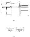
- Figure 3 shows a diagram of the relation between the line noise, the signal to noise ratio margin and the line rate.
- the abscissa axis represents time, and the relation between the line noise, the signal to noise ratio margin and the line rate are shown by the ordinate.
- the switch to a predetermined bit gain table is performed to reduce the rate.
- the adjacent pair enters a power control phase and the crosstalk decreases, i.e., the line noise decreases, so that the SNRM increases.
- the rate may be adjusted through the SRA to increase the line rate.
- the crosstalk greatly decreases, i.e., the line noise greatly decreases, so that the SNRM increases.
- the rate may be adjusted through the SRA to increase the line rate.
- a switch message is also defined.
- VDSL2 ITU-T G.993.2
- eoc embedded overhead channel
- OLR OLR command
- the command type field is (00000001) 2
- subscript 2 represents binary
- other fields are defined in the following tables.
- Type 1 has been used, and according to the embodiment of the present invention, Type 2 or Type 3 may be used.
- the length of the fields is set to 2 octets, and the contents of the second octets are respectively (as shown in the table):05 16 , 06 16 , where subscript 16 represents hex.
- Another message Type 4 may be defined, whose length is 2 octets, the content of the second octet being 07 16 . Therefore, the definitions in the current standard are not affected.
- the format of the response message corresponding to the switch message is as shown in the following table.
- the length of a message for granting the switch is 2 octets, where the second octet is 72 16 or 73 16 (corresponding to the message type).
- the length of a message for rejecting the switch is 3 octets, where the second octet is 82 16 or 83 16 (corresponding to the message type), and the third octet is the cause for rejecting (alternatively, if the cause is not needed, the length is 2 octets).
- a response Type 4 is defined and the length of a message for granting the switch is 2 octets, where the second octet is 73 16 , and the length of a message for rejecting the switch is 3 octets, where the second octet is 83 16 , and the third octet is the cause for rejecting (alternatively, if the cause is not needed, the length is 2 octets).
- the synchronization signal is based on the signal defined in G.993.2, i.e., the synchronization signal is represented by switches between all-0 and all-1 of synchronization symbols.
- the messages have more capacity, and thus are able to facilitate the communication between two parties.
- a switch request message Type 2 or Type 3 or Type 4 may be transmitted without acknowledgement, and then the transceiver executes the switch action upon receiving this message, and instructs the receiving end through synchronization symbols to execute the synchronous switch. If rejected, the synchronization message is not transmitted.
- the transmission and parsing process of the message content is avoided, thereby increasing the switch speed and reducing the error probability.
- two sets of parameters are calculated in advance in the training, where one set is a bit table and gain table obtained according to the current channel parameter (for example, channel noise), and another set is a conservative bit table and gain table obtained according to the virtual noise or experiential bit table calculating parameter. These two sets of parameters are saved in the first transceiver and the second transceiver at the same time.
- the transceiver uses the bit table and the gain table obtained according to the current channel parameter, called current bit table and gain table, and this bit table and gain table is dynamically adjusted with the change in the channel (for example, bit swapping).
- the solutions according to the embodiments of the present invention have the advantages of fast switch speed and high reliability.
- the above wideband noise decreases (for example, the user of a crosstalk source turns off the modem)
- the SNRM may be calculated according to the current channel parameter, and the frequency spectrum utilization may be increased by increasing the rate through the SRA.
- link drops may be avoided by responding to the feature of sudden increasing of the crosstalk.
- SRA failures are likely to occur because of response speed and errors in the parameter exchange process, thereby causing the re-training and interrupting the service.
- the following query-response mode may be adopted. Specifically, the line quality is determined according to the result of query-response. The method of obtaining the line quality through the query-response mode is described as follows.
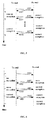
- Figure 4 shows the query message
- figure 4 (b) shows the response message. It is assumed that the first transceiver transmits the query message to the second transceiver.
- the second transceiver when the second transceiver does not correctly receive the query message from the first transceiver, the second transceiver does not respond.
- the first transceiver When the first transceiver does not correctly receive the response message from the receiving end, the first transceiver will continually re-transmit the query message identical to the previous one at a prescribed time point.
- a register may be provided in the first transceiver and the second transceiver, the bits of which respectively record receiving status of n consecutive messages.
- the registers in the first transceiver and the first transceiver are represented respectively with TM and RM. After initialization or after a bit table entry switch, the initial values of the TM and the RM should be zero.
- the first transceiver For the first transceiver, within the current time frame, the first transceiver writes '1' in the current bit of the TM if no valid response message is received within the prescribed time interval, and writes '0' if a valid response message is received within the prescribed time interval. Then, the first transceiver receives the response message within the next time frame, determines the next bit of the TM as the current bit, and writes '1' in the current bit of the TM if no valid response message is received within the prescribed time interval, and writes '0' if a valid response message is received within the prescribed time interval.
- the second transceiver For the second transceiver, within the current time frame, the second transceiver writes '1' in the current bit of the RM if no valid query message is received within the prescribed time interval, and writes '0' if a valid query message is received within the prescribed time interval; then, the second transceiver receives the query message within the next time frame, determines the next bit of the RM as the current bit, and writes '1' in the current bit of the RM if no valid query message is received within the prescribed time interval, and writes '0' if a valid query message is received within the prescribed time interval.
- the first transceiver when a predetermined number (i.e., switch threshold) of bits in the TM register are set to '1', a decision is made to perform the switch at a time agreed on between the first transceiver and the second transceiver, for example, to perform the switch of bit table and gain table at the tenth symbol of the next synchronization frame.
- a predetermined number i.e., switch threshold
- the synchronous switch of bit table may be implemented, to cope with various problems such as link drop caused by sudden increase of the line noise (for example, crosstalk).
- the same mechanism is adapted for the second transceiver in order to perform the switch of bit table.
- Figure 7 shows a case of query-response where the TM and the RM have 5 bits and the switch threshold is 3.
- the solid line represents that the present message transmission is correct, and the dashed line represents that the present message transmission is wrong.
- the first transceiver transmits a query message having a counter octet of 001 to the second transceiver, and upon receiving the query message; the second transceiver returns a response message having a counter octet of 002 to the first transceiver.
- the bits in the TM and the RM of the first transceiver and the second transceiver do not change, i.e., all are 0.
- the TM and the RM respectively shift by one bit circularly in a forward direction
- the first transceiver transmits a query message having a counter octet of 002 to the second transceiver
- the second transceiver still returns a response message having a counter octet of 002 to the first transceiver.
- the current bit (the last one bit as shown in the figure) in the TM and the RM of the first transceiver and the second transceiver are all set to 1.
- the TM and the RM respectively shift by one bit circularly in a forward direction
- the first transceiver transmits a query message having a counter octet of 002 to the second transceiver
- the second transceiver's receiving is correct
- the current bit in the RM of the second transceiver keeps to 0, and then the second transceiver returns a response message having a counter octet of 003 to the first transceiver. Because the first transceiver does not receive the response message within the prescribed time interval, the current bit in the TM of the first transceiver is set to 1.
- the number of '1's (switch threshold) in the TM of the first transceiver reaches to 3
- the first transceiver transmit a query message having a wrong counter octet to the second transceiver, so that the number of '1's in the RM of the second transceiver reaches to the switch threshold as soon as possible, in order to perform the switch of bit table at the tenth symbol of the next synchronization frame.
- the synchronous switch of bit table can be implemented, and the solutions according to the embodiments of the present invention have the advantages of fast switch speed and high reliability.
- the SNRM may be calculated according to the current channel parameter, and the frequency spectrum utilization can be increased by increasing the rate through the SRA, thus increasing the transmission speed.
- the switch of gain table may or may not be performed.
- a bit table and gain table are determined in advance, and the determined bit table and gain table are respectively saved in the first transceiver and the second transceiver.
- a very large wide band noise for example, crosstalk
- a fast switch from the current bit table and gain table to the previously determined bit table and gain table is performed by using a simple message or a query-response mechanism.
- the solutions according to the embodiments of the present invention have the advantages of fast switch speed and high reliability.
- the SNRM may be calculated according to the current channel parameter, and the frequency spectrum utilization may be increased by increasing the rate through the SRA.
Landscapes
- Engineering & Computer Science (AREA)
- Signal Processing (AREA)
- Computer Networks & Wireless Communication (AREA)
- Quality & Reliability (AREA)
- Telephonic Communication Services (AREA)
- Cable Transmission Systems, Equalization Of Radio And Reduction Of Echo (AREA)
- Mobile Radio Communication Systems (AREA)
- Communication Control (AREA)
Abstract
Description
- The present invention relates to a communication technique, especially to a method and a device for performing communication in digital subscriber line technology.
- After several years of development, ADSL (asymmetric digital subscriber line) technology has developed from the first generation to ADSL2 (second generation ADSL), ADSL2+ (ADSL2 with downlink bandwidth being extended) and more recent VDSL2 (second generation very high rate digital subscriber line). The frequency band being used is increasing gradually, and the bandwidth is also increasing gradually. The ADSL and ADSL2 employ a frequency spectrum below 1.1 MHz in downlink and are able to provide a maximum downlink rate of 8 Mbps, the ADSL2+ extends the downlink bandwidth to 2.2 MHz and is able to provide a maximum downlink rate of 24 Mbps, and the VDSL2 can even employ a frequency spectrum up to 30 MHz and is able to provide a maximum access rate of 100 Mbit/s which is symmetrical in uplink and downlink. The above digital subscriber line technologies are totally called as xDSL.
- Because the transmission medium for the xDSL is an unshielded twisted-pair, and electromagnetic coupling exists between different twisted-pairs, the signal transmitted on a twisted-pair may be transmitted to another twisted-pair through electromagnetic coupling to form a crosstalk. To reduce such a crosstalk, the twisted-pairs adopt different pitches, and the xDSL adopts differential signal transmission and reception, to counteract the common mode interference signal as far as possible by using the symmetry of twisted-pairs. However, in reality, the symmetry of twisted-pairs is relative and the crosstalk still exists. In addition, the interference signal in the ambient environment may also be coupled to the twisted-pairs, because the symmetry of twisted-pairs is limited and the interference signal can be converted into a differential mode signal to cause interference.
- The crosstalk between pairs may greatly affect the service. For example, when a
pair 1 is trained, its adjacent lines have no service, and a higher activate rate can be achieved with respect to a given signal to noise ratio margin. Hereafter, the adjacent lines also start to training, and signals emitted from these lines cause a crosstalk signal on thepair 1, which may result in a noise increase that may reach to ten and more dBs. At this time, the originally set signal to noise ratio margin of the pair 1 (generally of 6 dB) cannot ensure the operation at the original bit error rate and rate by the lines. At this time, the better case may result in an increased bit error rate, and the worse case may result in link break and re-training, causing a service interruption. This problem can be more serious in case of VDSL2. Because the VDSL2 means a higher frequency and a shorter line, and the remote crosstalk increases with the frequency and decreases with the increase of distance, the crosstalk has a greater influence. The ADSL2+ defines a fast training mode. Although the fast re-training may recover the connection within a minimum duration of 3 seconds, an influence to the service cannot be completely avoided. Moreover, some services such as voice over IP may require to re-connect due to problems such as link drop, and therefore, keeping a good communication connection quality (for example, no link drop) may be very important to service quality and user experience. - In the prior art, there are three kinds of solutions to solve the crosstalk caused by changing the adjacent line from unusable still state (in the silent state, there is no signal in the line) to normal use. The above three kinds of technical solutions will be respectively described in the following.
- Solution one, by increasing the target Signal to Noise Ratio (SNR) margin of the
pair 1, a larger signal to noise ratio margin is reserved when training thepair 1, so that when the crosstalk suddenly increases, the communication can still keep the target bit error rate as long as the increase does not reach to or exceed the target signal to noise ratio margin, and there is an enough margin to avoid the re-training. This solution has the benefits of simplicity and practicability, but also the deficiency that increasing the signal to noise ratio margin may a reduced rate that can be achieved on thepair 1. Moreover, because the crosstalk noise is generally not flat, that is to say, noise power spectrum densities at different frequency points are different, and the signal to noise ratio margin is a flat value such that substantially equal values are reserved as margins for signal to noise ratios of all the sub-channels, in view of a fact that the crosstalk is serious only in some frequency ranges, a too higher signal to noise ratio will waste the transmission capacity in the frequency bands where the crosstalk influence is very small. - Solution two is a seamless rate adaptation (SRA) solution. When the signal to noise ratio of the line reduces due to the crosstalk, the SRA solution ensure the signal to noise ratio margin by reducing the number of bits modulated on the sub-carriers being affected, so that the bit error rate is not higher that the target value. According to this solution the bit allocating can be adjusted automatically according to the noise distribution, so as to avoid the problem of solution one. However, because it is necessary in the SRA solution to calculate and update bit tables and gain tables for the sub-carriers (bit allocation tables and gain adjustment tables for the sub-carriers in case of multiple carrier communication. See ADSL or VDSL standard of ITU-T), the amount of the data is very large. Limited by transmission capability of the channel for transmitting the overhead, the solution has a lower response speed. However, the crosstalk from the adjacent lines suddenly increases at the moment of entering the training, and therefore the re-training may be performed due to consecutive failures, before completing the adjustment to the transceiver. Further, it is necessary in the SRA solution to transmit a lot of data (bit and gain table) between the receiving device and the transmitting device. However, the signal to noise ratio of the channel has reduced, and the process of updating the bit and gain tables may fail due to errors.
- Solution three, in the ITU-T G.993.2 standard (also called VDSL2), a concept of virtual noise (VN) is introduced, which is a noise obtained by shaping as required.
Figure 1 shows a relation between the virtual noise and the actual noise, where the dashed line represents a virtual noise variation curve and the solid line represents a noise variation curve. If such a virtual noise is used to calculate the signal to noise ratio and the bit load of each of the sub-carriers is calculated, a VN based line rate can be obtained. By setting an appropriate VN not lower than the maximal possible crosstalk noise in a basic bundled unit of the cable (for example, in case of VDSL, for a basic unit of 25 pairs, the VN is setting as not lower than the crosstalk generated when 24 pairs of lines are activated at the same time), thepair 1 will not suffer a re-training even if these pairs are trained after thepair 1 reaches the showtime (a term for special use in the standard, also called operating state)Moreover, because of adopting a shaped noise, enough margins are only reserved on the required sub-channels to avoiding the waste due to simply setting a flat target signal to noise ratio margin. However, this solution is still a conservative solution because of the following reason. For security, it is required to design the VN according to the maximal possible crosstalk noise, for example, the worst case of 1%. However, the crosstalk is not so bad actually in many cases, or is in the worst case only during a very short period, so that the solution always running in this conservative mode can still making the waste of channel capacity. - An object of the present invention is to provide a method and system for performing communication in digital subscriber line technology. The transmission rate may be adapted according to the noise change in the line, the anti-noise ability may be improved in order to avoid various problems (such as, link drop) caused by the large increase of line noise. The method and system are especially applicable to the case that the noise suddenly has a large increase in a short time. When the line noise is reduced, the line rate may be dynamically increased, thereby improving the transmission capacity.
- An embodiment of the present invention discloses a method of performing communication in digital subscriber line technology, including: acquiring a communication performance parameter; and using, by the first transceiver and the second transceiver, a predetermined communication rule to perform communication when the communication performance parameter reaches or exceeds a predetermined value.
- An embodiment of the present invention further discloses a transceiver in digital subscriber line technology, including: a receiving module configured to receive a signal from a subscriber line; a monitor module configured to acquire a communication performance parameter based on the received signal from the receiving module; and a processing module configured to perform a switch according to a predetermined communication rule based on the line quality parameter from the monitor module.
- An embodiment of the present invention further discloses a transceiver system in the digital subscriber line technology, including: a first transceiver and a second transceiver for communicating through a subscriber line.
- The first transceiver obtains a communication performance parameter, and the first transceiver and the second transceiver use a predetermined communication rule to perform communication when the communication performance parameter reaches or exceeds a predetermined value.
- According to the embodiments of the present invention, a bit table and a gain table are determined in advance and the determined bit table and gain table are respectively saved in the first transceiver and the second transceiver, or a calculation rule that can be understood and used by the first transceiver and the second transceiver is determined in advance. When a large wideband noise (for example, crosstalk) presents, a fast switch from the currently used bit table and gain table to the bit table and gain table determined in advance is performed by using a simple message or query-response mechanism, or a new bit table and gain table are calculated by using the currently used bit table and gain table according to the rule determined in advance and a fast switch to the new bit table and gain table is performed. Because it is not necessary to exchange the bit table and gain table between the first transceiver and the second transceiver, the solutions according to the embodiments of the present invention have the advantages of fast switch speed and high reliability. When the above wideband noise decreases (for example, the user of a crosstalk source turns off the modem), the SNRM may be calculated according to the current channel, and the frequency spectrum utilization may be increased by increasing the rate through the SRA.
-
-
Figure 1 shows an example about the relation between the virtual noise the actual noise; -
Figure 2 shows a schematic diagram of a receiving system according to an embodiment of the present invention; -
Figure 3 shows a schematic diagram of the relation between the line noise, the signal to noise ratio margin and the line rate according to one embodiment of the present invention; -
Figure 4 shows a schematic diagram of a query message and a response message according to one embodiment of the present invention; -
Figure 5 shows a query-response process between the first transceiver and the second transceiver according to one embodiment of the present invention; -
Figure 6 is a schematic diagram showing the case where a failure occurs in the query-response process between the first transceiver and the second transceiver according to one embodiment of the present invention; and -
Figure 7 shows a schematic diagram of performing a bit table switch by using the query-response process between the first transceiver and the second transceiver according to one embodiment of the present invention. - For ease in understanding and implementing the present invention by those skilled in the art, the embodiment of the present invention will be described in connection with the accompanying drawings.
- As shown in
figure 2 , one embodiment of the present invention discloses a transceiver system in the digital subscriber line technology, including: a first transceiver configured to acquire a communication performance parameter; and a second transceiver configured to acquire a communication performance parameter. When the communication performance parameter reaches or exceeds a predetermined value, the first transceiver communicates with a second transceiver according to a predetermined communication rule which is provided in the first transceiver, otherwise based on the parameters in a bit table and a gain table calculated according to the actual noise. When the communication performance parameter reaches or exceeds a predetermined value, the second transceiver communicates with the first transceiver according to a predetermined communication rule which is provided in the second transceiver, otherwise based on the parameters in a bit table and a gain table calculated according to the actual noise. - The configuration and the function of the first transceiver are the same as that of the second transceiver. One of them may be arranged at the office side, and another of them may be arranged at the subscriber side. The transceivers includes: a receiving module configured to receive a signal and a message from the peer transceiver; a monitor module configured to obtain a communication performance parameter from the acquiring, the communication performance parameter including signal to noise ratio, signal to noise ratio margin and bit error rate; a processing module configured to perform the switch of the predetermined communication rule according to the communication performance parameter from the monitor module and generate a switch message, and perform the switch for the predetermined communication rule according to the switch message, the predetermined communication rule including the bit table and/or the gain table; a transmitting module configured to transmit a signal and the switch message generated by the processing module to the peer transceiver.
- The processing module includes: a storage unit configured to store the bit tables and the gain tables respectively according to the two communication rules and the bit tables and the gain tables calculated according to the actual noise, and some configuration parameters such as switch threshold for triggering the bit tables and the gain tables (bi & gi) defined according to the bit error rate or the signal to noise ratio margin; a judgment unit configured to judge whether the communication performance parameter reaches or exceeds the predetermined value, and if the communication performance parameter reaches or exceeds the predetermined value, generate a switch message and transmitting the switch message to the peer end through the transmitting module, wait for a synchronization signal from the peer end, and initiate a switch unit if the synchronization signal is obtained from the peer end within a predetermined time; the switch unit configured to switch to the predetermined bit table and the predetermined gain table.
- The transceivers also includes: a seamless rate adaptor configured to calculate a bit table and a gain table according to the actual noise, and take them as a new communication rule to increase the rate when the noise decreases. The receiving module is also configured to receive the bit table and the gain table transmitted from the peer end and the transmitting module is also configured to transmit the bit table and the gain table to the peer end.
- The embodiments of the present invention also disclose a method of performing communication in the digital subscriber line technology, including: obtaining a communication performance parameter; judging whether the communication performance parameter reaches or exceeds the predetermined value, if the communication performance parameter reaches or exceeds the predetermined value, notifying the peer transceiver through a message and making the transceivers of both ends to using parameters in the predetermined bit table and the predetermined gain table to perform the communication, and if the communication performance parameter does not reach or exceed the predetermined value, making them to use parameters in the bit table and the gain table calculated according to the actual noise to perform the communication.
- To obtain the communication performance parameters, the monitor module continues to monitor the signal received by the receiving module, and obtains the communication performance parameters such as signal to noise ratio, signal to noise ratio margin and bit error rate from the received signal, so as to notify the peer transceiver when one or more of these parameters reach or exceed predetermined values. Therefore, the transceivers of both ends adopt parameters in the predetermined bit table and the predetermined gain table to perform the communication.
- Upon obtaining the communication performance parameter, the judgment module judges whether the communication performance parameter reaches or exceeds the predetermined value. If the communication performance parameter reaches or exceeds the predetermined value, the peer transceiver is notified through a message and the transceivers of both ends are instructed to use parameters in the predetermined bit table and the predetermined gain table to perform the communication. If the communication performance parameter does not reach or exceed the predetermined value, the transceivers of both ends are instructed to use parameters in the bit table and the gain table calculated according to the actual noise to perform the communication.
- To judge whether the communication performance parameter reaches or exceeds the predetermined value, a virtual noise or experiential bit table calculating parameter, a signal to noise ratio margin threshold and/or a bit error rate threshold may be pre-set in the first transceiver (assuming that the first transceiver is arranged at the office side) before the training. The experiential bit table calculating parameter is a bit number reduced from the bit number calculated according to the actual noise to provide the bit number of the signal to noise ratio margin on each tone (sub-frequency band), then the virtual noise or experiential bit table calculating parameter, the signal to noise ratio margin threshold and/or the bit error rate threshold as set are saved in the storage module of the first transceiver. In order to send the virtual noise or experiential bit table calculating parameter, the signal to noise ratio margin threshold and/or the bit error rate threshold to the second transceiver (assuming that the second transceiver are arranged at the subscriber side) through information interaction in the training process, and the second transceiver saves the virtual noise or experiential bit table calculating parameter, the signal to noise ratio margin threshold and/or the bit error rate threshold in the storage module. In the training, the processing module of the second transceiver calculates two sets of signal to noise ratio table, bit table and gain table respectively based on the preset virtual noise or experiential bit table calculating parameter and the actual noise: SNRvi, Bvi and Gvi, and SNRri, bri and Gri, and saves the SNRvi, Bvi and Gvi, and the SNRri, bri and Gri in the local storage module and transmits them to the first transceiver through information interaction, in order to save them in the storage module of the first transceiver. Then the first transceiver and the second transceiver implement the connection based on the SNRri, bri and Gri calculated according to the actual noise.
- The process of judging whether the communication performance parameter reaches or exceeds the predetermined value is described as follows. The first transceiver and/or the second transceiver compare the monitored signal to noise ratio, signal to noise ratio margin and bit error rate with the preset thresholds stored in their storage modules. Taking the monitoring of the signal to noise ratio margin as an example, when it is found that the signal to noise ratio margins of multiple sub-carriers (according to the power distribution of the crosstalk, there are many consecutive sub-carriers in most cases), for example, 10 sub-carriers, are lower than the preset thresholds, which indicates a case where the training of an adjacent pair causes a sudden increase of the crosstalk, the transceiver generates a switch request message and transmits the switch request message to the peer transceiver. Upon receiving the switch request message, the peer transceiver switches to the bit table and the gain table calculated based on the virtual noise or experiential bit table calculating parameter, and then returns a confirmation message and a synchronization message (it is also possible to only return a synchronization message). Upon receiving the confirmation message and the synchronization message, the transceiver switches to the bit table and the gain table calculated based on the virtual noise. Thus, the first transceiver and the second transceiver can perform the communication by using the bit table and the gain table calculated from the virtual noise.
- The predetermined bit table and the predetermined gain table may be obtained according to the preset virtual noise or may be an experiential bit table.
- The virtual noise may be the noise in case of the worst line crosstalk. Thus, in the training, in addition to obtaining a signal to noise ratio table SNRri, a bit table Bri and a gain table Gri according to the actual noise on the U-interface (an interface between the xDSL transceiver and the external twisted-pair), the first transceiver and the second transceiver also calculate another corresponding data (SNRvi, Bvi and Gvi) according to the preset virtual noise or experiential bit table calculating parameter. The signal to noise ratio table SNRri, the bit table Bri and the gain table Gri respectively represent the signal to noise ratio, the number of carried bits and the relative gain adjustment coefficient of each sub-carrier. (SNRvi, Bvi and Gvi) are respectively saved in the storage modules of the first transceiver and the second transceiver. When the transceiver detects that the signal to noise ratio SNRi and/or the signal to noise ratio margin SNRMi and/or the bit error rate BER reach or exceed a preset value due to the crosstalk generated by training the adjacent pair, the transceiver transmits a switch request message to the peer end transceiver, so that the peer end transceiver switches to the Bvi and the Gvi calculated according to the saved virtual noise or experiential bit table calculating parameter, and the synchronous switch between the first transceiver and the second transceiver is implemented through the switch synchronization signal.
- The experiential bit table may be obtained by experience, for example, according to experiential distribution of the crosstalk. By subtracting a corresponding bit number from the actual noise-based bit gain table Bri & Gri obtained according to the training result (the increase of signal to noise ratio margin caused by the subtracted bit number should be greater than or equal to the decrease of signal to noise ratio margin caused by the crosstalk), it is necessary to design the virtual noise and transmit it the peer end, thereby further simplifying the operations.
- Because the bit load and gain adjustment table calculated according to the virtual noise is a very conservative solution, although the signal to noise ratio margin and the bit error rate meet the requirement (usually reach or exceed the requirement), the resultant rate is lower than the value in case of actual noise. The line rate may be increased step-by-step according to the actual SNRri. Accordingly, a fast decreasing rate may be obtained to accommodate the sudden increase of noise, and to slowly increase the rate to accommodate the dynamic rate adjustment process with the noise being reduced. Because the line parameters in this fast switch process are calculated in advance, and saved in the first transceiver and the second transceiver, the switch can be implemented only through a simple message and a synchronization message when it is necessary to perform the switch. This is much faster and more reliable than the original SRA or BS, because the SRA or BS needs to transmit the updated bit table and gain table. In case of SRA or BS, a failure may occur in transmitting the bit table and the gain table due to the bit errors in the transmission process, if the channel is poor. The solution according to the embodiment of the present invention will not cause this problem, and when the line crosstalk noise decreases, the signal to noise ratio increases and the bit error rate decreases, so that a large amount of data required by the SRA can be transmitted.
- When entering the showtime, the signal to noise ratio table SNRri, the bit table Bri and the gain table Gri calculated according to the actual noise may act as transmission parameters, to achieve a higher transmission rate.
-
Figure 3 shows a diagram of the relation between the line noise, the signal to noise ratio margin and the line rate. As shown infigure 3 , the abscissa axis represents time, and the relation between the line noise, the signal to noise ratio margin and the line rate are shown by the ordinate. At time a, because the adjacent pair starts the training to greatly increase the line noise and sharply reduce the SNRM, according to the embodiment of the present invention, the switch to a predetermined bit gain table is performed to reduce the rate. During the period from time b to time c, when the training of the adjacent pair completes, the adjacent pair enters a power control phase and the crosstalk decreases, i.e., the line noise decreases, so that the SNRM increases. Thus, according to the embodiment of the present invention, the rate may be adjusted through the SRA to increase the line rate. During the period from time d to time e, when the subscriber of the adjacent pair turns off the modem, the crosstalk greatly decreases, i.e., the line noise greatly decreases, so that the SNRM increases. Thus, according to the embodiment of the present invention, the rate may be adjusted through the SRA to increase the line rate. - To implement the embodiments of the present invention, a switch message is also defined. In the standard for VDSL2 (ITU-T G.993.2), an eoc (embedded overhead channel) message for an OLR command is defined. The command type field is (00000001)2,
subscript 2 represents binary, and other fields are defined in the following tables.Name Length (octets) Octet number Content Request Type 1 5 + 4 × Nf (Nf ≤ 128) 2 0416 (NOTE) 3 to 4 2 octets for the number of sub-carriers Nf to be modified 5 to 4 + 4 × N f4 × Nf octets describing the sub-carrier parameter field for each sub-carrier 5+4× N f1 octet for SC Request Type 2 For further study 2 0516 (NOTE) All others Reserved by the ITU- T Request Type 3 For further study 2 0616 (NOTE) All others Reserved by the ITU-T NOTE - All other values for octet number 2 are reserved by the ITU-TTable 11-7/G.993.2 - Reason codes for OLR responses Reason Octet value Applicable to Defer Type 1Applicable to Reject Type 2Applicable to Reject Type 3Busy 0116 X X X Invalid parameters 0216 X X X - According to the above table,
Type 1 has been used, and according to the embodiment of the present invention,Type 2 orType 3 may be used. The length of the fields is set to 2 octets, and the contents of the second octets are respectively (as shown in the table):0516, 0616, where subscript 16 represents hex. Anothermessage Type 4 may be defined, whose length is 2 octets, the content of the second octet being 0716. Therefore, the definitions in the current standard are not affected. As such, the format of the response message corresponding to the switch message is as shown in the following table.Name Length (octets) Octet number Content Defer Type 1Request 3 2 8116 (NOTE) 3 1 octet for reason code (Table 11-7) Reject Type 2Request 3 2 8216 (NOTE) 3 1 octet for reason code (Table 11-7) Reject Type 3Request 3 2 8316 (NOTE) 3 1 octet for reason code (Table 11-7) IACK 3 2 8B16 (NOTE) 3 1 octet for SC NOTE - All other values for octet number 2 are reserved by the ITU-T - Therefore, if the existing
Type 2 orType 3 is directly adopted, corresponding message fields are modified. The length of a message for granting the switch is 2 octets, where the second octet is 7216 or 7316 (corresponding to the message type). The length of a message for rejecting the switch is 3 octets, where the second octet is 8216 or 8316 (corresponding to the message type), and the third octet is the cause for rejecting (alternatively, if the cause is not needed, the length is 2 octets). The length in case of newly definedType 4, aresponse Type 4 is defined and the length of a message for granting the switch is 2 octets, where the second octet is 7316, and the length of a message for rejecting the switch is 3 octets, where the second octet is 8316, and the third octet is the cause for rejecting (alternatively, if the cause is not needed, the length is 2 octets). The synchronization signal is based on the signal defined in G.993.2, i.e., the synchronization signal is represented by switches between all-0 and all-1 of synchronization symbols. - In the above method, the messages have more capacity, and thus are able to facilitate the communication between two parties. To increase the switch speed, a switch
request message Type 2 orType 3 orType 4 may be transmitted without acknowledgement, and then the transceiver executes the switch action upon receiving this message, and instructs the receiving end through synchronization symbols to execute the synchronous switch. If rejected, the synchronization message is not transmitted. Thus, the transmission and parsing process of the message content is avoided, thereby increasing the switch speed and reducing the error probability. - According to the above embodiment, two sets of parameters are calculated in advance in the training, where one set is a bit table and gain table obtained according to the current channel parameter (for example, channel noise), and another set is a conservative bit table and gain table obtained according to the virtual noise or experiential bit table calculating parameter. These two sets of parameters are saved in the first transceiver and the second transceiver at the same time. When the training is completed, the transceiver uses the bit table and the gain table obtained according to the current channel parameter, called current bit table and gain table, and this bit table and gain table is dynamically adjusted with the change in the channel (for example, bit swapping). When a very large wide band noise (for example, crosstalk) presents, a fast switch from the current bit table and gain table to the bit table and gain table corresponding to the virtual noise is performed by using a simple message. Because it is not necessary to exchange the bit table and gain table and only a simple message is exchanged, compared with the bit exchange, the solutions according to the embodiments of the present invention have the advantages of fast switch speed and high reliability. When the above wideband noise decreases (for example, the user of a crosstalk source turns off the modem), the SNRM may be calculated according to the current channel parameter, and the frequency spectrum utilization may be increased by increasing the rate through the SRA.
- In addition, because the switch speed in the solutions according to the embodiment of the present invention is fast, link drops may be avoided by responding to the feature of sudden increasing of the crosstalk. In case of SRA, failures are likely to occur because of response speed and errors in the parameter exchange process, thereby causing the re-training and interrupting the service.
- To obtain the communication performance parameter, the following query-response mode may be adopted. Specifically, the line quality is determined according to the result of query-response. The method of obtaining the line quality through the query-response mode is described as follows.
- As shown in
figure 4 , a query message and a response message are constructed.Figure 4 (a) shows the query message, andfigure 4 (b) shows the response message. It is assumed that the first transceiver transmits the query message to the second transceiver. - When the counter in the query message received by the second transceiver is X (X falls within the range of 0 - 255), the message is responded immediately, and the counter octet in the responded response message should be
X+ 1. If an overflow occurs, the value of the counter octet is set to zero. When the first transceiver receives the response message and the content of the counter octet is valid, a query message is transmitted after a time interval (T), and the content of the counter octet is that of the valid counter octet received from the second transceiver. The further course is similar to the above.Figure 5 shows a query-response process between the first transceiver and the second transceiver. - As shown in
figure 6 , when the second transceiver does not correctly receive the query message from the first transceiver, the second transceiver does not respond. When the first transceiver does not correctly receive the response message from the receiving end, the first transceiver will continually re-transmit the query message identical to the previous one at a prescribed time point. - To record the result of query-response, a register may be provided in the first transceiver and the second transceiver, the bits of which respectively record receiving status of n consecutive messages. To facilitate the description, the registers in the first transceiver and the first transceiver are represented respectively with TM and RM. After initialization or after a bit table entry switch, the initial values of the TM and the RM should be zero.
- For the first transceiver, within the current time frame, the first transceiver writes '1' in the current bit of the TM if no valid response message is received within the prescribed time interval, and writes '0' if a valid response message is received within the prescribed time interval. Then, the first transceiver receives the response message within the next time frame, determines the next bit of the TM as the current bit, and writes '1' in the current bit of the TM if no valid response message is received within the prescribed time interval, and writes '0' if a valid response message is received within the prescribed time interval.
- For the second transceiver, within the current time frame, the second transceiver writes '1' in the current bit of the RM if no valid query message is received within the prescribed time interval, and writes '0' if a valid query message is received within the prescribed time interval; then, the second transceiver receives the query message within the next time frame, determines the next bit of the RM as the current bit, and writes '1' in the current bit of the RM if no valid query message is received within the prescribed time interval, and writes '0' if a valid query message is received within the prescribed time interval.
- In the first transceiver, when a predetermined number (i.e., switch threshold) of bits in the TM register are set to '1', a decision is made to perform the switch at a time agreed on between the first transceiver and the second transceiver, for example, to perform the switch of bit table and gain table at the tenth symbol of the next synchronization frame. To ensure the synchronous switch, keep transmitting invalid data after the switch is decided, so that the second transceiver reaches the switch condition as soon as possible, and thus the switch of bit table and gain table is performed at the tenth symbol of the next synchronization frame. Thus, without the need to transmit the switch message between the first transceiver and the second transceiver, the synchronous switch of bit table may be implemented, to cope with various problems such as link drop caused by sudden increase of the line noise (for example, crosstalk). The same mechanism is adapted for the second transceiver in order to perform the switch of bit table.
-
Figure 7 shows a case of query-response where the TM and the RM have 5 bits and the switch threshold is 3. As shown infigure 7 , the solid line represents that the present message transmission is correct, and the dashed line represents that the present message transmission is wrong. In the first time frame, the first transceiver transmits a query message having a counter octet of 001 to the second transceiver, and upon receiving the query message; the second transceiver returns a response message having a counter octet of 002 to the first transceiver. At this time, the bits in the TM and the RM of the first transceiver and the second transceiver do not change, i.e., all are 0. In the second time frame, the TM and the RM respectively shift by one bit circularly in a forward direction, the first transceiver transmits a query message having a counter octet of 002 to the second transceiver, and not receiving the query message, the second transceiver still returns a response message having a counter octet of 002 to the first transceiver. At this time, the current bit (the last one bit as shown in the figure) in the TM and the RM of the first transceiver and the second transceiver are all set to 1. In the third time frame, the TM and the RM respectively shift by one bit circularly in a forward direction, the first transceiver transmits a query message having a counter octet of 002 to the second transceiver, and upon receiving the query message, the second transceiver's receiving is correct, the current bit in the RM of the second transceiver keeps to 0, and then the second transceiver returns a response message having a counter octet of 003 to the first transceiver. Because the first transceiver does not receive the response message within the prescribed time interval, the current bit in the TM of the first transceiver is set to 1. Similar to these, when reaching to the 7th time frame, the number of '1's (switch threshold) in the TM of the first transceiver reaches to 3, and from the 8th time frame, the first transceiver transmit a query message having a wrong counter octet to the second transceiver, so that the number of '1's in the RM of the second transceiver reaches to the switch threshold as soon as possible, in order to perform the switch of bit table at the tenth symbol of the next synchronization frame. Because it is not necessary to re-transmit the message between the first transceiver and the second transceiver, the synchronous switch of bit table can be implemented, and the solutions according to the embodiments of the present invention have the advantages of fast switch speed and high reliability. When the above wideband noise decreases (for example, the user of a crosstalk source turns off the modem), the SNRM may be calculated according to the current channel parameter, and the frequency spectrum utilization can be increased by increasing the rate through the SRA, thus increasing the transmission speed. - When performing the switch of bit table, the switch of gain table may or may not be performed.
- In summary, a bit table and gain table are determined in advance, and the determined bit table and gain table are respectively saved in the first transceiver and the second transceiver. When a very large wide band noise (for example, crosstalk) presents, a fast switch from the current bit table and gain table to the previously determined bit table and gain table is performed by using a simple message or a query-response mechanism. Because it is not necessary to exchange the bit table and gain table between the first transceiver and the second transceiver, the solutions according to the embodiments of the present invention have the advantages of fast switch speed and high reliability. When the above wideband noise decreases (for example, the user of a crosstalk source turns off the modem), the SNRM may be calculated according to the current channel parameter, and the frequency spectrum utilization may be increased by increasing the rate through the SRA.
- Although the present invention has been described in connection with the embodiments, those skilled in the art know that, there can be many variations and changes to the present invention without departing from the spirit and substance of the present invention, and the scope of the present invention is defined by the appended claims.
- Further embodiments of the present invention are provided in the following. It should be noted that the numbering used in the following section does not necessarily need to comply with the numbering used in the previous sections.
-
Embodiment 1. A method of performing communication in digital subscriber line technology, characterized by comprising:- obtaining a communication performance parameter;
- using, by a first transceiver and a second transceiver, a predetermined communication rule to perform communication when the communication performance parameter reaches or exceeds a predetermined value.
-
Embodiment 2. The method according toembodiment 1, characterized in that:- the predetermined communication rule is respectively pre-set in the first transceiver and the second transceiver, or is obtained during communication according to a predetermined method of calculating a communication rule respectively set in the first transceiver and the second transceiver.
-
Embodiment 3. The method according toembodiment 1, characterized in that, the obtaining a communication performance parameter comprises: monitoring, by the first transceiver and/or the second transceiver, the communication performance parameter, the communication performance parameter comprising one of signal to noise ratio, signal to noise ratio margin and bit error rate, or any combination of signal to noise ratio, signal to noise ratio margin and bit error rate. -
Embodiment 4. The method according toembodiment 3, characterized in that, the using, by the first transceiver and the second transceiver, a predetermined communication rule to perform communication when the communication performance parameter reaches or exceeds a predetermined value comprises:- when any parameter combination of signal to noise ratio, signal to noise ratio margin, bit error rate monitored by the first transceiver and/or the second transceiver reaches or exceeds the predetermined value, transmitting, by the first transceiver and/or the second transceiver, a switch request message to the second transceiver and/or the first transceiver, so that the first transceiver and the second transceiver adopt the predetermined communication rule to perform the communication, the switch request message being the message of an embedded an overhead channel.
-
Embodiment 5. The method according toembodiment 4, characterized in that, the using, by the first transceiver and the second transceiver, a predetermined communication rule to perform communication when the communication performance parameter reaches or exceeds a predetermined value comprises: when the second transceiver and/or the first transceiver receive the switch request message from the first transceiver and/or the second transceiver, transmitting, by the second transceiver and/or the first transceiver, a response message to the first transceiver and/or the second transceiver through an embedded overhead channel, wherein the content of the response message comprises granting the switch and rejecting the switch, and when the content of the response message is rejecting the switch, the response message further comprises the cause for rejecting the switch. -
Embodiment 6. The method according toembodiment 4, characterized in that, the using, by the first transceiver and the second transceiver, a predetermined communication rule to perform communication when the communication performance parameter reaches or exceeds a predetermined value comprises: adopting synchronization symbols to perform the synchronous switch of the first transceiver and/or the second transceiver, wherein the synchronous switch is performed by a transition from all-0 to all-1 of the information carried by the synchronization symbols, or by a reverse transition. -
Embodiment 7. The method according toembodiment 1, characterized in that, the obtaining a communication performance parameter comprises obtaining the communication performance parameter through a query-response mechanism. -
Embodiment 8. The method according toembodiment 7, characterized in that, the obtaining the communication performance parameter through a query-response mechanism comprises:- transmitting, by the first transceiver/the second transceiver, a query message at a time frame interval, and returning, by the second transceiver/the first transceiver, a response message to the first transceiver/the second transceiver at a time frame interval; and
- determining, by the first transceiver/the second transceiver the communication performance parameter according to the receiving of the response/query message.
- Embodiment 9. The method according to
claim 8, characterized in that, determining, by the first transceiver/the second transceiver, the communication performance parameter according to the receiving of the response/query message comprises:- writing 1 on a current location in a circular register of the second transceiver/the first transceiver when the second transceiver/the first transceiver does not receive the query message correctly transmitted by the first transceiver/the second transceiver within a predetermined time interval, and writing 0 on the current location in the circular register of the second transceiver/the first transceiver when the second transceiver/the first transceiver receives the query message correctly transmitted by the first transceiver/the second transceiver within the predetermined time interval;
- writing 1 on the current location in the circular register of the first transceiver/the second transceiver when the first transceiver/the second transceiver does not receive the response message correctly returned by the second transceiver/the first transceiver within a predetermined time interval, and writing 0 on the current location in the circular register of the first transceiver/the second transceiver when the first transceiver/the second transceiver receives the response message correctly returned by the second transceiver/the first transceiver within the predetermined time interval;
- circularly shifting the circular register of the first transceiver/the second transceiver by one bit in a forward direction; and
- counting, by the first transceiver/the second transceiver, the number of '1's in the circular register until the number of '1's in the circular register reaches to a switch threshold, and in case that the number of '1's in the circular register does not reach to the switch threshold, returning to the step where the first transceiver/the second transceiver transmits a query message to the second transceiver/the first transceiver at a time frame interval, and the second transceiver/the first transceiver returns a response message to the first transceiver/the second transceiver at a time frame interval.
-
Embodiment 10. The method according toembodiment 7, characterized in that, the using, by the first transceiver and the second transceiver, a predetermined communication rule to perform communication when the communication performance parameter reaches or exceeds a predetermined value comprises:- using, by the first transceiver and/or the second transceiver, the parameter in a predetermined bit table to perform communication at a predetermined time when the communication performance parameter obtained by the first transceiver and/or the second transceiver reaches or exceeds the predetermined value.
- Embodiment 11. The method according to
embodiment 10, characterized in that, the predetermined time is the tenth symbol of the next synchronization frame. - Embodiment 12. The method according to one of
embodiments 1 to 11, characterized in that, the predetermined communication rule comprises: a predetermined bit table and/or gain table. - Embodiment 13. The method according to embodiment 12, characterized in that, the predetermined bit table is a bit table or experiential bit table calculated based on a virtual noise.
- Embodiment 14. The method according to one of
embodiments 1 to 11, characterized by further comprising:- adopting, by the first transceiver and the second transceiver the bit table and/or gain table calculated based on the actual noise to perform communication before adopting the predetermined bit table and/or gain table;
- adopting the bit table adjusted based on a seamless rate adaptation method to perform communication after adopting the predetermined bit table and/or gain table to perform communication.
- Embodiment 15. A transceiver in digital subscriber line technology, characterized by comprising:
- a receiving module configured to receive a signal from a subscriber line;
- a monitor configured to obtain a communication performance parameter based on the received signal from the receiving module; and
- a processing module configured to perform a switch of a predetermined communication rule based on the line quality parameter from the monitor.
- Embodiment 16. The transceiver according to embodiment 15, characterized in that, the processing module comprises:
- a storage unit configured to store the predetermined communication rule;
- a judgment unit configured to judge whether the communication performance parameter reaches or exceeds the predetermined value, and if the communication performance parameter reaches or exceeds the predetermined value, activate a switch unit; and
- the switch unit configured to switch to the predetermined communication rule.
- Embodiment 17. The transceiver according to embodiment 15, characterized by further comprising: a seamless rate configured to calculate the bit table and gain table according to the current actual noise.
- Embodiment 18. The transceiver according to embodiment 17, characterized in that, the receiving module is also configured to receive the bit table and the gain table transmitted from the peer end and the transmitting module is also configured to transmit the bit table and gain table to the peer end.
- Embodiment 19. A transceiver system in digital subscriber line technology, comprising a first transceiver and a second transceiver communicating through a subscriber line, characterized in that,
the first transceiver obtains a communication performance parameter, the first transceiver and the second transceiver use a predetermined communication rule to perform communication when the communication performance parameter reaches or exceeds a predetermined value. - Embodiment 20. The transceiver system according to embodiment 19, characterized in that, the first transceiver and the second transceiver respectively comprises:
- a receiving module for receiving a signal from the subscriber line;
- a monitor for obtaining the communication performance parameter based on the received signal from the receiving module;
- a processing module for performing the switch of predetermined communication rule based on the line quality parameter from the monitor, the predetermined communication rule being saved locally.
Claims (10)
- A communication method for a digital subscriber line system comprising a first transceiver and a second transceiver which are connected each other, comprising:obtaining, at a first transceiver, a communication performance parameter;calculating a first table including a parameter of bit allocation for sub-carriers in a multiple carrier communication;when the communication performance parameter reaches or exceeds the predetermined value, transmitting, from the first transceiver to the second transceiver, a switch message for requesting the second transceiver to switch to a second table including a parameter of bit allocation for sub-carriers, wherein the second table is calculated at the second transceiver based on a calculation rule to keep the parameter of bit allocation for sub-carriers within the second table as same as the parameter of bit allocation for sub-carriers within the first table calculated at the first transceiver;from a certain symbol, communicating at the first transceiver with the second transceiver using the first table at the first transceiver to implement synchronous switch;wherein the parameter of bit allocation within the first table is calculated at the first transceiver by subtracting a corresponding bit number from a current table including a parameter of bit allocation for sub-carriers.
- The method according to claim 1, wherein the certain symbol is nth symbol in a time frame, n indicating a symbol count.
- The method according to claim 1 or 2, wherein the communication performance parameter comprises at least one of a signal to noise ratio, a signal to noise ratio margin and a bit error rate.
- The method according to claim 1 or 3, wherein the parameter of bit allocation for sub-carriers within the first table is calculated at the first transceiver after the communication performance parameter is determined to reach or exceed the predetermined value.
- The method according to claim 1 or 3, wherein the parameter of bit allocation for sub-carriers within the first table is calculated and stored at the first transceiver before the communication performance parameter is determined to reach or exceed the predetermined value.
- A transceiver in a digital subscriber line system, comprising:a receiving module configured to receive a signal from a subscriber line;a monitor module coupled to the receiving module and configured to obtain a communication performance parameter;a processing module coupled to the monitor module and configured to calculate a first table including a parameter of bit allocation for sub-carriers in a multiple carrier communication, and generate a switch message for requesting an opposite transceiver to switch to a second table including a parameter of bit allocation for sub-carriers when the communication performance parameter reaches or exceeds a predetermined value, and execute a synchronous switch to the first table from a certain symbol, wherein the second table is calculated at the opposite transceiver based on a calculation rule to keep the parameter of bit allocation for sub-carriers within the second table as same as the parameter of bit allocation for sub-carriers within the first table calculated at the transceiver;a transmitting module coupled to the processing module and configured to transmit the switch message through the subscriber line to the opposite transceiver;wherein the parameter of bit allocation within the first table is calculated by subtracting a corresponding bit number from a current table including a parameter of bit allocation for sub-carriers.
- The transceiver according to claim 6, wherein the certain symbol is nth symbol in the time frame, n indicating a symbol count.
- The transceiver according to claim 6 or 7, wherein the communication performance parameter comprises at least one of a signal to noise ratio, a signal to noise ratio margin and a bit error rate.
- The transceiver according to claim 6 or 8, wherein the parameter of bit allocation for sub-carriers within the first table is calculated after the communication performance parameter is determined to reach or exceed the predetermined value.
- The transceiver according to claim 6 or 8, wherein the parameter of bit allocation for sub-carriers within the first table is calculated and stored at the transceiver before the communication performance parameter is determined to reach or exceed the predetermined value.
Priority Applications (1)
| Application Number | Priority Date | Filing Date | Title |
|---|---|---|---|
| EP18199993.9A EP3462625B1 (en) | 2006-04-13 | 2007-01-18 | A method and device for performing communication in digital subscriber line technology |
Applications Claiming Priority (4)
| Application Number | Priority Date | Filing Date | Title |
|---|---|---|---|
| CN2006100724390A CN101056342B (en) | 2006-04-13 | 2006-04-13 | A method and device for communication in the digital user line technology |
| EP14175175.0A EP2816732B1 (en) | 2006-04-13 | 2007-01-18 | A method and device for performing communication in digital subscriber line technology |
| PCT/CN2007/000196 WO2007118388A1 (en) | 2006-04-13 | 2007-01-18 | A method and device for performing communication in digital subscriber line technology |
| EP07702128.5A EP2009803B1 (en) | 2006-04-13 | 2007-01-18 | A method and device for performing communication in digital subscriber line technology |
Related Parent Applications (3)
| Application Number | Title | Priority Date | Filing Date |
|---|---|---|---|
| EP14175175.0A Division-Into EP2816732B1 (en) | 2006-04-13 | 2007-01-18 | A method and device for performing communication in digital subscriber line technology |
| EP14175175.0A Division EP2816732B1 (en) | 2006-04-13 | 2007-01-18 | A method and device for performing communication in digital subscriber line technology |
| EP07702128.5A Division EP2009803B1 (en) | 2006-04-13 | 2007-01-18 | A method and device for performing communication in digital subscriber line technology |
Related Child Applications (2)
| Application Number | Title | Priority Date | Filing Date |
|---|---|---|---|
| EP18199993.9A Division EP3462625B1 (en) | 2006-04-13 | 2007-01-18 | A method and device for performing communication in digital subscriber line technology |
| EP18199993.9A Division-Into EP3462625B1 (en) | 2006-04-13 | 2007-01-18 | A method and device for performing communication in digital subscriber line technology |
Publications (2)
| Publication Number | Publication Date |
|---|---|
| EP3038264A1 true EP3038264A1 (en) | 2016-06-29 |
| EP3038264B1 EP3038264B1 (en) | 2018-12-26 |
Family
ID=38609049
Family Applications (4)
| Application Number | Title | Priority Date | Filing Date |
|---|---|---|---|
| EP14175175.0A Active EP2816732B1 (en) | 2006-04-13 | 2007-01-18 | A method and device for performing communication in digital subscriber line technology |
| EP18199993.9A Active EP3462625B1 (en) | 2006-04-13 | 2007-01-18 | A method and device for performing communication in digital subscriber line technology |
| EP07702128.5A Active EP2009803B1 (en) | 2006-04-13 | 2007-01-18 | A method and device for performing communication in digital subscriber line technology |
| EP16152341.0A Active EP3038264B1 (en) | 2006-04-13 | 2007-01-18 | A method and device for performing communication in digital subscriber line technology |
Family Applications Before (3)
| Application Number | Title | Priority Date | Filing Date |
|---|---|---|---|
| EP14175175.0A Active EP2816732B1 (en) | 2006-04-13 | 2007-01-18 | A method and device for performing communication in digital subscriber line technology |
| EP18199993.9A Active EP3462625B1 (en) | 2006-04-13 | 2007-01-18 | A method and device for performing communication in digital subscriber line technology |
| EP07702128.5A Active EP2009803B1 (en) | 2006-04-13 | 2007-01-18 | A method and device for performing communication in digital subscriber line technology |
Country Status (9)
| Country | Link |
|---|---|
| US (3) | US8213488B2 (en) |
| EP (4) | EP2816732B1 (en) |
| CN (1) | CN101056342B (en) |
| AU (1) | AU2007240059B2 (en) |
| ES (1) | ES2533008T3 (en) |
| IN (1) | IN266813B (en) |
| PT (1) | PT2009803E (en) |
| RU (1) | RU2415510C2 (en) |
| WO (1) | WO2007118388A1 (en) |
Families Citing this family (18)
| Publication number | Priority date | Publication date | Assignee | Title |
|---|---|---|---|---|
| US7881403B2 (en) * | 2006-10-10 | 2011-02-01 | Futurewei Technologies, Inc. | System for realizing emergency rate adjustment |
| CN101272160B (en) * | 2007-03-20 | 2013-06-05 | 华为技术有限公司 | Method and device for confirming DSL reference virtual noise, configuration method and system |
| CN101048034A (en) | 2007-04-30 | 2007-10-03 | 华为技术有限公司 | Circuitboard interconnection system, connector component, circuit board and circuit board processing method |
| US8193915B2 (en) * | 2008-03-06 | 2012-06-05 | GM Global Technology Operations LLC | Multiple transceiver synchronous communication system |
| US8238450B2 (en) * | 2009-01-30 | 2012-08-07 | Futurewei Technologies Inc. | Dynamic transmitter noise level adjustment for digital subscriber line systems |
| US8406416B2 (en) * | 2009-04-06 | 2013-03-26 | Futurewei Technologies, Inc. | Configuring virtual noise parameters of very high-speed digital subscriber line |
| US8665897B2 (en) * | 2009-10-26 | 2014-03-04 | Adc Dsl Systems, Inc. | Systems and methods for high-speed digital subscriber line software download |
| PL2341654T3 (en) * | 2009-12-30 | 2017-06-30 | Lantiq Deutschland Gmbh | Bit allocation in a multicarrier system |
| US8917863B2 (en) * | 2010-03-05 | 2014-12-23 | Nokia Siemens Networks Oy | Method and device for data processing in a digital subscriber line environment |
| EP2866353B1 (en) * | 2013-10-22 | 2016-08-10 | Alcatel Lucent | Orderly leaving within a vectoring group |
| US10237125B2 (en) | 2014-03-31 | 2019-03-19 | British Telecommunications Public Limited Company | Dynamic line management system |
| US8885759B1 (en) * | 2014-06-10 | 2014-11-11 | Fahad S H Z Alkhaled | (Nx2)-channel bit communication system |
| CN105491652B (en) * | 2014-09-15 | 2019-07-12 | 中兴通讯股份有限公司 | The method of adjustment and device of gain-state |
| JP6443899B2 (en) | 2015-01-25 | 2018-12-26 | ヴァレンス セミコンダクター リミテッド | High-speed adaptive mode conversion digital canceller |
| US10256920B2 (en) | 2015-01-25 | 2019-04-09 | Valens Semiconductor Ltd. | Mode-conversion digital canceller for high bandwidth differential signaling |
| US10171182B2 (en) | 2015-01-25 | 2019-01-01 | Valens Semiconductor Ltd. | Sending known data to support fast convergence |
| TWI619359B (en) * | 2016-01-12 | 2018-03-21 | 智易科技股份有限公司 | Method for automatically removing crosstalk and an apparatus thereof |
| US20170357774A1 (en) * | 2016-06-08 | 2017-12-14 | David FIGG | Automated prescription communication system and method |
Citations (2)
| Publication number | Priority date | Publication date | Assignee | Title |
|---|---|---|---|---|
| WO2000054473A1 (en) * | 1999-03-12 | 2000-09-14 | Aware, Inc. | Seamless rate adaptive multicarrier modulation system and protocols |
| US20020137467A1 (en) * | 2001-01-16 | 2002-09-26 | Tzannes Marcos C. | Fast initialization using seamless rate adaptation |
Family Cites Families (14)
| Publication number | Priority date | Publication date | Assignee | Title |
|---|---|---|---|---|
| EP0551705A3 (en) * | 1992-01-15 | 1993-08-18 | Ericsson Ge Mobile Communications Inc. | Method for subbandcoding using synthetic filler signals for non transmitted subbands |
| US6072779A (en) * | 1997-06-12 | 2000-06-06 | Aware, Inc. | Adaptive allocation for variable bandwidth multicarrier communication |
| ES2337110T3 (en) * | 1997-10-10 | 2010-04-20 | Daphimo Co. B.V., Llc | MULTIPORTING MODEM WITHOUT DIVIDER. |
| US20030026282A1 (en) * | 1998-01-16 | 2003-02-06 | Aware, Inc. | Splitterless multicarrier modem |
| US6829307B1 (en) * | 1999-02-24 | 2004-12-07 | The Board Of Trustees Of Leland Stanford Junior University | Express bit swapping in a multicarrier transmission system |
| EP2267914A3 (en) * | 2000-01-07 | 2012-09-26 | Aware, Inc. | Systems and methods for loop length and bridged tap length determination of a transmission line |
| US6985516B1 (en) | 2000-11-27 | 2006-01-10 | Qualcomm Incorporated | Method and apparatus for processing a received signal in a communications system |
| FI110734B (en) | 2001-03-16 | 2003-03-14 | Nokia Corp | Channel codec test loops |
| WO2003043213A1 (en) | 2001-11-09 | 2003-05-22 | Globespan Virata, Inc. | System and method for initiating communication between transceivers |
| FI20040294A0 (en) * | 2004-02-25 | 2004-02-25 | Nokia Corp | Method for selecting transmission channel parameters, radio systems, controls, terminal and base station |
| JP2005277549A (en) * | 2004-03-23 | 2005-10-06 | Nec Corp | Mobile terminal, and reception decision method by mobile terminal |
| EP1605655A3 (en) | 2004-06-07 | 2008-02-27 | Broadcom Corporation | Upstream power cutback |
| US7738543B2 (en) * | 2006-06-05 | 2010-06-15 | Lantiq Deutschland Gmbh | Methods and systems for determining communication parameters |
| US7720136B2 (en) * | 2006-12-26 | 2010-05-18 | Provigent Ltd | Adaptive coding and modulation based on link performance prediction |
-
2006
- 2006-04-13 CN CN2006100724390A patent/CN101056342B/en active Active
-
2007
- 2007-01-18 AU AU2007240059A patent/AU2007240059B2/en active Active
- 2007-01-18 IN IN4478KON2008 patent/IN266813B/en unknown
- 2007-01-18 RU RU2008143661/09A patent/RU2415510C2/en active
- 2007-01-18 EP EP14175175.0A patent/EP2816732B1/en active Active
- 2007-01-18 WO PCT/CN2007/000196 patent/WO2007118388A1/en active Application Filing
- 2007-01-18 EP EP18199993.9A patent/EP3462625B1/en active Active
- 2007-01-18 ES ES07702128.5T patent/ES2533008T3/en active Active
- 2007-01-18 EP EP07702128.5A patent/EP2009803B1/en active Active
- 2007-01-18 EP EP16152341.0A patent/EP3038264B1/en active Active
- 2007-01-18 PT PT07702128T patent/PT2009803E/en unknown
-
2008
- 2008-10-10 US US12/249,659 patent/US8213488B2/en active Active
-
2012
- 2012-06-07 US US13/491,234 patent/US8599907B2/en active Active
-
2013
- 2013-10-29 US US14/065,913 patent/US8867593B2/en active Active
Patent Citations (4)
| Publication number | Priority date | Publication date | Assignee | Title |
|---|---|---|---|---|
| WO2000054473A1 (en) * | 1999-03-12 | 2000-09-14 | Aware, Inc. | Seamless rate adaptive multicarrier modulation system and protocols |
| US6567473B1 (en) * | 1999-03-12 | 2003-05-20 | Aware, Inc. | Method for seamlessly changing power modes in a ADSL system |
| US20020137467A1 (en) * | 2001-01-16 | 2002-09-26 | Tzannes Marcos C. | Fast initialization using seamless rate adaptation |
| US20040258142A1 (en) * | 2001-01-16 | 2004-12-23 | Aware, Inc. | Fast initialization using seamless rate adaptation |
Also Published As
| Publication number | Publication date |
|---|---|
| US20120243588A1 (en) | 2012-09-27 |
| US20140056339A1 (en) | 2014-02-27 |
| EP2009803B1 (en) | 2014-12-31 |
| IN266813B (en) | 2015-06-03 |
| US8867593B2 (en) | 2014-10-21 |
| EP2009803A1 (en) | 2008-12-31 |
| EP3462625A1 (en) | 2019-04-03 |
| ES2533008T3 (en) | 2015-04-06 |
| AU2007240059B2 (en) | 2010-07-08 |
| RU2415510C2 (en) | 2011-03-27 |
| EP2009803A4 (en) | 2009-06-03 |
| CN101056342A (en) | 2007-10-17 |
| US8599907B2 (en) | 2013-12-03 |
| WO2007118388A1 (en) | 2007-10-25 |
| US20090041103A1 (en) | 2009-02-12 |
| RU2008143661A (en) | 2010-05-20 |
| CN101056342B (en) | 2011-04-20 |
| US8213488B2 (en) | 2012-07-03 |
| AU2007240059A1 (en) | 2007-10-25 |
| EP2816732B1 (en) | 2016-04-20 |
| PT2009803E (en) | 2015-03-30 |
| EP2816732A1 (en) | 2014-12-24 |
| EP3462625B1 (en) | 2020-11-18 |
| EP3038264B1 (en) | 2018-12-26 |
Similar Documents
| Publication | Publication Date | Title |
|---|---|---|
| EP3462625B1 (en) | A method and device for performing communication in digital subscriber line technology | |
| KR101015074B1 (en) | Method, System, Transceiver, and Information Stroage Device for Fast Initialization Using Seamless Rate Adaptation | |
| JP5995696B2 (en) | Multi-carrier modulation system and method for seamless rate adaptation | |
| US7813419B2 (en) | Method and multi-carrier transceiver with stored application profiles for supporting multiple applications | |
| EP1998524B1 (en) | Method and device for saving power in digital subscriber lines | |
| US20060176942A1 (en) | On-line reconfiguration and synchronization protocol for multi-carrier DSL | |
| EP2073564A1 (en) | A method, a device and a system for transmitting data | |
| US8031760B2 (en) | Fast modem reconfiguration | |
| US7782930B2 (en) | Optimized short initialization after low power mode for digital subscriber line (DSL) communications | |
| CA2643424C (en) | Multicarrier system with stored application profiles for supporting multiple applications | |
| JP2001156685A (en) | Power line communication system | |
| EP2369781B1 (en) | Guaranteed QOS in low-power mode | |
| US7536197B2 (en) | Apparatus and method of loop and rate dependent power cutback | |
| JP4126769B2 (en) | Communication device | |
| CN102158617B (en) | Communicating method and device for digital subscriber technique | |
| WO2001010105A1 (en) | Method for fast retrain for g. lite |
Legal Events
| Date | Code | Title | Description |
|---|---|---|---|
| PUAI | Public reference made under article 153(3) epc to a published international application that has entered the european phase |
Free format text: ORIGINAL CODE: 0009012 |
|
| AC | Divisional application: reference to earlier application |
Ref document number: 2009803 Country of ref document: EP Kind code of ref document: P Ref document number: 2816732 Country of ref document: EP Kind code of ref document: P |
|
| AK | Designated contracting states |
Kind code of ref document: A1 Designated state(s): AT BE BG CH CY CZ DE DK EE ES FI FR GB GR HU IE IS IT LI LT LU LV MC NL PL PT RO SE SI SK TR |
|
| STAA | Information on the status of an ep patent application or granted ep patent |
Free format text: STATUS: REQUEST FOR EXAMINATION WAS MADE |
|
| 17P | Request for examination filed |
Effective date: 20170102 |
|
| RBV | Designated contracting states (corrected) |
Designated state(s): AT BE BG CH CY CZ DE DK EE ES FI FR GB GR HU IE IS IT LI LT LU LV MC NL PL PT RO SE SI SK TR |
|
| STAA | Information on the status of an ep patent application or granted ep patent |
Free format text: STATUS: EXAMINATION IS IN PROGRESS |
|
| 17Q | First examination report despatched |
Effective date: 20171117 |
|
| GRAP | Despatch of communication of intention to grant a patent |
Free format text: ORIGINAL CODE: EPIDOSNIGR1 |
|
| STAA | Information on the status of an ep patent application or granted ep patent |
Free format text: STATUS: GRANT OF PATENT IS INTENDED |
|
| INTG | Intention to grant announced |
Effective date: 20180703 |
|
| GRAS | Grant fee paid |
Free format text: ORIGINAL CODE: EPIDOSNIGR3 |
|
| GRAA | (expected) grant |
Free format text: ORIGINAL CODE: 0009210 |
|
| STAA | Information on the status of an ep patent application or granted ep patent |
Free format text: STATUS: THE PATENT HAS BEEN GRANTED |
|
| AC | Divisional application: reference to earlier application |
Ref document number: 2816732 Country of ref document: EP Kind code of ref document: P Ref document number: 2009803 Country of ref document: EP Kind code of ref document: P |
|
| AK | Designated contracting states |
Kind code of ref document: B1 Designated state(s): AT BE BG CH CY CZ DE DK EE ES FI FR GB GR HU IE IS IT LI LT LU LV MC NL PL PT RO SE SI SK TR |
|
| REG | Reference to a national code |
Ref country code: GB Ref legal event code: FG4D |
|
| REG | Reference to a national code |
Ref country code: CH Ref legal event code: EP |
|
| REG | Reference to a national code |
Ref country code: AT Ref legal event code: REF Ref document number: 1082840 Country of ref document: AT Kind code of ref document: T Effective date: 20190115 |
|
| REG | Reference to a national code |
Ref country code: DE Ref legal event code: R096 Ref document number: 602007057294 Country of ref document: DE |
|
| REG | Reference to a national code |
Ref country code: IE Ref legal event code: FG4D |
|
| PG25 | Lapsed in a contracting state [announced via postgrant information from national office to epo] |
Ref country code: LV Free format text: LAPSE BECAUSE OF FAILURE TO SUBMIT A TRANSLATION OF THE DESCRIPTION OR TO PAY THE FEE WITHIN THE PRESCRIBED TIME-LIMIT Effective date: 20181226 Ref country code: FI Free format text: LAPSE BECAUSE OF FAILURE TO SUBMIT A TRANSLATION OF THE DESCRIPTION OR TO PAY THE FEE WITHIN THE PRESCRIBED TIME-LIMIT Effective date: 20181226 Ref country code: BG Free format text: LAPSE BECAUSE OF FAILURE TO SUBMIT A TRANSLATION OF THE DESCRIPTION OR TO PAY THE FEE WITHIN THE PRESCRIBED TIME-LIMIT Effective date: 20190326 Ref country code: LT Free format text: LAPSE BECAUSE OF FAILURE TO SUBMIT A TRANSLATION OF THE DESCRIPTION OR TO PAY THE FEE WITHIN THE PRESCRIBED TIME-LIMIT Effective date: 20181226 |
|
| REG | Reference to a national code |
Ref country code: NL Ref legal event code: MP Effective date: 20181226 |
|
| REG | Reference to a national code |
Ref country code: LT Ref legal event code: MG4D |
|
| PG25 | Lapsed in a contracting state [announced via postgrant information from national office to epo] |
Ref country code: GR Free format text: LAPSE BECAUSE OF FAILURE TO SUBMIT A TRANSLATION OF THE DESCRIPTION OR TO PAY THE FEE WITHIN THE PRESCRIBED TIME-LIMIT Effective date: 20190327 Ref country code: SE Free format text: LAPSE BECAUSE OF FAILURE TO SUBMIT A TRANSLATION OF THE DESCRIPTION OR TO PAY THE FEE WITHIN THE PRESCRIBED TIME-LIMIT Effective date: 20181226 |
|
| REG | Reference to a national code |
Ref country code: AT Ref legal event code: MK05 Ref document number: 1082840 Country of ref document: AT Kind code of ref document: T Effective date: 20181226 |
|
| PG25 | Lapsed in a contracting state [announced via postgrant information from national office to epo] |
Ref country code: NL Free format text: LAPSE BECAUSE OF FAILURE TO SUBMIT A TRANSLATION OF THE DESCRIPTION OR TO PAY THE FEE WITHIN THE PRESCRIBED TIME-LIMIT Effective date: 20181226 |
|
| PG25 | Lapsed in a contracting state [announced via postgrant information from national office to epo] |
Ref country code: ES Free format text: LAPSE BECAUSE OF FAILURE TO SUBMIT A TRANSLATION OF THE DESCRIPTION OR TO PAY THE FEE WITHIN THE PRESCRIBED TIME-LIMIT Effective date: 20181226 Ref country code: PT Free format text: LAPSE BECAUSE OF FAILURE TO SUBMIT A TRANSLATION OF THE DESCRIPTION OR TO PAY THE FEE WITHIN THE PRESCRIBED TIME-LIMIT Effective date: 20190426 Ref country code: CZ Free format text: LAPSE BECAUSE OF FAILURE TO SUBMIT A TRANSLATION OF THE DESCRIPTION OR TO PAY THE FEE WITHIN THE PRESCRIBED TIME-LIMIT Effective date: 20181226 Ref country code: IT Free format text: LAPSE BECAUSE OF FAILURE TO SUBMIT A TRANSLATION OF THE DESCRIPTION OR TO PAY THE FEE WITHIN THE PRESCRIBED TIME-LIMIT Effective date: 20181226 Ref country code: PL Free format text: LAPSE BECAUSE OF FAILURE TO SUBMIT A TRANSLATION OF THE DESCRIPTION OR TO PAY THE FEE WITHIN THE PRESCRIBED TIME-LIMIT Effective date: 20181226 |
|
| PG25 | Lapsed in a contracting state [announced via postgrant information from national office to epo] |
Ref country code: SK Free format text: LAPSE BECAUSE OF FAILURE TO SUBMIT A TRANSLATION OF THE DESCRIPTION OR TO PAY THE FEE WITHIN THE PRESCRIBED TIME-LIMIT Effective date: 20181226 Ref country code: EE Free format text: LAPSE BECAUSE OF FAILURE TO SUBMIT A TRANSLATION OF THE DESCRIPTION OR TO PAY THE FEE WITHIN THE PRESCRIBED TIME-LIMIT Effective date: 20181226 Ref country code: IS Free format text: LAPSE BECAUSE OF FAILURE TO SUBMIT A TRANSLATION OF THE DESCRIPTION OR TO PAY THE FEE WITHIN THE PRESCRIBED TIME-LIMIT Effective date: 20190426 Ref country code: RO Free format text: LAPSE BECAUSE OF FAILURE TO SUBMIT A TRANSLATION OF THE DESCRIPTION OR TO PAY THE FEE WITHIN THE PRESCRIBED TIME-LIMIT Effective date: 20181226 |
|
| REG | Reference to a national code |
Ref country code: CH Ref legal event code: PL |
|
| REG | Reference to a national code |
Ref country code: DE Ref legal event code: R097 Ref document number: 602007057294 Country of ref document: DE |
|
| PG25 | Lapsed in a contracting state [announced via postgrant information from national office to epo] |
Ref country code: LU Free format text: LAPSE BECAUSE OF NON-PAYMENT OF DUE FEES Effective date: 20190118 |
|
| REG | Reference to a national code |
Ref country code: IE Ref legal event code: MM4A |
|
| PG25 | Lapsed in a contracting state [announced via postgrant information from national office to epo] |
Ref country code: MC Free format text: LAPSE BECAUSE OF FAILURE TO SUBMIT A TRANSLATION OF THE DESCRIPTION OR TO PAY THE FEE WITHIN THE PRESCRIBED TIME-LIMIT Effective date: 20181226 Ref country code: AT Free format text: LAPSE BECAUSE OF FAILURE TO SUBMIT A TRANSLATION OF THE DESCRIPTION OR TO PAY THE FEE WITHIN THE PRESCRIBED TIME-LIMIT Effective date: 20181226 Ref country code: DK Free format text: LAPSE BECAUSE OF FAILURE TO SUBMIT A TRANSLATION OF THE DESCRIPTION OR TO PAY THE FEE WITHIN THE PRESCRIBED TIME-LIMIT Effective date: 20181226 |
|
| PLBE | No opposition filed within time limit |
Free format text: ORIGINAL CODE: 0009261 |
|
| STAA | Information on the status of an ep patent application or granted ep patent |
Free format text: STATUS: NO OPPOSITION FILED WITHIN TIME LIMIT |
|
| 26N | No opposition filed |
Effective date: 20190927 |
|
| PG25 | Lapsed in a contracting state [announced via postgrant information from national office to epo] |
Ref country code: CH Free format text: LAPSE BECAUSE OF NON-PAYMENT OF DUE FEES Effective date: 20190131 Ref country code: LI Free format text: LAPSE BECAUSE OF NON-PAYMENT OF DUE FEES Effective date: 20190131 |
|
| PG25 | Lapsed in a contracting state [announced via postgrant information from national office to epo] |
Ref country code: IE Free format text: LAPSE BECAUSE OF NON-PAYMENT OF DUE FEES Effective date: 20190118 |
|
| PG25 | Lapsed in a contracting state [announced via postgrant information from national office to epo] |
Ref country code: SI Free format text: LAPSE BECAUSE OF FAILURE TO SUBMIT A TRANSLATION OF THE DESCRIPTION OR TO PAY THE FEE WITHIN THE PRESCRIBED TIME-LIMIT Effective date: 20181226 Ref country code: FR Free format text: LAPSE BECAUSE OF NON-PAYMENT OF DUE FEES Effective date: 20190226 |
|
| PG25 | Lapsed in a contracting state [announced via postgrant information from national office to epo] |
Ref country code: TR Free format text: LAPSE BECAUSE OF FAILURE TO SUBMIT A TRANSLATION OF THE DESCRIPTION OR TO PAY THE FEE WITHIN THE PRESCRIBED TIME-LIMIT Effective date: 20181226 |
|
| PG25 | Lapsed in a contracting state [announced via postgrant information from national office to epo] |
Ref country code: CY Free format text: LAPSE BECAUSE OF FAILURE TO SUBMIT A TRANSLATION OF THE DESCRIPTION OR TO PAY THE FEE WITHIN THE PRESCRIBED TIME-LIMIT Effective date: 20181226 |
|
| PG25 | Lapsed in a contracting state [announced via postgrant information from national office to epo] |
Ref country code: HU Free format text: LAPSE BECAUSE OF FAILURE TO SUBMIT A TRANSLATION OF THE DESCRIPTION OR TO PAY THE FEE WITHIN THE PRESCRIBED TIME-LIMIT; INVALID AB INITIO Effective date: 20070118 |
|
| PGFP | Annual fee paid to national office [announced via postgrant information from national office to epo] |
Ref country code: BE Payment date: 20221216 Year of fee payment: 17 |
|
| PGFP | Annual fee paid to national office [announced via postgrant information from national office to epo] |
Ref country code: DE Payment date: 20221130 Year of fee payment: 17 |
|
| P01 | Opt-out of the competence of the unified patent court (upc) registered |
Effective date: 20230524 |
|
| PGFP | Annual fee paid to national office [announced via postgrant information from national office to epo] |
Ref country code: GB Payment date: 20231130 Year of fee payment: 18 |
|
| PGFP | Annual fee paid to national office [announced via postgrant information from national office to epo] |
Ref country code: BE Payment date: 20231219 Year of fee payment: 18 |